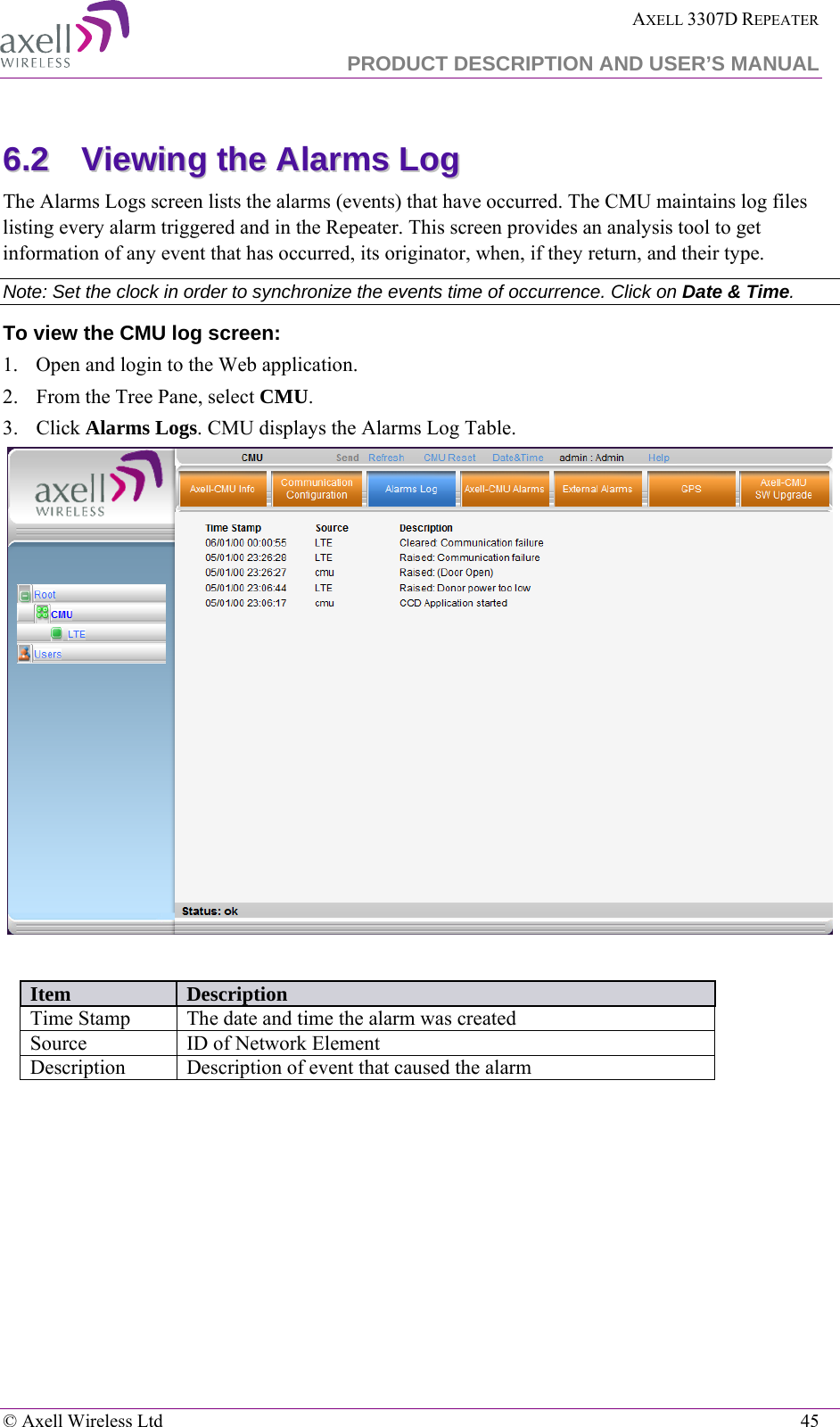
PBE Europe as Axell Wireless DFR-LTE-3307 D-SBR-3307 LTE Booster User Manual High Selectivity Digital 1800MHz Repeater
Axell Wireless D-SBR-3307 LTE Booster High Selectivity Digital 1800MHz Repeater
UserManual.wiki
>
PBE Europe as Axell Wireless
>
DFR LTE 3307 User Manual
User Manual
Navigation menu
Upload a User Manual
Namespaces
Wiki Guide
HTML
PDF
Info
Views
User Manual
Discussion / Help
Navigation
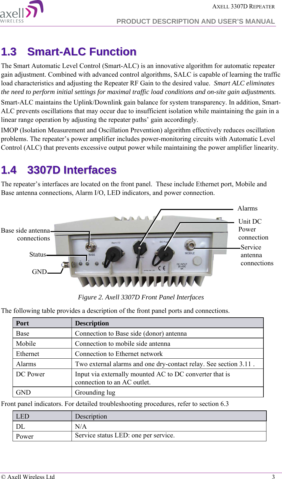
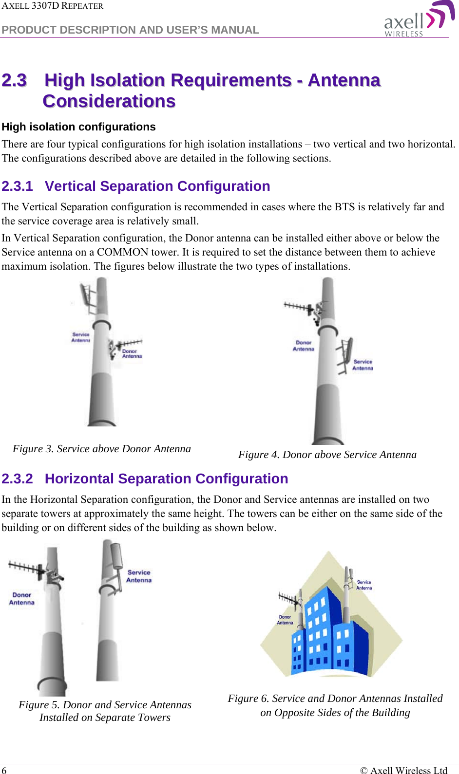
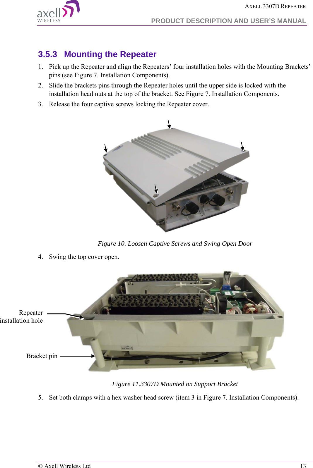
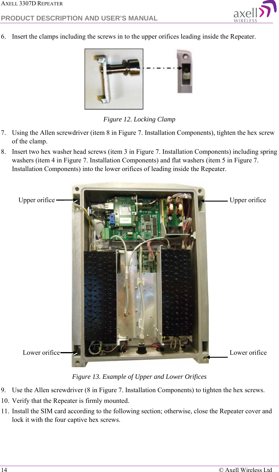
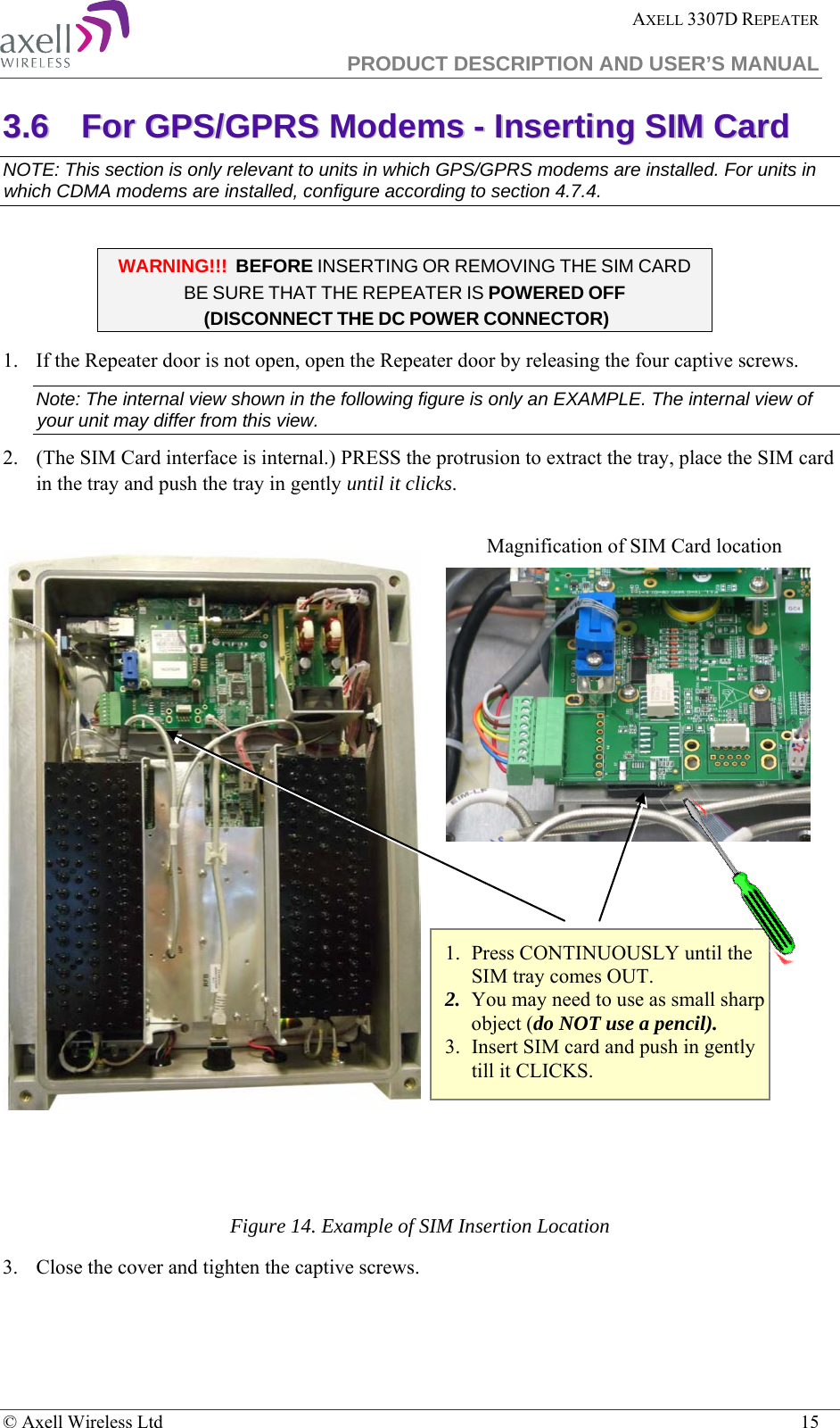
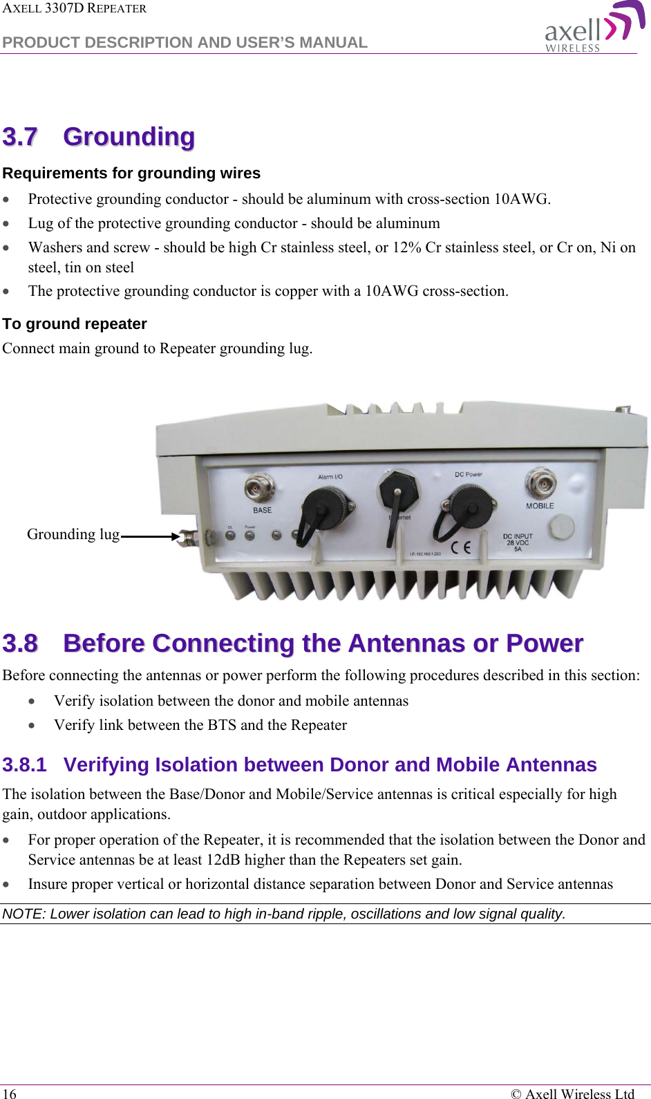
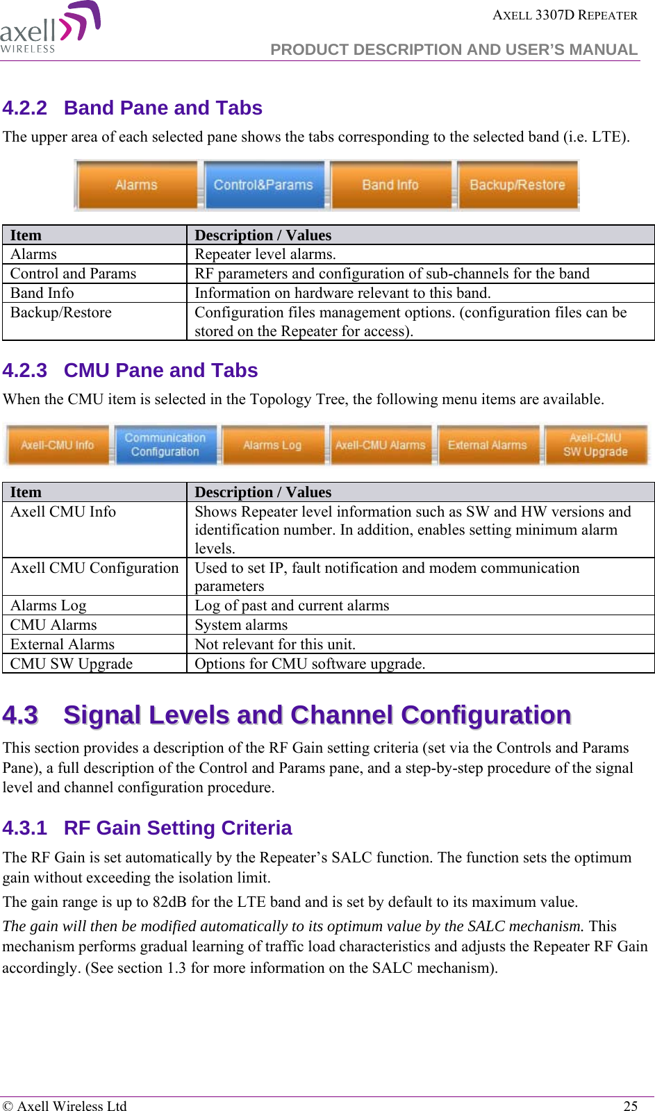
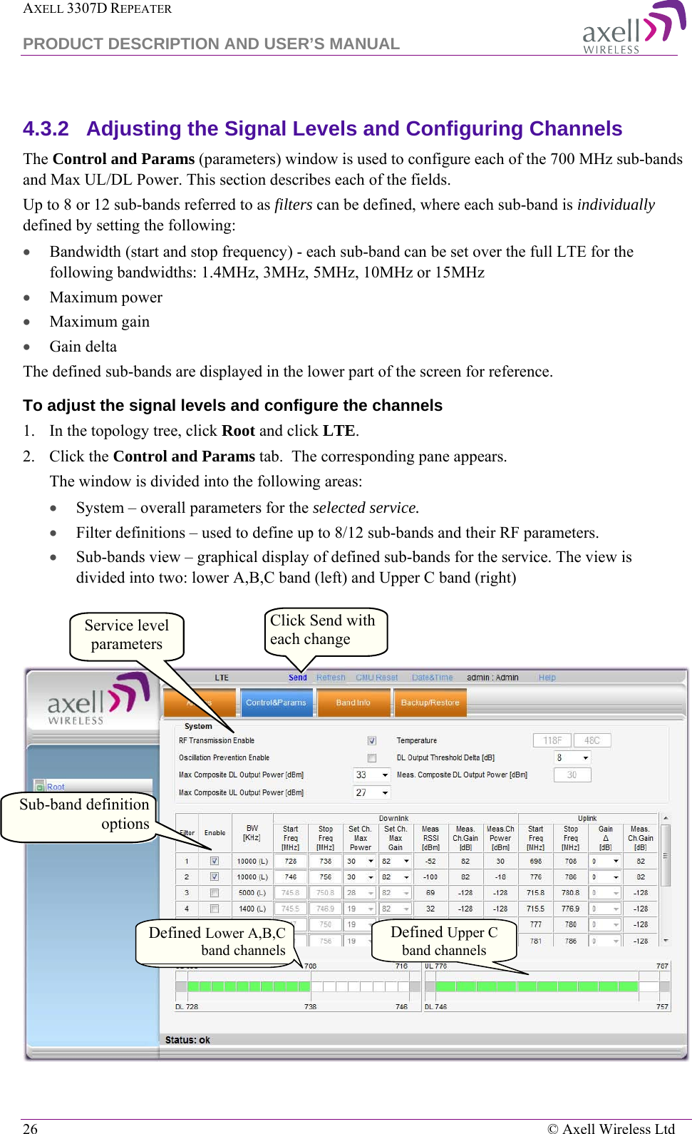
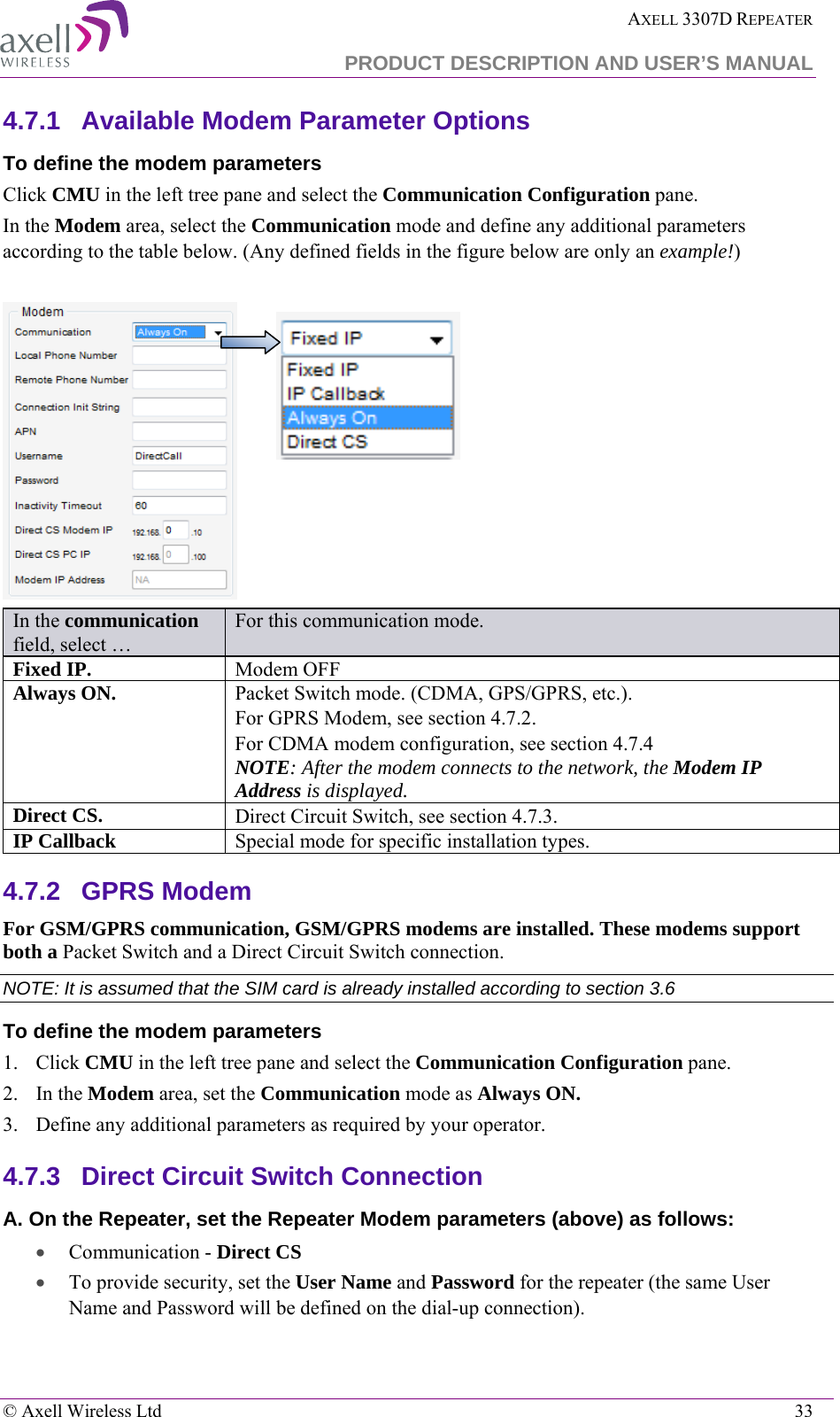
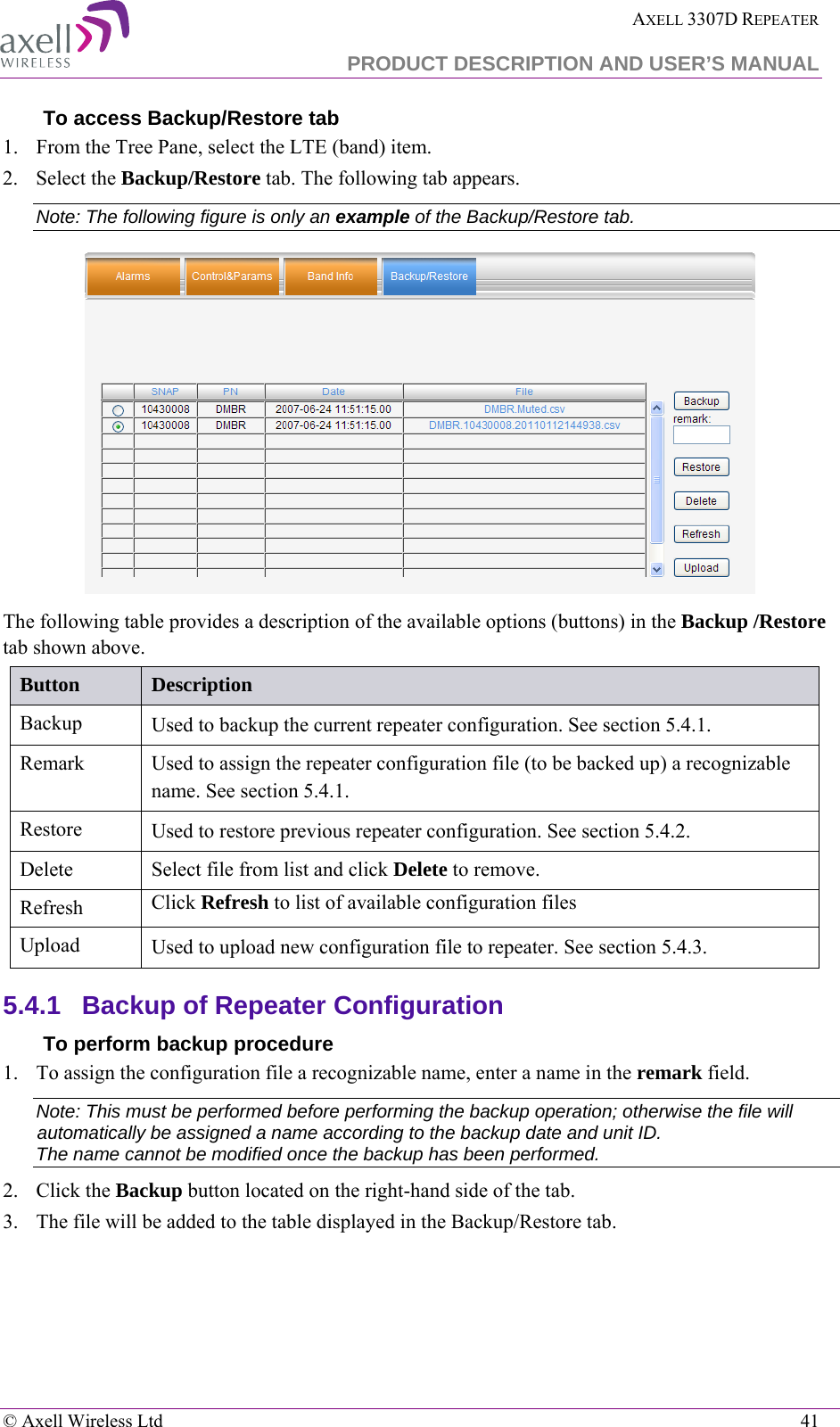
![AXELL 3307D REPEATER PRODUCT DESCRIPTION AND USER’S MANUAL 8 © Axell Wireless Ltd 3.1.4 RF Cable Installation Guidelines Required: • For all coaxial connections to/from the Repeater - high performance, flexible, low loss 50Ω coaxial communications cable. • All cables shall be weather-resistant type. • Cable length - determined by the Repeater installation plan. When calculating the cable length, take into account excess cable slack so as not to limit the insertion paths. 3.1.5 Power Requirements 3.1.5.1 Overcurrent Protection A readily accessible, listed branch circuit over current protective device, rated 20 A, must be incorporated in the building wiring. 3.1.5.2 North American Power Wiring Select a power supply cord that is UL Listed and CSA Certified: 3 - conductor, 18 AWG, terminated in a molded on plug cap rated 125 V, 15 A, with a minimum length of 1.5m [six feet] but no longer than 4.5m. 3.1.6 Grounding Wires Requirements Requirements for grounding wires • Protective grounding conductor - should be aluminum with cross-section 10AWG. • Lug of the protective grounding conductor - should be aluminum • Washers and screw - should be high Cr stainless steel, or 12% Cr stainless steel, or Cr on, Ni on steel, tin on steel 33..22 OOvveerrvviieeww ooff tthhee IInnssttaallllaattiioonn PPrroocceedduurree NOTE: The Donor and Mobile antennas can be positioned and installed (without connection to the Repeater) at any time either before or after mounting and grounding the Repeater. 1. Unpack the Repeater kit. 2. Mount the Repeater on the wall. 3. For GPS/GPRS modems - open the Repeater and insert the SIM card. 4. Ground the Repeater. 5. If you have not already done so, position and install the Base and Mobile antennas in the relevant locations. 6. Before powering up the Repeater: • Verify isolation between the donor and mobile antennas • Verify link between the BTS and Base Repeater. 7. Connect the antennas to the Repeater. 8. Power-up the Repeater. 9. Optional - connect the external alarms. This can be done at any time, before or after powering up the Repeater.](https://usermanual.wiki/PBE-Europe-as-Axell-Wireless/DFR-LTE-3307/User-Guide-1494427-Page-14.png)