PBE Europe as Axell Wireless DFR-LTE-3307 D-SBR-3307 LTE Booster User Manual High Selectivity Digital 1800MHz Repeater
Axell Wireless D-SBR-3307 LTE Booster High Selectivity Digital 1800MHz Repeater
User Manual
AXELL 3307D REPEATER
PRODUCT DESCRIPTION AND USER’S MANUAL
High Selectivity Digital 700MHz Repeater
Product Description and User’s Manual
for Axell 3307D Repeater
THIS DOCUMENT IS VALID FOR THE FOLLOWING REPEATER MODELS:
D-SBR 3307
D-SBR 3307-12
AXELL 3307D REPEATER
PRODUCT DESCRIPTION AND USER’S MANUAL
II © Axell Wireless Ltd
Copyright © 2011 Axell Wireless Ltd
All rights reserved.
No part of this document may be copied, distributed, transmitted, transcribed, stored in a retrieval system, or
translated into any human or computer language without the prior written permission of Axell Wireless Ltd.
The manufacturer has made every effort to ensure that the instructions contained in this document are
adequate and free of errors and omissions. The manufacturer will, if necessary, explain issues which may not
be covered by this document. The manufacturer's liability for any errors in the document is limited to the
correction of errors and the aforementioned advisory services.
This document has been prepared to be used by professional and properly trained personnel, and the
customer assumes full responsibility when using them. The manufacturer welcomes customer comments as
part of the process of continual development and improvement of the documentation in the best way possible
from the user's viewpoint. Please submit your comments to the nearest Axell Wireless sales representative.
Contact Information
Headquarters Axell Wireless
Aerial House
Asheridge Road
Chesham
Buckinghamshire HP5 2QD
United Kingdom
Tel: +44 1494 777000
Fax: +44 1494 777002
Commercial inquiries
info@axellwireless.com
Web site
www.axellwireless.com
Support issues
support@axellwireless.com
Technical Support Line, English speaking
+44 1494 777 777
Contact information for Axell Wireless offices in other countries can be found on our web site,
www.axellwireless.com

AXELL 3307D REPEATER
PRODUCT DESCRIPTION AND USER’S MANUAL
© Axell Wireless Ltd III
About This Manual
This Product Manual provides the following information:
• Description of the Repeater
• Procedures for setup, configuration and checking the proper operation of the Repeater
• Maintenance and troubleshooting procedures
For whom it is Intended
This Product Manual is intended for experienced technicians and engineers. It is assumed that the
customers installing, operating, and maintaining Axell Wireless Repeaters are familiar with the basic
functionality of Repeaters.
Notice
Confidential - Authorized Customer Use
This document may be used in its complete form only and is solely for the use of Axell Wireless
employees and authorized Axell Wireless channels or customers. The material herein is proprietary to
Axell Wireless. Any unauthorized reproduction, use or disclosure of any part thereof is strictly
prohibited.
All trademarks and registered trademarks are the property of their respective owners.
Disclaimer of Liability
Contents herein are current as of the date of publication. Axell Wireless reserves the right to change
the contents without prior notice. The information furnished by Axell Wireless in this document is
believed to be accurate and reliable. However, Axell Wireless assumes no responsibility for its use.
In no event shall Axell Wireless be liable for any damage resulting from loss of data, loss of use, or
loss of profits and Axell Wireless further disclaims any and all liability for indirect, incidental,
special, consequential or other similes damages. This disclaimer of liability applies to all products,
publications and services during and after the warranty period.
Safety Instructions and Warnings
Throughout this manual, important safety warnings and admonishments are included to warn of
possible hazards to persons or equipment. A safety warning identifies a possible hazard and then
describes what may happen if the hazard is not avoided. The safety warnings – in the form of
Dangers, Warnings and Cautions must be followed at all times. These warnings are flagged by the
use of a warning icon, usually the triangular alert icon seen below. The exclamation point within the
triangular alert icon is intended to warn the operator or service personnel of operation and
maintenance from factors relating to the product and its operating environment, which could pose a
safety hazard.

AXELL 3307D REPEATER
PRODUCT DESCRIPTION AND USER’S MANUAL
IV © Axell Wireless Ltd
General Safety Warnings Concerning Use of This System
Always observe standard safety precautions during installation, operation and maintenance of this
product. Only a qualified and authorized personnel should carry out adjustment, maintenance or
repairs to the components of this equipment.
Danger: Electrical Shock
To prevent electrical shock when installing or modifying the system power wiring, disconnect the
wiring at the power source before working with un insulated wires or terminals.
Caution: RF Exposure
Installation of an antenna must comply with the FCC RF exposure requirements.
Exclusive Remedies
The remedies provided herein are the Buyer’s sole and exclusive remedies. Axell Wireless shall not
be viable for any direct, incidental, or consequential damages, whether based on contract, tort, or any
legal theory.

AXELL 3307D REPEATER
PRODUCT DESCRIPTION AND USER’S MANUAL
© Axell Wireless Ltd V
Table of Contents
1 Introduction ................................................................................................................... 1
1.1 Features ................................................................................................................................ 2
1.2 Modem Support .................................................................................................................... 2
1.3 Smart-ALC Function ............................................................................................................ 3
1.4 3307D Interfaces ................................................................................................................... 3
2 Antenna Requirements ................................................................................................. 4
2.1 Base (Donor) Antenna ......................................................................................................... 4
2.1.1 Required Antenna Information .................................................................................. 4
2.1.2 Donor Antenna specifications .................................................................................... 4
2.1.3 Installation Criteria ..................................................................................................... 4
2.2 Mobile (Service) Antenna .................................................................................................... 5
2.2.1 Required Antenna Information .................................................................................. 5
2.2.2 Recommended Antennas .......................................................................................... 5
2.2.3 Mobile (Service) Antenna Installation Criteria ........................................................... 5
2.3 High Isolation Requirements - Antenna Considerations ................................................. 6
2.3.1 Vertical Separation Configuration.............................................................................. 6
2.3.2 Horizontal Separation Configuration ......................................................................... 6
3 Installing the Repeater .................................................................................................. 7
3.1 Repeater Pre-Installation Requirements ............................................................................ 7
3.1.1 Safety Guidelines ...................................................................................................... 7
3.1.2 Required BTS Information ......................................................................................... 7
3.1.3 Criteria for Repeater Installation Location ................................................................. 7
3.1.4 RF Cable Installation Guidelines ............................................................................... 8
3.1.5 Power Requirements ................................................................................................. 8
3.1.6 Grounding Wires Requirements ................................................................................ 8
3.2 Overview of the Installation Procedure ............................................................................. 8
3.3 Required Tools and Materials ............................................................................................. 9
3.4 Unpacking ............................................................................................................................. 9
3.5 Mounting the 3307D ........................................................................................................... 11
3.5.1 Pre-Mounting Procedure ......................................................................................... 11
3.5.2 Installing the Mounting Bracket ............................................................................... 12
3.5.3 Mounting the Repeater ............................................................................................ 13
3.6 For GPS/GPRS Modems - Inserting SIM Card ................................................................. 15
3.7 Grounding ........................................................................................................................... 16
3.8 Before Connecting the Antennas or Power ..................................................................... 16
3.8.1 Verifying Isolation between Donor and Mobile Antennas ....................................... 16
3.8.2 Verify Link between BTS and Repeater .................................................................. 17
3.9 Antenna Connections ........................................................................................................ 18
3.10 Power-on ............................................................................................................................. 18
3.11 External Alarms and Relay Connections ......................................................................... 18
3.11.1 Load Restrictions ..................................................................................................... 19
4 Initial Setup and Commissioning .............................................................................. 20
4.1 Open a Local WEB Session to the Repeater ................................................................... 20
4.1.1 Connecting to the Repeater .................................................................................... 20
4.1.2 Configure the Computer Network Parameters ........................................................ 21

AXELL 3307D REPEATER
PRODUCT DESCRIPTION AND USER’S MANUAL
VI © Axell Wireless Ltd
4.1.3 Login to the Repeater .............................................................................................. 23
4.2 Navigating the Web GUI Application ................................................................................ 24
4.2.1 Operation Buttons.................................................................................................... 24
4.2.2 Band Pane and Tabs ............................................................................................... 25
4.2.3 CMU Pane and Tabs ............................................................................................... 25
4.3 Signal Levels and Channel Configuration ....................................................................... 25
4.3.1 RF Gain Setting Criteria .......................................................................................... 25
4.3.2 Adjusting the Signal Levels and Configuring Channels .......................................... 26
4.4 Setting Date and Time ....................................................................................................... 29
4.5 Configuring the External Alarms ...................................................................................... 29
4.6 Communication and System Parameters ........................................................................ 30
4.6.1 The Communication Configuration Tab .................................................................. 30
4.6.2 IP Address Configuration ........................................................................................ 30
4.6.3 Configuring Notification Method - SNMP Trap or SMS ........................................... 31
4.6.4 AEM (Axell Element Manager) Configuration ......................................................... 32
4.7 Modem Communication Setup ......................................................................................... 32
4.7.1 Available Modem Parameter Options...................................................................... 33
4.7.2 GPRS Modem ......................................................................................................... 33
4.7.3 Direct Circuit Switch Connection ............................................................................. 33
4.7.4 CDMA Modem ......................................................................................................... 35
5 Administrative Operations ......................................................................................... 37
5.1 User Management .............................................................................................................. 37
5.1.1 User Levels .............................................................................................................. 37
5.1.2 Viewing the List of Defined Users ........................................................................... 37
5.1.3 Adding Users ........................................................................................................... 38
5.1.4 Editing a User .......................................................................................................... 38
5.1.5 Deleting a User ........................................................................................................ 39
5.2 Viewing Band Information ................................................................................................. 39
5.3 Repeater Software Upgrade .............................................................................................. 40
5.4 Backup/Restore of Repeater Configuration .................................................................... 40
5.4.1 Backup of Repeater Configuration .......................................................................... 41
5.4.2 Restoring Previous Repeater Configuration ............................................................ 42
5.4.3 Uploading New Configuration File to Repeater ....................................................... 42
5.4.4 Saving Configuration File to Computer ................................................................... 42
6 Monitoring and Troubleshooting ............................................................................... 43
6.1 Repeater Alarms and Troubleshooting ............................................................................ 43
6.2 Viewing the Alarms Log .................................................................................................... 45
6.3 3307D LED Troubleshooting ............................................................................................. 46
Appendix: 3307D Specifications .............................................................................................. 47
AXELL 3307D REPEATER
PRODUCT DESCRIPTION AND USER’S MANUAL
© Axell Wireless Ltd 1
1
1
I
In
nt
tr
ro
od
du
uc
ct
ti
io
on
n
Axell 3307D is a 700 MHz band LTE technology selective indoor mid-repeater that simultaneously
supports the LTE lower and upper frequency range: Lower700MHz A,B,C and Upper 700MHz C.
The Repeater supports advanced digital filtering capabilities. Up to 8 or 12 (model dependent) LTE
non-contiguous sub-bands can be selected via simple intuitive GUI, where each sub-band is
independently tunable across the entire LTE band. The gain and output power can be set individually
in each of these sub-bands. This provides an optimal solution for operators that have non-contiguous
spectrum.
The repeater provides highly accurate out-of-band-rejection and simple, GUI based procedures for
adjusting the pass band according to the 700 MHz spectrum.
3307D includes the SmartALC power control algorithm that automatically optimizes the gain setting
by learning the actual range of RSSI levels over a user-specified period of time. The SmartALC
algorithm prevents oscillations, reduces the amount of isolation required by the system and optimizes
the system to minimize noise rise at the donor cell site.
GUI based web management is supported through both Ethernet and remote wireless connections
(wireless connection provided by an integrated modem). Local setup can be performed through a
connection to the Ethernet port using a cross-cable.
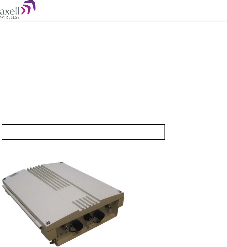
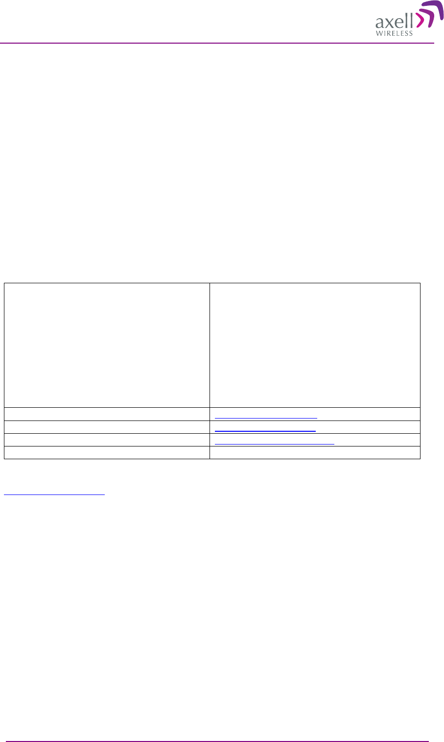
Figure 1. Axell 3307D Repeater

AXELL 3307D REPEATER
PRODUCT DESCRIPTION AND USER’S MANUAL
2 © Axell Wireless Ltd
1
1.
.1
1
F
Fe
ea
at
tu
ur
re
es
s
• Indoor Repeater supporting simultaneously the LTE band: Lower A,B,C and Upper C 700MHz
• Up to 8 or 12 (model dependent) software selectable non-contiguous sub-bands in any
combination
• Each sub-band can be set over the full LTE band for the following bandwidths: 1.4MHz, 3MHz,
5MHz, 10MHz or 15MHz or 20MHz to meet the LTE 36.106 standard
• Individual gain and power settings for each sub-band
• Composite downlink Output Power: + 33 dBm;
• Composite uplink Output Power: + 27 dBm
• RF Gain: 82 dB
• High linear amplification, high spectral purity and excellent out-of-band interference prevention
• SmartALC™ technology:
• Automatically sets optimum gain
• Prevents oscillations and balances coverage
• Ensures transparent network operation
• Highly accurate frequency selection
• Configuration backup and restore via simple, intuitive GUI options
• Wallmount
• Simple setup via an intuitive GUI application
• Supports SMS and SNMP fault notification
• Remote Web access monitoring and control via either an integrated Wireless CDMA or
GSM/GPRS modem (supporting Packet Switch)
• Simultaneous support for both static and dynamic address allocation (two independent IPs)
1
1.
.2
2
M
Mo
od
de
em
m
S
Su
up
pp
po
or
rt
t
The Repeater supports two types of integrated modems that required different setup procedures:
• GSM/GPRS – insert SIM card according to section 3.6 and setup up modem according to section
4.7.2.
• CDMA – modem is continuously ON. Setup according to section 4.7.4
AXELL 3307D REPEATER
PRODUCT DESCRIPTION AND USER’S MANUAL
© Axell Wireless Ltd 3
1
1.
.3
3
S
Sm
ma
ar
rt
t-
-A
AL
LC
C
F
Fu
un
nc
ct
ti
io
on
n
The Smart Automatic Level Control (Smart-ALC) is an innovative algorithm for automatic repeater
gain adjustment. Combined with advanced control algorithms, SALC is capable of learning the traffic
load characteristics and adjusting the Repeater RF Gain to the desired value. Smart ALC eliminates
the need to perform initial settings for maximal traffic load conditions and on-site gain adjustments.
Smart-ALC maintains the Uplink/Downlink gain balance for system transparency. In addition, Smart-
ALC prevents oscillations that may occur due to insufficient isolation while maintaining the gain in a
linear range operation by adjusting the repeater paths’ gain accordingly.
IMOP (Isolation Measurement and Oscillation Prevention) algorithm effectively reduces oscillation
problems. The repeater’s power amplifier includes power-monitoring circuits with Automatic Level
Control (ALC) that prevents excessive output power while maintaining the power amplifier linearity.
1
1.
.4
4
3
33
30
07
7D
D
I
In
nt
te
er
rf
fa
ac
ce
es
s
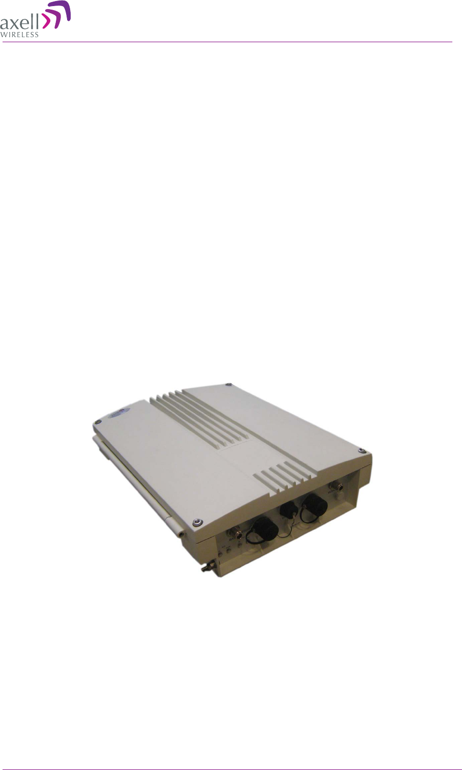
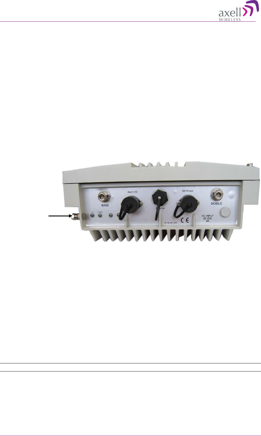
The repeater’s interfaces are located on the front panel. These include Ethernet port, Mobile and
Base antenna connections, Alarm I/O, LED indicators, and power connection.
Figure 2. Axell 3307D Front Panel Interfaces
The following table provides a description of the front panel ports and connections.
Port Description
Base Connection to Base side (donor) antenna
Mobile Connection to mobile side antenna
Ethernet Connection to Ethernet network
Alarms Two external alarms and one dry-contact relay. See section 3.11 .
DC Power Input via externally mounted AC to DC converter that is
connection to an AC outlet.
GND Grounding lug
Front panel indicators. For detailed troubleshooting procedures, refer to section 6.3
LED Description
DL N/A
Power
Service status LED: one per service.
Service
antenna
connections
Unit DC
Power
connection
Base side antenna
connections
Status
Alarms
GND

AXELL 3307D REPEATER
PRODUCT DESCRIPTION AND USER’S MANUAL
4 © Axell Wireless Ltd
2
2
A
An
nt
te
en
nn
na
a
R
Re
eq
qu
ui
ir
re
em
me
en
nt
ts
s
This chapter provides information on the specifications of the donor and service antennas suitable for
operation with this repeater, and on the installation requirements of the antennas.
2
2.
.1
1
B
Ba
as
se
e
(
(D
Do
on
no
or
r)
)
A
An
nt
te
en
nn
na
a
The Base (Donor) antenna is usually installed outdoors and is either a directional antenna such as a
Yagi or a Panel antenna.
2.1.1 Required Antenna Information
You will require the following antenna information
• Antenna type and characteristics
• Height
• Length and type of coaxial cable required for connecting the Donor antenna to the Repeater and
the attenuation.
2.1.2 Donor Antenna specifications
• Yagi type or similar – 12 to 20 dBi gain, very sharp beam pointed to the BTS.
• Cable and jumper loss is at least 2dB.
• Example of antenna's typical specifications:
Gain: 8 dBd (=10.1 dBi)
VSWR: < 1:5:1
Impedance: 50 ohm
2.1.3 Installation Criteria
NOTE: Verify that the antennas meet requirements described in section 2.1.
Installation requirements:
• Select a location for the Donor antenna and verify that there is enough signal strength at that
location.
• Install the Donor Antenna at the designated height.
• The antenna should point to the direction of the base station for maximum input power.
• Verify that the antenna is in the base stations line of sight (raise the antenna if necessary).
• Install the donor antenna at a higher level (i.e. floor) than the mobile antenna.
• Must be installed at a minimum distance of 1 meter from any personnel within the area.

AXELL 3307D REPEATER
PRODUCT DESCRIPTION AND USER’S MANUAL
© Axell Wireless Ltd 5
2
2.
.2
2
M
Mo
ob
bi
il
le
e
(
(S
Se
er
rv
vi
ic
ce
e)
)
A
An
nt
te
en
nn
na
a
The Mobile (Service) antenna is installed indoors, where the type of antenna depends on the
application.
2.2.1 Required Antenna Information
The following antenna requirements, specifications and site considerations should be met.
• Service area type and size
• Antenna type and characteristics
• Height
• Length and type of coaxial cable required for connecting the Donor antenna to the Repeater and
the attenuation.
2.2.2 Recommended Antennas
The following describes the requirements for an omni-directional mobile used for indoor
applications.
Specifications:
• One or a combination of the following antennas can be used: Ceiling Mount Patch antenna, Wall
Mount Patch antenna, Corner Reflector.
• Omni directional antenna with a 0 to 2 dBi typical gain, or wide beam with up to 10 dBi gain.
• Example of omni-directional antenna specifications:
Gain: 0 to 2 dBi
VSWR: < 2:1
Impedance: 50 ohm
• Choose an antenna with high side lobe attenuation which enables maximum isolation from the
service/ mobile antenna.
2.2.3 Mobile (Service) Antenna Installation Criteria
Determine the antenna installation configuration, according to the transmission requirements and the
installation site conditions.
Installation requirements:
• An indoor antenna should be installed at a convenient location. It should be free of metallic
obstruction.
• Install the Service Antenna at the designated height and tune it roughly toward the Service
coverage area.
• Installation of this antenna must provide a minimum separation distance of 20 cm from any
personnel within the area.
Note: If the power is divided into more than 5 antennas that have a large coverage area than the
separation distance can be less than 20 cm.
• Cable and jumper loss is at least 2dB.
AXELL 3307D REPEATER
PRODUCT DESCRIPTION AND USER’S MANUAL
6 © Axell Wireless Ltd
2
2.
.3
3
H
Hi
ig
gh
h
I
Is
so
ol
la
at
ti
io
on
n
R
Re
eq
qu
ui
ir
re
em
me
en
nt
ts
s
-
-
A
An
nt
te
en
nn
na
a
C
Co
on
ns
si
id
de
er
ra
at
ti
io
on
ns
s
High isolation configurations
There are four typical configurations for high isolation installations – two vertical and two horizontal.
The configurations described above are detailed in the following sections.
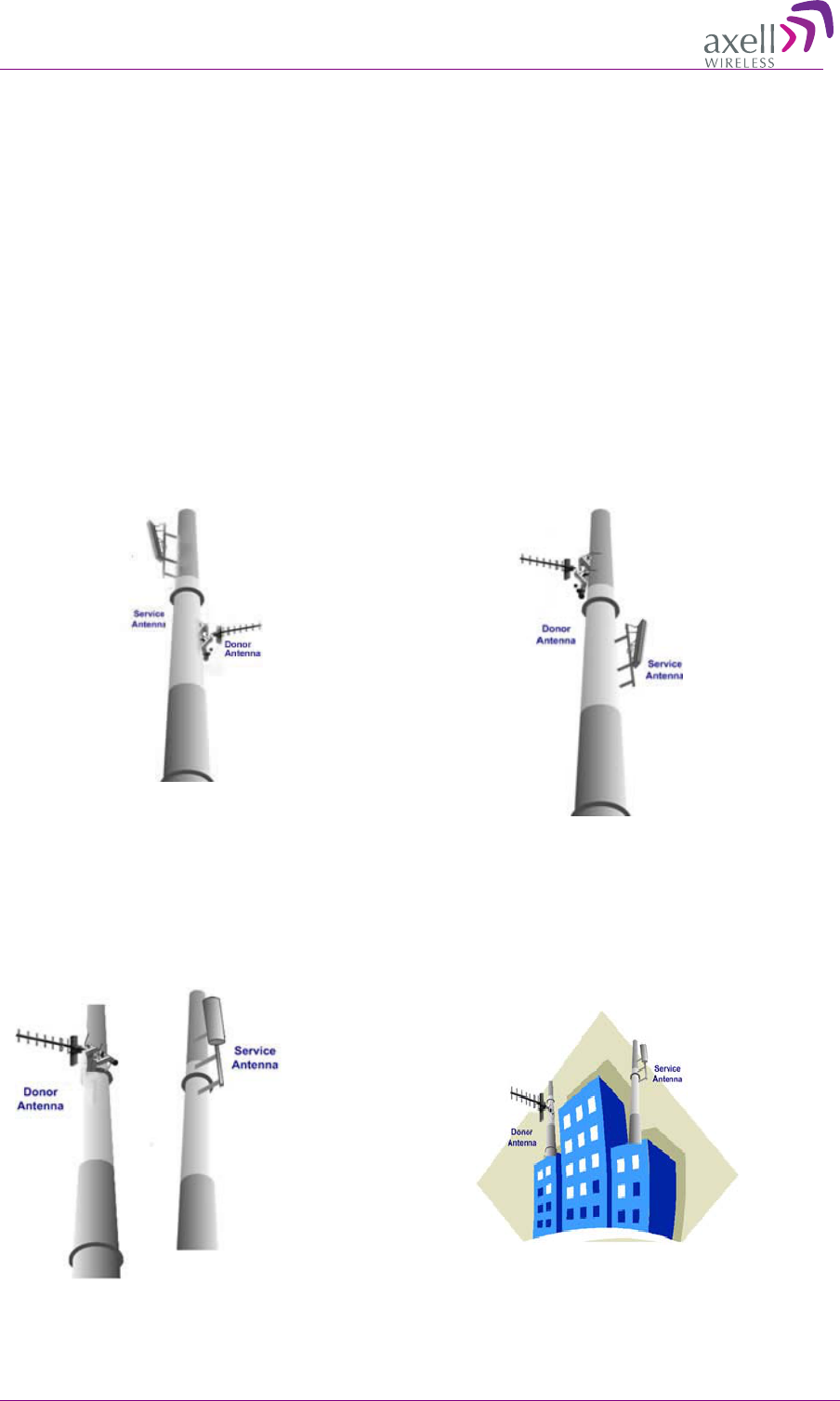
2.3.1 Vertical Separation Configuration
The Vertical Separation configuration is recommended in cases where the BTS is relatively far and
the service coverage area is relatively small.
In Vertical Separation configuration, the Donor antenna can be installed either above or below the
Service antenna on a COMMON tower. It is required to set the distance between them to achieve
maximum isolation. The figures below illustrate the two types of installations.
Figure 3. Service above Donor Antenna
Figure 4. Donor above Service Antenna
2.3.2 Horizontal Separation Configuration
In the Horizontal Separation configuration, the Donor and Service antennas are installed on two
separate towers at approximately the same height. The towers can be either on the same side of the
building or on different sides of the building as shown below.
Figure 5. Donor and Service Antennas
Installed on Separate Towers
Figure 6. Service and Donor Antennas Installed
on Opposite Sides of the Building

AXELL 3307D REPEATER
PRODUCT DESCRIPTION AND USER’S MANUAL
© Axell Wireless Ltd 7
3
3
I
In
ns
st
ta
al
ll
li
in
ng
g
t
th
he
e
R
Re
ep
pe
ea
at
te
er
r
3
3.
.1
1
R
Re
ep
pe
ea
at
te
er
r
P
Pr
re
e-
-I
In
ns
st
ta
al
ll
la
at
ti
io
on
n
R
Re
eq
qu
ui
ir
re
em
me
en
nt
ts
s
3.1.1 Safety Guidelines
Before installing the Repeater, review the following safety information:
• Follow all local safety regulations when installing the Repeater.
• Only qualified personnel are authorized to install and maintain the Repeater.
• Ground the Repeater with the grounding bolt located on the external lower side of the Repeater).
• Do not use the grounding bolt to connect external devices.
• Follow Electro-Static Discharge (ESD) precautions.
• Use low loss cables to connect the antennas to the Repeater.
3.1.2 Required BTS Information
Required BTS Information
• BTS channels
• BTS output power per channel
• BTS antenna gain
• BTS antenna height
• Distance from Repeater site to BTS
3.1.3 Criteria for Repeater Installation Location
The following criteria should be considered when selecting the Repeater installation site location:
• Application type
• General surroundings
• Available installation
• Install the Repeater in a shielded, ventilated, and easy-to-reach area.
• Verify that there is a minimum of a 50 cm (20”) radius of space around the Repeater, enabling
easy access to the repeater for maintenance and on-site inspection.
• Distance from antenna site - It is recommended that the installation location be as close as
possible to the antenna site in order to maintain the cable loss to a minimum.
• The Repeater is convection cooled so airflow and alternation should be possible.
• Follow Electro-Static Discharge (ESD) precautions.
• Install the Repeater close to the service area to monitor the output power.
• Use low loss cables to connect the antennas to the Repeater.

AXELL 3307D REPEATER
PRODUCT DESCRIPTION AND USER’S MANUAL
8 © Axell Wireless Ltd
3.1.4 RF Cable Installation Guidelines
Required:
• For all coaxial connections to/from the Repeater - high performance, flexible, low loss 50Ω
coaxial communications cable.
• All cables shall be weather-resistant type.
• Cable length - determined by the Repeater installation plan. When calculating the cable length,
take into account excess cable slack so as not to limit the insertion paths.
3.1.5 Power Requirements
3.1.5.1 Overcurrent Protection
A readily accessible, listed branch circuit over current protective device, rated 20 A, must be
incorporated in the building wiring.
3.1.5.2 North American Power Wiring
Select a power supply cord that is UL Listed and CSA Certified: 3 - conductor, 18 AWG, terminated
in a molded on plug cap rated 125 V, 15 A, with a minimum length of 1.5m [six feet] but no longer
than 4.5m.
3.1.6 Grounding Wires Requirements
Requirements for grounding wires
• Protective grounding conductor - should be aluminum with cross-section 10AWG.
• Lug of the protective grounding conductor - should be aluminum
• Washers and screw - should be high Cr stainless steel, or 12% Cr stainless steel, or Cr on, Ni on
steel, tin on steel
3
3.
.2
2
O
Ov
ve
er
rv
vi
ie
ew
w
o
of
f
t
th
he
e
I
In
ns
st
ta
al
ll
la
at
ti
io
on
n
P
Pr
ro
oc
ce
ed
du
ur
re
e
NOTE: The Donor and Mobile antennas can be positioned and installed (without connection to the
Repeater) at any time either before or after mounting and grounding the Repeater.
1. Unpack the Repeater kit.
2. Mount the Repeater on the wall.
3. For GPS/GPRS modems - open the Repeater and insert the SIM card.
4. Ground the Repeater.
5. If you have not already done so, position and install the Base and Mobile antennas in the relevant
locations.
6. Before powering up the Repeater:
• Verify isolation between the donor and mobile antennas
• Verify link between the BTS and Base Repeater.
7. Connect the antennas to the Repeater.
8. Power-up the Repeater.
9. Optional - connect the external alarms. This can be done at any time, before or after powering up
the Repeater.
AXELL 3307D REPEATER
PRODUCT DESCRIPTION AND USER’S MANUAL
© Axell Wireless Ltd 9
3
3.
.3
3
R
Re
eq
qu
ui
ir
re
ed
d
T
To
oo
ol
ls
s
a
an
nd
d
M
Ma
at
te
er
ri
ia
al
ls
s
The following tools are required for the 3307D installation procedure:
• Standard professional tool box (not supplied)
• Adjustable wrench (not supplied)
• Power Drill Driver (not supplied) - supporting 12 mm concrete drills
• Allen screwdriver (supplied)
3
3.
.4
4
U
Un
np
pa
ac
ck
ki
in
ng
g
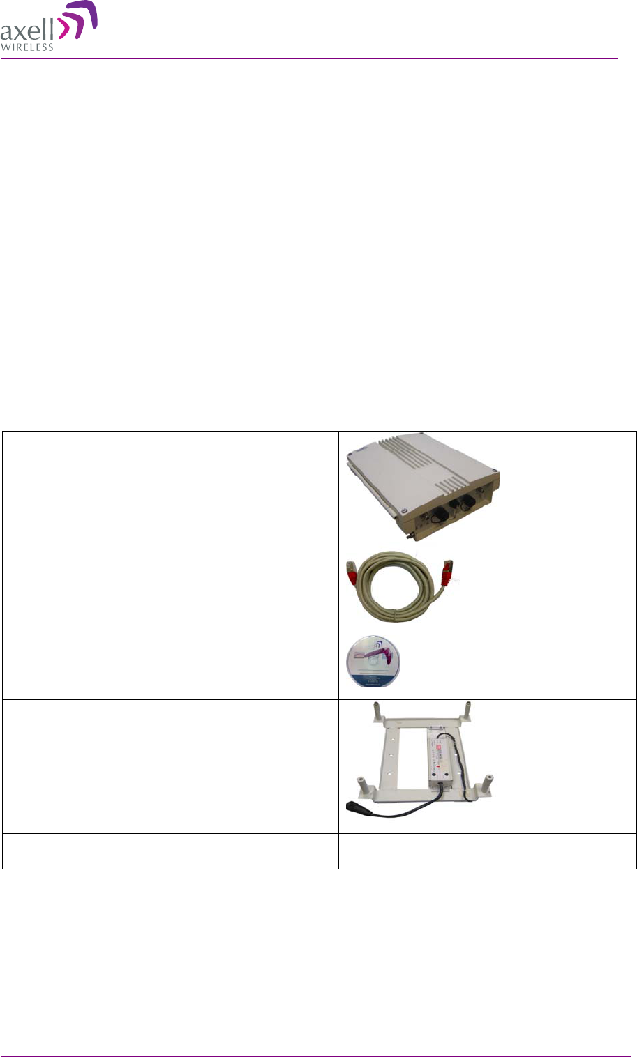
Upon receiving the 3307D unit, perform the following:
• Examine the shipping container for damage before unpacking the unit.
• Perform a visual inspection to reveal any physical damage to the equipment.
• Verify that all of the equipment (listed below) is included (see also the following page).
Otherwise contact Axell Wireless.
3307D single-band Repeater
Ethernet RJ-45 LAN cable
CD with documentations
Mounting Bracket with AC to DC power converter.
RS-232 to CDMA modem interface Cable
Only supplied with unit including CDMA
modem

AXELL 3307D REPEATER
PRODUCT DESCRIPTION AND USER’S MANUAL
10 © Axell Wireless Ltd
Additional (supplied) installation
components:
No.
Description
Qty.
1
Flange nut, 5/16
4
2
Wedge anchor,
∅
12 x 65 mm
4
3
Hex washer head
screw,
∅
8 mm
4
4
Washer, spring,
∅
8 mm
4
5 Washer, flat,
∅ 8 mm
2
6
Clamp
2
7
Washer, flat,
∅
28 mm
4
8
Screwdriver, Allen
1
Figure 7. Installation Components
AXELL 3307D REPEATER
PRODUCT DESCRIPTION AND USER’S MANUAL
© Axell Wireless Ltd 11
3
3.
.5
5
M
Mo
ou
un
nt
ti
in
ng
g
t
th
he
e
3
33
30
07
7D
D
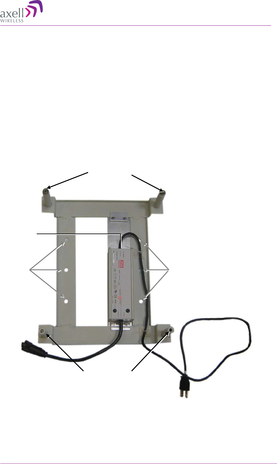
3.5.1 Pre-Mounting Procedure
1. Choose the location of the Repeater on the wall according to the following criteria:
• The location should be at normal eye level height, above ground.
• Be sure to allow easy access to the Repeater for maintenance and on-site inspection.
2. Place the Mounting Bracket against the wall and mark the four holes to be drilled at the extreme
four corners of the bracket (additional optional installation holes are also provided).
3. Drill four holes 12mm in diameter and 65mm in depth.
The following illustration shows the bracket with the bracket pins.
Figure 8. 3307D Mounting Holes and Pins
Optional
installation holes
Optional
installation holes
2x bottom holes
2x top holes
Assembled PS
AXELL 3307D REPEATER
PRODUCT DESCRIPTION AND USER’S MANUAL
12 © Axell Wireless Ltd
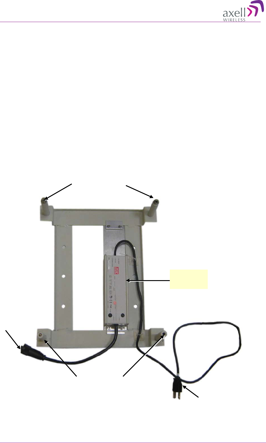
3.5.2 Installing the Mounting Bracket
To install the mounting bracket
1. Insert the four wedge anchors (see item no. 2 in Figure 7. Installation Components) into the
drilled holes and secure them with an adjustable wrench.
2. Remove the hex nut, spring washer and flat washer from each wedge anchor, revealing a screw
from each anchor.
3. Insert a flat washer 28mm in diameter in each of the anchors (see item 7 in Figure 7. Installation
Components).
4. Fit the support bracket on to the anchors (see installation direction in Figure 7. Installation
Components) and secure with the flat washers, spring washers and hex nuts removed in step 2.
5. Verify that the bracket is firmly mounted.
6. Connect the power cable to the power supply and route it to the bottom of the bracket, connect it
to the repeater power input.
7. Connect the AC power cable to the AC power input when instructed to do so.
Figure 9. 3307D Mounting Holes and Pins
2x bottom holes
2x top holes
AC cable
To Repeater
IP65 Weather
resistant PS
AXELL 3307D REPEATER
PRODUCT DESCRIPTION AND USER’S MANUAL
© Axell Wireless Ltd 13
3.5.3 Mounting the Repeater
1. Pick up the Repeater and align the Repeaters’ four installation holes with the Mounting Brackets’
pins (see Figure 7. Installation Components).
2. Slide the brackets pins through the Repeater holes until the upper side is locked with the
installation head nuts at the top of the bracket. See Figure 7. Installation Components.
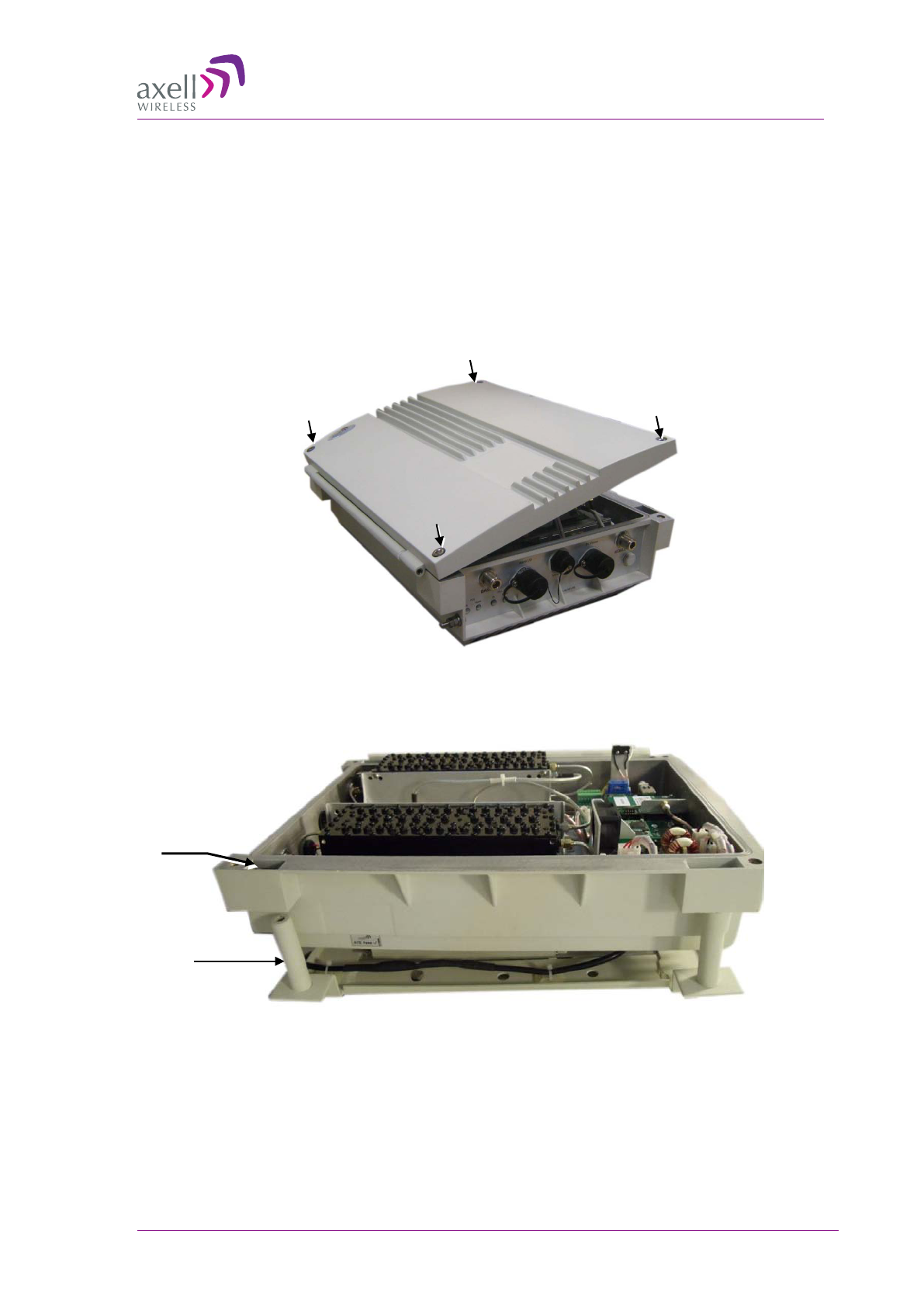
3. Release the four captive screws locking the Repeater cover.
Figure 10. Loosen Captive Screws and Swing Open Door
4. Swing the top cover open.
Figure 11.3307D Mounted on Support Bracket
5. Set both clamps with a hex washer head screw (item 3 in Figure 7. Installation Components).
Bracket pin
Repeater
installation hole
AXELL 3307D REPEATER
PRODUCT DESCRIPTION AND USER’S MANUAL
14 © Axell Wireless Ltd
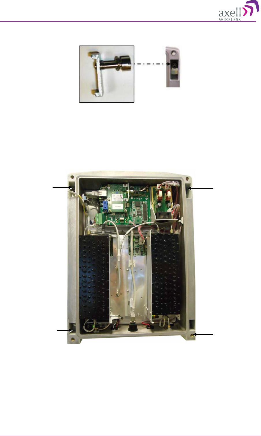
6. Insert the clamps including the screws in to the upper orifices leading inside the Repeater.
Figure 12. Locking Clamp
7. Using the Allen screwdriver (item 8 in Figure 7. Installation Components), tighten the hex screw
of the clamp.
8. Insert two hex washer head screws (item 3 in Figure 7. Installation Components) including spring
washers (item 4 in Figure 7. Installation Components) and flat washers (item 5 in Figure 7.
Installation Components) into the lower orifices of leading inside the Repeater.
Figure 13. Example of Upper and Lower Orifices
9. Use the Allen screwdriver (8 in Figure 7. Installation Components) to tighten the hex screws.
10. Verify that the Repeater is firmly mounted.
11. Install the SIM card according to the following section; otherwise, close the Repeater cover and
lock it with the four captive hex screws.
Upper orifice Upper orifice
Lower orifice
Lower orifice
AXELL 3307D REPEATER
PRODUCT DESCRIPTION AND USER’S MANUAL
© Axell Wireless Ltd 15
3
3.
.6
6
F
Fo
or
r
G
GP
PS
S/
/G
GP
PR
RS
S
M
Mo
od
de
em
ms
s
-
-
I
In
ns
se
er
rt
ti
in
ng
g
S
SI
IM
M
C
Ca
ar
rd
d
NOTE: This section is only relevant to units in which GPS/GPRS modems are installed. For units in
which CDMA modems are installed, configure according to section 4.7.4.
WARNING!!! BEFORE INSERTING OR REMOVING THE SIM CARD
BE SURE THAT THE REPEATER IS POWERED OFF
(DISCONNECT THE DC POWER CONNECTOR)
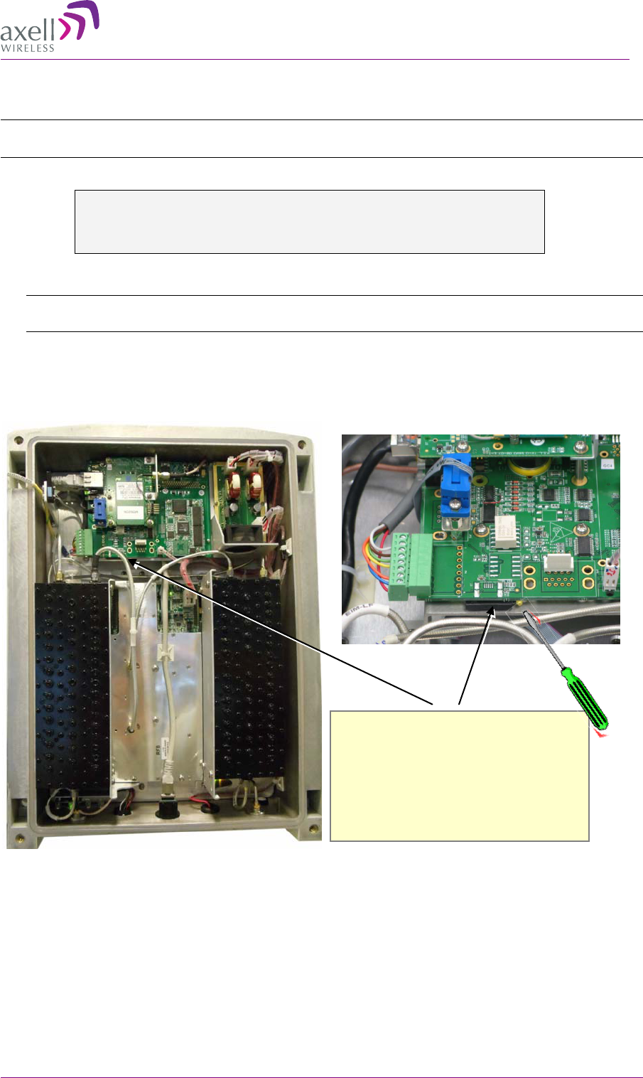
1. If the Repeater door is not open, open the Repeater door by releasing the four captive screws.
Note: The internal view shown in the following figure is only an EXAMPLE. The internal view of
your unit may differ from this view.
2. (The SIM Card interface is internal.) PRESS the protrusion to extract the tray, place the SIM card
in the tray and push the tray in gently until it clicks.
Figure 14. Example of SIM Insertion Location
3. Close the cover and tighten the captive screws.
Magnification of SIM Card location
1. Press CONTINUOUSLY until the
SIM tray comes OUT.
2. You may need to use as small sharp
object (do NOT use a pencil).
3. Insert SIM card and push in gently
till it CLICKS.
AXELL 3307D REPEATER
PRODUCT DESCRIPTION AND USER’S MANUAL
16 © Axell Wireless Ltd
3
3.
.7
7
G
Gr
ro
ou
un
nd
di
in
ng
g
Requirements for grounding wires
• Protective grounding conductor - should be aluminum with cross-section 10AWG.
• Lug of the protective grounding conductor - should be aluminum
• Washers and screw - should be high Cr stainless steel, or 12% Cr stainless steel, or Cr on, Ni on
steel, tin on steel
• The protective grounding conductor is copper with a 10AWG cross-section.
To ground repeater
Connect main ground to Repeater grounding lug.
3
3.
.8
8
B
Be
ef
fo
or
re
e
C
Co
on
nn
ne
ec
ct
ti
in
ng
g
t
th
he
e
A
An
nt
te
en
nn
na
as
s
o
or
r
P
Po
ow
we
er
r
Before connecting the antennas or power perform the following procedures described in this section:
• Verify isolation between the donor and mobile antennas
• Verify link between the BTS and the Repeater
3.8.1 Verifying Isolation between Donor and Mobile Antennas
The isolation between the Base/Donor and Mobile/Service antennas is critical especially for high
gain, outdoor applications.
• For proper operation of the Repeater, it is recommended that the isolation between the Donor and
Service antennas be at least 12dB higher than the Repeaters set gain.
• Insure proper vertical or horizontal distance separation between Donor and Service antennas
NOTE: Lower isolation can lead to high in-band ripple, oscillations and low signal quality.
Grounding lug

AXELL 3307D REPEATER
PRODUCT DESCRIPTION AND USER’S MANUAL
© Axell Wireless Ltd 17
To measure the isolation, proceed as follows:
1. Inject a known signal from a signal generator into one antenna (preferably the Donor antenna).
2. Measure the coupled output from the Service antenna, using the Spectrum analyzer and LNA if
applicable.
3. Perform this procedure across the frequency range of both the Uplink and Downlink bands.
4. Register the lower result for system operation.
3.8.2 Verify Link between BTS and Repeater
WARNING!
PERFORM THIS PROCEDURE BEFORE CONNECTING THE ANTENNAS TO THE
REPEATER OR POWERING ON THE REPEATER. THE REPEATER SHOULD NOT
BE OPERATED PRIOR TO THE VERIFICATION OF THE OPERATING PARAMETER
IN ITS INSTALLATION ENVIRONMENT.
Before connecting the antennas or powering up the Repeater, verifying the Link
between the BTS and the Repeater
This test checks the signal strength from the BTS antenna to the Repeater.
Proceed as follows:
1. Using a Spectrum analyzer, measure the received signal from BTS at the Donor antenna port near
the Repeater.
2. Adjust the Donor antenna direction to receive the maximum signal strength.
3. Compare the received signal strength with the calculated signal strength from the design phase.
In case of discrepancy, check for one of the following:
• Antenna out of direction
• Antenna tuned to side lobe instead of main lobe
• Antenna connector or antenna cable faulty
• Line-of-sight problem (obstruction), etc.
4. Register the signal strength of the downlink channel for the system operation phase.

AXELL 3307D REPEATER
PRODUCT DESCRIPTION AND USER’S MANUAL
18 © Axell Wireless Ltd
3
3.
.9
9
A
An
nt
te
en
nn
na
a
C
Co
on
nn
ne
ec
ct
ti
io
on
ns
s
CAUTION!
DO NOT CONNECT THE ANTENNA CABLES TO THE REPEATER BEFORE
VERIFYING THE INSTALLATION PARAMETERS.
DO NOT POWER-UP THE REPEATER WITHOUT EITHER THE ANTENNAS
BEING CONNECTED OR THE ANTENNA CONNECTIONS TERMINATED WITH
DUMMY LOADS.
To connect the antennas to the Repeater
NOTE: If the coaxial cables are NOT weather-resistant type, wrap the exterior coaxial cables with
insulation and holding tape (Type 3M Rubber splicing tape) for environmental protection and to
ensure longer lifetime.
1. Install the antenna cables along their path to the Repeater, and connect them to the Antennas.
Note: Be sure to use low loss cables.
2. Connect the Donor antenna to the Repeater BASE port. (Donor antenna specifications and
installation criteria are described in section 2.1).
3. Connect the Service antenna to the Repeater MOBILE port. (Mobile antenna specifications and
installation criteria are described in section 2.2).
4. Verify all RF connectors are tightened and the cables and antennas are secured.
3
3.
.1
10
0
P
Po
ow
we
er
r-
-o
on
n
Power-on the Repeater by simply connecting the power cable to the front panel.
3
3.
.1
11
1
E
Ex
xt
te
er
rn
na
al
l
A
Al
la
ar
rm
ms
s
a
an
nd
d
R
Re
el
la
ay
y
C
Co
on
nn
ne
ec
ct
ti
io
on
ns
s
The front panel Alarm port (see 1.4) supports two alarm connections from external sources
(incoming outputs) and one dry-contact alarm.
Note the following:
• The alarms can be connected any time, before or after the system is powered-on.
• You can use the supplied alarms cable (Axell catalog part number 300WEC70500)
• The connections must conform to load restrictions as described in section 3.11.1.
• After being connected, the External Alarms must be enabled from the Web Management
application (see 4.5).
AXELL 3307D REPEATER
PRODUCT DESCRIPTION AND USER’S MANUAL
© Axell Wireless Ltd 19
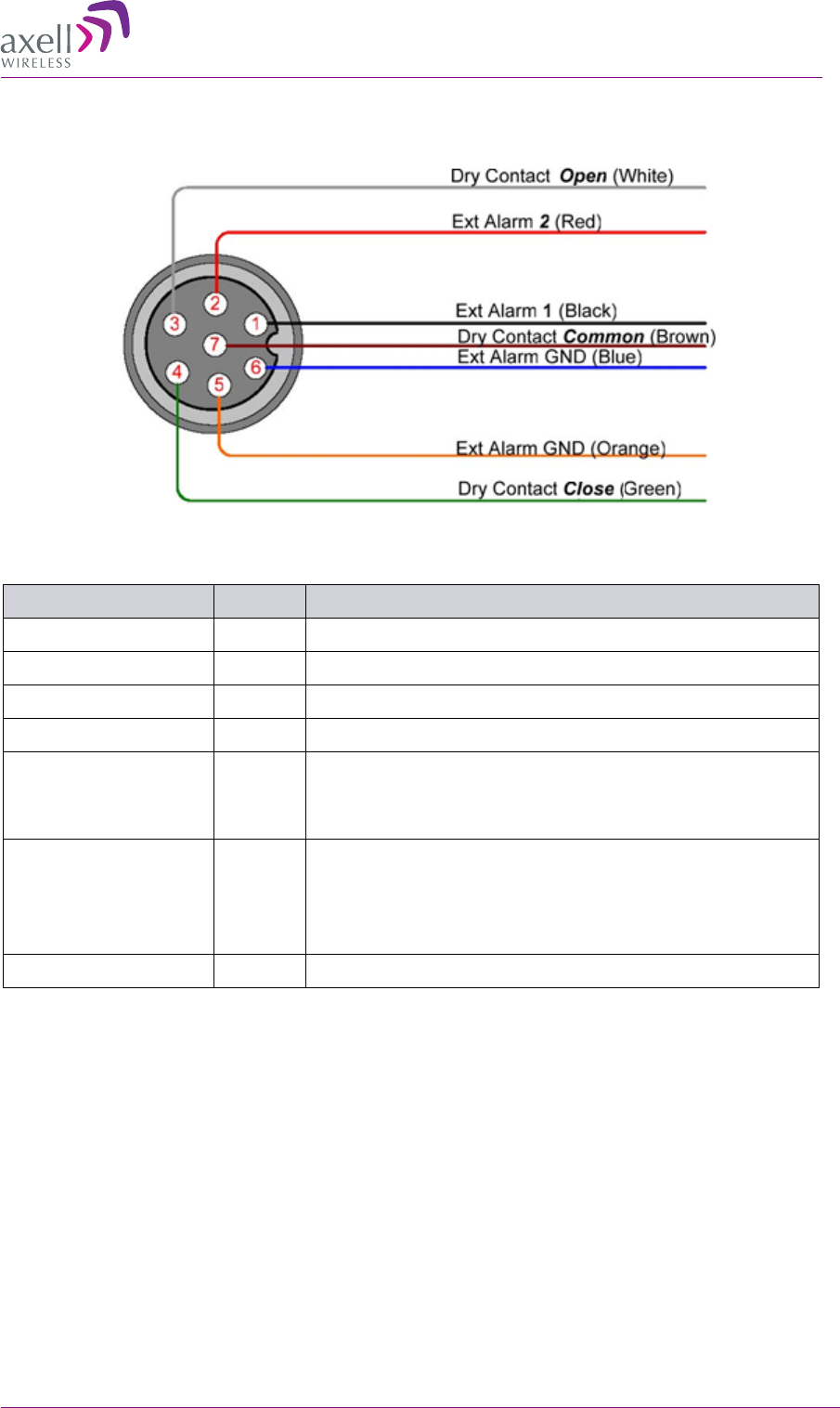
The color configuration of the alarm wires is as follows
The following table provides a description of the Alarm connector pinout and the corresponding
cable wire color-match pin.
Description Pin No. Operation
External Alarm_1 1 Triggers Alarm ID 1 (if set in the External Alarms tab).
GND 5 Ground, galvanic short to Repeater chassis.
External Alarm_2 2 Triggers Alarm ID 2 (if set in the External Alarms tab).
GND 6 Ground, galvanic short to chassis
Dry contact relay
Normally Open (NO)
3 Normally Open to the relay common port. The contact is
open during normal operation closes when either a Major
Alarm is detected or the Repeater is switched off.
Dry contact relay
Normally Closed (NC)
4 Normally Closed to the relay common port. The contact is
closed during normal Repeater operation and opens when
either a Major Alarm is detected or the Repeater is switched
off.
Dry contact-common 7 Dry contact relay common port
3.11.1 Load Restrictions
3.11.1.1 Alarm Dry Contact Output Restrictions
• Maximum switching voltage: 220 VDC, 125 VAC
• Maximum switching current: 2A
3.11.1.2 External Alarm Input Restrictions
• Maximum repetitive reverse voltage: 28 V
• Impedance load: 470 Ohm: 0 = 0V; 1 = 3.8V - 28V
AXELL 3307D REPEATER
PRODUCT DESCRIPTION AND USER’S MANUAL
20 © Axell Wireless Ltd
4
4
I
In
ni
it
ti
ia
al
l
S
Se
et
tu
up
p
a
an
nd
d
C
Co
om
mm
mi
is
ss
si
io
on
ni
in
ng
g
This section provides the setup procedures for the 3307D Repeater. The Repeater is designed for
simple plug-and-play operation, only requiring the setup of a number of parameters (such as DL
Output Power, bandwidth, and gain) through a local Web connection and verifying that the system is
operating properly.
The setup procedure consists of the following steps:
1. Open a local Web session to the Repeater (this requires configuring the communication
parameters of the computer used).
If you are not familiar with the Axell Web Access application, we suggest you quickly review the
section on Navigating the Web GUI Application. It is only a couple of pages and you will find it
useful.
2. Adjust the signal levels and configuring the sub-bands.
3. After the required coverage is attained for the location, verify that no Alarms are generated
before connecting to the main control center.
4. Set the Repeater time and date.
5. Configure the external alarms.
6. Configure the communication and system parameters.
4
4.
.1
1
O
Op
pe
en
n
a
a
L
Lo
oc
ca
al
l
W
WE
EB
B
S
Se
es
ss
si
io
on
n
t
to
o
t
th
he
e
R
Re
ep
pe
ea
at
te
er
r
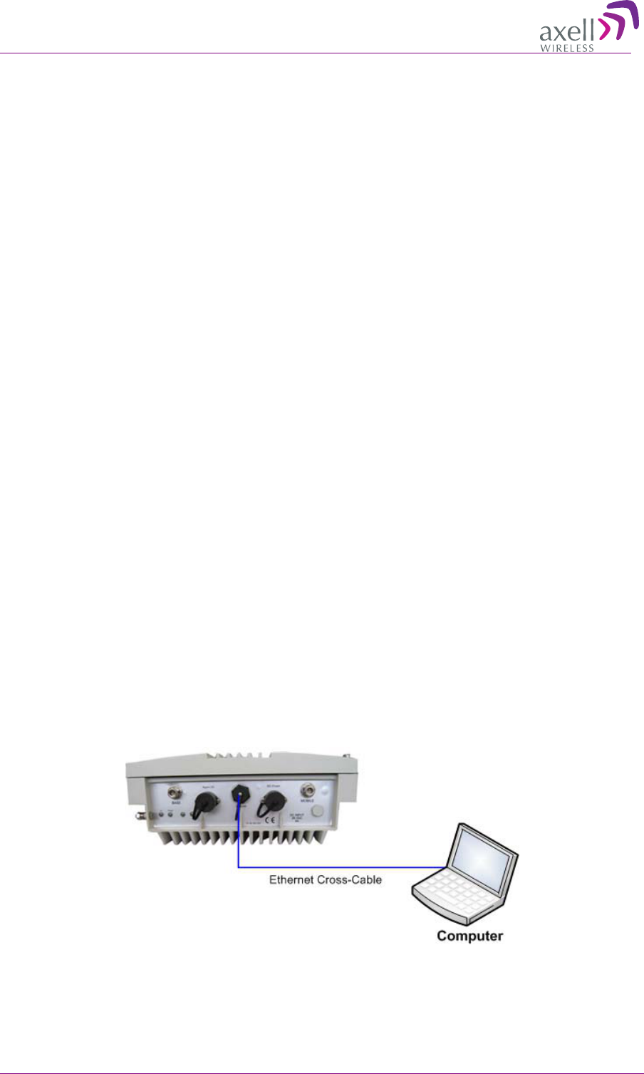
4.1.1 Connecting to the Repeater
To connect Repeater to computer
Interconnect the computer and the Repeaters’ front panel Ethernet ports with the supplied Ethernet
cross-cable as shown below.
Figure 15. Local Ethernet Connection
AXELL 3307D REPEATER
PRODUCT DESCRIPTION AND USER’S MANUAL
© Axell Wireless Ltd 21
4.1.2 Configure the Computer Network Parameters
Configure the computer network parameters to communicate with the Repeater. Note that the
procedure may vary slightly depending on the operating system installed on your computer. The
following procedure is for Windows 7.
To configure the computer’s network parameters:
1. Click the Start menu and choose Control Panel.
2. In the Control Panel, click Network and Internet.
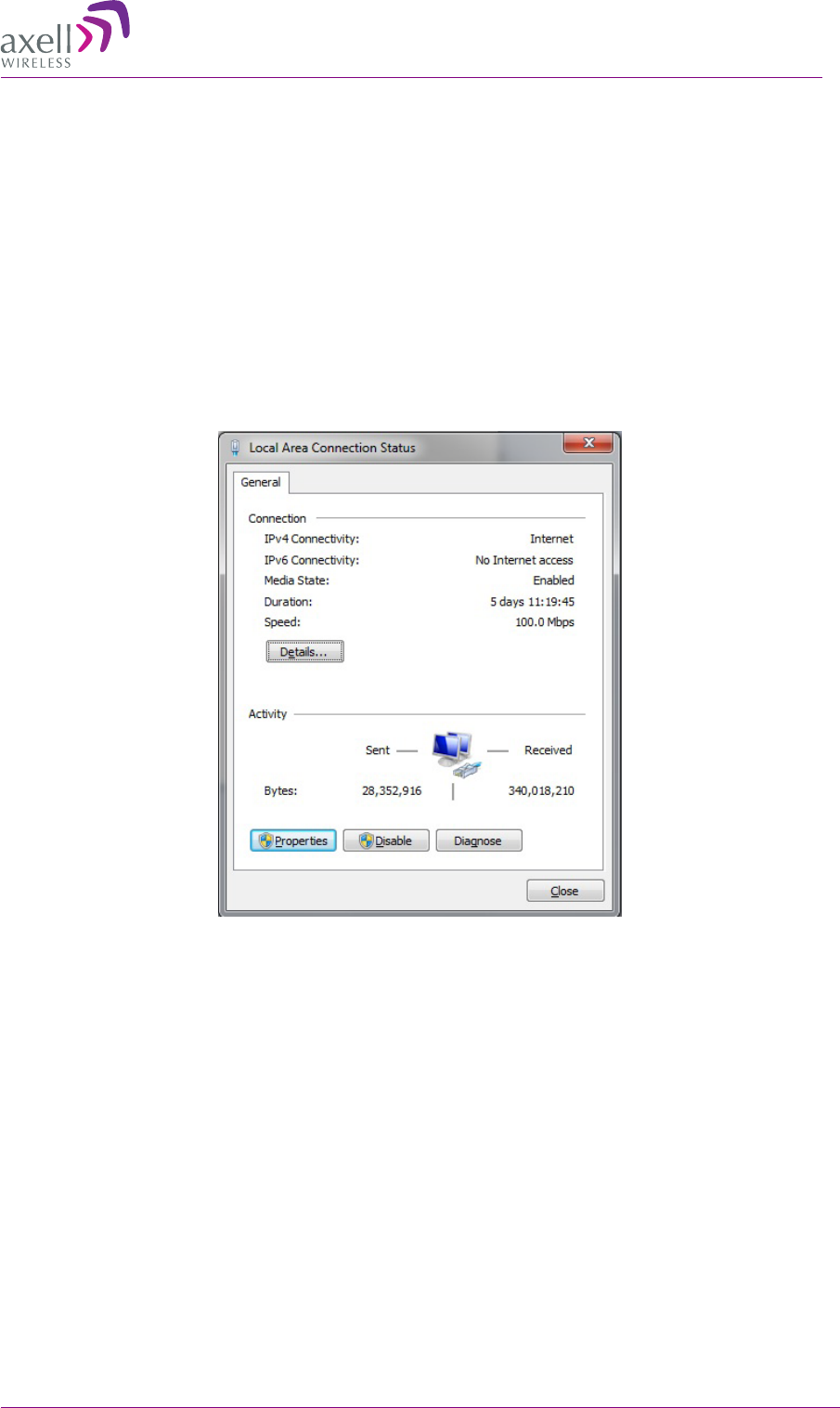
3. Click Network and Sharing Center and then click Local Area Connection.
The Local Area Connections Status dialog appears with the General tab displayed by default.
4. Click the Properties button in the displayed Local Area Connection Status dialog.
AXELL 3307D REPEATER
PRODUCT DESCRIPTION AND USER’S MANUAL
22 © Axell Wireless Ltd
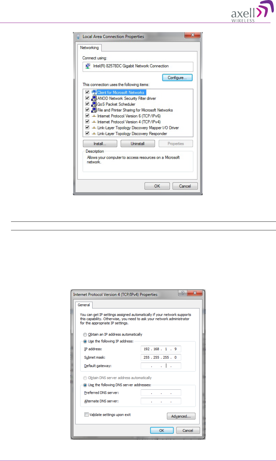
5. In the Items list, double-click the Internet Protocol Version 4 (TCP*IPv4) item. The Internet
Protocol Version 4 (TCP/IPv4) Properties dialog appears.
Note: The Repeater is supplied with the default IP address 192.168.1.253.
6. Assign your computer an IP address in the same subnet, in order to communicate with the unit.
• In the IP address area:
• Enter the IP address 192.168.1.x, where ‘x’ can be any number between 2 and 250
inclusive. For example, (192.168.1.9)
• Define the subnet mask as shown (255.255.255.0)
AXELL 3307D REPEATER
PRODUCT DESCRIPTION AND USER’S MANUAL
© Axell Wireless Ltd 23
• Click OK. The computer communication parameters are now defined and you can
open a session to the Repeater.
4.1.3 Login to the Repeater
NOTE: The Repeater is factory assigned the address 192.168.1.253. Initial login is performed using
this address; however it is recommended to make the necessary modifications according to
information provided by your network administrator.
To login to the Repeater
1. Open one of the Flash-enabled browsers listed in the system requirements.
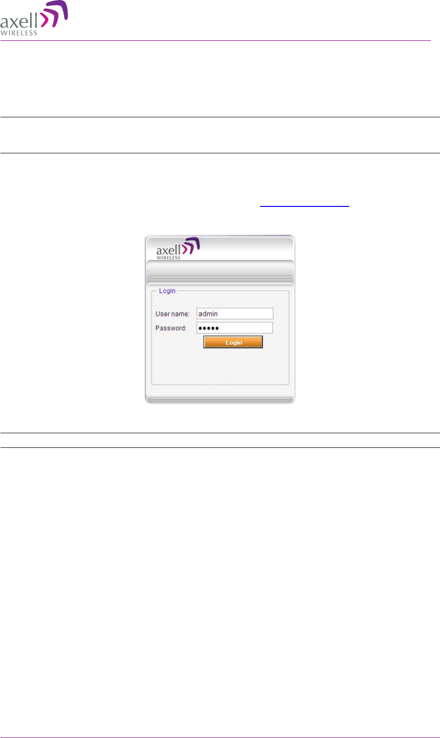
2. In the address line, enter the IP address of the Repeater. http://192.168.1.253. A session will be
established with the Repeater an the login dialog appears.
3. Type the default User Name admin and the default Password admin.
Note that both are case sensitive and must be entered with lower case letters.
4. Click Login. The application main window appears.
5. Quickly review the following section describing the application window and then proceed to
configure the signal levels according to section 4.3 0.
AXELL 3307D REPEATER
PRODUCT DESCRIPTION AND USER’S MANUAL
24 © Axell Wireless Ltd
4
4.
.2
2
N
Na
av
vi
ig
ga
at
ti
in
ng
g
t
th
he
e
W
We
eb
b
G
GU
UI
I
A
Ap
pp
pl
li
ic
ca
at
ti
io
on
n
This section describes how to navigate the Web Management application. The Web Access interface
provides three groups of options, listed in the left side Topology Tree items:
• CMU – management, monitoring , configuration and administration options at the Repeater
level.
• LTE (or band name) – band level RF parameters control and monitoring options.
• Users – user definition and management options and enables changing user passwords.
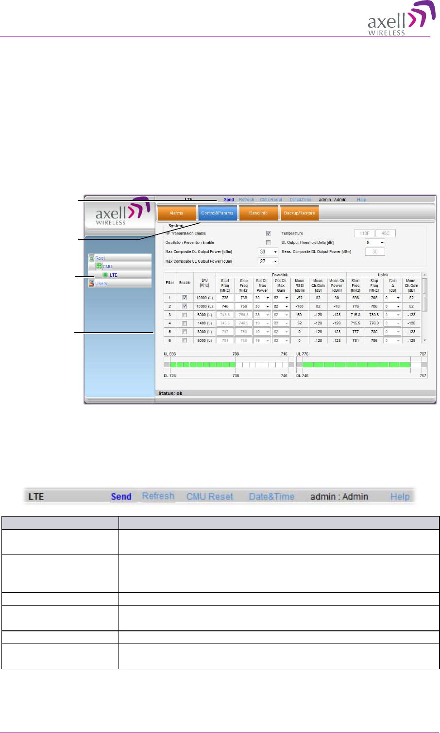
4.2.1 Operation Buttons
The following Operation buttons are available.
Item
Description / Values
Selected Tree Item
Shows the currently selected topology tree item.
Values: CMU, Band (i.e. LTE), Users
Send
Click after completing the new data input and values update in any
screen in order to insert the new values into the Repeater, and
implement the changes
Refresh
Click to refresh the current screen and update the displayed data
CMU Reset
Click to reset the Web Access application, in case of failure or display
problems
Date and Time
Accesses the Repeater Date and Time settings.
Help Click
Help
to display an e-guide line for the system operation. This
Help is general by its nature and some features may not be included.
Topology Tree
Items
Pane related to
selected tab
Operation Buttons
Tabs related to
selected Tree item
AXELL 3307D REPEATER
PRODUCT DESCRIPTION AND USER’S MANUAL
© Axell Wireless Ltd 25
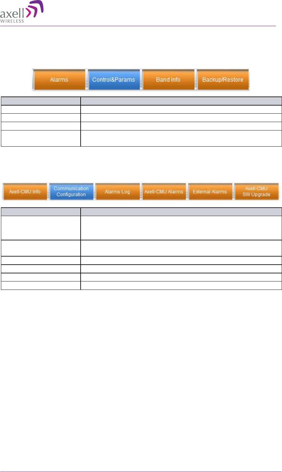
4.2.2 Band Pane and Tabs
The upper area of each selected pane shows the tabs corresponding to the selected band (i.e. LTE).
Item
Description / Values
Alarms
Repeater level alarms.
Control and Params
RF parameters and configuration of sub-channels for the band
Band Info
Information on hardware relevant to this band.
Backup/Restore
Configuration files management options. (configuration files can be
stored on the Repeater for access).
4.2.3 CMU Pane and Tabs
When the CMU item is selected in the Topology Tree, the following menu items are available.
Item
Description / Values
Axell CMU Info
Shows Repeater level information such as SW and HW versions and
identification number. In addition, enables setting minimum alarm
levels.
Axell CMU Configuration
Used to set IP, fault notification and modem communication
parameters
Alarms Log
Log of past and current alarms
CMU Alarms
System alarms
External Alarms
Not relevant for this unit.
CMU SW Upgrade
Options for CMU software upgrade.
4
4.
.3
3
S
Si
ig
gn
na
al
l
L
Le
ev
ve
el
ls
s
a
an
nd
d
C
Ch
ha
an
nn
ne
el
l
C
Co
on
nf
fi
ig
gu
ur
ra
at
ti
io
on
n
This section provides a description of the RF Gain setting criteria (set via the Controls and Params
Pane), a full description of the Control and Params pane, and a step-by-step procedure of the signal
level and channel configuration procedure.
4.3.1 RF Gain Setting Criteria
The RF Gain is set automatically by the Repeater’s SALC function. The function sets the optimum
gain without exceeding the isolation limit.
The gain range is up to 82dB for the LTE band and is set by default to its maximum value.
The gain will then be modified automatically to its optimum value by the SALC mechanism. This
mechanism performs gradual learning of traffic load characteristics and adjusts the Repeater RF Gain
accordingly. (See section 1.3 for more information on the SALC mechanism).
AXELL 3307D REPEATER
PRODUCT DESCRIPTION AND USER’S MANUAL
26 © Axell Wireless Ltd
4.3.2 Adjusting the Signal Levels and Configuring Channels
The Control and Params (parameters) window is used to configure each of the 700 MHz sub-bands
and Max UL/DL Power. This section describes each of the fields.
Up to 8 or 12 sub-bands referred to as filters can be defined, where each sub-band is individually
defined by setting the following:
• Bandwidth (start and stop frequency) - each sub-band can be set over the full LTE for the
following bandwidths: 1.4MHz, 3MHz, 5MHz, 10MHz or 15MHz
• Maximum power
• Maximum gain
• Gain delta
The defined sub-bands are displayed in the lower part of the screen for reference.
To adjust the signal levels and configure the channels
1. In the topology tree, click Root and click LTE.
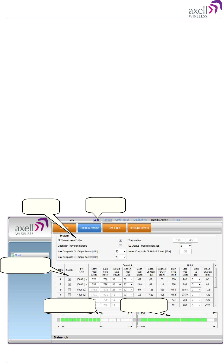
2. Click the Control and Params tab. The corresponding pane appears.
The window is divided into the following areas:
• System – overall parameters for the selected service.
• Filter definitions – used to define up to 8/12 sub-bands and their RF parameters.
• Sub-bands view – graphical display of defined sub-bands for the service. The view is
divided into two: lower A,B,C band (left) and Upper C band (right)
Defined Lower A,B,C
band channels
Defined
Upper C
band channels
Service level
parameters
Click Send with
each change
Sub-band definition
options

AXELL 3307D REPEATER
PRODUCT DESCRIPTION AND USER’S MANUAL
© Axell Wireless Ltd 27
Note: Be sure to click Send with each change.
3. Set the System Level parameters:
• Verify that the RF Transmission Enable parameter is checked.
• Set the Max Composite DL Output Power according to your site requirements and
click Send. The Measured Composite DL Output Power is displayed in the adjacent
field.
If the composite output power exceeds the defined value, the Smart ALC feature begins
working.
• Set the Max Composite UL Output Power according to your site requirements.
Additional parameters (not required for initial setup) are:
• Oscillation Prevention Enable - Enables oscillation detection mechanism that
maintains repeater functionality.
• Temperature - Displays Repeater ambient temperature.
• DL Output Threshold Delta (dB) - the delta from the set Composite Output Power,
below which the alarm 'Donor power is too low' is activated.
For example, if the DL Output Threshold value is set to 8dB, when the Measured
Composite DL output power is 8dB less than the set Composite Output Power, an alarm
is generated.
• Meas. Composite DL Output Power – displays the currently measured output signal
level.
4. To configure each sub-band:
• Checkmark Enable. The configuration parameters in that row will be available.
• In the Downlink area, set the Start and Stop DL Frequency (MHz). (The Uplink Start
and Stop frequencies will be automatically allocated.)
The defined BW will be displayed in the BW KHz column (to the left of the Start
Frequency).
Be sure to choose Start/Stop values that provide any of the following bandwidths:
1.4MHz, 3MHz, 5MHz, 10MHz or 15MHz.
• Set the (Downlink) Max Gain as follows: by default, the MAX Gain (DL) parameter
is set to its highest level (82dB). Change the Channel Max Gain (DL) according to
the measured/calculated input power and isolation measurements.
The recommended Maximum Gain setting is approximately 15 dB less than the isolation
between the service and donor antennas.
5. If the site NOISE LEVEL is high enough to cause interference, adjust the noise level as follows:
• Adjust the Gain Delta parameter – this sets the delta between the uplink and
downlink gain (so the uplink gain is relatively lower than the downlink gain.
• Click Send. The defined sub-band will appear in the display in the appropriate area:
Lower A,B,C (left side) or upper C (right side).
• Repeat the procedure until the desired coverage is achieved.
AXELL 3307D REPEATER
PRODUCT DESCRIPTION AND USER’S MANUAL
28 © Axell Wireless Ltd
6. More information on parameters for the selected sub-band:
• DL Set Ch. Max. Gain Sets the power for the antennas. The value is about 15 dB
less than the isolation between the donor antenna and the mobile antenna.
The Value defined in the DL path is reflected in the UL path, however to define different
UL and DL path values the Gain Delta parameter is used and its defined value is added
to the UL value.
• DL Measured RSSI - measured DL signal.
• DL Measured Ch. Gain - measured DL Gain (dB) for the selected sub-band.
• DL Measured Ch. Power - measured Power (dBm) for the selected sub-band.
• UL Gain Δ - used for noise control. Sets the difference between UL and DL gain.
• UL Measured Ch. Gain - measured UL Gain (dB) for the selected sub-band.
7. Click Send (top window area option).
8. After the channels have been configured and the required coverage is attained for the location,
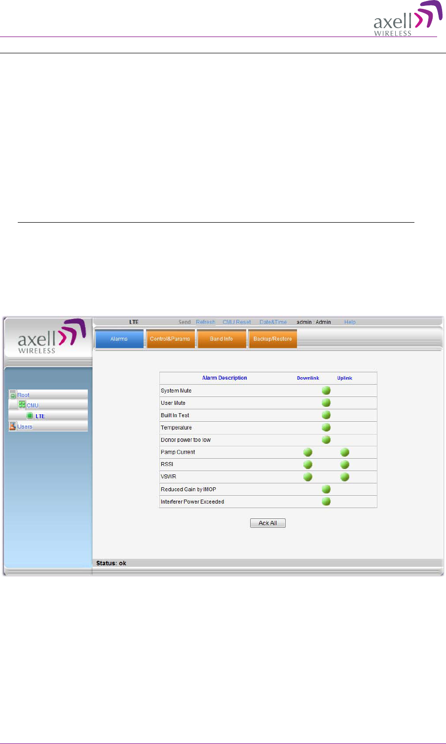
verify that no Alarms are generated:
• Click the Alarms tab
• Verify that all the indicators are GREEN in the Alarms tab.
AXELL 3307D REPEATER
PRODUCT DESCRIPTION AND USER’S MANUAL
© Axell Wireless Ltd 29
4
4.
.4
4
S
Se
et
tt
ti
in
ng
g
D
Da
at
te
e
a
an
nd
d
T
Ti
im
me
e
It is important to set the correct date and time on the unit since this provides the timestamp for each
logged event and alarm.
To set the Repeaters date and time
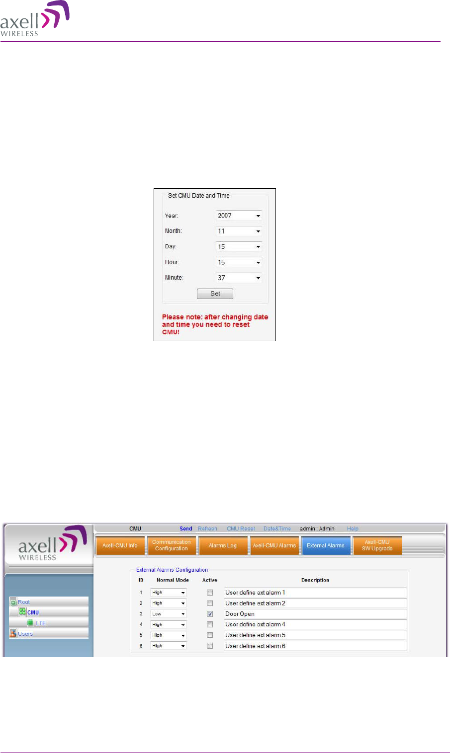
1. Click on CMU in the tree pane.
2. Click on Date & Time in the menu bar. The following dialog appears.
3. Set the date and time parameters and click on Set.
4. Reset the CMU (as described in the following section).
4
4.
.5
5
C
Co
on
nf
fi
ig
gu
ur
ri
in
ng
g
t
th
he
e
E
Ex
xt
te
er
rn
na
al
l
A
Al
la
ar
rm
ms
s
Any connected alarms (section 3.11) must be enabled and configured according to the instructions
provided in this section.
To configure external alarms
1. Click on CMU in the tree pane.
2. Click the External Alarms tab. The following dialog appears.
3. For each connected alarm:
• Checkmark the Active checkbox.
• Set the alarm Normal Mode as High or Low.
• In the Description field, assign the alarm an identifiable name.
AXELL 3307D REPEATER
PRODUCT DESCRIPTION AND USER’S MANUAL
30 © Axell Wireless Ltd
4
4.
.6
6
C
Co
om
mm
mu
un
ni
ic
ca
at
ti
io
on
n
a
an
nd
d
S
Sy
ys
st
te
em
m
P
Pa
ar
ra
am
me
et
te
er
rs
s
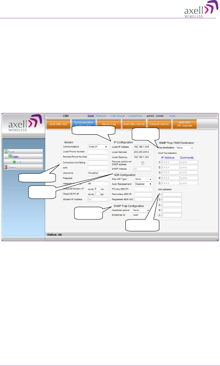
The Communication Configuration tab provides the Modem, IP, AEM and SNMP trap configuration
parameters.
This section describes how to access the dialog. The following sub-sections provide detailed
information on each configuration option.
4.6.1 The Communication Configuration Tab
To access the Communication Configuration tab
In the left tree pane, click CMU. From the available tabs in the work area, choose the
Communication Configuration tab.
4.6.2 IP Address Configuration
The Repeater supports both Static and DHCP addresses. A unique technology enables applying both
types to the same Ethernet port. Both addresses may enable local and remote management.
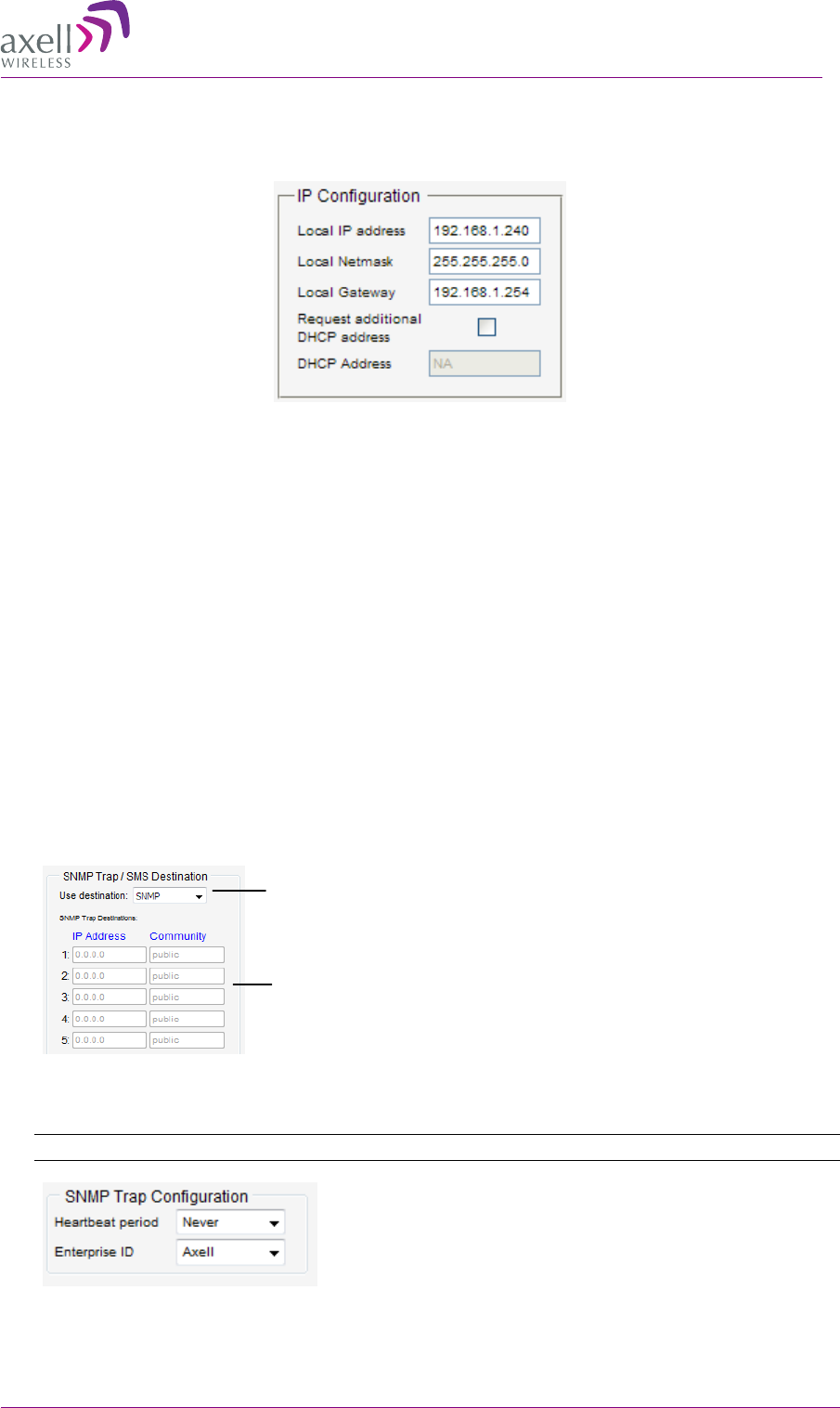
• Local IP Address – Static IP assigned by the user to the system. The default Static IP address is
192.168.1.253. It is highly recommended to preserve this setup. In case of a change, make sure
you record the newly assign IP.
• DHCP Address – address assigned by DHCP server – used for remote management via an
Ethernet connection.
To assign the unit IP address
1. Access the Communication Configuration tab according to section 4.6.1.
2. To assign the unit addresses:
• Local address - in the IP Configuration area, assign the unit the IP address, Netmask
and Gateway parameters provided by your system administrator.
IP Address settings
Modem parameters
SNMP IP
destinations
Trap sending
frequency
SMS destinations
mobile numbers
AEM
configuration
AXELL 3307D REPEATER
PRODUCT DESCRIPTION AND USER’S MANUAL
© Axell Wireless Ltd 31
• DHCP server address – checkmark the option Request Additional DHCP Address.
The assigned address can be seen in the DHCP Address field.
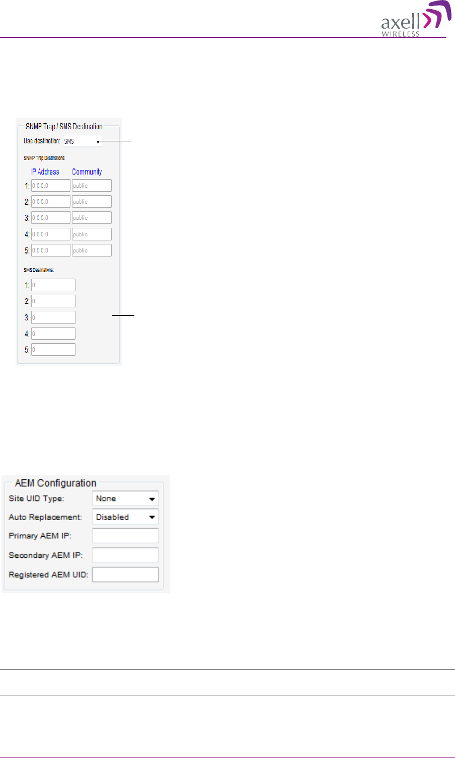
4.6.3 Configuring Notification Method - SNMP Trap or SMS
The Repeater can be configured provide fault notification either by sending traps to defined IP
addresses or by sending an SMS message to configured destinations (only one option can be
selected).
4.6.3.1 Configuring SNMP Trap Destinations
You may configure traps to be sent to five destination addresses each time a fault is triggered. The
traps are sent at the defined heartbeat frequency.
To set SNMP Trap Destination parameters
1. In the Use Destination field, select the SNMP option
2. For each destination:
• Enter the IP Address (where the IP addresses should be in the same subnet as the
repeater).
• Define the Community names (default = public) of the computers to which traps will
be sent.
3. In the SNMP Trap Configuration area, in the Heartbeat Period field, define the frequency (in
minutes) at which traps will be sent.
NOTE: It is recommended to maintain the Enterprise ID as Axell.
4. Click Send.
Select
SNMP
option from
drop-down list
Define up to five SNMP
destination addresses
AXELL 3307D REPEATER
PRODUCT DESCRIPTION AND USER’S MANUAL
32 © Axell Wireless Ltd
4.6.3.2 Configuring SMS Notification Destinations
You may configure up to five SMS destinations (mobile numbers).
To set SMS Destination parameters
1. In the Use Destination field, select the SMS option from drop-down list.
2. Define up to five SMS destinations (for example, + xxx541234567):
3. Click Send.
4.6.4 AEM (Axell Element Manager) Configuration
Configure the AEM parameters provided by the system administrator so that the 3307D Repeater is
integrated in the network and can be centrally managed.
4
4.
.7
7
M
Mo
od
de
em
m
C
Co
om
mm
mu
un
ni
ic
ca
at
ti
io
on
n
S
Se
et
tu
up
p
The Repeater modem supports both a Packet Switch and a Direct Circuit Switch connection.
This section describes how to configure the modem according to the required communication mode.
NOTE: For GPRS modems, it is assumed that the SIM card is already installed according to section
3.6.
Define the SMS
destinations (mobile
Select SMS option from
drop-down list
AXELL 3307D REPEATER
PRODUCT DESCRIPTION AND USER’S MANUAL
© Axell Wireless Ltd 33
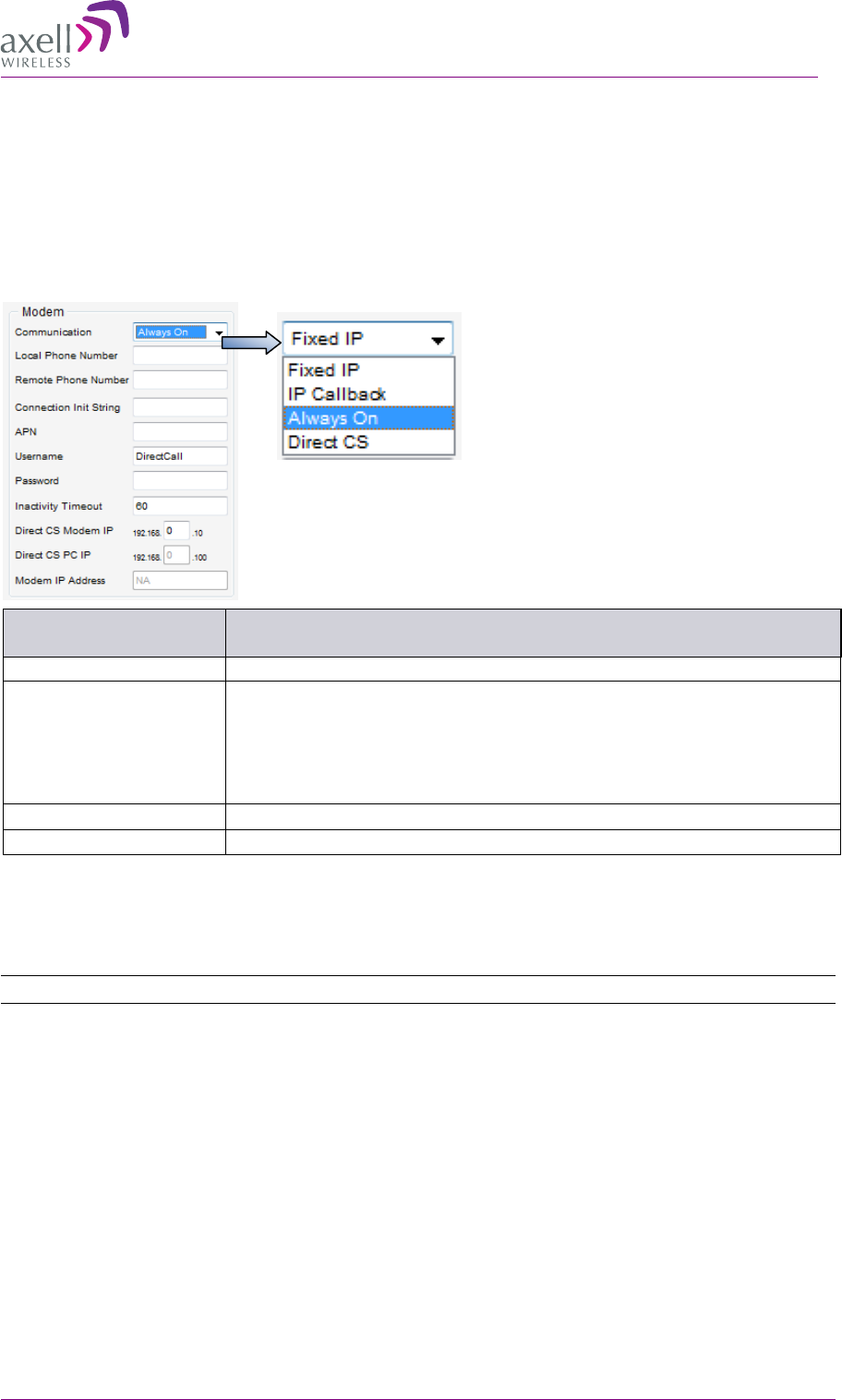
4.7.1 Available Modem Parameter Options
To define the modem parameters
Click CMU in the left tree pane and select the Communication Configuration pane.
In the Modem area, select the Communication mode and define any additional parameters
according to the table below. (Any defined fields in the figure below are only an example!)
In the communication
field, select …
For this communication mode.
Fixed IP.
Modem OFF
Always ON.
Packet Switch mode. (CDMA, GPS/GPRS, etc.).
For GPRS Modem, see section 4.7.2.
For CDMA modem configuration, see section 4.7.4
NOTE: After the modem connects to the network, the Modem IP
Address is displayed.
Direct CS.
Direct Circuit Switch, see section 4.7.3.
IP Callback
Special mode for specific installation types.
4.7.2 GPRS Modem
For GSM/GPRS communication, GSM/GPRS modems are installed. These modems support
both a Packet Switch and a Direct Circuit Switch connection.
NOTE: It is assumed that the SIM card is already installed according to section 3.6
To define the modem parameters
1. Click CMU in the left tree pane and select the Communication Configuration pane.
2. In the Modem area, set the Communication mode as Always ON.
3. Define any additional parameters as required by your operator.
4.7.3 Direct Circuit Switch Connection
A. On the Repeater, set the Repeater Modem parameters (above) as follows:
• Communication - Direct CS
• To provide security, set the User Name and Password for the repeater (the same User
Name and Password will be defined on the dial-up connection).

AXELL 3307D REPEATER
PRODUCT DESCRIPTION AND USER’S MANUAL
34 © Axell Wireless Ltd
• You may modify (optional) the Direct CS Modem IP – this is the Web address used
to open a Repeater session. Otherwise, the default displayed value can be used.
B. On your computer, set up a dial-up connection as follows:
1. Via Network Connections, create a Dial-up connection on your computer (Connect using a dial-
up modem). The procedure may vary slightly depending on your Operating System.
2. Define the parameters as follows:
• ISP connection name – user defined, recognizable name for this connection for future
reference.
• Phone Number – the number corresponding to the SIM card installed on the Repeater.
• User Name and Password – the User Name and Password (if assigned) that you
allocated in the Modem parameters in the Communication dialog (see previous
section).
C. Open a session to the Repeater:
1. On your computer, click the relevant dial-up connection item or the icon, to open a dial-up route
to the Repeater.
1. Open a Web Browser and enter the Direct CS Modem IP that is defined in the Modem
parameters on your Repeater. A session will be opened to the Repeater.
AXELL 3307D REPEATER
PRODUCT DESCRIPTION AND USER’S MANUAL
© Axell Wireless Ltd 35
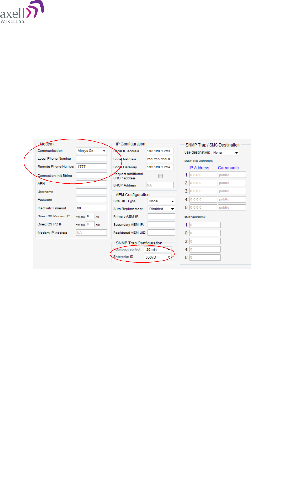
4.7.4 CDMA Modem
4.7.4.1 Configuring for CDMA Modem
To configure for a CDMA modem
1. In the Modem area above, verify that:
• Modem Communication = Always On
• Remote Phone Number = #777 (Verizon)
• Connection Init String = empty field (blank)
• Enterprise ID = 3307.
2. Activate the modem in the Verizon network according to the following section.
AXELL 3307D REPEATER
PRODUCT DESCRIPTION AND USER’S MANUAL
36 © Axell Wireless Ltd
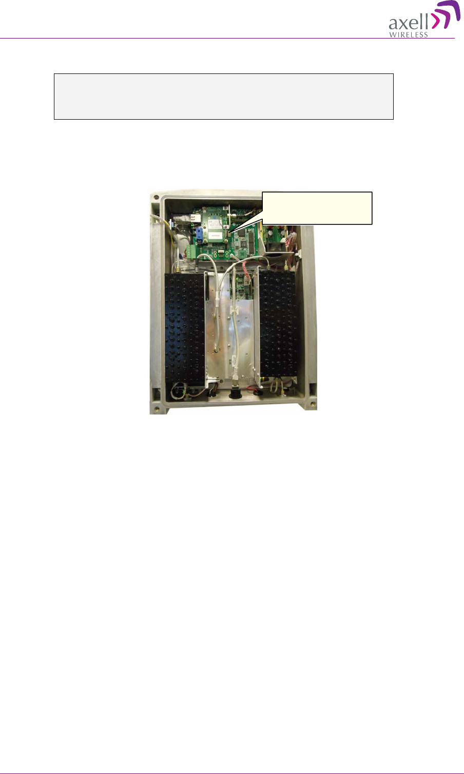
4.7.4.2 Activating the modem in the Verizon network
WARNING!!! SETTINGS OF THE MODEM ARE SENSITIVE TO CHANGES.
INSERT VALUES AND PARAMETERS WITH PARTICULAR CARE IN ORDER TO
ENABLE THE REMOTE CONNECTION.
Below is the activation procedure for the modem in the Verizon Wireless Network.
1. Open the Repeater and connect the RS-232 cable (provided in the accessory kit) to the CMU
card.
2. Open HyperTerminal with (or eqvivalent program)
3. Set connection speed to 115,200, no flow control.
4. Type AT and you should get a response OK.
5. Use the command ATD*22899; (ensure there is a semi-colon “;” after the dial string, otherwise
you will make a circuit data call). This will start your OTASP (Over-The-Air, Service
Provisioning) session.
The following messages should be displayed:
• +WOT1: “Programming in Progress”
• +WOTS: “SPL unlocked”
• +WOTP: “PRL download OK”
• +WOTM: “MDM download OK”
• +WOTC: “Commit successful”
• +WOT2: “Programming Successful!”
IMPORTANT* After programming, remove the RS-232 cable for proper modem function on
the Verizon network.
6. After a few minutes, a Modem IP Address should appear on the CMU GUI screen. This indicates
the modem is functioning on the Verizon Network. The module is then set up for both voice and
data.
RS-232 connection for
modem activation
AXELL 3307D REPEATER
PRODUCT DESCRIPTION AND USER’S MANUAL
© Axell Wireless Ltd 37
5
5
A
Ad
dm
mi
in
ni
is
st
tr
ra
at
ti
iv
ve
e
O
Op
pe
er
ra
at
ti
io
on
ns
s
The following administrative operations are described in this section:
• User Management – defining and changing users and passwords.
• Viewing the Repeater information such as software and hardware versions, serial number, etc.
• Repeater software upgrade
• Configuration files backup and restore
5
5.
.1
1
U
Us
se
er
r
M
Ma
an
na
ag
ge
em
me
en
nt
t
This section describes how to perform the user management operations. By default, two users
belonging to one of three authentication levels are defined on the Repeater.. You may add new users,
modify or delete existing users.
5.1.1 User Levels
Two user levels are available:
• Admin – has access to all administration and configuration options, including user management.
(Default Password admin and default User Name admin.)
• Operator – has access to all configuration options except for the Users list or the Loaders screen.
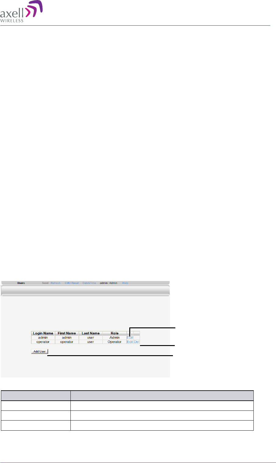
5.1.2 Viewing the List of Defined Users
To display the User Administration pane
From the Tree Pane, select Users. The list of users is displayed in the Configuration Pane according
to the identifying information and authentication level (Role).
The following table provides a description of the Users dialog options.
Option Description
Add User (button) Adds a new user with to user defined access level and password.
Del(ete) Deletes a selected user from the list.
Edit Enables changing the definitions of an existing user.
Edit user
Delete user
Add user
AXELL 3307D REPEATER
PRODUCT DESCRIPTION AND USER’S MANUAL
38 © Axell Wireless Ltd
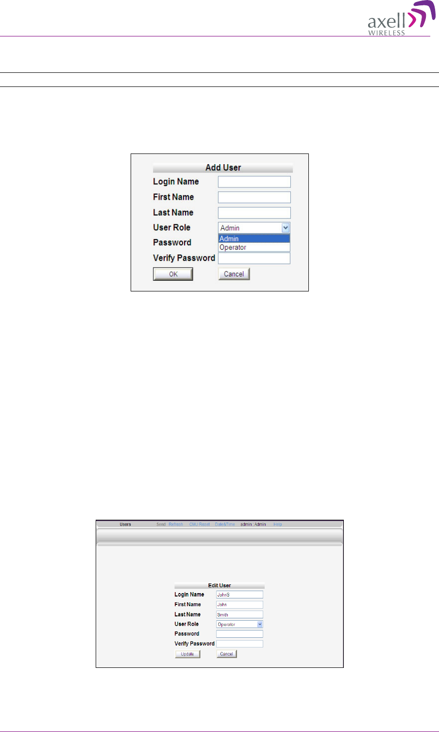
5.1.3 Adding Users
NOTE: User name and password entries are case sensitive.
To add a user
1. From the Tree Pane, select Users. The list of users is displayed in the User's Pane.
2. From the User's Pane, click Add User. The Add User dialog box is displayed.
3. Enter the Login Name – name used by user to login.
4. Type the user's First Name and Last Name – used to identify the user.
5. Select the User Role – access level. This defines the operations that the user will be able to
perform.
6. Enter the Password and in Verify Password enter the password again for verification.
7. Click OK.
5.1.4 Editing a User
To modify user definitions
1. From the Tree Pane, select Users. The list of users is displayed in the User's Pane.
2. Select the User to be edited in the list.
3. Click Edit. The user definitions dialog appears.
4. Make the required changes and click OK.
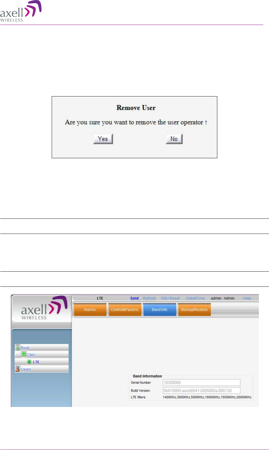
AXELL 3307D REPEATER
PRODUCT DESCRIPTION AND USER’S MANUAL
© Axell Wireless Ltd 39
5.1.5 Deleting a User
To delete a user
1. From the Tree Pane Select Users. The list of users is displayed in the User's Pane.
2. Select the User to be deleted in the list.
3. From the User's Pane, click Del. An authorization message dialog box is displayed.
4. Click Yes. The User’s name is removed from the list.
5
5.
.2
2
V
Vi
ie
ew
wi
in
ng
g
B
Ba
an
nd
d
I
In
nf
fo
or
rm
ma
at
ti
io
on
n
Use the Band Information screen to view the hardware and software versions of the Axell 3307D
Repeater band and to assign it a serial number.
NOTE: Grayed-out fields indicate that the display is Read-only. Active fields indicate that the
parameter values can be defined.
To access the Band Information window
1. From the Tree Pane, select LTE.
2. Select the Band Info tab. The relevant parameters are displayed.
NOTE: The Serial Number field can be used to assign the module a recognizable name
corresponding to the technology.
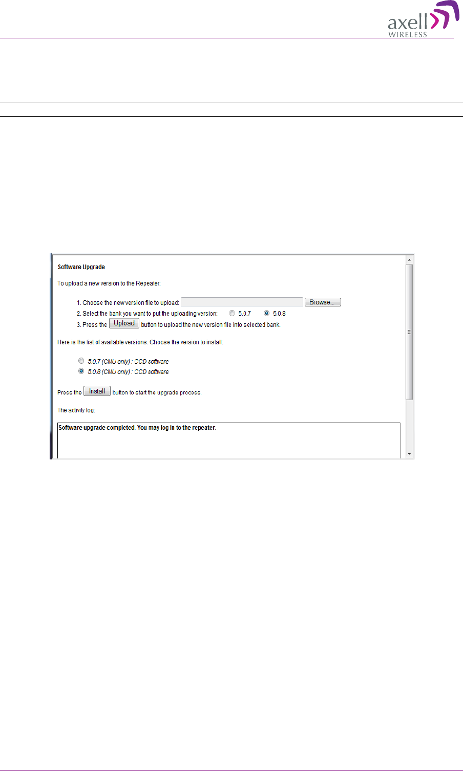
AXELL 3307D REPEATER
PRODUCT DESCRIPTION AND USER’S MANUAL
40 © Axell Wireless Ltd
5
5.
.3
3
R
Re
ep
pe
ea
at
te
er
r
S
So
of
ft
tw
wa
ar
re
e
U
Up
pg
gr
ra
ad
de
e
The procedure described in this section is used to upgrade the repeater CMU.
Note: This procedure is performed for every new management version.
The CMU (Repeater) SW upgrade procedure consists of loading the available updated versions and
installing it in the Repeater.
To Upgrade the CMU SW
1. From the Tree Pane, select CMU.
2. Select the Axell CMU SW Upgrade tab. The CMU SW Upgrade screen shown below appears.
3. Choose the version to upload and perform the procedure according to the instructions in the
screen.
5
5.
.4
4
B
Ba
ac
ck
ku
up
p/
/R
Re
es
st
to
or
re
e
o
of
f
R
Re
ep
pe
ea
at
te
er
r
C
Co
on
nf
fi
ig
gu
ur
ra
at
ti
io
on
n
The 3307D Web GUI management application enables the backup and restore of the repeater
configuration files. The procedures are performed via the Backup/Restore tab.
A number of configuration files can be stored on the Repeater for access at any time.
You can perform the following operations:
• Backup of the currently active configuration
• Restoring a previously saved file
• Uploading a configuration file from another location to the Repeater
• Downloading a configuration file from the Repeater to another location
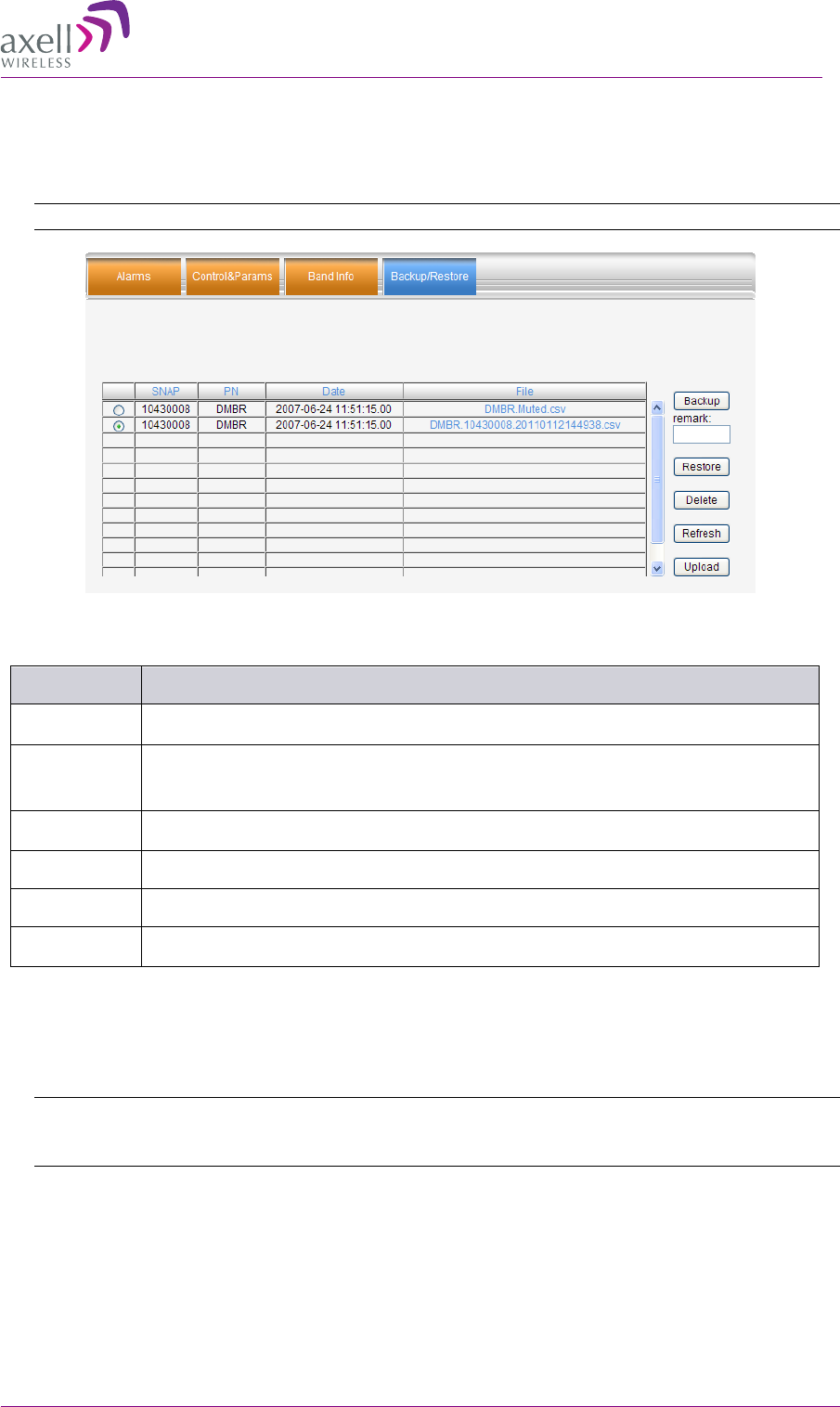
AXELL 3307D REPEATER
PRODUCT DESCRIPTION AND USER’S MANUAL
© Axell Wireless Ltd 41
To access Backup/Restore tab
1. From the Tree Pane, select the LTE (band) item.
2. Select the Backup/Restore tab. The following tab appears.
Note: The following figure is only an example of the Backup/Restore tab.
The following table provides a description of the available options (buttons) in the Backup /Restore
tab shown above.
Button Description
Backup Used to backup the current repeater configuration. See section 5.4.1.
Remark Used to assign the repeater configuration file (to be backed up) a recognizable
name. See section 5.4.1.
Restore Used to restore previous repeater configuration. See section 5.4.2.
Delete Select file from list and click Delete to remove.
Refresh
Click Refresh to list of available configuration files
Upload Used to upload new configuration file to repeater. See section 5.4.3.
5.4.1 Backup of Repeater Configuration
To perform backup procedure
1. To assign the configuration file a recognizable name, enter a name in the remark field.
Note: This must be performed before performing the backup operation; otherwise the file will
automatically be assigned a name according to the backup date and unit ID.
The name cannot be modified once the backup has been performed.
2. Click the Backup button located on the right-hand side of the tab.
3. The file will be added to the table displayed in the Backup/Restore tab.

AXELL 3307D REPEATER
PRODUCT DESCRIPTION AND USER’S MANUAL
42 © Axell Wireless Ltd
5.4.2 Restoring Previous Repeater Configuration
To restore previous configuration
1. Select the required configuration file (enable corresponding radio button) from the available list
in the Backup/Restore tab.
2. Click the Restore button.
3. Click on the Control and Params tab and verify that the required configuration settings have
been restored.
5.4.3 Uploading New Configuration File to Repeater
To upload configuration file to Repeater
1. Click the Upload button.
2. Select the file from the Browse dialog and click Open.
3. The file appears in the list displayed in the Backup/Restore table.
5.4.4 Saving Configuration File to Computer
To save a configuration file from the available list in the Backup/Restore table to a location in a
connected computer:
1. Select file from list.
2. Click the link in the File column.
3. Select the location in the Browse dialog.
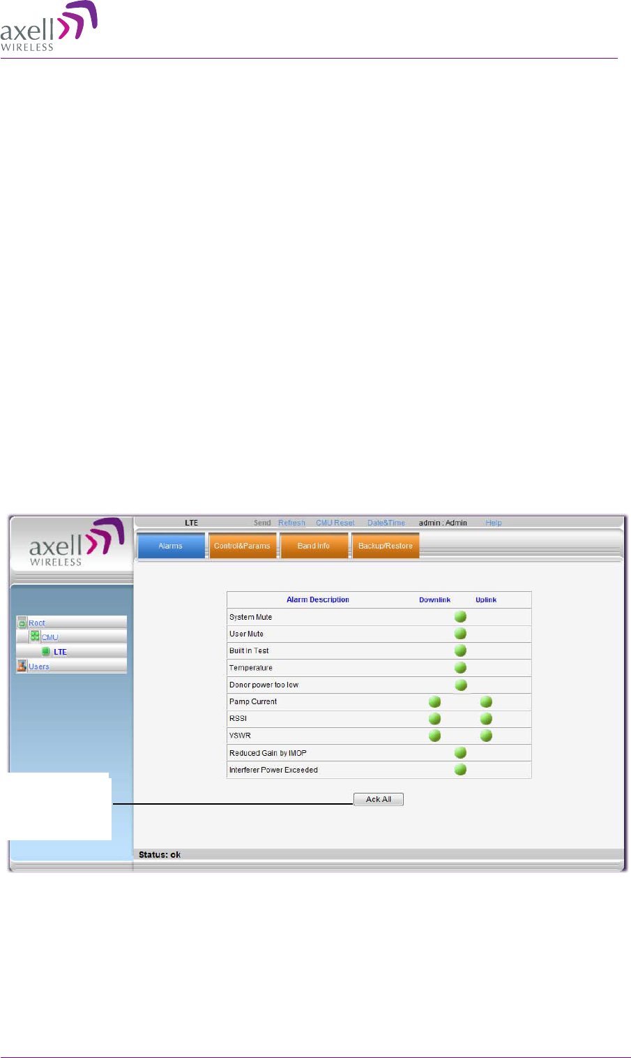
AXELL 3307D REPEATER
PRODUCT DESCRIPTION AND USER’S MANUAL
© Axell Wireless Ltd 43
6
6
M
Mo
on
ni
it
to
or
ri
in
ng
g
a
an
nd
d
T
Tr
ro
ou
ub
bl
le
es
sh
ho
oo
ot
ti
in
ng
g
3307D provides three types of indications of Repeater failure:
• Alarms screen in Web access application
• Alarms Log – used to view a record of past generated alarms
• Status LEDs on Repeater front panel
The following sections provide a description of the troubleshooting procedures according to the
Repeater LED indicators and the Web access Alarms.
6
6.
.1
1
R
Re
ep
pe
ea
at
te
er
r
A
Al
la
ar
rm
ms
s
a
an
nd
d
T
Tr
ro
ou
ub
bl
le
es
sh
ho
oo
ot
ti
in
ng
g
The Alarms tab provides the alarms generated by the Repeater, enabling the user to monitor the
system operation.
To access the Alarms window
From the Tree Pane, select the LTE item and choose the Alarms tab. The relevant parameters are
displayed.
Click Ack All
but
ton to reset
the alarms

AXELL 3307D REPEATER
PRODUCT DESCRIPTION AND USER’S MANUAL
44 © Axell Wireless Ltd
The following table provides a description of the displayed alarms.
Alarm
Fault, most probable cause and recommendation
System Mute Generates an alarm when Repeater amplification is muted (automatically)
User Mute Repeater amplification is muted (manually) as a result of an operator action.
Built In Test Self test.
Temperature High unit temperature.
Most probable cause: Excessive heat.
Check the Repeater case for external causes (sun, hot environment, air flow
is blocked). Eliminate the reason for excessive heat
Donor Power Too
Low
Generates an alarm when the Pre Amplifier current exceeds the allowed
limits
Fault in the DL or UL path.
Most probable cause: Downlink (Uplink) power amplifier module outputs a
low current.
Check the LEDs in the Repeater
PAmp Current
Generates an alarm when the Power exceeds the allowed limits.
Fault in the DL or UL path.
Most probable cause: Downlink (Uplink) power amplifier module
outputs a low current.
Recommendation: Check the LEDs in the Repeater
RSSI
Fault in the DL or UL path
Most probable cause: caused by a excessively high input signal
Recommendation: Check the LEDs in the Repeater
VSWR
This alarm is triggered when the return loss of the Downlink antenna or
cable connection exceeds 3 dB (VSWR 6:1).
This alarm provides an indication of the status of the cable connected to
the antenna. If a cable is defective, the VSWR is decreased and the
alarm is triggered.
Reduced Gain by
IMOP
Shows when the IMOP mechanism was activated in order to respond to
detected oscillations.
GREEN – normal operation – no oscillations were detected.
RED – oscillations were detected and the system reduced gain in order
to eliminate the oscillations.
Check the Donor and Mobile antenna installations for isolation. After
isolation is within the required levels, the system will automatically
increase gain (since it will no longer affect oscillations and) and the
LED will turn GREEN.
Interferer Power
Exceeded
Indicates if there is any external interference at a level that may affect the
operation of the unit.
Green – low or no interference. Unit operation is not affected.
Red – high external interference that may affect the operation of the unit. It
is recommended to identify the source of the interference and distance the
source or the unit from each other.
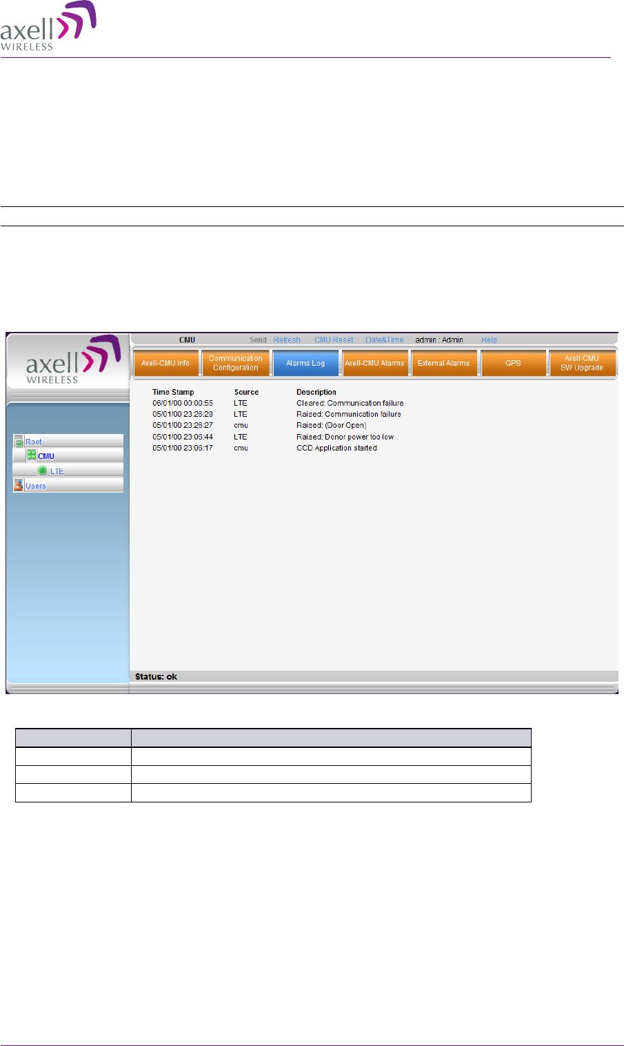
AXELL 3307D REPEATER
PRODUCT DESCRIPTION AND USER’S MANUAL
© Axell Wireless Ltd 45
6
6.
.2
2
V
Vi
ie
ew
wi
in
ng
g
t
th
he
e
A
Al
la
ar
rm
ms
s
L
Lo
og
g
The Alarms Logs screen lists the alarms (events) that have occurred. The CMU maintains log files
listing every alarm triggered and in the Repeater. This screen provides an analysis tool to get
information of any event that has occurred, its originator, when, if they return, and their type.
Note: Set the clock in order to synchronize the events time of occurrence. Click on Date & Time.
To view the CMU log screen:
1. Open and login to the Web application.
2. From the Tree Pane, select CMU.
3. Click Alarms Logs. CMU displays the Alarms Log Table.
Item
Description
Time Stamp
The date and time the alarm was created
Source
ID of Network Element
Description
Description of event that caused the alarm

AXELL 3307D REPEATER
PRODUCT DESCRIPTION AND USER’S MANUAL
46 © Axell Wireless Ltd
6
6.
.3
3
3
33
30
07
7D
D
L
LE
ED
D
T
Tr
ro
ou
ub
bl
le
es
sh
ho
oo
ot
ti
in
ng
g
The 3307D Repeater Power LED on its front panel (see 1.4) can be used for troubleshooting. The
following table provides a description of the DL and Power LED troubleshooting procedures.
LED Color Status, Probable Cause and Recommendation
Service Green Normal operation
Blinking - DL power below threshold---
Red Steady - Major error. Replace the Repeater.
Blinking – service muted by user.
Orange Blinking - service initiating on power up or reset.
Steady – high DL/UL signal or VSWR. This may be due to
isolation problem or temperature. Check gain of
repeater. If gain is minimum, then it is likely an
isolation problem -> improve the isolation.
Reset the Repeater by turning if off and on again. If the
fault continues, replace the unit.
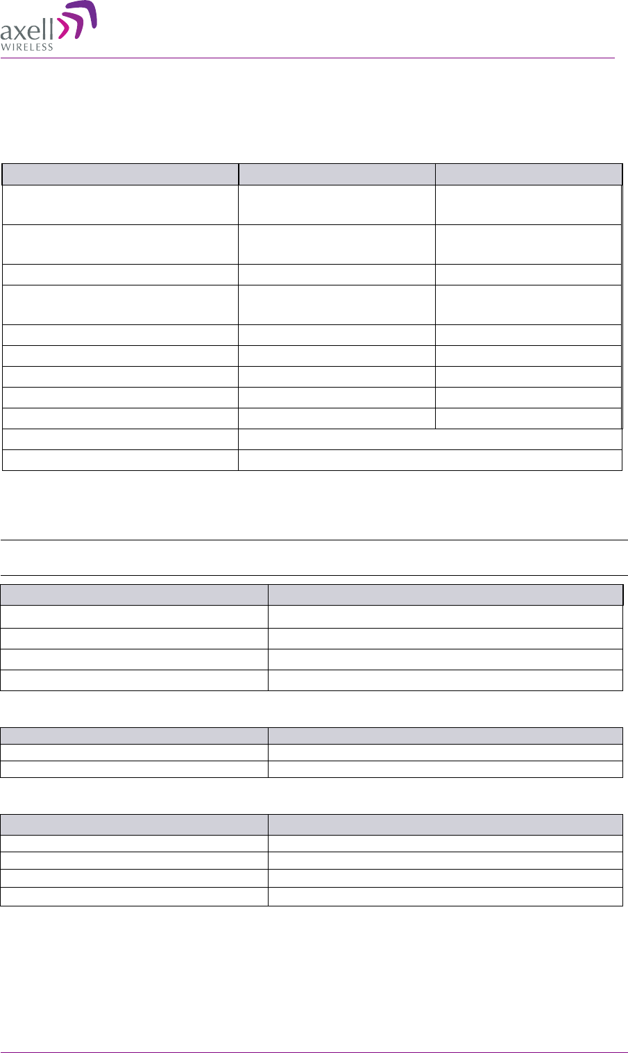
AXELL 3307D REPEATER
PRODUCT DESCRIPTION AND USER’S MANUAL
© Axell Wireless Ltd 47
Appendix: 3307D Specifications
RF Per Band
Parameters DL UL
Frequency Range (MHz) L728-746
U746-757
L698-716
U776-787
Selectable Sub-Bands
(Model dependent)
8 to 12 (model dependent)* 8 or 12 (model dependent)*
Passband Gain (max) 82 ±2 dB dB 82 ±2 dB dB
Passband Ripple 2dB p-p max for BW<10MHz
4dB p-p max for BW≥10MHz
2dB p-p max for BW<10MHz
4dB p-p max for BW≥10MHz
Gain Adjust Range (in 1dB steps) 0-25 dB 0-25 dB
Composite Output Power +33dBm +27dBm
Attenuation range 0 to 30 dB, in 1 dB step 0 to 30 dB, in 1 dB step
Noise Figure @ Maximum Gain (typical)
5 dB 4 dB
Propagation Delay < 6 µsec < 6 µsec
Channel Allocation Adjustable, Non Contiguous
Conformance Standard ETSI EN 300 609-4, GSM11.26, 3GPP TS 25.106
*Supports any BW option 2.5 MHz - 20 MHz in 2.5MHz step by setting the start-stop frequency
Power Supply
Note: Unit is connected to main AC outlet, where the AC voltage is converted to DC (via AC to DC
converter preassembled on the bracket) for connection to the unit front panel DC connector.
Parameter Description
Power Supply AC 110V-220V 50/60Hz
Power Consumption Max 120 W
Total RF Input Power (No Damage) + 10 dBm
Impedance Level 50 Ohm
Mechanical Specifications
Parameter
Description
Size W x H x D
305 mm x 375 x 205 mm (12” x 14.8” x 8.1”)
Weight
14Kg (30.8 lbs) max.
Environmental Specifications
Parameter Description
Environmental conditions
IP65
Operating temperature
-10 to +50
°
C (14 to +122
°
F)
Storage temperature
-40°F to 185°F (-40°C to +85°C)
Humidity
85%