PBE Europe as Axell Wireless DMBA30073008PS Class A Booster User Manual Revised Users manual
Axell Wireless Class A Booster Revised Users manual
Contents
- 1. User manual
- 2. Revised Users manual
- 3. Revision2 of User manual
Revised Users manual
AXELL D-MBR 3007-3008-PS NFPA REPEATER
PRODUCT DESCRIPTION AND USER’S MANUAL
SMR 700/800 Digital Multi-Channel IP65
(NEMA 4) Band Selective Repeater
PRODUCT DESCRIPTION AND USER’S MANUAL
for AXELL D-MBR 3007-3008-PS NFPA REPEATER
UMCD00013 Rev 2.2
D-MBR 3007-3008 PS NFPA
AXELL D-MBR 3007-3008-PS NFPA REPEATER
PRODUCT DESCRIPTION AND USER’S MANUAL
II UMCD00013 Rev 2.2 © Axell Wireless Ltd
Copyright © 2014 Axell Wireless Ltd
All rights reserved.
No part of this document may be copied, distributed, transmitted, transcribed, stored in a retrieval system, or
translated into any human or computer language without the prior written permission of Axell Wireless Ltd.
The manufacturer has made every effort to ensure that the instructions contained in this document are adequate
and free of errors and omissions. The manufacturer will, if necessary, explain issues which may not be covered
by this document. The manufacturer's liability for any errors in the document is limited to the correction of errors
and the aforementioned advisory services.
This document has been prepared to be used by professional and properly trained personnel, and the customer
assumes full responsibility when using them. The manufacturer welcomes customer comments as part of the
process of continual development and improvement of the documentation in the best way possible from the
user's viewpoint. Please submit your comments to the nearest Axell Wireless sales representative.
Contact Information
Headquarters Axell Wireless
Aerial House
Asheridge Road, Chesham
Buckinghamshire HP5 2QD
United Kingdom
Tel: +44 1494 777000
Fax: +44 1494 777002
Commercial inquiries info@axellwireless.com
Web site www.axellwireless.com
Support issues support@axellwireless.com
Technical Support Line, English
speaking
+44 1494 777 747
Contact information for Axell Wireless offices in other countries can be found on our web site,
www.axellwireless.com

AXELL D-MBR 3007-3008-PS NFPA REPEATER
PRODUCT DESCRIPTION AND USER’S MANUAL
© Axell Wireless Ltd UMCD00013 Rev 2.2 III
About This Manual
This Product Manual provides the following information:
• Description of the Repeater
• Procedures for setup, configuration and checking the proper operation of the
Repeater
• Maintenance and troubleshooting procedures
For whom it is Intended
This Product Manual is intended for experienced technicians and engineers. It is assumed
that the customers installing, operating, and maintaining Axell Wireless Mini-Repeaters
are familiar with the basic functionality of Repeaters.
Notice
Confidential - Authorized Customer Use
This document may be used in its complete form only and is solely for the use of Axell
Wireless employees and authorized Axell Wireless channels or customers. The material
herein is proprietary to Axell Wireless. Any unauthorized reproduction, use or disclosure
of any part thereof is strictly prohibited.
All trademarks and registered trademarks are the property of their respective owners.
Disclaimer of Liability
Contents herein are current as of the date of publication. Axell Wireless reserves the right
to change the contents without prior notice. The information furnished by Axell Wireless
in this document is believed to be accurate and reliable. However, Axell Wireless assumes
no responsibility for its use. In no event shall Axell Wireless be liable for any damage
resulting from loss of data, loss of use, or loss of profits and Axell Wireless further
disclaims any and all liability for indirect, incidental, special, consequential or other similes
damages. This disclaimer of liability applies to all products, publications and services
during and after the warranty period.
Guarantees
• All antennas must be installed with lightning protection. Damage to power
modules, as a result of lightning are not covered by the warranty.
• Antennas must be connected before switching on AC or DC power. Switching
power on prior to the connection of antenna cables is regarded as faulty installation
procedure and therefore not covered by the Axell Wireless warranty.
• The repeater box should be closed using the two screws. The screws must be
fully tightened. Failure to do so may affect the IP65 compliancy and therefore any
warranty.
Exclusive Remedies
The remedies provided herein are the Buyer’s sole and exclusive remedies. Axell Wireless
shall not be viable for any direct, incidental, or consequential damages, whether based on
contract, tort, or any legal theory.

AXELL D-MBR 3007-3008-PS NFPA REPEATER
PRODUCT DESCRIPTION AND USER’S MANUAL
IV UMCD00013 Rev 2.2 © Axell Wireless Ltd
Compliance with FCC
Note the following: This repeater can be operated as Part 90 Class A repeater.
FCC Part 90 Warning Statement
WARNING: This is NOT a CONSUMER device. It is designed for installation by FCC
LICENCEES and QUALIFIED INSTALLERS. You must have an FCC LICENCE or
express consent of an FCC Licensee to operate this device.
This is a Class B signal booster. You MUST register Class B signal boosters (as
defined in 47 CFR 90.219) online at www.fcc.gov/signal-boosters/registration.
Unauthorized use may result in significant forfeiture penalties, including penalties in
excess of $100,000 for each continuing violation.
Note the following
The installation procedure must result in the signal booster complying with FCC
requirements 90.219(d). In order to meet FCC requirements 90.219(d), it may be
necessary for the installer to reduce the UL and/or DL output power for certain
installations.
FCC Part 15
This device complies with part 15 of the FCC Rules. Operation is subject to the following
two conditions:
1. This device may not cause harmful interference, and
2. This device must accept any interference received, including interference that may
cause undesired operation.
This equipment has been tested and found to comply with the limits for a Class A digital
device, pursuant to part 15 of the FCC Rules. These limits are designed to provide
reasonable protection against harmful interference when the equipment is operated in
a commercial environment. This equipment generates, uses, and can radiate radio
frequency energy and, if not installed and used in accordance with the instruction
manual, may cause harmful interference to radio communications. Operation of this
equipment in a residential area is likely to cause harmful interference in which case the
user will be required to correct the interference at his own expense.
AXELL D-MBR 3007-3008-PS NFPA REPEATER
PRODUCT DESCRIPTION AND USER’S MANUAL
© Axell Wireless Ltd UMCD00013 Rev 2.2 V
FCC RF Exposure Limits
This unit complies with FCC RF exposure limits for an uncontrolled environment. This
equipment can only be installed in in-building applications, driving passive or active DAS
systems. All antennas must be operated at a minimum distance of 44 cm between the
radiator and any person’s body.
Antenna Installation
Installation of an antenna must comply with the FCC RF exposure requirements. The
antenna used for this transmitter must be mounted on permanent structures.
Signal boosters must be deployed such that the radiated power of the each retransmitted
channel, on the forward link and on the reverse link, does not exceed 5 Watts effective
radiated power (ERP).
Therefore the max antenna gain allowed for this type of signal booster should be limited
to the values given by equation (1) for the service antenna and equation (2) for the donor
antenna
Equation (1) - Max SERVICE antenna gain
Max SERVICE antenna gain (dBi) = 37dBm[EIRP] – (33dbi – 10log(N)(dB) – cable loss in dB).
For example:
No. of Antennas Cable Losses Max Allowed Antenna Gain
4 2 37 - (33+6-2) = 0 dBd
1 2 37- (33+0-2) = 6 dBd
10 2 37- (33+10-2) = -2dBd
Note :0dBd = 2.15dBi
Equation (2) - Max DONOR antenna gain
Max DONOR antenna gain (dBi) = 37 – (27dbi - cable losses in dbi).

AXELL D-MBR 3007-3008-PS NFPA REPEATER
PRODUCT DESCRIPTION AND USER’S MANUAL
VI UMCD00013 Rev 2.2 © Axell Wireless Ltd
Compliance with FCC deployment rule regarding the radiation of noise
Good engineering practice must be used in regard to the signal booster’s noise radiation.
Thus, the gain of the signal booster should be set so that the EIRP of the output noise
from the signal booster should not exceed the level of -43 dBm in 10 kHz measurement
bandwidth.
In the event that the noise level measured exceeds the aforementioned value, the signal
booster gain should be decreased accordingly.
In general, the ERP of noise on a spectrum more than 1 MHz outside of the pass band
should not exceed -70 dBm in a 10 kHz measurement bandwidth.
The 3308 signal booster has a noise level of -43 dBm in 10 kHz measurement at 1 MHz
spectrum outside the passband of the signal booster and an in-band noise level at around
-37 dBm in a 10 kHz bandwidth. Therefore, the noise at the antenna input port should be
calculated based on equation (3).
Equation (3) - Input Noise to service antenna
Input Noise to service antenna:
-43 dBm + Service Antenna gain – Antenna splitter losses in dBi – cable loss in dB
Example:
Signal booster connected to 10 service antennas with a 100m long ½ inch cable.
• Losses of such a cable with the connectors = ~ 11dB
• Gain = ~ 2 dBi
Assuming 10 service antennas: antenna splitter losses = 11 dB
Based on equation (3) Input antenna noise (to the antenna) = -43+2-11 -11=-63 dBm
The inband input noise to the antenna should be -37+2 -11-11= -57dbm
NOTE: In this example you may be required in general to add an external bandpass filter that would
attenuate by additional 7 dB the out of band noise.
Conclusion:
Good engineering practice requires that in general when the out of band noise measured
at the service antenna input is more than -70 dbm per 10 kHz measurement bandwidth,
an external band pass filter should be added to attenuate the out of band noise level.
Compliance with IC
Under Industry Canada regulations, this radio transmitter may only operate using an
antenna of a type and maximum (or lesser) gain approved for the transmitter by Industry
Canada. To reduce potential radio interference to other users, the antenna type and its
gain should be so chosen that the equivalent isotropically radiated power (e.i.r.p.) is not
more than that necessary for successful communication.
The Manufacturer's rated output power of this equipment is for single carrier operation.
For situations when multiple carrier signals are present, the rating would have to be
reduced by 3.5 dB, especially where the output signal is re-radiated and can cause
interference to adjacent band users. This power reduction is to be by means of input
power or gain reduction and not by an attenuator at the output of the device.

AXELL D-MBR 3007-3008-PS NFPA REPEATER
PRODUCT DESCRIPTION AND USER’S MANUAL
© Axell Wireless Ltd UMCD00013 Rev 2.2 VII
This equipment complies with IC RSS-102 radiation exposure limits set forth for an
uncontrolled environment. This equipment should be installed and operated with minimum
distance of 35 cm between the antenna and your body.
Conformément à la réglementation d'Industrie Canada, le présent émetteur radio peut
fonctionner avec une antenne d'un type et d'un gain maximal (ou inférieur) approuvé pour
l'émetteur par Industrie Canada. Dans le but de réduire les risques de brouillage
radioélectrique à l'intention des autres utilisateurs, il faut choisir le type d'antenne et son
gain de sorte que la puissance isotrope rayonnée équivalente (p.i.r.e.) ne dépasse pas
l'intensité nécessaire à l'établissement d'une communication satisfaisante.
La puissance de sortie nominale indiquée par le fabricant pour cet appareil concerne son
fonctionnement avec porteuse unique. Pour des appareils avec porteuses multiples, on
doit réduire la valeur nominale de 3.5dB, surtout si le signal de sortie est retransmis et
qu'il peut causer du brouillage aux utilisateurs de bandes adjacentes. Une telle réduction
doit porter sur la puissance d'entrée ou sur le gain, et ne doit pas se faire au moyen d'un
atténuateur raccordé à la sortie du dispositif.
Cet appareil est conforme aux limitations de la norme IC RSS-102 concernant l’exposition
aux radiations dans un environnement non contrôlé. Cet appareil doit être installé et
utilisé avec une distance minimale de 30 cm entre l’antenne et le corps de l’utilisateur.
AXELL D-MBR 3007-3008-PS NFPA REPEATER
PRODUCT DESCRIPTION AND USER’S MANUAL
VIII UMCD00013 Rev 2.2 © Axell Wireless Ltd
General Safety Warnings Concerning Use of This System
Always observe standard safety precautions during installation, operation and
maintenance of this product.
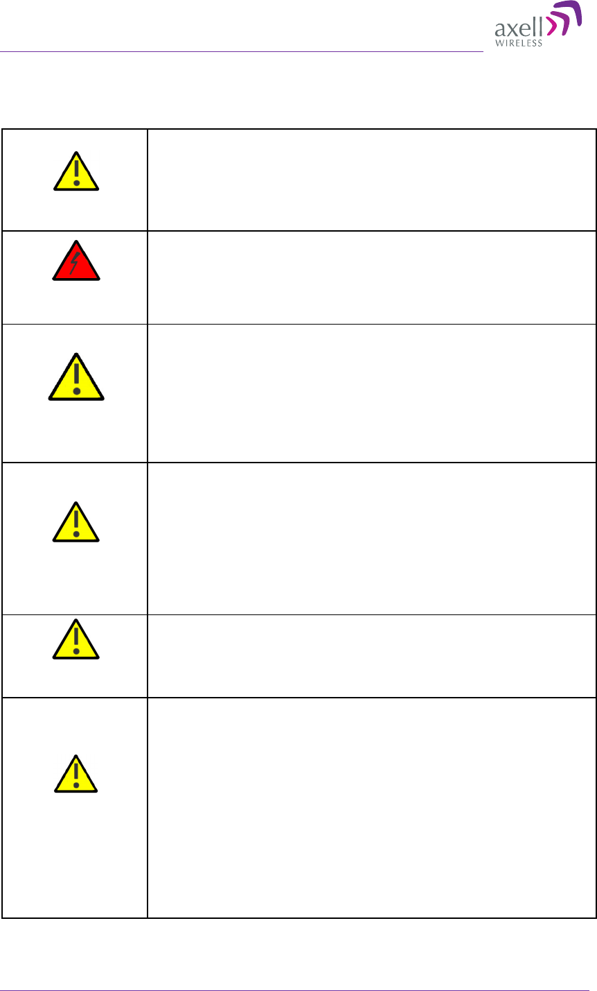
Caution labels!
Throughout this manual, there are "Caution" warnings. "Caution"
calls attention to a procedure or practice, which, if ignored, may
result in injury or damage to the system, system component or
even the user. Do not perform any procedure preceded by a
"Caution" until the described conditions are fully understood and
met.
Danger: Electrical
Shock
This equipment must be installed indoors only. . To prevent
electrical shock when installing or modifying the system power
wiring, disconnect the wiring at the power source before working
with un insulated wires or terminals.
Caution: Safety to
personnel
Before installing or replacing any of the equipment, the entire
manual should be read and understood.
The user needs to supply the appropriate AC or DC power to the
repeater. Incorrect power settings can damage the repeater and
may cause injury to the user.
Please be aware that the equipment may, during certain
conditions become very warm and can cause minor injuries if
handled without any protection, such as gloves.
Caution: Safety to
equipment
When installing, replacing or using this product, observe all
safety precautions during handling and operation. Failure to
comply with the following general safety precautions and with
specific precautions described elsewhere in this manual violates
the safety standards of the design, manufacture, and intended
use of this product.
Axell Wireless assumes no liability for the customer's failure to
comply with these precautions. This entire manual should be read
and understood before operating or maintaining the repeater.
Warning: Restricted
Access Location
Access to the Axell unit installation location is restricted to
SERVICE PERSONNEL and to USERS who have been instructed on
the restrictions and the required precautions to be taken.
Attention:
Electrostatic
Sensitivity
Observe electrostatic precautionary procedures.
ESD = Electrostatic Discharge Sensitive Device.
Semiconductor transmitters and receivers provide highly reliable
performance when operated in conformity with their intended
design. However, a semiconductor may be damaged by an
electrostatic discharge inadvertently imposed by careless
handling.
Static electricity can be conducted to the semiconductor chip
from the centre pin of the RF input connector, and through the
AC connector pins. When unpacking and otherwise handling the
repeater, follow ESD precautionary procedures including use of
grounded wrist straps, grounded workbench surfaces, and
grounded floor mats.

AXELL D-MBR 3007-3008-PS NFPA REPEATER
PRODUCT DESCRIPTION AND USER’S MANUAL
IX UMCD00013 Rev 2.2 © Axell Wireless Ltd
Table of Contents
1 Introduction .................................................................................................................................. 1
1.1 Main Features ........................................................................................................................ 2
1.2 Repeater Model ...................................................................................................................... 3
1.3 NFPA Installation Architecture ............................................................................................... 3
1.4 Smart-ALC Function ............................................................................................................... 4
1.5 Interfaces ................................................................................................................................ 4
1.6 Navigating the Web GUI Application ...................................................................................... 5
1.6.1 Topology Tree Branches ........................................................................................... 5
1.6.2 Operation Buttons ..................................................................................................... 6
1.6.3 Band Pane and Tabs ................................................................................................. 6
1.6.4 CMU Pane and Tabs ................................................................................................. 7
2 Antenna Installation Requirements ........................................................................................... 8
2.1 Base (Donor) Antenna Requirements .................................................................................... 8
2.1.1 Required Antenna Information .................................................................................. 8
2.1.2 Donor Antenna Specifications ................................................................................... 8
2.1.3 Installation Criteria ..................................................................................................... 8
2.2 Service Antenna Requirements ............................................................................................. 9
2.2.1 Required Information ................................................................................................. 9
2.2.2 Indoor Antenna Installations ...................................................................................... 9
2.2.3 Outdoor Installations ............................................................................................... 10
3 Installing the Repeater .............................................................................................................. 13
3.1 Repeater Pre-Installation Requirements .............................................................................. 13
3.1.1 Safety Guidelines .................................................................................................... 13
3.1.2 Required BTS Information ....................................................................................... 13
3.1.3 Installation Location and Environment .................................................................... 13
3.1.4 RF Cable Installation Guidelines ............................................................................. 14
3.1.5 Grounding Wires Requirements .............................................................................. 14
3.2 Overview of the Installation Procedure ................................................................................ 14
3.3 Unpacking ............................................................................................................................ 15
3.4 Mounting the D-MBR ............................................................................................................ 16
3.4.1 Pre-Mounting Procedure ......................................................................................... 16
3.4.2 Installing the Mounting Bracket ............................................................................... 17
3.4.3 Preparing Power Supply Cables ............................................................................. 17
3.4.4 Mounting the Repeater ............................................................................................ 18
3.5 Grounding ............................................................................................................................. 20
3.6 Before Connecting Antennas or Powering On! .................................................................... 20
3.6.1 Verifying Isolation between Donor and Mobile Antennas ....................................... 20
3.6.2 Verifying the Link between the BTS and the Repeater ........................................... 21
3.7 Antenna Connections ........................................................................................................... 21
3.8 Powering Up the D-MBR ...................................................................................................... 22
3.8.1 Standard Power Connection ................................................................................... 22
3.8.2 D-MBR-PS NFPA Power Connection...................................................................... 23
3.9 Alarm Connections ............................................................................................................... 23
3.9.1 Alarm Connector Pinout .......................................................................................... 24
3.9.2 Load Restrictions ..................................................................................................... 24
3.9.3 Summary Alarms Trigger Criteria ............................................................................ 25
3.9.4 D-MBR-PS-NFPA Installation Alarm Connections .................................................. 25

AXELL D-MBR 3007-3008-PS NFPA
PRODUCT DESCRIPTION AND USER’S MANUAL
X UMCD00013 Rev 2.2 © Axell Wireless Ltd
4 Initial Setup and Commissioning ............................................................................................. 26
4.1 Open a Session to the Repeater .......................................................................................... 26
4.1.1 Connect the Repeater to the Computer .................................................................. 26
4.1.2 Configure the Computer Network Parameters ........................................................ 26
4.1.3 Login to the Repeater .............................................................................................. 29
4.2 Configuring RF Parameters and Channels .......................................................................... 30
4.2.1 Control Params Tab ................................................................................................ 30
4.3 Setting Date and Time.......................................................................................................... 34
4.4 Configuring the External Alarms .......................................................................................... 35
4.5 Setting the IP Address.......................................................................................................... 36
5 Administrative Operations ........................................................................................................ 37
5.1 User Management ................................................................................................................ 37
5.1.1 User Levels .............................................................................................................. 37
5.1.2 Viewing the List of Defined Users ........................................................................... 37
5.1.3 Adding Users ........................................................................................................... 38
5.1.4 Editing a User .......................................................................................................... 38
5.1.5 Deleting a User ........................................................................................................ 38
5.2 Repeater and Band Level Information ................................................................................. 39
5.2.1 Viewing Repeater Level Information ....................................................................... 39
5.2.2 Viewing Band Level Info .......................................................................................... 39
5.3 Configuration Files Backup/Restore ..................................................................................... 40
5.3.1 The Backup/Restore Tab ........................................................................................ 41
5.3.2 Backup of Repeater Configuration .......................................................................... 42
5.3.3 Restoring Previous Repeater Configuration ............................................................ 42
5.3.4 Uploading New Configuration File to Repeater ....................................................... 43
5.3.5 Saving Configuration File to Computer ................................................................... 43
5.4 CMU Software Upgrade ....................................................................................................... 44
6 Monitoring and Troubleshooting.............................................................................................. 47
6.1 Front Panel LED ................................................................................................................... 47
6.2 GUI Alarm Descriptions ........................................................................................................ 48
6.3 Alarms Log ........................................................................................................................... 50
Appendix A: Specifications .......................................................................................................... 51
AXELL D-MBR 3007-3008-PS NFPA REPEATER
PRODUCT DESCRIPTION AND USER’S MANUAL
© Axell Wireless Ltd UMCD00013 Rev 2.2 1
1 Introduction
D-MBR 3007-3008 PS NFPA (Digital Multi Band Repeater for Public Safety) is a high-power
digital multi-channel signal booster (DCSB). It features an array of up to 12 DSP based,
software-controlled, variable bandwidth filters, that are user-programmable across the
700 and 800 MHz bands.
D-MBR 3007-3008 PS NFPA supports all public safety technologies. For each filter, the
user can specify the start and stop frequencies with different options varying in time delay
and filter slope. This allows the engineer to trade off adjacent channel rejection and time
delay interference against a wider coverage area, permitting D-MBR 3007-3008 PS NFPA
usage in applications where no other booster solution will work.
Every parameter of D-MBR 3007-3008 PS NFPA, including filter tuning and selection, can
be controlled via web based management. The patented Axell Wireless’ digital RF filter
enables simple initial setup for any channel plan and if necessary, allows some basic
reconfiguration due to re-banding.
SALC-Smart ALC mechanism to protect the digital signal booster from oscillation and
shutdown the signal booster when required.
With the NFPA option, this Axell product meets the rigid requirements as defined by the
NFPA and International Fire Code developmental organizations. The amplifier meets
NEMA4 compliance for hose-down and provides all Alarming outputs as defined by NFPA
2010, Chapter 24, including system and antenna failures.
Axell also offers the following options to meet additional code compliance needs:
• 12 or 24 hour compliant UPS back up – meets NEMA 4 and alarming requirements
• External Phone Dialer – meets NEMA 4 and allows Dial-out to paging devices when
an alarm is triggered
• Outer casing is painted Fire Life Safety Red
D-MBR 3007-3008 PS NFPA

AXELL D-MBR 3007-3008-PS NFPA REPEATER
PRODUCT DESCRIPTION AND USER’S MANUAL
2 UMCD00013 Rev 2.2 © Axell Wireless Ltd
1.1 Main Features
• Class A or B- signal booster ( based on filter setting) for SMR and public safety
networks
• Supports APCO 25 phase 1 and 2 for public safety networks
• NFPA 72-2010, Chapter 24 and IFC 510.1 Compliant
• Support of 700MHz D block for LTE network
• SMR 700MHz and 800MHz bands in a single enclosure
• RF Gain: Up to 85dB Gain
• SALC-Smart ALC mechanism to protect the digital signal booster from oscillation
and shutdown the signal booster when required
• Output Power per band: DL +30dBm; UL +24dBm
• Composite Output Power: DL +33dBm; UL +27dBm
• Web based management GUI, SNMP traps
• Patented DSP filtering™ technology
• Supports up to 12 independent filters; user programmable bandwidth /
frequency
• For SMR700: Programmable 12.5 kHz to 17MHz
• For SMR800: Programmable 12.5 kHz to 10MHz
• User-selectable adjacent channel rejection and time delay to minimize
interference
• IP65 (NEMA 4) Enclosure
Axell D-MBR 3007-3008-PS-NFPA
PRODUCT DESCRIPTION AND USER’S MANUAL
© Axell Wireless Ltd UMCD00013 Rev 2.2 3
1.2 Repeater Model
ORDERING INFORMATION
Identification Description Part Number
D-MBR 3007-3008
PS NFPA AC
Digital Multi Channel Selective Repeater
700/800 12 channels,
30 dBm output power per band, 85 dB
gain, AC powering with NFPA and IFC
compliant Alarm Outputs, Red colored
case
D-MBR 7/8 PS
30DBM 12 FIL NFPA
RED
D-MBR 3007-3008
PS NFPA DC
Digital Multi Channel Selective Repeater
700/800 12 channels,
30 dBm output power per band, 85 dB
gain, DC powering with NFPA and IFC
compliant Alarm Outputs, Red colored
case
D-MBR 7/8 PS
30DBM 12F NFPA DC
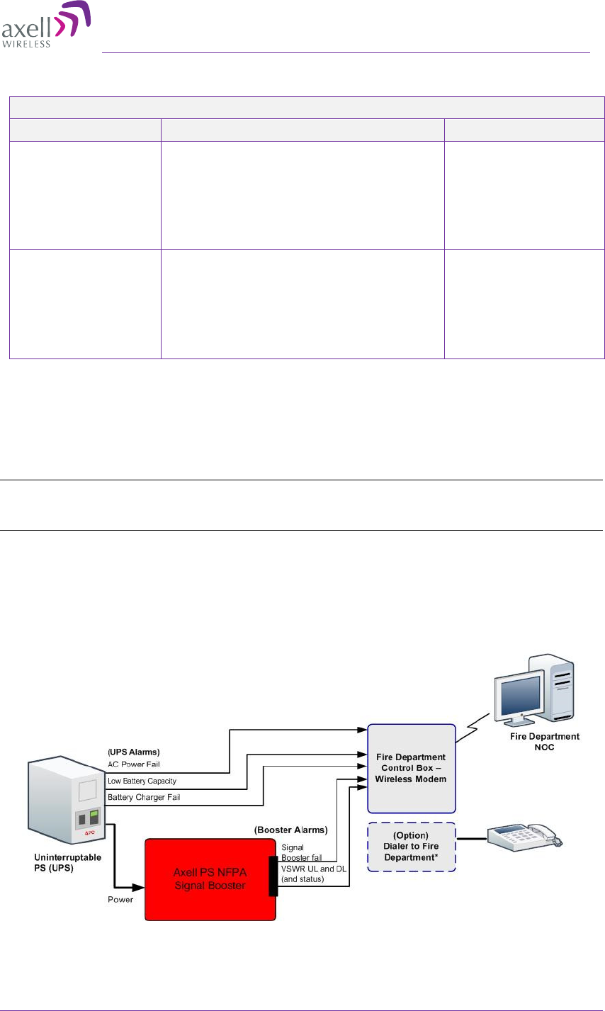
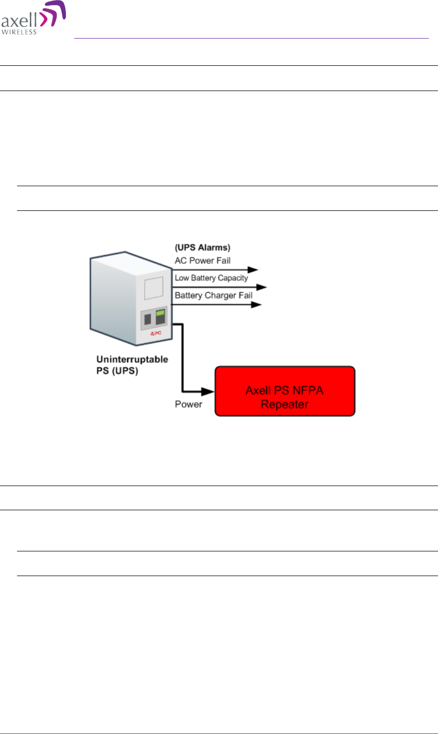
1.3 NFPA Installation Architecture
To meet the National Fire Protection Association (NFPA) requirements, power to the
Repeater is provided via a UPS and the status of the UPS, Repeater and DAS system
(antennas) is monitored via alarm connections to the Fire Department Control Box.
NOTE: An alternative to the Fire Department Control Box connections is to connect the D-MBR PS
NFPA and UPS dry contact alarms to an Automatic Dialer. Axell Wireless recommends the AD-2000
Automatic Voice/Pager Dialer System.
The alarms are connected as follows:
• From the UPS - the power indicator alarms are connected directly to the Fire
Department Control Box.
• From the Repeater – the Repeater status and antenna status alarms are connected
to the Control Box
Figure 1-1. D-MBR PS NFPA Architecture
AXELL D-MBR 3007-3008-PS NFPA REPEATER
PRODUCT DESCRIPTION AND USER’S MANUAL
4 UMCD00013 Rev 2.2 © Axell Wireless Ltd
1.4 Smart-ALC Function
The Repeater’s power amplifier includes power-monitoring circuits with Automatic Level
Control (ALC) that prevents excessive output power while maintaining the power amplifier
linearity
The Smart Automatic Level Control (Smart-ALC) is an innovative algorithm for automatic
Repeater gain adjustment. Combined with advanced control algorithms, S-ALC is capable
of learning the traffic load characteristics and adjusting the Repeater RF Gain to the
desired value. Smart-ALC effectively reduces isolation problems.
NOTE: To reset the Repeater to its highest set gain value, disconnect the Repeater power cable for
several seconds and re-connect.
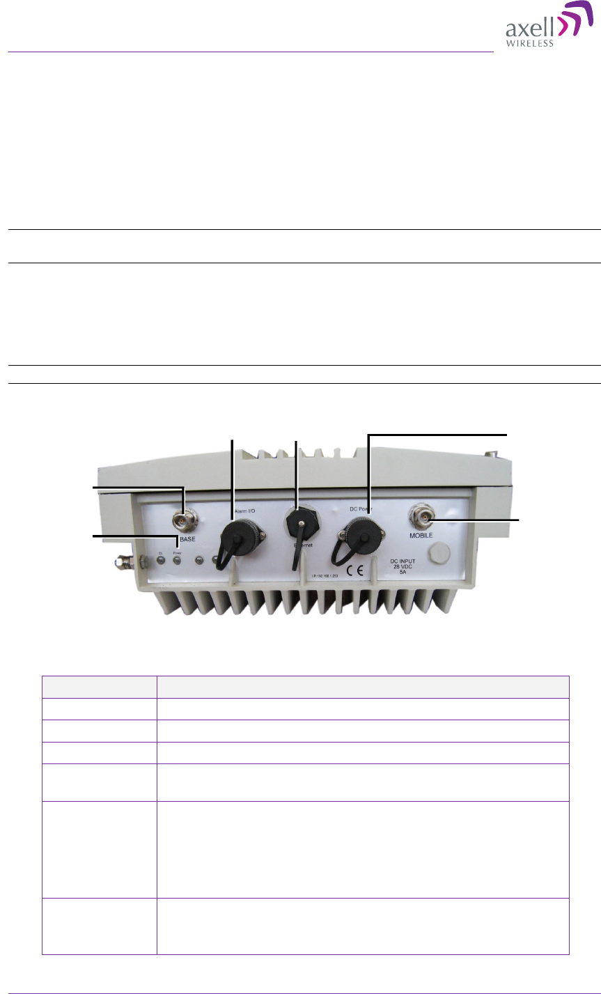
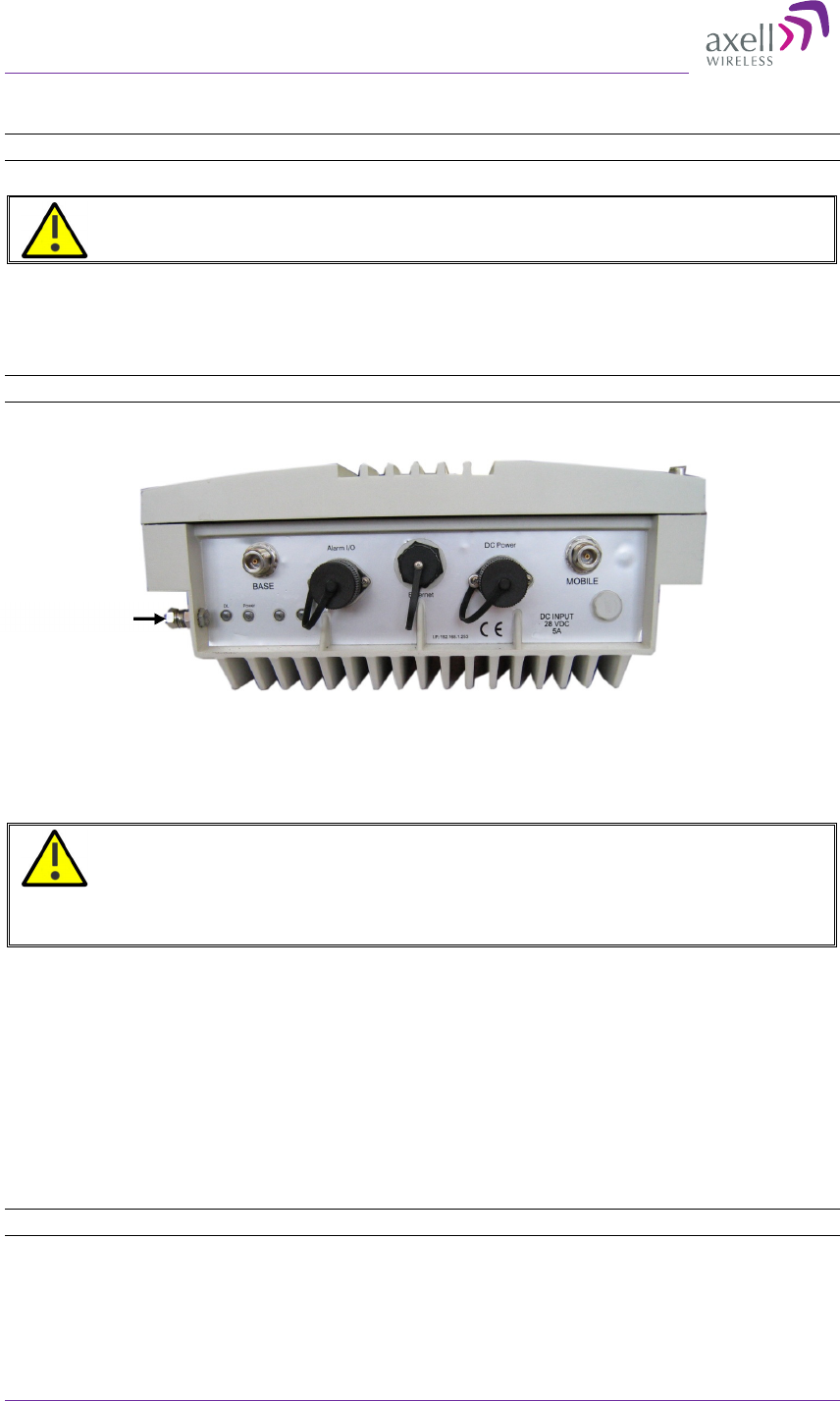
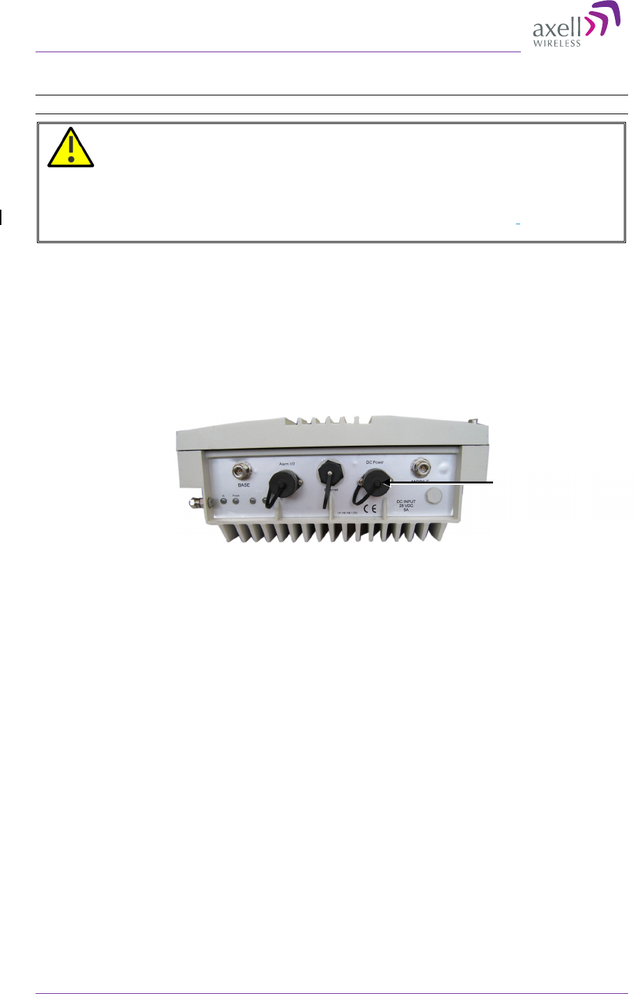
1.5 Interfaces
All the Repeater interfaces are located on the units’ underside panel. The following figure
shows the interfaces on the D-MBR.
NOTE: The NFPA unit is colored RED.
1-2. Axell D-MBR 3007-3008-PS NFPA Front Panel Interfaces
The following table provides a description of the front panel ports and connections.
Interface Description
Base Connection to Base (donor) side antenna
Mobile Connection to mobile (service) side antenna
Ethernet Connection to Ethernet devices.
Dry contact
NFPA alarms
See section 3.9 for description of alarm connections.
DC Power Model dependant:
• Power from system AC to DC converter mounted on the
wall mount bracket. Do not connect directly to any other
power supply!!!
• Power from system DC source.
LED - Steady Green – Normal operation
- Red or Orange - see section 6.1Error! Reference source
not found.
Service
antenna
connections
DC Power
Donor antenna
connections
DL
and
Power LEDs
Ethernet
Dry contact
NFPA alarms
Axell D-MBR 3007-3008-PS-NFPA
PRODUCT DESCRIPTION AND USER’S MANUAL
© Axell Wireless Ltd UMCD00013 Rev 2.2 5
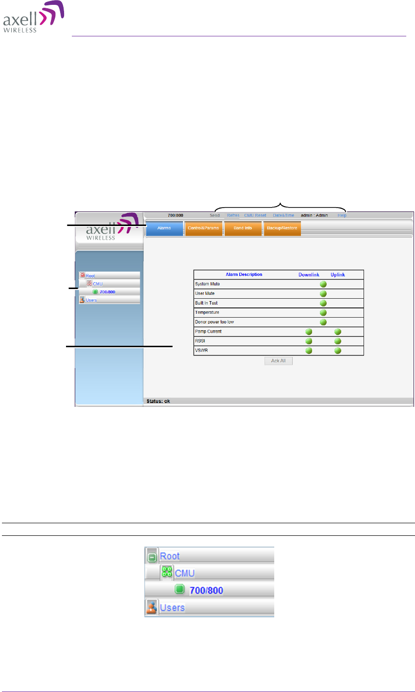
1.6 Navigating the Web GUI Application
This section describes how to navigate the Web Management application. The Web Access
interface provides the following groups of options:
• Topology Tree – provides access to unit level and band level options
• Tabs – Band and unit (CMU) level options corresponding to the selected tree item
• Operation buttons – control and management options
The operation buttons at the top are common to all tree items and menus.
Figure 1-3. Web GUI Overview
1.6.1 Topology Tree Branches
The Topology Tree displays:
• CMU – Communication parameters
• 700/800 - Repeater configuration and monitoring options
• Users - User management options
NOTE: The items in the Tree Pane display the color of the most severe alarm.
Figure 1-4. Topology Tree
Tree
Pane related to
selected
tab
Tabs related to
selected
Tree
item
Operation buttons
AXELL D-MBR 3007-3008-PS NFPA REPEATER
PRODUCT DESCRIPTION AND USER’S MANUAL
6 UMCD00013 Rev 2.2 © Axell Wireless Ltd
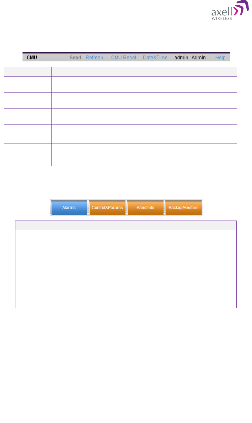
1.6.2 Operation Buttons
The following Operation buttons are available.
Item Description / Values
Send Click to save changes – before exiting the screen; otherwise,
changes will not be saved.
Refresh Click to refresh the current screen and update the displayed
data
CMU Reset Click to reset the Web Access application. Use in case of failure
or display problems
Date and Time
Used to set the Repeater clock.
Admin: Admin Shows the current access level.
Help Click Help to display an e-guide line for the system operation.
This Help is general by its nature and some features may not
be included.
1.6.3 Band Pane and Tabs
The upper area of each selected pane shows the tabs corresponding to that pane.
Item Description / Values
Alarms Displays various alarms generated by the Repeater and
enables monitoring. See section 6.2.
Control and
Params
Used for adjusting RF parameters and channel
configuration (signal level, gain and bandwidth). See
section 4.2.
Band Info Shows information on the current band. See
section 5.2.2
Backup and
Restore
Configuration files management options (configuration
files can be stored on the Repeater for access). See
section 5.3.
Axell D-MBR 3007-3008-PS-NFPA
PRODUCT DESCRIPTION AND USER’S MANUAL
© Axell Wireless Ltd UMCD00013 Rev 2.2 7
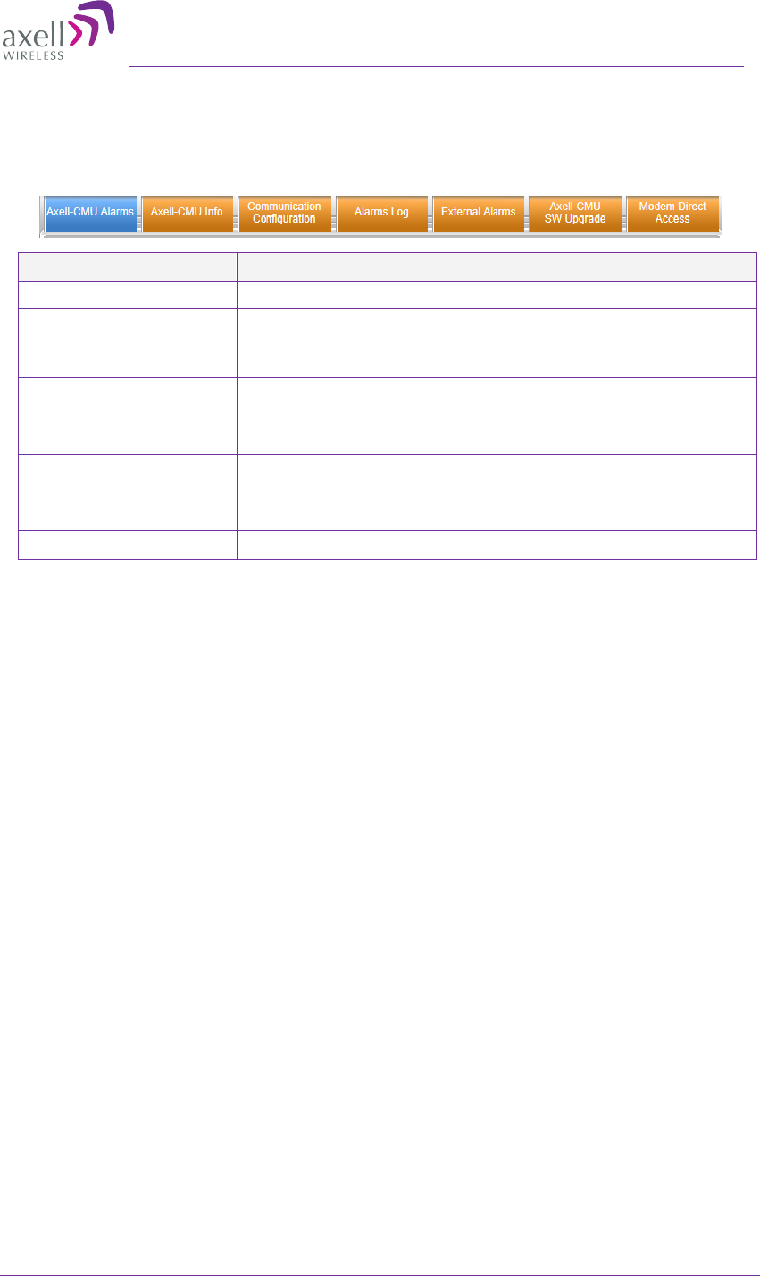
1.6.4 CMU Pane and Tabs
CMU Topology Tree menu items.
Item Description / Values
Axell-CMU Alarms Shows any generated external alarms .
Axell CMU Info Shows Repeater level information such as SW and HW
versions and identification number. In addition, enables
setting minimum alarm levels. See section 5.2.1
Communication
Configuration
Used to set communication parameters. See section 4.5.
Alarms Log Log of past and current alarms. See section 6.3
External Alarms Used to define any connected external alarms. See
section 4.4.
Axell-CMU SW Upgrade Options for CMU software upgrade. See section 5.4.
Modem Direct Access N/A

AXELL D-MBR 3007-3008-PS NFPA REPEATER
PRODUCT DESCRIPTION AND USER’S MANUAL
8 UMCD00013 Rev 2.2 © Axell Wireless Ltd
2 Antenna Installation Requirements
This chapter provides information on the specifications of the donor and service antennas
suitable for operation with this repeater, on the installation requirements of the antennas
and on the Repeater installation site and cable requirements.
ATTENTION!!
The BSR-3308 models described in this manual have been approved by Industry Canada
to operate with the antenna types listed below with the maximum permissible gain and
required antenna impedance for each antenna type indicated. Antenna types not included
in this list, having a gain greater than the maximum gain indicated for that type, are
strictly prohibited for use with this device.
Le présent émetteur radio (identifier le dispositif par son numéro de certification ou son
numéro de modèle s'il fait partie du matériel de catégorie I) a été approuvé par Industrie
Canada pour fonctionner avec les types d'antenne énumérés ci-dessous et ayant un gain
admissible maximal et l'impédance requise pour chaque type d'antenne. Les types
d'antenne non inclus dans cette liste, ou dont le gain est supérieur au gain maximal
indiqué, sont strictement interdits pour l'exploitation de l'émetteur.
2.1 Base (Donor) Antenna Requirements
The Base (Donor) antenna is usually installed outdoors and is either a directional antenna
such as a Yagi or a Panel antenna.
2.1.1 Required Antenna Information
You will require the following antenna information
•
Antenna type and characteristics
•
Height
•
Length and type of coaxial cable required for connecting the Donor antenna to the
Repeater and the attenuation.
2.1.2 Donor Antenna Specifications
•
Max DONOR antenna gain (dBi) = 37 – (27dbi - cable losses in dbi).
•
Very sharp beam pointed to the BTS.
•
Minimum cable and jumper loss = 2dB.
2.1.3 Installation Criteria
Installation requirements:
•
Verify the Donor antenna location provides a line-of-sight to the Base Station and
maximum input power.
•
Install the Donor Antenna at the designated height.
•
Install the donor antenna at a higher level (i.e. floor) than the mobile antenna.
•
Must be installed at a minimum distance of 30 cm for indoor applications from any
personnel within the area.

Axell D-MBR 3007-3008-PS-NFPA
PRODUCT DESCRIPTION AND USER’S MANUAL
© Axell Wireless Ltd UMCD00013 Rev 2.2 9
2.2 Service Antenna Requirements
The Service antenna type depends on whether the Repeater is installed indoors or outdoors.
WARNINGS!!!
•
The installer is held accountable for implementing the rules required
for deployment.
•
Good engineering practice must be used to avoid interference.
•
Output power should be reduced to solve any IMD interference issues.
2.2.1 Required Information
The following antenna requirements, specifications and site considerations should be met:
•
Type of installation – indoor only
•
Service area type and size and characteristics
•
Height
•
Length and type of coaxial cable required for connecting the antenna to the Repeater
and the attenuation.
2.2.2 Indoor Antenna Installations
2.2.2.1 Recommended Antennas
The following describes the requirements for an omni-directional mobile used for indoor
applications.
Specifications:
•
One or a combination of the following antennas can be used: Ceiling Mount Patch
antenna, Wall Mount Patch antenna, Corner Reflector.
•
Choose an antenna with high side lobe attenuation which enables maximum
isolation.
•
Maximum antenna gain for indoor operation 2.2dBi.
•
Cable and jumper loss is at least 2dB.
•
[Gain Antenna – Cable loss] should not exceed 0.2 dB

AXELL D-MBR 3007-3008-PS NFPA REPEATER
PRODUCT DESCRIPTION AND USER’S MANUAL
10 UMCD00013 Rev 2.2 © Axell Wireless Ltd
2.2.2.2 Installation Criteria
Installation requirements:
•
An indoor antenna should be installed at a convenient location. It should be free of
metallic obstruction.
•
Install the Service Antenna at the designated height and tune it roughly toward the
Service coverage area.
•
Installation of this antenna must provide a minimum separation distance of 22cm
from any personnel within the area.
2.2.3 Outdoor Installations
For applications in which the Mobile antenna is installed outdoor, the antenna type is
chosen according to the available infrastructure (single-pole or horizontal installation). In
addition, isolation between the donor and service antennas must be taken into account
when selecting the location of the antennas.
2.2.3.1 Recommended Antennas
The antenna type depends on the installation:
•
For vertical Single Pole installations a high side lobe suppression antenna is
required.
•
For horizontal installations either on two separate poles or on two sides of one
building a high front to back ratio antenna is required.
Specifications:
•
Maximum antenna gain for outdoor operation 8dBi.
•
Cable and jumper loss is at least 2dB.
•
[Gain Antenna – Cable loss] should not exceed 6dB
Installation requirements:
•
Installation of this antenna must provide a minimum separation distance of 44 cm
from any personnel within the area.
NOTE: The Single Pole (Vertical) and Horizontal Installations are described in sections 2.2.3.2 and
2.2.3.3.
Axell D-MBR 3007-3008-PS-NFPA
PRODUCT DESCRIPTION AND USER’S MANUAL
© Axell Wireless Ltd UMCD00013 Rev 2.2 11
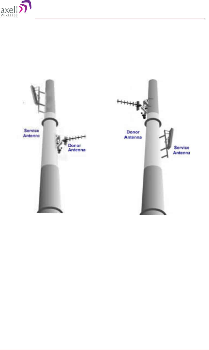
2.2.3.2 Vertical Separation Configuration
The Vertical Separation configuration is recommended in cases where the BTS is relatively
far and the service coverage area is relatively small.
In Vertical Separation configuration, the Donor antenna can be installed either above or
below the Service antenna on a COMMON tower. It is required to set the distance between
them to achieve maximum isolation.
The figures below illustrate the installations.
Figure 2-1. Service above Donor Antenna Figure 2-2. Donor above Service Antenna
AXELL D-MBR 3007-3008-PS NFPA REPEATER
PRODUCT DESCRIPTION AND USER’S MANUAL
12 UMCD00013 Rev 2.2 © Axell Wireless Ltd
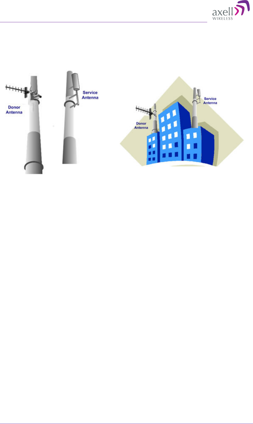
2.2.3.3 Horizontal Separation Configuration
In the Horizontal Separation configuration, the Donor and Service antennas are installed
on two separate towers at approximately the same height. The towers can be either on
the same side of the building or on different sides of the building as shown below.
Figure 2-3. Donor and Service Antennas
Installed on Separate Towers
Figure 2-4. Service and Donor Antennas Installed
on Opposite Sides of the Building
Axell D-MBR 3007-3008-PS-NFPA
PRODUCT DESCRIPTION AND USER’S MANUAL
© Axell Wireless Ltd UMCD00013 Rev 2.2 13
3 Installing the Repeater
3.1 Repeater Pre-Installation Requirements
3.1.1 Safety Guidelines
Before installing the Repeater, review the following safety information:
•
Follow all local safety regulations when installing the Repeater.
•
Only qualified personnel are authorized to install and maintain the Repeater.
•
Ground the Repeater with the grounding bolt located on the external lower side of
the Repeater).
•
Do not use the grounding bolt to connect external devices.
•
Follow Electro-Static Discharge (ESD) precautions.
•
Use low loss cables to connect the antennas to the Repeater.
3.1.2 Required BTS Information
Required BTS Information
•
BTS channels
•
BTS output power per channel
•
BTS antenna gain
•
BTS antenna height
•
Distance from Repeater site to BTS
3.1.3 Installation Location and Environment
WARNINGS!!!
the Repeater must always be installed vertically and top-down – with the
connectors on the underside for protection .
Horizontal installation on a bench for long time may cause damage to the
Repeater due to over-heating.
The following criteria should be considered when selecting the Repeater installation site
location:
•
Application type – indoor or outdoor
•
Distance from antenna site - It is recommended that the installation location be as
close as possible to the antenna site in order to maintain the cable loss to a
minimum.
•
General surroundings and accessibility of location
•
In outdoor applications it is recommended to install a cabinet or a shielding sunroof
for further protection against weather wear.
•
Use a suitable mounting surface, such as a flat back rigid wall.
•
The Repeater is convection cooled so airflow and alternation should be possible.
•
Install the Repeater in a shielded, ventilated, and easy-to-reach area – preferably at
eye level.
•
Ensure that adequate airflow and ventilation within the rack and around the installed
components so that the safety of the equipment is not compromised.

AXELL D-MBR 3007-3008-PS NFPA REPEATER
PRODUCT DESCRIPTION AND USER’S MANUAL
14 UMCD00013 Rev 2.2 © Axell Wireless Ltd
•
Verify that there is a minimum of a 50 cm (20”) radius of space around the Repeater
and 1 meter in depth (3 ft) in order to allow the unit door to swing completely open,
enabling easy access to the Repeater for maintenance and on-site inspection.
•
Follow Electro-Static Discharge (ESD) precautions.
•
Install the Repeater close to the service area to monitor the output power and noise
figure.
•
Verify that ambient temperature of the environment does not exceed 50°C (122°F)
3.1.4 RF Cable Installation Guidelines
• For all coaxial connections to/from the Repeater - high performance, flexible, low
loss 50Ω coaxial communications cable.
•
All cables shall be weather-resistant type.
•
Cable length - determined by the Repeater installation plan. When calculating the
cable length, take into account excess cable slack so as not to limit the insertion
paths.
3.1.5 Grounding Wires Requirements
Requirements for grounding wires
•
Protective grounding conductor - should be aluminum with cross-section 10AWG.
•
Lug of the protective grounding conductor - should be aluminum
•
Washers and screw - should be high Cr stainless steel, or 12% Cr stainless steel, or
Cr on, Ni on steel, tin on steel
3.2 Overview of the Installation Procedure
IMPORTANT:
Be sure to perform the power supply connection last, otherwise damage may be
caused to the system!
1. Select the location for the system according to the requirements described in
section 3.1.3 and unpack the Repeater kit.
2. Mount the D-MBR-PS-NFPA Repeater on a (concrete or brick) wall (see 3.4).
3. Ground the Repeater (see 3.5)
4. If not yet installed, position and install the Base and Mobile antennas in the relevant
locations at the site.
5. Before connecting the antennas to the Repeater:
•
Test isolation between the Base and Donor antennas.
•
Verify link between BTS and Base Repeater.
6. Connect the Donor antenna to the Repeater (see 3.7).
7. Connect the power via the UPS (see 3.8).
8. Connect the Alarms from the:
•
Repeater – see 3.9.1 for pinout
•
UPS
9. Commission the system. See Chapter 4 - Initial Setup and Commissioning.
Note: It is important to perform the installation procedure according to the order previously described.
A standard professional toolbox is required in order to mount the Repeater.
Axell D-MBR 3007-3008-PS-NFPA
PRODUCT DESCRIPTION AND USER’S MANUAL
© Axell Wireless Ltd UMCD00013 Rev 2.2 15
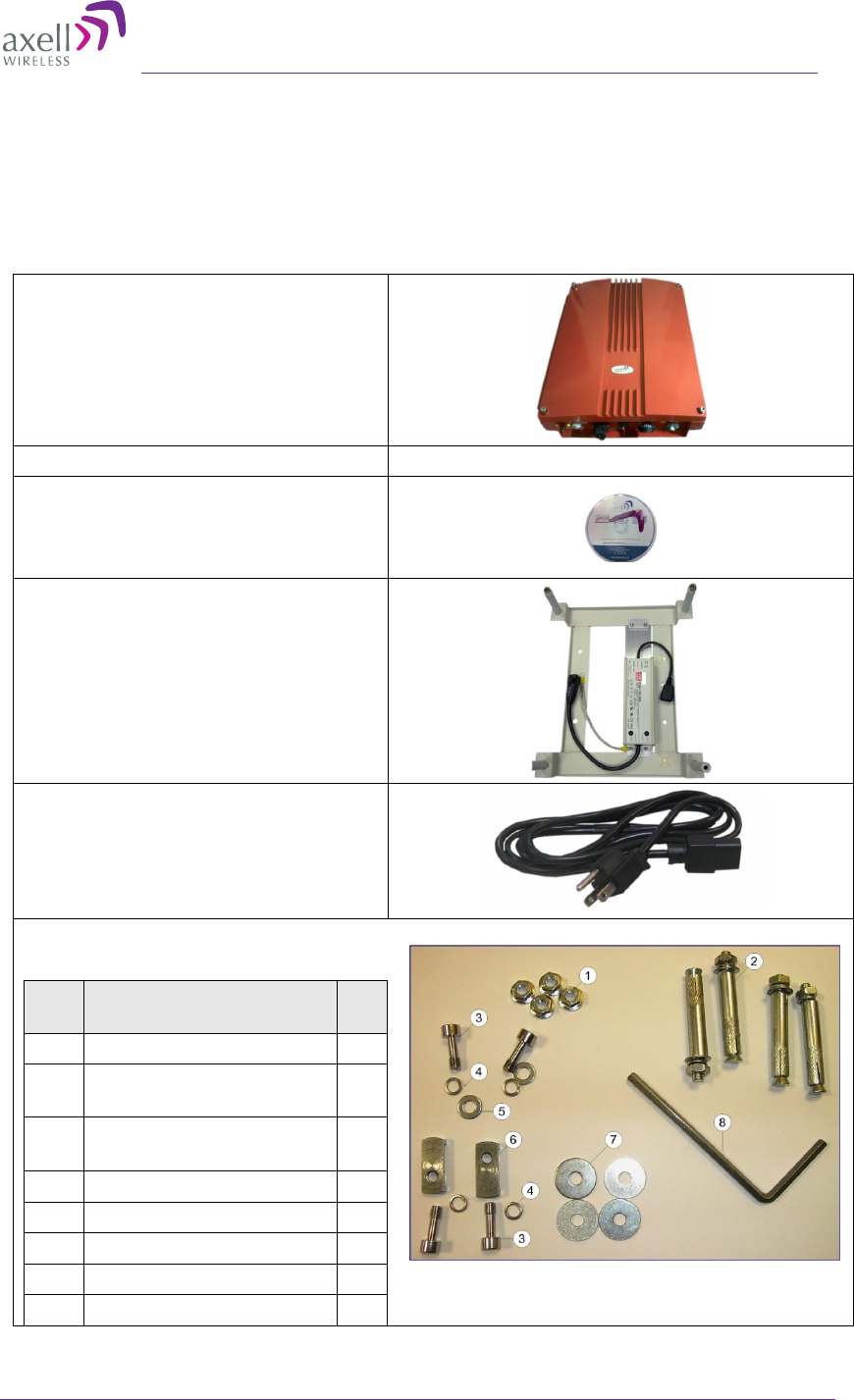
3.3 Unpacking
Upon receiving the D-MBR unit, perform the following:
• Examine the shipping container for damage before unpacking the unit.
• Perform a visual inspection to reveal any physical damage to the equipment.
• Verify that all of the equipment (listed below) is included (see also the following
page). Otherwise contact Axell Wireless.
D-MBR PS-NFPA
Ethernet cable
CD with documentations
Mounting Bracket with AC to DC
power converter.
US power plug cables (to AC outlet)
Additional (supplied) installation
components:
No. Description No
.
1 Flange nut, 5/16 4
2 Wedge anchor, ∅ 12 x
65 mm
4
3 Hex washer head screw,
∅ 8 mm
4
4 Washer, spring, ∅ 8 mm 4
5 Washer, flat, ∅ 8 mm 2
6 Clamp 2
7 Washer, flat, ∅ 28 mm 4
8 Screwdriver, Allen 1
Figure 3-1. Installation Components
AXELL D-MBR 3007-3008-PS NFPA REPEATER
PRODUCT DESCRIPTION AND USER’S MANUAL
16 UMCD00013 Rev 2.2 © Axell Wireless Ltd
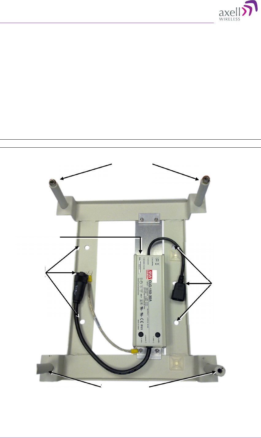
3.4 Mounting the D-MBR
3.4.1 Pre-Mounting Procedure
1. Choose the location of the Repeater on the wall according to the following criteria:
• The location should be at normal eye level height, above ground.
• Be sure to allow easy access to the Repeater for maintenance and on-site
inspection.
2. Place the Mounting Bracket against the wall and mark the four holes to be drilled at
the extreme four corners of the bracket (additional optional installation holes are
also provided).
3. Drill four holes 12mm in diameter and 65mm in depth.
The following illustration shows the bracket with the bracket pins.
NOTE: The NFPA bracket may be colored RED.
Figure 3-2. D-MBR 3007-3008-PS-NFPA Mounting Holes and Pins
Optional
installation holes
Optional
installation holes
2x bottom holes
2x top holes
Assembled PS
Axell D-MBR 3007-3008-PS-NFPA
PRODUCT DESCRIPTION AND USER’S MANUAL
© Axell Wireless Ltd UMCD00013 Rev 2.2 17
3.4.2 Installing the Mounting Bracket
To install the mounting bracket
1. Insert the four wedge anchors (see item no. 2 in Figure 3-1) into the drilled holes
and secure them with an adjustable wrench.
2. Remove the hex nut, spring washer and flat washer from each wedge anchor,
revealing a screw from each anchor.
3. Insert a flat washer 28mm in diameter in each of the anchors (see item 7 in
Figure 3-1).
4. Fit the support bracket on to the anchors and secure with the flat washers, spring
washers and hex nuts removed in Step 2.
5. Verify that the bracket is firmly mounted.
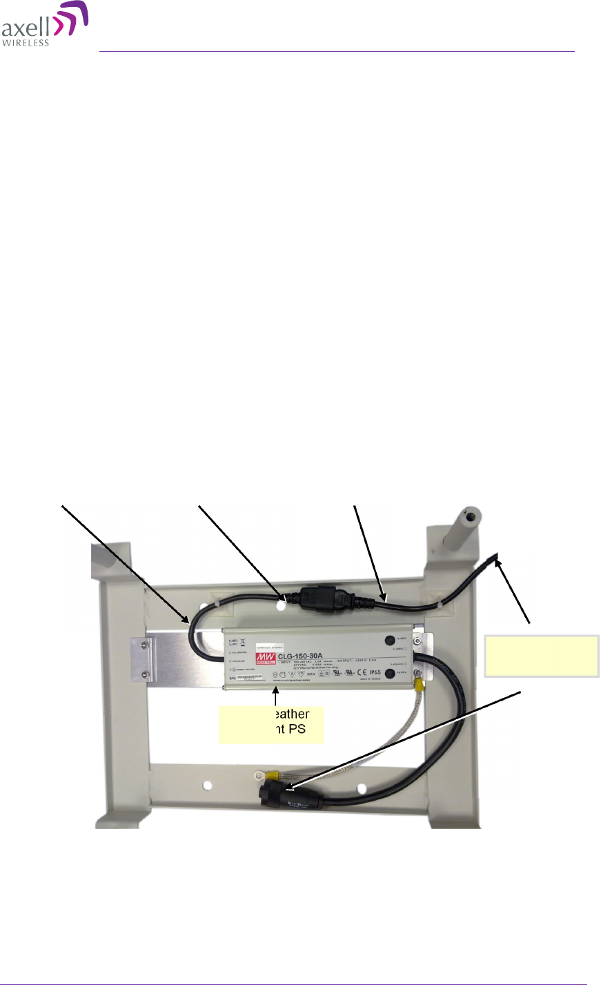
3.4.3 Preparing Power Supply Cables
1. Secure the AC/DC Converter power cable (with kettle socket) to the mounting
bracket using one of the supplied cable ties.
2. Connect the provided AC plug cable (EURO/UK) to the power supply kettle socket,
routing it to the bottom of the bracket, and secure with supplied cable tie.
3. DO NOT connect the AC or DC power cables at this stage – wait until instructed to do
so.
Figure 3-3. D-MBR 3007-3008-PS-NFPA Cables
DO NOT connect
at this time
IP65 weather
resistant PS
Cable secured with
cable tie
AC plug cable
secured with cable
tie
Connected kettle socket
cable and AC plug cable
AXELL D-MBR 3007-3008-PS NFPA REPEATER
PRODUCT DESCRIPTION AND USER’S MANUAL
18 UMCD00013 Rev 2.2 © Axell Wireless Ltd
3.4.4 Mounting the Repeater
1. Pick up the Repeater and align the Repeaters’ four installation holes with the
Mounting Brackets’ pins.
2. Slide the brackets pins through the Repeater holes until the upper side is locked with
the installation head nuts at the top of the bracket. See Figure 3-5.
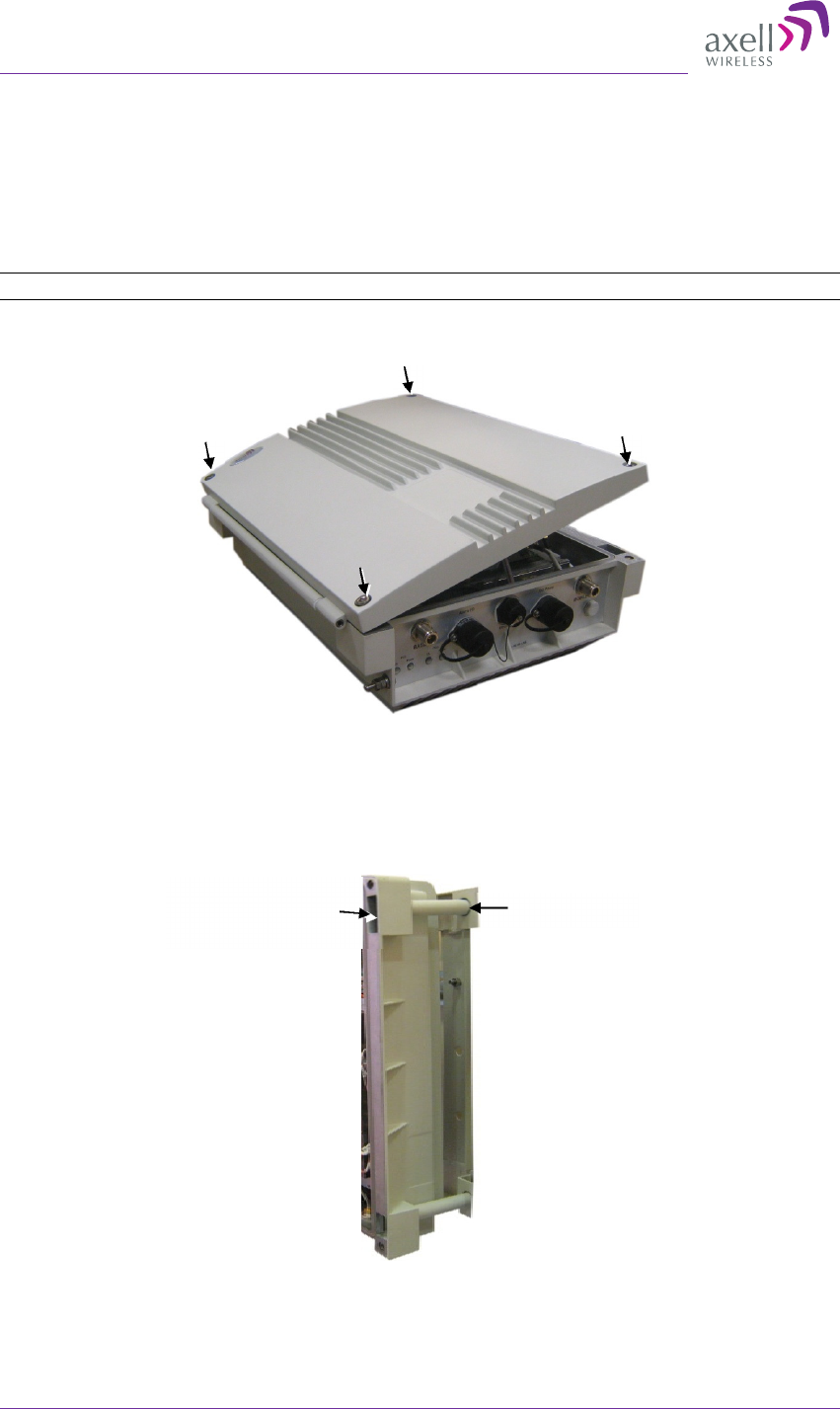
3. Release the four captive screws locking the Repeater cover.
NOTE: The NFPA unit is colored RED.
Figure 3-4. Loosen Captive Screws and Swing Open Door
4. Swing the top cover open.
Figure 3-5.D-MBR 3007-3008-PS-NFPA Mounted on Support Bracket
5. Set both clamps with a hex washer head screw (item 3 in Figure 3-1).
Bracket pin
Repeater
installation hole
Axell D-MBR 3007-3008-PS-NFPA
PRODUCT DESCRIPTION AND USER’S MANUAL
© Axell Wireless Ltd UMCD00013 Rev 2.2 19
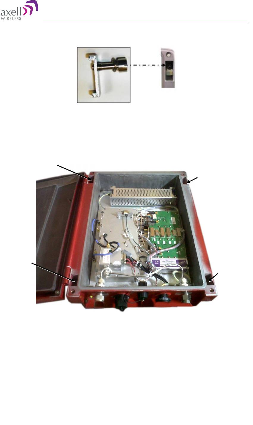
6. Insert the clamps including the screws in to the upper orifices leading inside the
Repeater.
Figure 3-6. Locking Clamp
7. Using the Allen screwdriver (item 8 in Figure 3-1), tighten the hex screw of the
clamp.
8. Insert two hex washer head screws (item 3 in Figure 3-1) including spring washers
(item 4 in Figure 3-1) into the lower orifices of leading inside the Repeater.
Figure 3-7. Locking Clamp Locations
9. Use the Allen screwdriver (8 in Figure 3-1) to tighten the hex screws.
10. Verify that the Repeater is firmly mounted.
11. Close the Repeater cover. Do not lock yet since you will need to open it to perform
the Local setup procedure.
Upper orifice
Lower orifice
Lower
orifice
Upper orifice
AXELL D-MBR 3007-3008-PS NFPA REPEATER
PRODUCT DESCRIPTION AND USER’S MANUAL
20 UMCD00013 Rev 2.2 © Axell Wireless Ltd
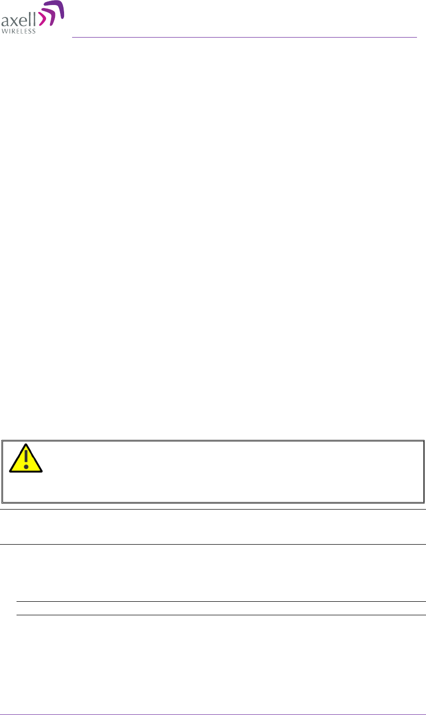
3.5 Grounding
NOTE: Refer to section 3.1.5 for the grounding requirements.
WARNINGS!!! Do not use the grounding bolt to connect external devices.
To ground repeater
Connect main ground to Repeater grounding lug at the side of the repeater.
NOTE: The NFPA unit is colored RED.
Figure 3-8. Grounding Lug Location
3.6 Before Connecting Antennas or Powering On!
WARNING!
Perform this procedure before connecting the antennas to the Repeater or
powering on the Repeater.
The Repeater should not be operated prior to the verification of the operating
parameter in its installation environment
3.6.1 Verifying Isolation between Donor and Mobile Antennas
The isolation between the Base/Donor and Mobile/Service antennas is critical especially
for high gain, outdoor applications.
• For proper operation of the Repeater, it is recommended that the isolation between
the Donor and Service antennas be at least 16dB higher than the Repeaters set gain.
• Insure proper vertical or horizontal distance separation between Donor and Service
antennas
NOTE: Lower isolation can lead to high in-band ripple, oscillations and low signal quality.
Grounding lug
Axell D-MBR 3007-3008-PS-NFPA
PRODUCT DESCRIPTION AND USER’S MANUAL
© Axell Wireless Ltd UMCD00013 Rev 2.2 21
To measure the isolation, proceed as follows:
1. Inject a known signal from a signal generator into one antenna (preferably the
Donor antenna).
2. Measure the coupled output from the Service antenna, using the Spectrum analyzer
and LNA if applicable.
3. Perform this procedure across the frequency range of both the Uplink and Downlink
bands.
4. Register the lower result for system operation.
3.6.2 Verifying the Link between the BTS and the Repeater
This test checks the signal strength from the BTS antenna to the Repeater.
Proceed as follows:
1. Using a Spectrum analyzer, measure the received signal from BTS at the Donor
antenna port near the Repeater.
2. Adjust the Donor antenna direction to receive the maximum signal strength.
3. Compare the received signal strength with the calculated signal strength from the
design phase.
•
In case of discrepancy, check for one of the following:
o
Antenna out of direction
o
Antenna tuned to side lobe instead of main lobe
o
Antenna connector or antenna cable faulty
o
Line-of-sight problem (obstruction), etc.
•
Register the signal strength of the downlink channel. for the system operation
phase.
3.7 Antenna Connections
WARNING!
Do not connect the antenna cables to the Repeater before verifying the installation
parameters - specifically the isolation between the antennas.
DO NOT POWER-ON the Repeater without either the antennas being connected
or the antenna connections terminated with dummy loads
NOTE: If the coaxial cables are NOT weather-resistant type, wrap the exterior coaxial cables with
insulation and holding tape (Type 3M Rubber splicing tape) for environmental protection and to
ensure longer lifetime.
To connect the antennas to the Repeater
1. Install the antenna cables along their path to the Repeater, and connect them to the
Antennas.
Note: Be sure to use low loss cables.
2. Connect the Donor antenna to the Repeater BASE port. (Donor antenna
specifications and installation criteria are described in section 2.1.
3. Connect the Service Antenna to the Repeater MOBILE port. (Mobile antenna
specifications and installation criteria are described in section 2.2).
4. Verify all RF connectors are tightened and the cables and antennas are secured.
AXELL D-MBR 3007-3008-PS NFPA REPEATER
PRODUCT DESCRIPTION AND USER’S MANUAL
22 UMCD00013 Rev 2.2 © Axell Wireless Ltd
3.8 Powering Up the D-MBR
NOTE: The Repeater is connected to power via the assembled AC/DC power supply.
WARNING!
This equipment can either be installed indoors or outdoors.
When installing outdoors - Wet conditions increase the potential for electric shock
when installing or using electrically powered equipment.
To prevent electrical shock when installing or modifying the system power wiring,
disconnect the wiring at the power source before working with un-insulated wires
or terminals.
3.8.1 Standard Power Connection
Power-on the Repeater by:
• Connecting the cable from the AC/DC converter to the front panel DC Power
port.
• Connecting the AC/DC converter power cable to the AC outlet.
Figure 3-9. DC Power Input Connection Location
DC Input connection
from system AC/DC
Converter
Axell D-MBR 3007-3008-PS-NFPA
PRODUCT DESCRIPTION AND USER’S MANUAL
© Axell Wireless Ltd UMCD00013 Rev 2.2 23
3.8.2 D-MBR-PS NFPA Power Connection
NOTE: D-MBR 3007-3008-PS NFPA Repeaters may be (if required) connected to the power source
via a UPS.
1. Locate the AC power outlet, with at least a 6A slow blow fuse.
2. Connect a 110/220 VAC power source to the UPS and the UPS to the AC/DC
converter power cable.
3. You may now connect the UPS alarms to the Fire Department Control Box
according to the instructions in the UPS Installation Guide provided with the UPS
unit.
NOTE: During the Power Up process the CPU requires approximately four minutes to boot up.
NOTE: The NFPA unit is colored RED.
Figure 3-10. NFPA Power Connections
3.9 Alarm Connections
Notes: The alarms can be connected at any time, before or after the system is powered-on.
For an illustration of NFPA connections, see section 3.9.4.
The Repeaters’ front panel Alarm connector provides two types of alarm connections:
•
External (Input) Alarms - connected to external sources such as Repeater Door .
NOTE: External alarms are configured via the CMU/External Alarms tab (section 4.4) and
monitored via the CMU/Axell-CMU-Alarms tab.
•
Dry Contact (Output) Alarms – two dry-contact Normally Closed output alarms
are available: VSWR and Summary alarms.
This section provides the following information:
•
Alarms connector pinout
•
Load restrictions
•
Summary alarm trigger criteria
•
Summary alarm connections
AXELL D-MBR 3007-3008-PS NFPA REPEATER
PRODUCT DESCRIPTION AND USER’S MANUAL
24 UMCD00013 Rev 2.2 © Axell Wireless Ltd
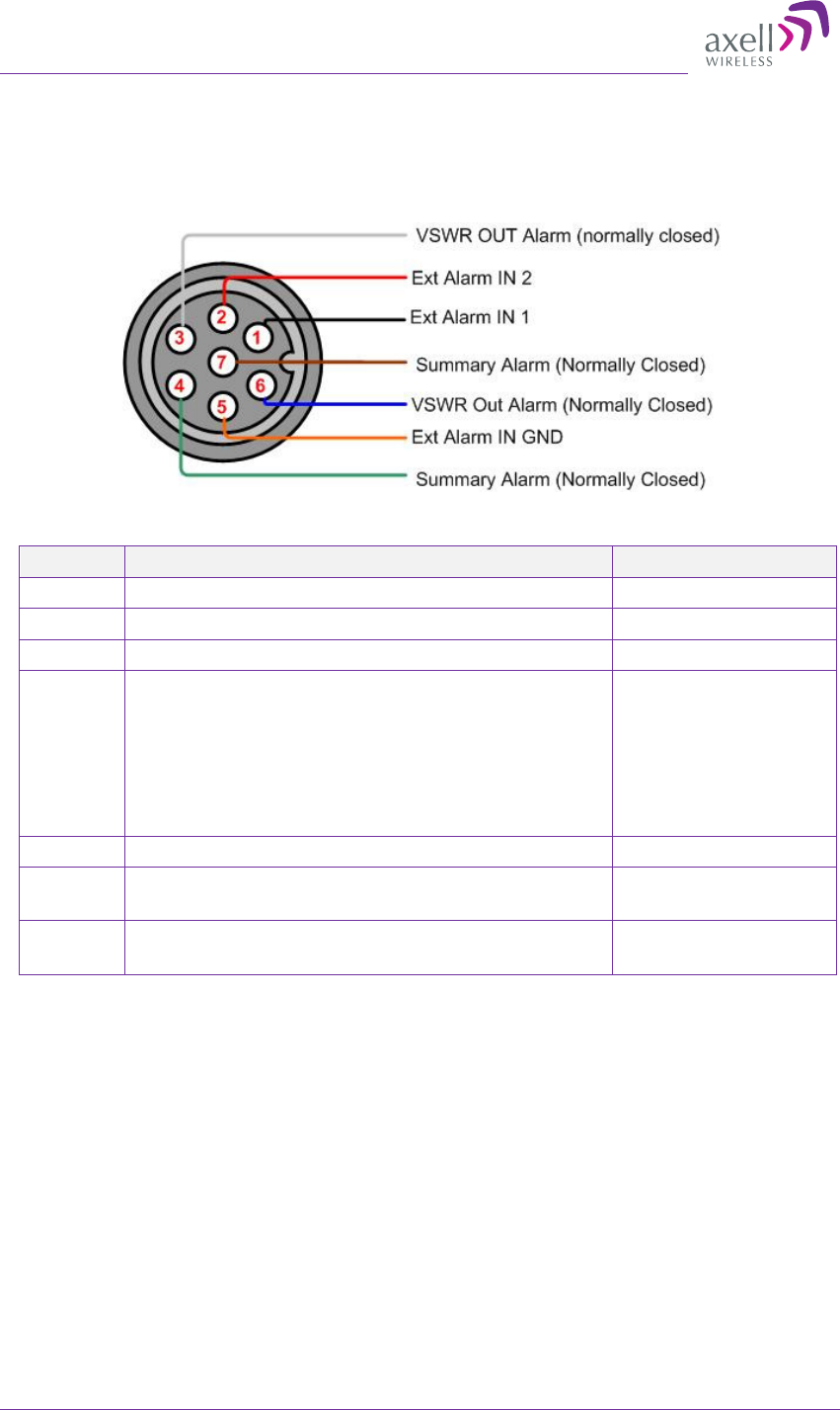
3.9.1 Alarm Connector Pinout
Each alarm status is recognized by a separate wire-pair, where the colored wires are
internally connected with a 4.7 K ohm resistor (serves as a pull up resistor to +5V. The
following figure shows the Alarm connector pinout.
Figure 3-11. Alarm Connector Pinout
Pin No. Signal Name Wire Color
1 External Alarm #1 Black
2 External Alarm #2 Red
3 Dry Contact VSWR Alarm (Normally Closed)* White
4 Dry Contact Summary Alarm (Normally
Closed)**
Triggered under one of the following conditions:
•
PA Current from FF
•
Temperature High or Built in Test
•
Power Failure
Green
5 GND for External Alarm Orange
6 Dry Contact Antenna Malfunction (VSWR) Alarm
(Normally Closed)*
Blue
7 Dry Contact Summary Alarm (Normally
Closed)**
Brown
*Dry Contact VSWR alarm connection is supported by a pair of wires (3,6).
** Dry Contact Summary alarm connection is supported by a pair of wires (4,7)
3.9.2 Load Restrictions
3.9.2.1 Alarm Dry Contact Output Restrictions
•
Maximum switching voltage: 220 VDC, 125 VAC
•
Maximum switching current: 2A
3.9.2.2 External Alarm Input Restrictions
•
Maximum repetitive reverse voltage: 28 V
•
Impedance load: 470 Ohm
•
To activate the alarm: verify it is configured to operate normally in LOW
(section 4.4), where low is short to GND.
Axell D-MBR 3007-3008-PS-NFPA
PRODUCT DESCRIPTION AND USER’S MANUAL
© Axell Wireless Ltd UMCD00013 Rev 2.2 25
3.9.3 Summary Alarms Trigger Criteria
The Summary alarm (pins 4 and 7) is triggered under one (or more) of the following:
•
PA Current from FF
•
Temperature High
•
Built-in Test
The summary alarm pins respond as follows:
STATUS External Alarm on USER connector RESULT
Power OFF Contacts 4,7 OPEN ALARM
Power ON Contacts 4,7 CLOSE NO ALARM
Summary
ALARM Active
Contacts 4,7 OPEN ALARM
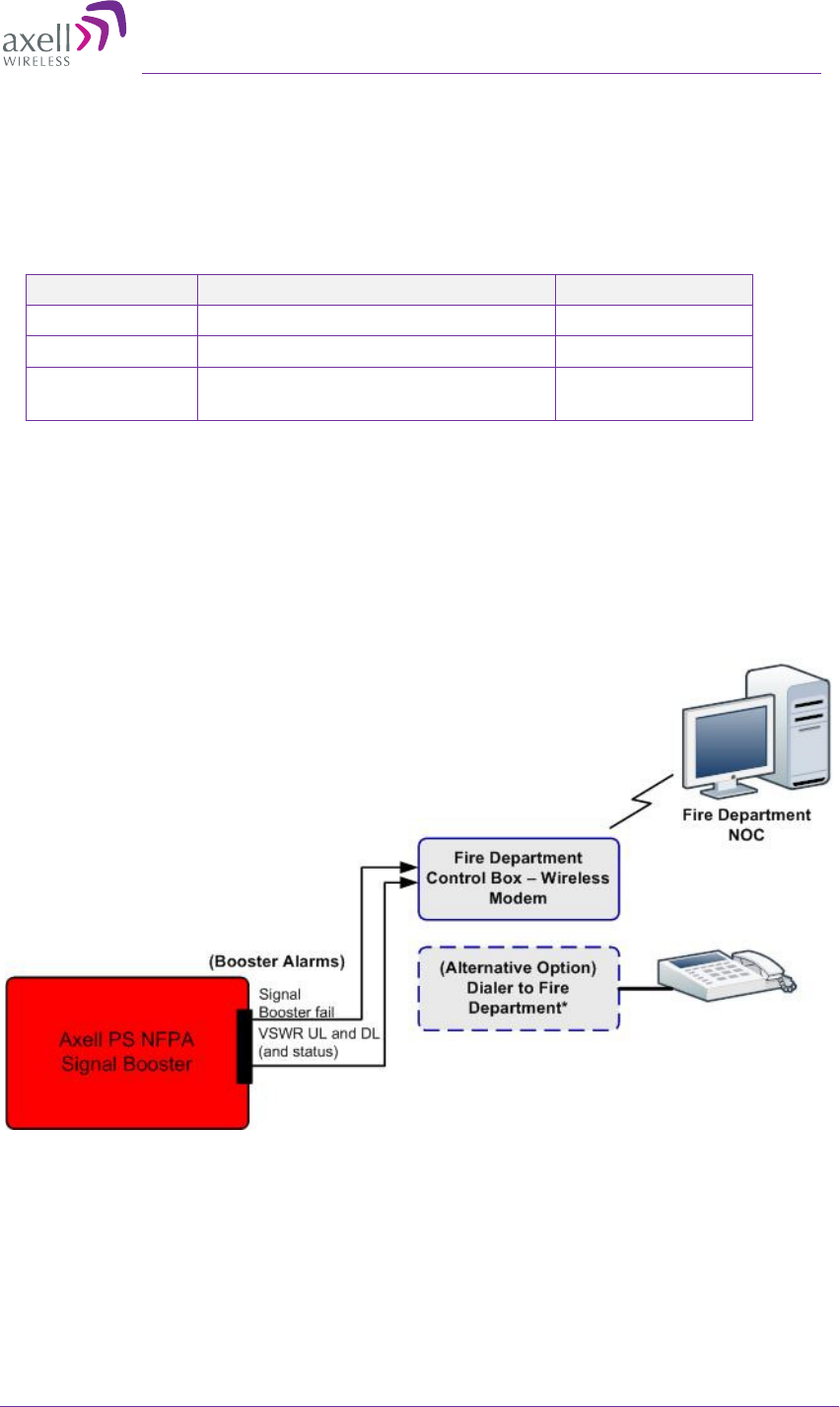
3.9.4 D-MBR-PS-NFPA Installation Alarm Connections
The Repeater Alarm connector contains two sets of dry contact alarms that are connected
to the Fire Department Control Box (see section 3.9.1 above).
•
VSWR (Pins 3,6)
•
Summary (Pins 4,7)
Figure 3-12. D-MBR PS NFPA Architecture
AXELL D-MBR 3007-3008-PS NFPA REPEATER
PRODUCT DESCRIPTION AND USER’S MANUAL
26 UMCD00013 Rev 2.2 © Axell Wireless Ltd
4 Initial Setup and Commissioning
This section describes the setup procedures for the D-MBR PS Repeater. The initial setup
procedure is performed through a Web connection from a computer on the same subnet,
using a cross-over Ethernet cable (supplied).
The setup procedure consists of the following steps:
1. Open a local Web session to the Repeater (this requires configuring the
communication parameters of the computer used).
2. If you are not familiar with the Axell Web Access application, we suggest you quickly
review the section on Navigating the Web GUI Application. It is only a couple of
pages and you will find it useful.
3. Define the Global Settings for each of the supported bands, and determine the
number of filters assigned to each band.
4. Enable and configure the relevant channels (Filter Switch tab).
5. Verify that no Alarms are generated.
6. Set the Repeater time and date.
7. Configure the external alarms.
8. (If relevant), configure the System IP Address.
4.1 Open a Session to the Repeater
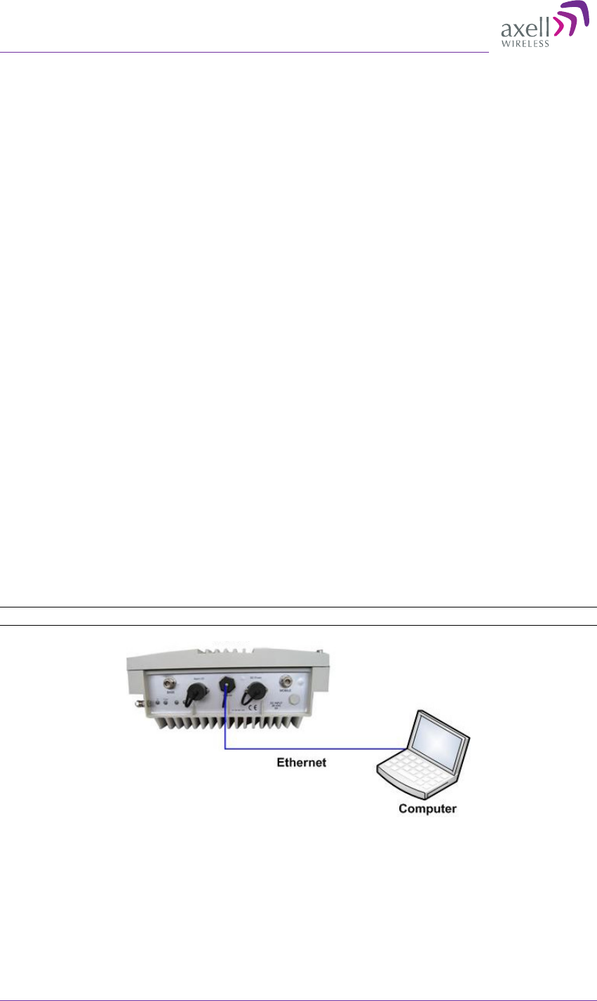
4.1.1 Connect the Repeater to the Computer
To open connect the Repeater to the Computer
Connect the Ethernet cable (supplied) between the front panel Ethernet port (see figure
below) and the computer Ethernet port.
Note: When performing a local connection, use the supplied Ethernet cross-cable (PN:
1579909499).
Figure 4-1. Connect Computer to Repeater via Ethernet
4.1.2 Configure the Computer Network Parameters
Configure the computer network parameters to communicate with the Repeater. Note that
the procedure may vary slightly depending on the operating system installed on your
computer. The following procedure is for Windows 7 OS.
Axell D-MBR 3007-3008-PS-NFPA
PRODUCT DESCRIPTION AND USER’S MANUAL
© Axell Wireless Ltd UMCD00013 Rev 2.2 27
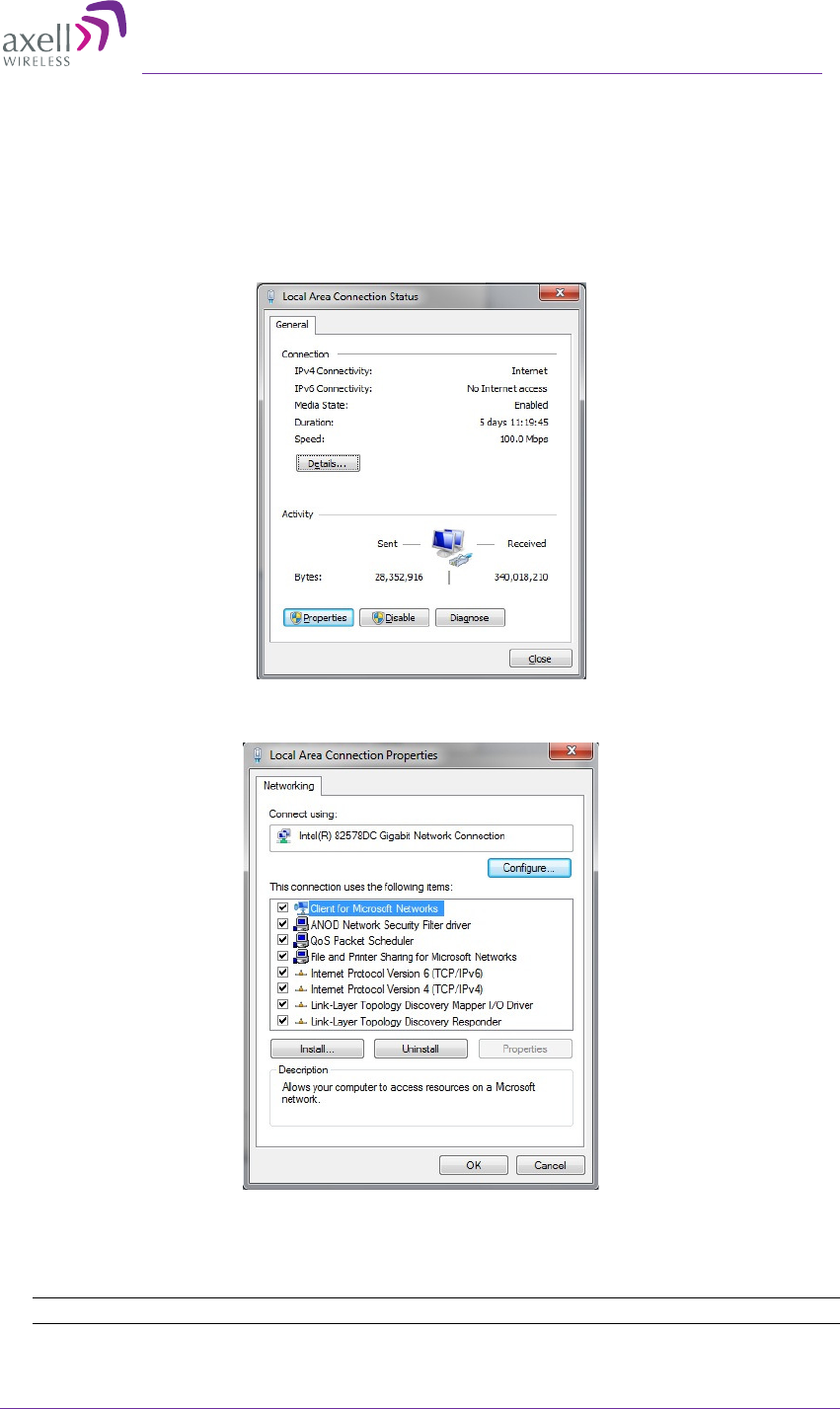
To configure the computer’s network parameters:
1. Click the Start menu and choose Control Panel.
2. In the Control Panel, click Network and Internet Connections.
3. Click Network and Sharing Center and then click Local Area Connection.
The Local Area Connections Status dialog appears with the General tab displayed
by default.
4. Click the Properties button in the displayed Local Area Connection Status dialog.
5. In the Items list, double-click Internet Protocol Version 4 (TCP*IPv4) item. The
Internet Protocol Version 4 (TCP/IPv4) Properties dialog appears.
Note: The Repeater is supplied with the default IP address 192.168.1.253.
AXELL D-MBR 3007-3008-PS NFPA REPEATER
PRODUCT DESCRIPTION AND USER’S MANUAL
28 UMCD00013 Rev 2.2 © Axell Wireless Ltd
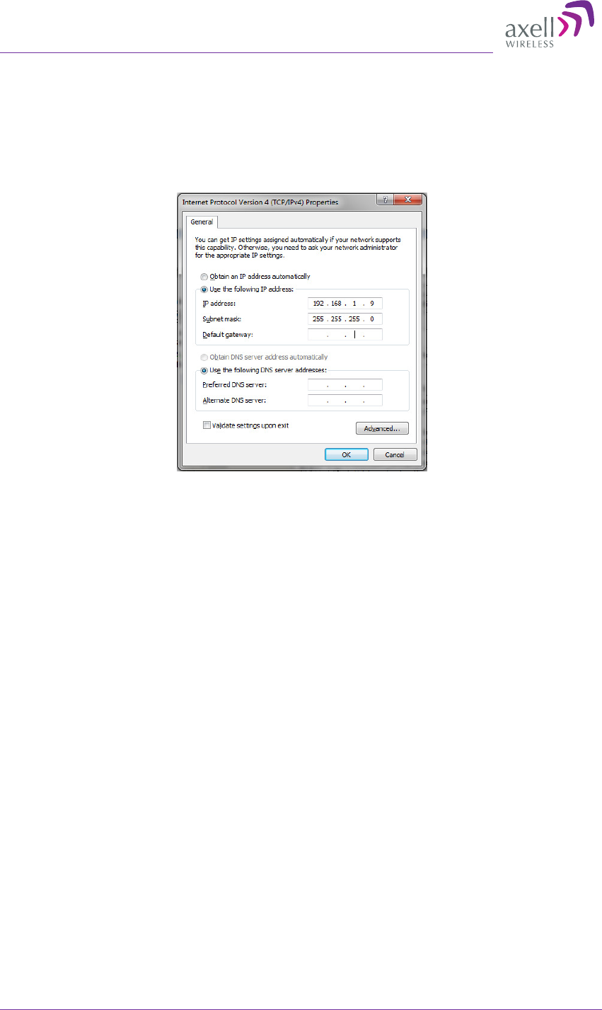
6. Assign your computer an IP address in the same subnet, in order to communicate
with the unit.
•
In the IP address area:
•
Enter the IP address 192.168.1.x, where ‘x’ can be any number between 2 and
250 inclusive. For example, (192.168.1.9)
•
Define the subnet mask as shown (255.255.255.0)
o
Click OK. The computer communication parameters are now defined
and you can open a session to the Repeater.
Axell D-MBR 3007-3008-PS-NFPA
PRODUCT DESCRIPTION AND USER’S MANUAL
© Axell Wireless Ltd UMCD00013 Rev 2.2 29
4.1.3 Login to the Repeater
NOTE: The Repeater is factory assigned the address 192.168.1.253. You will login for the first time
using this address and make the necessary modifications according to information provided by your
network administrator.
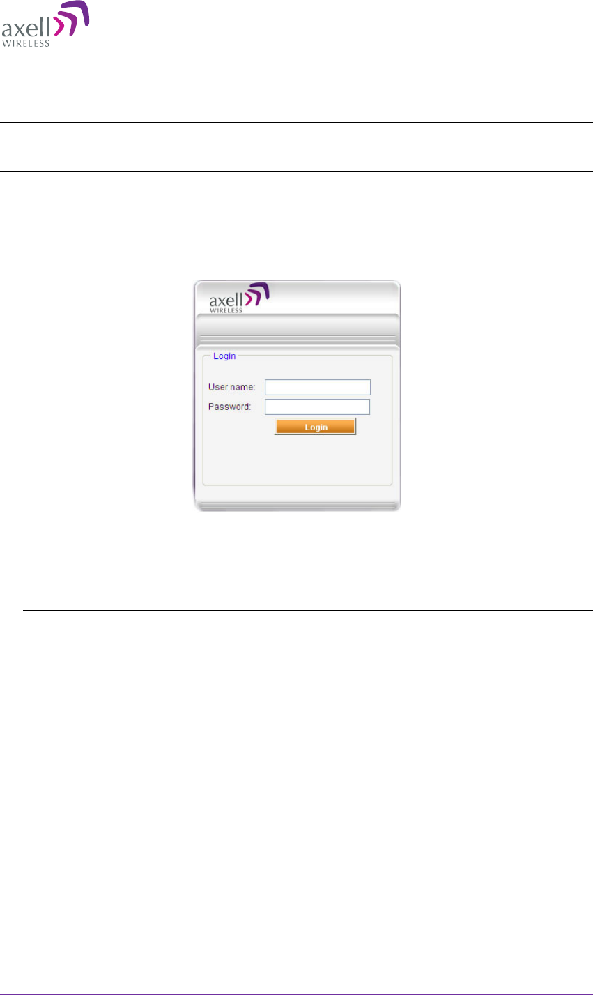
To login to the Repeater
1. Open a standard Flash-enabled browser (e.g. Explorer).
2. In the address line, enter the default (provided) IP address of the Repeater. A
session will be established with the Repeater and the login dialog will appear.
Figure 4-2. Login Prompt
3. Type the default User Name admin and the default Password admin
Note: Both User name and Password are case sensitive and must be entered with lower case
letters.
4. Click Login. The application main window appears.
AXELL D-MBR 3007-3008-PS NFPA REPEATER
PRODUCT DESCRIPTION AND USER’S MANUAL
30 UMCD00013 Rev 2.2 © Axell Wireless Ltd
4.2 Configuring RF Parameters and Channels
The gain range is up to 85dB for all bands and is set by default to its maximum value of
85dB.
NOTE: The gain will then be modified automatically to its optimum value by the SALC mechanism.
This mechanism performs gradual learning of traffic load characteristics and adjusts the Repeater RF
Gain accordingly. (See section 1.4 for more information on the SALC mechanism).
The following filter selection options are available:
NOTE: The available filter selection options can be viewed in the Band Info tab (section 5.2.2).
• Narrowband filters: 12.5 to 1,000 kHz (in 12.5KHz steps)
• Wideband filters: 200 to 20,000KHz (in 200KHz steps)
• 5MHz filters: 5,000KHz
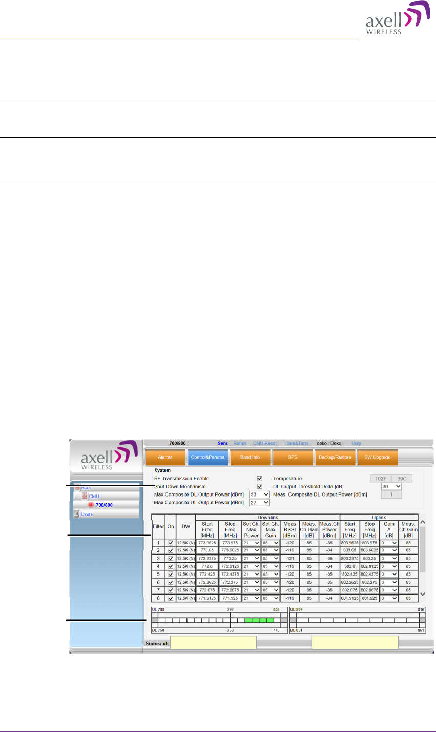
4.2.1 Control Params Tab
You can define up to 12 filters according to their bandwidth, power, gain and gain-delta
(used for noise control). The defined filters are graphically displayed in the lower part of
the screen.
To configure the signal level and channels
1. In the topology tree, click Root and then 700/800.
2. Click the Control&Params tab. The displayed window is divided into two main
areas:
• System – overall parameters for the selected service.
• Sub-band (filter) definitions – used to define up to 12 sub-bands and their RF
parameters.
• Sub-bands view – graphical display of defined sub-bands for the service.
Figure 4-3. Sub-band Allocation Configuration
Global RF
parameters
Define up to
12 filters
Graphical view
of defined
filters
700MHz filters 800MHz filters
Axell D-MBR 3007-3008-PS-NFPA
PRODUCT DESCRIPTION AND USER’S MANUAL
© Axell Wireless Ltd UMCD00013 Rev 2.2 31
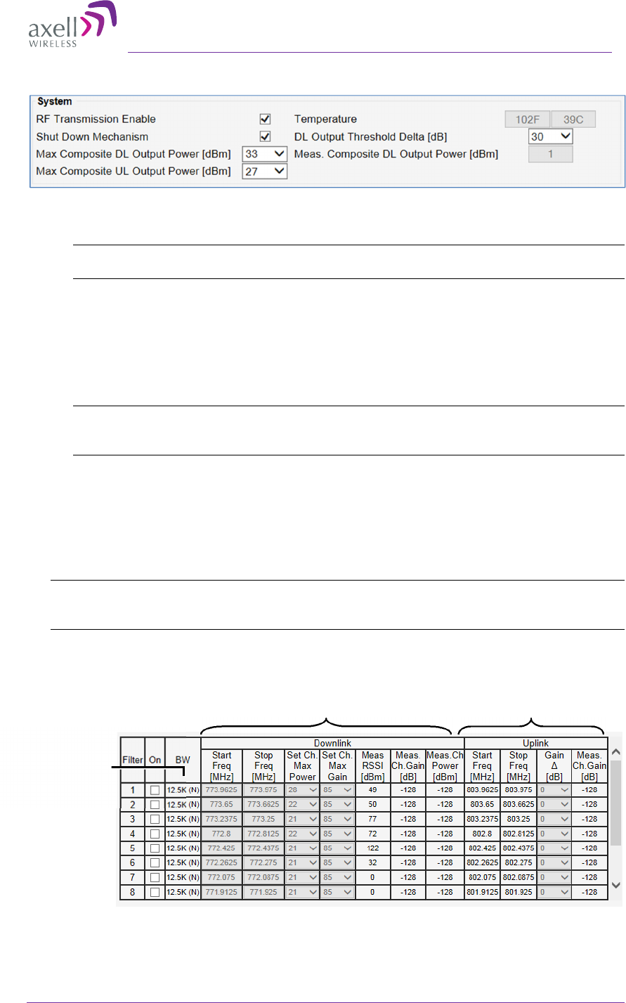
3. Set the System Level parameters:
• RF Transmission Enable – disables and enables unit RF transmission. Verify
that it is checked (RF transmission ON).
NOTE: RF transmission can be disabled by the system if the Shut Down mechanism is
enabled and the criteria activated the mechanism is fulfilled.
• Shut Down Mechanism – when enabled, the system automatically disables RF
transmission if an excessively high input power (from the BTS side) is detected.
The shut down criteria is valid only after a specific period of time that valid
input power level is exceeded. In that case:
o RF Transmission Parameter is unchecked (transmission is OFF)
o System Mute alarm (Alarms tab) is generated (RED).
NOTE: If the high input power issue is resolved, then it is necessary to enable RF
transmission by checkmarking the RF Transmission Enable parameter. In addition, reset
the System Mute alarm (click Ack).
• Max Composite DL Output Power – set according to your site requirements
and click Send. The Measured Composite DL Output Power is displayed in
the adjacent field. If the composite output power exceeds the defined value, the
Smart-ALC feature begins working.
• Set the Max Composite UL Output Power according to your site
requirements.
NOTE: The Temperature shows the Repeater’s ambient temperature. The DL Output Threshold
Delta (dB) shows the delta from DL Output Power, below which the alarm 'Donor power is too
low' is activated.
4. Checkmark ON for each filter to be configured. The configuration parameters in that
row will be available.
Downlink Channels Uplink Channels
Defined BW:
Narrow band (N)
or
Wideband (W)
AXELL D-MBR 3007-3008-PS NFPA REPEATER
PRODUCT DESCRIPTION AND USER’S MANUAL
32 UMCD00013 Rev 2.2 © Axell Wireless Ltd
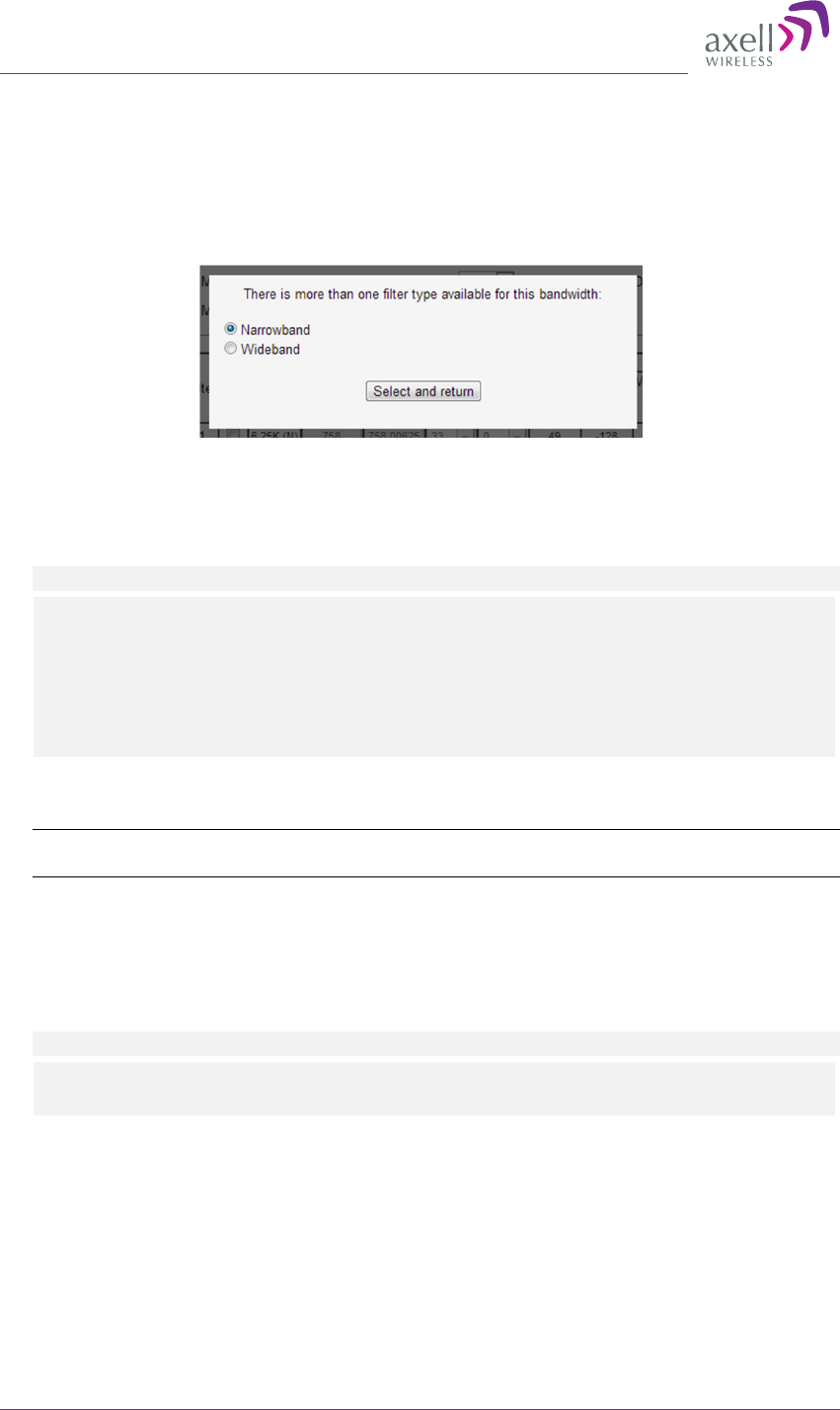
5. Define the Downlink Channels:
• Set the Start and Stop DL Frequency (MHz). (The Uplink Start and Stop
frequencies will be automatically allocated.)
• Sub-band resolutions ranging between 200KHz and 1MHz can be allocated to a
narrowband or wideband filter. In this case, you will be prompted to select the
filter type
o Select the filter type and click Select and Return.
o Click Send at the top of the screen.
• Set Max Gain: change the default value (maximum) according to the
measured/calculated input power and isolation measurements.
More information on DL sub-band parameters:
• DL Set Ch. Max. Gain - Sets the power for the antennas. Recommended
Maximum Gain setting is approximately 16 dB less than the isolation between
the service and donor antennas.
• DL Measured RSSI - measured DL signal.
• DL Measured Ch. Gain - measured DL Gain (dB) for the selected sub-band.
• DL Measured Ch. Power - measured Power (dBm) for the selected sub-band.
6. Set the Uplink parameters:
NOTE: The uplink channels are automatically allocated according to the downlink channel
definitions.
If the site NOISE LEVEL causes interference, adjust the noise level as follows:
• Adjust the Gain Delta parameter – this sets the delta between the uplink and
downlink gain (so the uplink gain is relatively lower than the downlink gain.
• Click Send.
• Repeat the procedure until the desired coverage is achieved.
More information on DL sub-band parameters:
• UL Gain ∆ - used for noise control. Sets the difference between UL and DL gain.
• UL Measured Ch. Gain - measured UL Gain (dB) for the selected sub-band.
7. Click Send (top window area option).
Axell D-MBR 3007-3008-PS-NFPA
PRODUCT DESCRIPTION AND USER’S MANUAL
© Axell Wireless Ltd UMCD00013 Rev 2.2 33
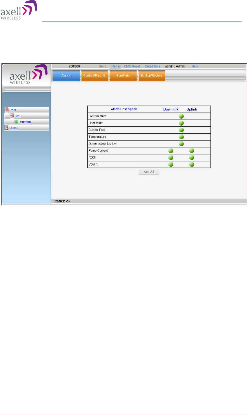
8. After the channels have been configured and the required coverage is attained for
the location, verify that no Alarms are generated:
•
Click the Alarms tab
•
Verify that all the indicators are GREEN in the Alarms tab
Figure 4-4. Alarms Dialog
AXELL D-MBR 3007-3008-PS NFPA REPEATER
PRODUCT DESCRIPTION AND USER’S MANUAL
34 UMCD00013 Rev 2.2 © Axell Wireless Ltd
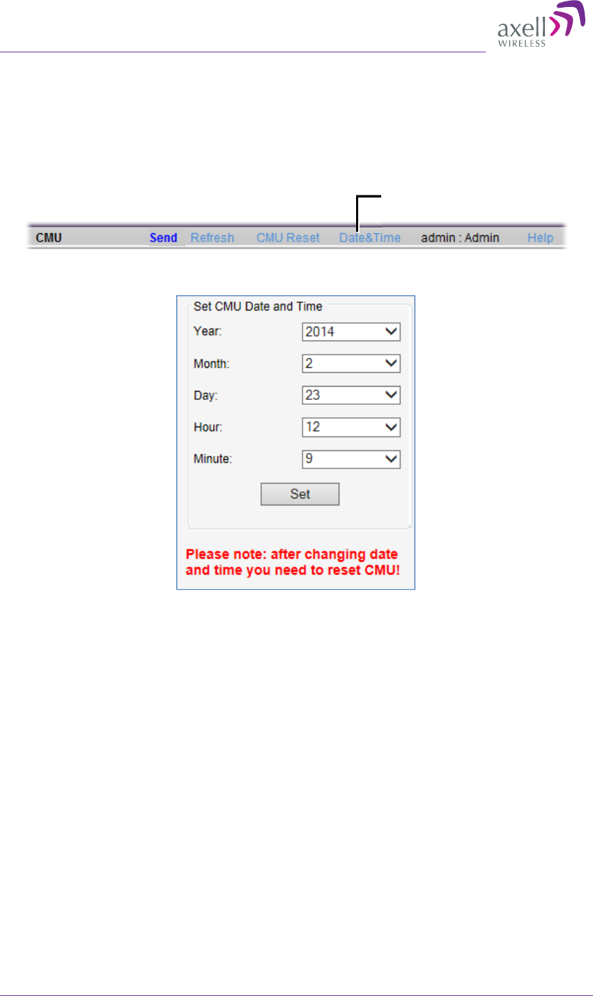
4.3 Setting Date and Time
It is important to set the correct date and time on the unit since this provides the
timestamp for each logged event and alarm.
To set the Repeaters date and time
1. Click on CMU in the tree pane.
2. Click on Date & Time in the menu bar.
The following dialog appears.
Figure 4-5. Date & Time Settings Dialog
3. Set the date and time parameters and click on Set in the dialog and then Send at
the top of the screen
4. Click the CMU Reset button in the main menu (shown above).
Click here
Axell D-MBR 3007-3008-PS-NFPA
PRODUCT DESCRIPTION AND USER’S MANUAL
© Axell Wireless Ltd UMCD00013 Rev 2.2 35
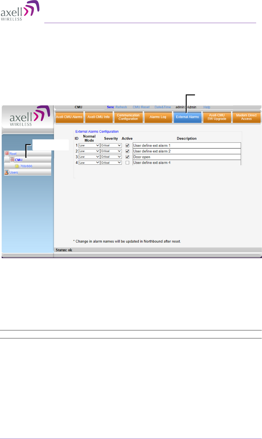
4.4 Configuring the External Alarms
Any connected external alarms (section 3.9) must be enabled and configured according
to the instructions provided in this section.
To configure external alarms
1. Click on CMU in the tree pane and select the External Alarms tab. The following
dialog appears.
Figure 4-6. External Alarm Configuration Dialog
2. For each connected alarm:
• Checkmark the Active checkbox.
• Verify the alarm Normal Mode is set to Low.
• Set the alarm Severity as Critical, Major or Minor
• In the Description field, assign the alarm an identifiable name (e.g. Door
open).
NOTE: Triggered external alarms are displayed in the Axell-CMU-Alarms tab.
Click CMU
External
Alarms tab
AXELL D-MBR 3007-3008-PS NFPA REPEATER
PRODUCT DESCRIPTION AND USER’S MANUAL
36 UMCD00013 Rev 2.2 © Axell Wireless Ltd
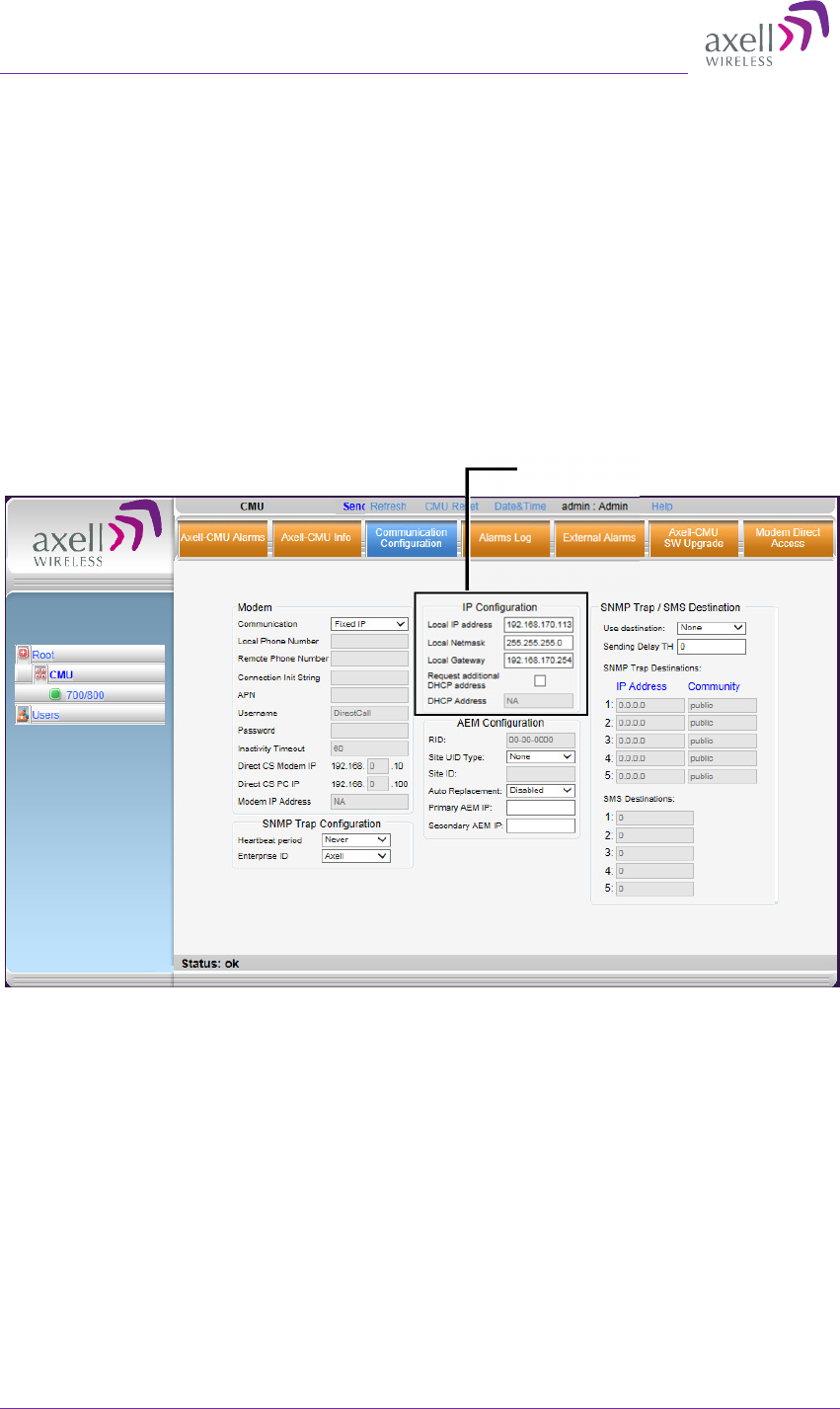
4.5 Setting the IP Address
The Repeater supports both Static and DHCP addresses. A unique technology enables
applying both types to the same Ethernet port. Both addresses may enable local and
remote management.
• Local IP Address – Static IP assigned by the user to the system. The default Static IP
address is 192.168.1.253. It is highly recommended to preserve this setup. In case
of a change, make sure you record the newly assign IP.
• DHCP Address – address assigned by DHCP server – used for remote management
via an Ethernet connection.
To configure the IP Address
1. Click on CMU in the tree pane and select the Communication Configuration tab.
The following dialog appears.
Figure 4-7. Communication Configuration Dialog
2. To assign the unit addresses (in IP Configuration area):
• Local address - in the IP Configuration area, assign the unit the IP address,
Netmask and Gateway parameters provided by your system administrator.
• DHCP server address – checkmark the option Request Additional DHCP Address.
The assigned address can be seen in the DHCP Address field.
3. Click Send.
IP Address
Axell D-MBR 3007-3008-PS-NFPA
PRODUCT DESCRIPTION AND USER’S MANUAL
© Axell Wireless Ltd UMCD00013 Rev 2.2 37
5 Administrative Operations
The following administrative operations are described in this section:
• User Management – defining and changing users and passwords.
• Viewing the Repeater information such as software and hardware versions, serial
number.
• Software upgrade
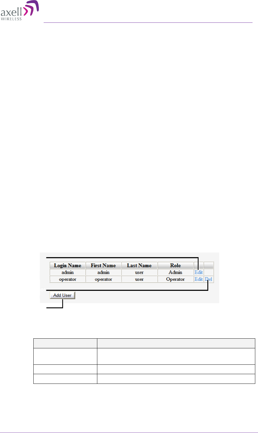
5.1 User Management
This section describes how to perform the user management operations. By default, two
users belonging to one of three authentication levels are defined on the Repeater. You
may add new users, modify or delete existing users.
5.1.1 User Levels
Two user levels are available:
• Admin – has access to all administration and configuration options, including user
management. (Default Password admin and default User Name admin.)
• Operator – has access to all configuration options except for the Users list or the
Loaders screen.
5.1.2 Viewing the List of Defined Users
To display the User Administration pane
From the Tree Pane, select Users. The list of users is displayed in the Configuration Pane
according to the identifying information and authentication level (Role).
Figure 5-1. User Administration Pane
The following table provides a description of the Users dialog options.
Option Description
Add User (button) Adds a new user with to user defined access level
and password.
Del(ete) Deletes a selected user from the list.
Edit Enables changing the definitions of an existing user.
Edit user
Delete user
Add user
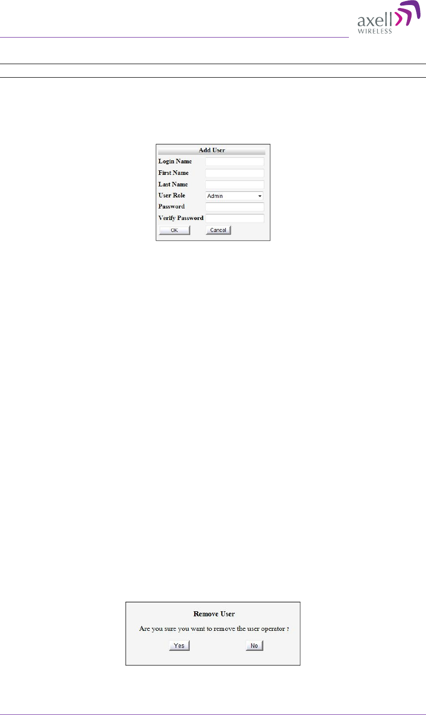
AXELL D-MBR 3007-3008-PS NFPA REPEATER
PRODUCT DESCRIPTION AND USER’S MANUAL
38 UMCD00013 Rev 2.2 © Axell Wireless Ltd
5.1.3 Adding Users
NOTE: User name and password entries are case sensitive.
To add a user
1. From the Tree Pane, select Users. The list of users is displayed in the User's Pane.
2. From the User's Pane, click Add User. The Add User dialog box is displayed.
Figure 5-2. Add User
3. Enter the Login Name – name used by user to login.
4. Type the user's First Name and Last Name – used to identify the user.
5. Select the User Role – access level. This defines the operations that the user will be
able to perform.
6. Enter the Password and in Verify Password enter the password again for
verification.
7. Click OK.
5.1.4 Editing a User
To modify user definitions
1. From the Tree Pane, select Users. The list of users is displayed in the User's
Pane.
2. Select the User to be edited in the list.
3. Click Edit. The user definitions dialog appears.
4. Make the required changes and click OK.
5.1.5 Deleting a User
To delete a user
1. From the Tree Pane Select Users. The list of users is displayed in the User's Pane.
2. Select the User to be deleted in the list.
3. From the User's Pane, click Del. An authorization message dialog box is displayed.
Figure 5-3. Remove User
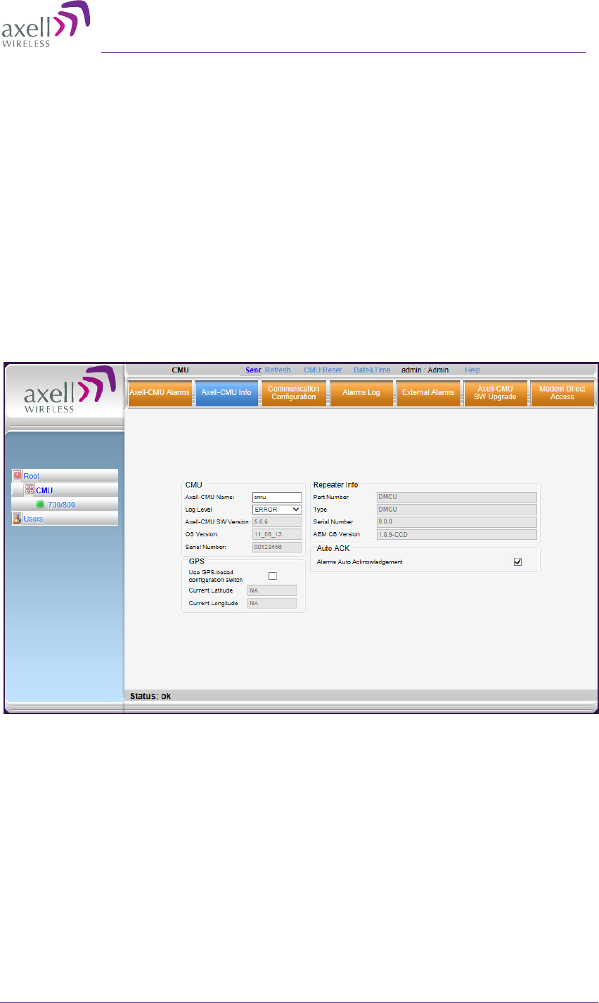
Axell D-MBR 3007-3008-PS-NFPA
PRODUCT DESCRIPTION AND USER’S MANUAL
© Axell Wireless Ltd UMCD00013 Rev 2.2 39
4. Click Yes. The User’s name is removed from the list.
5.2 Repeater and Band Level Information
The Web GUI provides Repeater level information (via the CMU Info tab) and band level
information (via the Band Info tab).
5.2.1 Viewing Repeater Level Information
Use the CMU Info screen to view the hardware and software versions of the Axell
Repeater and to assign the Repeater a recognizable name.
To access the Band Information window
In the Tree Pane, select CMU and click the Axell CMU Info tab.
Use the Log Level to set the minimum fault level that is logged. Other fields provide
version and identification information.
Figure 5-4. CMU Level Info
5.2.2 Viewing Band Level Info
Use the Repeater Information screen to view the hardware and software versions of
the Axell D-MBR Repeater and to assign the Repeater a recognizable name.
To access the Repeater Information window
1. From the Tree Pane, select the Band element (i.e. 700/800).
2. Select the Band Info tab. The relevant parameters are displayed.
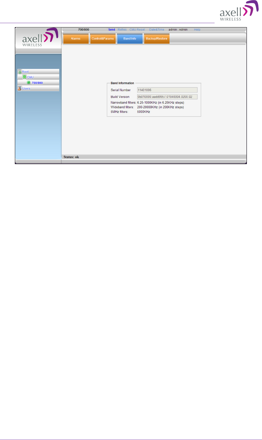
AXELL D-MBR 3007-3008-PS NFPA REPEATER
PRODUCT DESCRIPTION AND USER’S MANUAL
40 UMCD00013 Rev 2.2 © Axell Wireless Ltd
Figure 5-5. Band Level Information
5.3 Configuration Files Backup/Restore
The D-MBR 3007-3008-PS Web GUI management application enables the backup and
restore of the repeater configuration files. The procedures are performed via the
Backup/Restore tab.
A number of configuration files can be stored on the Repeater for access at any time.
You can perform the following operations:
• Backup of the currently active configuration
• Restoring a previously saved file
• Uploading a configuration file from another location to the Repeater
• Downloading a configuration file from the Repeater to another location
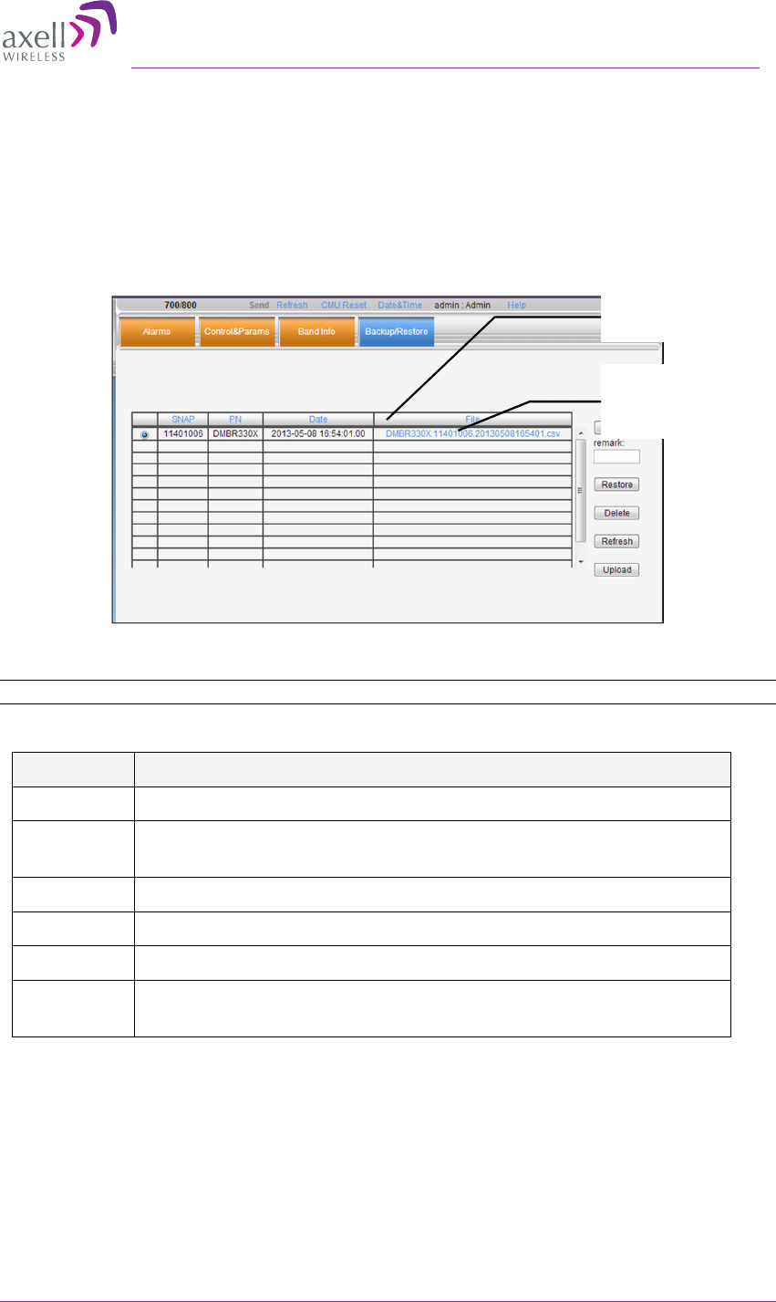
Axell D-MBR 3007-3008-PS-NFPA
PRODUCT DESCRIPTION AND USER’S MANUAL
© Axell Wireless Ltd UMCD00013 Rev 2.2 41
5.3.1 The Backup/Restore Tab
To access Backup/Restore tab
From the Tree Pane, select the relevant band and click the Backup/Restore tab. The
following screen appears.
The screen displays the configuration files currently available on the Repeater. Each file
is displayed along with the Repeater serial number and is named by default according to
the date on which it was created (a user defined name can also be assigned).
Figure 5-6. Backup and Restore
NOTE: Click links to download files and save to another location.
The file management buttons provide the following options:
Button Description
Backup Backup the currently running configuration file
Remark User defined name that will be assigned to the file saved using the
Backup file. (Instead of the system assigned name).
Restore Activates the system with the selected file.
Delete Deletes the selected file.
Refresh Refreshes the displayed list of files.
Upload Enables uploading a configuration file from another location to the
Repeater.
File with user
assigned name
(Muted)
Currently
saved files
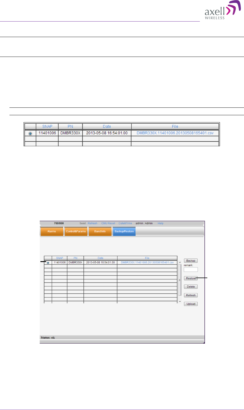
AXELL D-MBR 3007-3008-PS NFPA REPEATER
PRODUCT DESCRIPTION AND USER’S MANUAL
42 UMCD00013 Rev 2.2 © Axell Wireless Ltd
5.3.2 Backup of Repeater Configuration
NOTE: The backed file will automatically be assigned a name according to the backup date and unit
ID. The name cannot be modified while the backup file is saved onto the Repeater. However, before
the backup procedure begins, the user may assign the file a recognizable name via the Remark field.
To perform backup procedure
1. To assign the configuration file a recognizable name, enter a name in the remark
field. Otherwise, the file will be assigned a name by the system.
2. Click the Backup button located on the right-hand side of the tab.
3. The file will be added to the table displayed in the Backup/Restore tab.
Note: The file name (under File) is a link that enables uploading the file to another location.
Figure 5-7. Backup Repeater Info
5.3.3 Restoring Previous Repeater Configuration
To restore previous configuration
1. Select the required configuration file (enable corresponding radio button) from the
available list in the Backup/Restore tab.
2. Click the Restore button.
Figure 5-8. Restore Repeater Info
3. Click on the Control and Params tab and verify that the required configuration
settings have been restored.
Selected
configuration
file
Rest
ore
button

Axell D-MBR 3007-3008-PS-NFPA
PRODUCT DESCRIPTION AND USER’S MANUAL
© Axell Wireless Ltd UMCD00013 Rev 2.2 43
5.3.4 Uploading New Configuration File to Repeater
To upload configuration file to Repeater
1. Click the Upload button.
2. Select the file from the Browse dialog and click Open.
3. The file appears in the list displayed in the Backup/Restore table.
5.3.5 Saving Configuration File to Computer
To save a configuration file from the available list in the Backup/Restore table to a location in a
connected computer:
•
Select file from list.
•
Click the link in the File column.
•
Select the location in the Browse dialog.
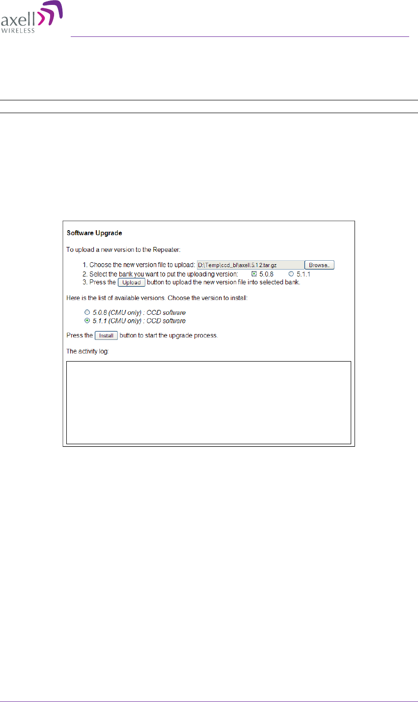
AXELL D-MBR 3007-3008-PS NFPA REPEATER
PRODUCT DESCRIPTION AND USER’S MANUAL
© Axell Wireless Ltd UMCD00013 Rev 2.2 44
5.4 CMU Software Upgrade
The procedure described in this section is used to upgrade the repeater CMU.
NOTE: This procedure is performed for every new management version.
The CMU SW upgrade procedure consists of loading the new software version and
installing it in the CMU. The CMU can store two versions on two separate data banks
enabling restore to a previous version.
To Upgrade the CMU SW
1. In the Tree Pane, select CMU and click the Axell CMU SW Upgrade tab. The
following screen appears (the Browse field will be empty).
2. Choose and save the file onto the Repeater:
•
(1) Click Browse to search for the location and choose the new software file. It
will be displayed adjacent to the Browse button.
•
(2) Select the bank where the file will be stored. (Before it is populated the
bank will be named ‘slot’. After it is populated, it will take on the name of the
stored software version). Any existing software file will be replaced.
•
(3) Press Upload to save the file to the selected bank (slot). The available
software files to choose from will be listed.
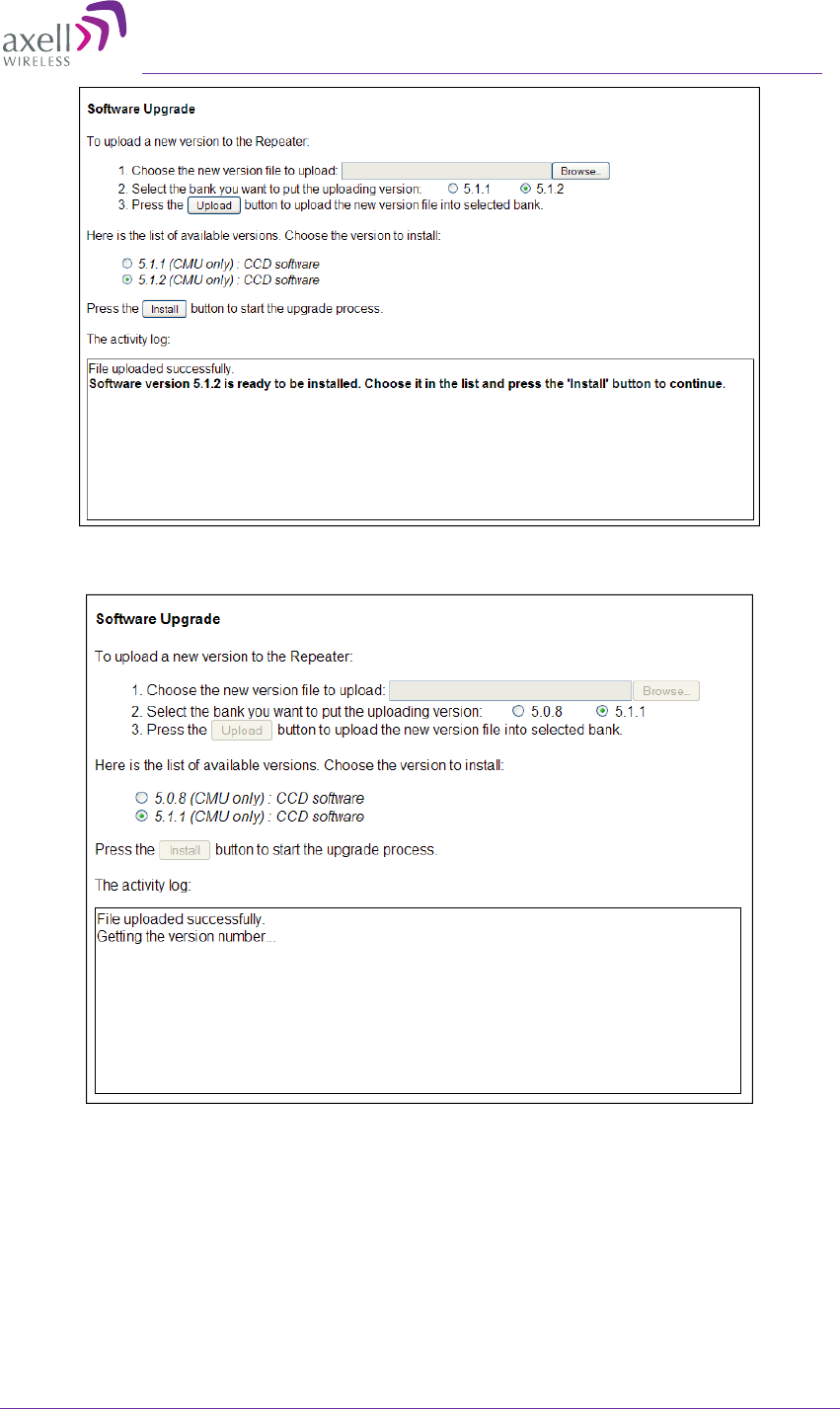
Axell D-MBR 3007-3008-PS-NFPA
PRODUCT DESCRIPTION AND USER’S MANUAL
© Axell Wireless Ltd UMCD00013 Rev 2.2 45
3. Choose the required software file and click Install.
4. The Activity Log will indicate status and upgrade completion.
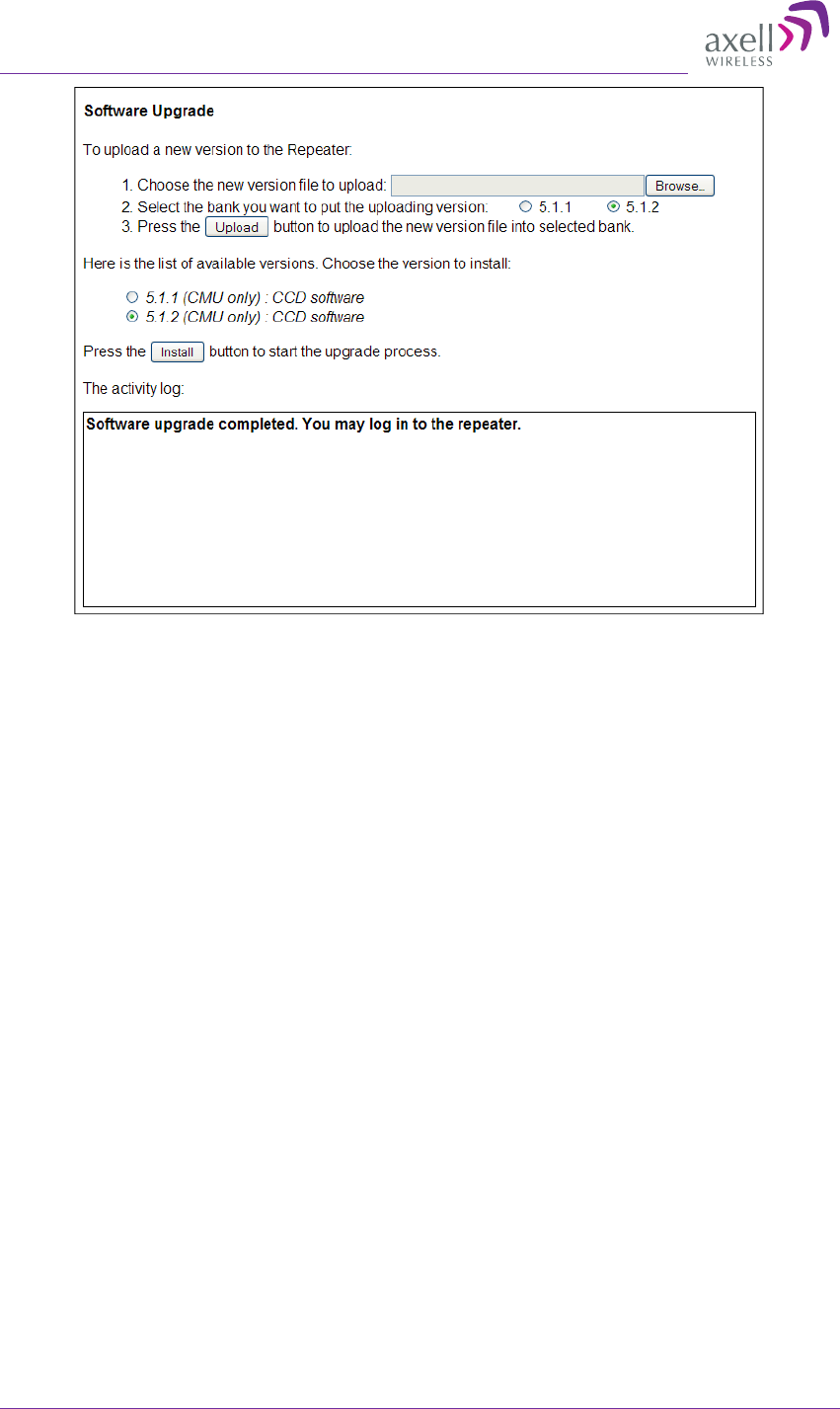
AXELL D-MBR 3007-3008-PS NFPA REPEATER
PRODUCT DESCRIPTION AND USER’S MANUAL
46 UMCD00013 Rev 2.2 © Axell Wireless Ltd
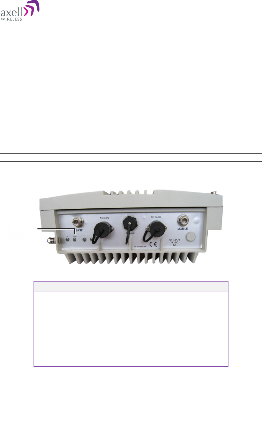
Axell D-MBR 3007-3008-PS-NFPA
PRODUCT DESCRIPTION AND USER’S MANUAL
© Axell Wireless Ltd UMCD00013 Rev 2.2 47
6 Monitoring and Troubleshooting
The D-MBR 3007-3008-PS-NFPA provides two types of indications of failure:
• Front panel LED
• Alarms screen in Web access application
• Alarms Log – used to view a record of past generated alarms
The following sections provide a description of the troubleshooting procedures according
to the Alarms and log options.
6.1 Front Panel LED
The repeater supports ONE status LED on its front panel. The LED color and steady or
blinking status reflects system status (normal or faulty) and fault level as described in this
section.
NOTE: The NFPA unit is colored RED.
6-1. Axell D-MBR 3007-3008-PS NFPA Front Panel Interfaces
LED color Description – section 6.2.
Red
• System Mute
• User Mute
• PAmp Current
• Temperature High Level
• Built in test
Orange RSSI DL
VSWR(DL&UL)
Blinking green Power Below Threshold
LED (only
one LED is
relevant)
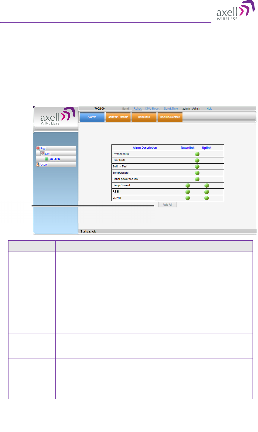
AXELL D-MBR 3007-3008-PS NFPA REPEATER
PRODUCT DESCRIPTION AND USER’S MANUAL
48 UMCD00013 Rev 2.2 © Axell Wireless Ltd
6.2 GUI Alarm Descriptions
The Alarms tab provides the alarms generated by the Repeater, enabling the user to
monitor the system operation.
To access the Alarms window
From the Tree Pane, select the 700/800 item and choose the Alarms tab. Note that some
alarms are dedicated for the UL and DL and other alarms are common to the UL and DL.
NOTE: Use the Ack All button to simultaneously acknowledge all triggered alarms.
Alarm Fault and most probable cause and Recommendation
System Mute Description. Generates an alarm when Repeater amplification is
automatically muted.
Possible causes:
• Temperature failure
• Synthesizer failure
• Hardware failure
• High RSSI power DL/UL when the shutdown mechanism is on
(Control and Params tab).
Recommended action: Check the LEDs and other alarm from
the Repeater. Contact Axell Support
User Mute Description: Manual shutdown performed by operator from the
Web GUI.
Recommended action: Review unit’s log
Built In Test Possible causes: Hardware failure, Circuitry failure, Software
failure
Recommended action: Contact Axell Support
Temperature Description: Repeater temperature is exceedingly high due to
excessive external heat.
Ack All
triggered
alarms

Axell D-MBR 3007-3008-PS-NFPA
PRODUCT DESCRIPTION AND USER’S MANUAL
© Axell Wireless Ltd UMCD00013 Rev 2.2 49
Alarm Fault and most probable cause and Recommendation
Recommended action: Check the Repeater case for external
causes (sun, hot environment, air flow is blocked). Eliminate the
reason for excessive heat.
Donor Power
Too Low
Description: Signal from the Donor antenna (DL) is too low -
relatively to the desired output signal configured by the user.
Recommended action:
•
Check the Donor/Base connections and antenna position.
•
Check the signal level of the Donor/Base antenna.
• If the Donor Power Too Low alarm is still raised, then you can
raise, the value of the DL Output Threshold Delta[dBm] as
needed.
(PAmp)
Current
Description: Power Amplifier current is not within limits (too
high or too low). If the Mute option is enabled, then this is not a
fault since it indicates low Power Amplifier current caused by the
mute.
Recommended action: Check the LEDs status in the Repeater
and Contact Axell service support.
RSSI Description: Generates an alarm when a high donor input signal
causes system gain reduction
VSWR Description: This alarm is triggered when the return loss of the
Downlink or Uplink antenna or cable connection exceed the
allowed limit.
This alarm provides an indication of the status of the
cable/antenna connected to the antenna. If a cable/antenna is
defective, the VSWR is decreased and the alarm is triggered.
Recommended action: Check the cable.
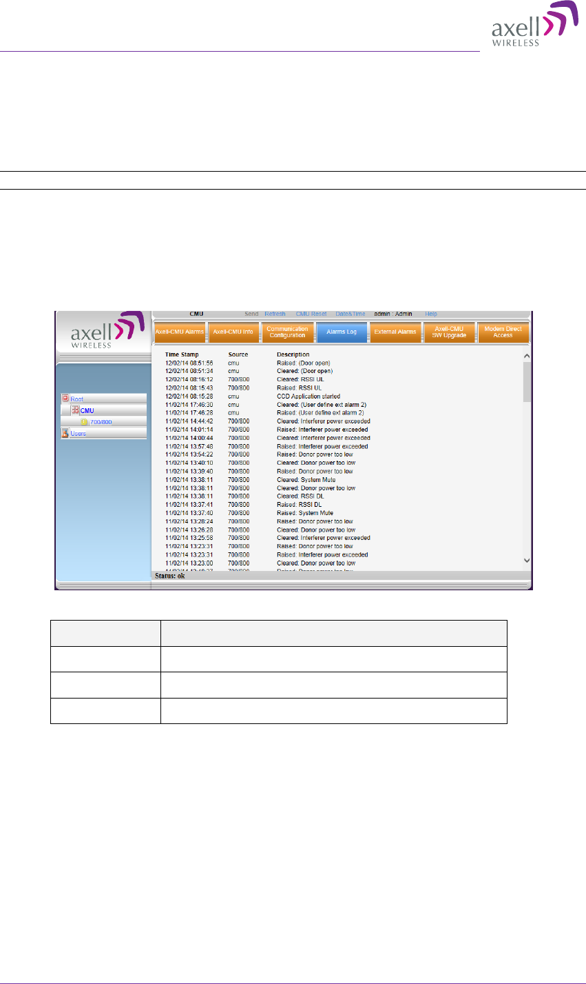
AXELL D-MBR 3007-3008-PS NFPA REPEATER
PRODUCT DESCRIPTION AND USER’S MANUAL
50 UMCD00013 Rev 2.2 © Axell Wireless Ltd
6.3 Alarms Log
The Alarms Logs screen lists the alarms (events) that have occurred. The CMU maintains
log files listing every alarm triggered and in the Repeater. This screen provides an analysis
tool to get information of any event that has occurred, its originator, when, if they return,
and their type.
NOTE: Set the clock in order to synchronize the events time of occurrence (see 4.3).
To view the CMU log screen:
1. Open and login to the Web application.
2. From the Tree Pane, select CMU.
3. Click Alarms Logs. CMU displays the Alarms Log Table.
Figure 6-2. CMU Alarms Log Tab
Item Description
Time Stamp The date and time the alarm was created
Source Source of alarm.
Description Description of event that caused the alarm

Axell D-MBR 3007-3008-PS-NFPA
PRODUCT DESCRIPTION AND USER’S MANUAL
© Axell Wireless Ltd UMCD00013 Rev 2.2 51
Appendix A: Specifications
This appendix provides the electrical, mechanical and environmental specifications of the
Axell D-MBR 3007-3008-PS-NFPA.
Electrical Downlink Uplink
Frequency Range:
SMR 700MHz ,D block
SMR 700MHz
SMR 800MHz
758 - 763 MHz
763 - 775 MHz
851 - 861 MHz
788 - 793 MHz
793 - 805 MHz
806 - 816 MHz
Passband Max Gain 85dB
Passband attenuation range 30dB @ 1dB steps 20dB @ 1dB steps
Passband Ripple ± 2.5 dB ± 2.5 dB
Gain attenuation range 30dB 20dB
Filter Bandwidth (SMR 700MHz) (*)
Filter Bandwidth (SMR 800MHz) (*)
Programmable 12.5KHz to 1MHz at 12.5KHz
steps, 1MHz-17MHz at 200KHz steps
Programmable 12.5KHz to 1MHz at 12.5KHz
steps, 1MHz-10MHz at 200KHz steps
Number of filters( SMR 700& 800) 12
Composite Output Power SMR700MHz
+30 dBm +27 dBm
Composite Output Power SMR800MHz
+30 dBm +27 dBm
Noise Figure @ Maximum Gain 5.0 dB
General
Dimensions W x D x H 13.78” x 18.1” x 5.7” (350 mm x 460 mm x
145 mm)
Power Supply 90 to 260 VAC or 48VDC
Power Consumption <130 W
Total RF Input Power (no damage) +10 dBm
Impedance Level 50 Ohm
RF Connector N-type, Female
VSWR 1.5:1 maximum
Compliance IC/FCC
Environmental
Operating Temperature -5 to 122° F (-10° C to +50° C)
Humidity 10% to 90% Condensed
Weight 28.8 lbs. (13kg)
Enclosure Aluminum (NEMA4/IP-65)

AXELL D-MBR 3007-3008-PS NFPA REPEATER
PRODUCT DESCRIPTION AND USER’S MANUAL
52 UMCD00013 Rev 2.2 © Axell Wireless Ltd
(*)Every filter above 10 MHz utilizes 2 FPGA resources
Ordering Information
IDENTIFICATION DESCRIPTION PART NUMBER
D-MBR 3007-3008
PS NFPA AC
Digital Multi Channel Selective Signal
Booster 700/800 12 channels, 30dBm
composite per band, 85dB gain, AC and
DC powering with NFPA and IFC
compliant Alarm Outputs and red
painted case.
D-MBR 7/8 PS
30DBM 12 FIL NFPA
RED
D-MBR 3007-3008
PS NFPA DC
Digital Multi Channel Selective Signal
Booster 700/800 12 channels, 30dBm
composite per band, 85dB gain, DC
powering with NFPA and IFC compliant
Alarm Outputs and red painted case.
D-MBR 7/8 PS
30DBM 12F NFPA DC
12 hour battery Battery back-up unit for 12 hours BBU-400W-12H
24 hour battery Battery back-up unit for 24 hours BBU-400W-24H
PSTN Dialer PSTN Dialer for NFPA Signal Booster PSTN-DIALER