PBE Europe as Axell Wireless DSBR3709S D-SBR3709S 900 MHz Booster User Manual
Axell Wireless D-SBR3709S 900 MHz Booster
UserManual.wiki
>
PBE Europe as Axell Wireless
>
DSBR3709S User Manual
User manual
Navigation menu
Upload a User Manual
Namespaces
Wiki Guide
HTML
PDF
Info
Views
User Manual
Discussion / Help
Navigation

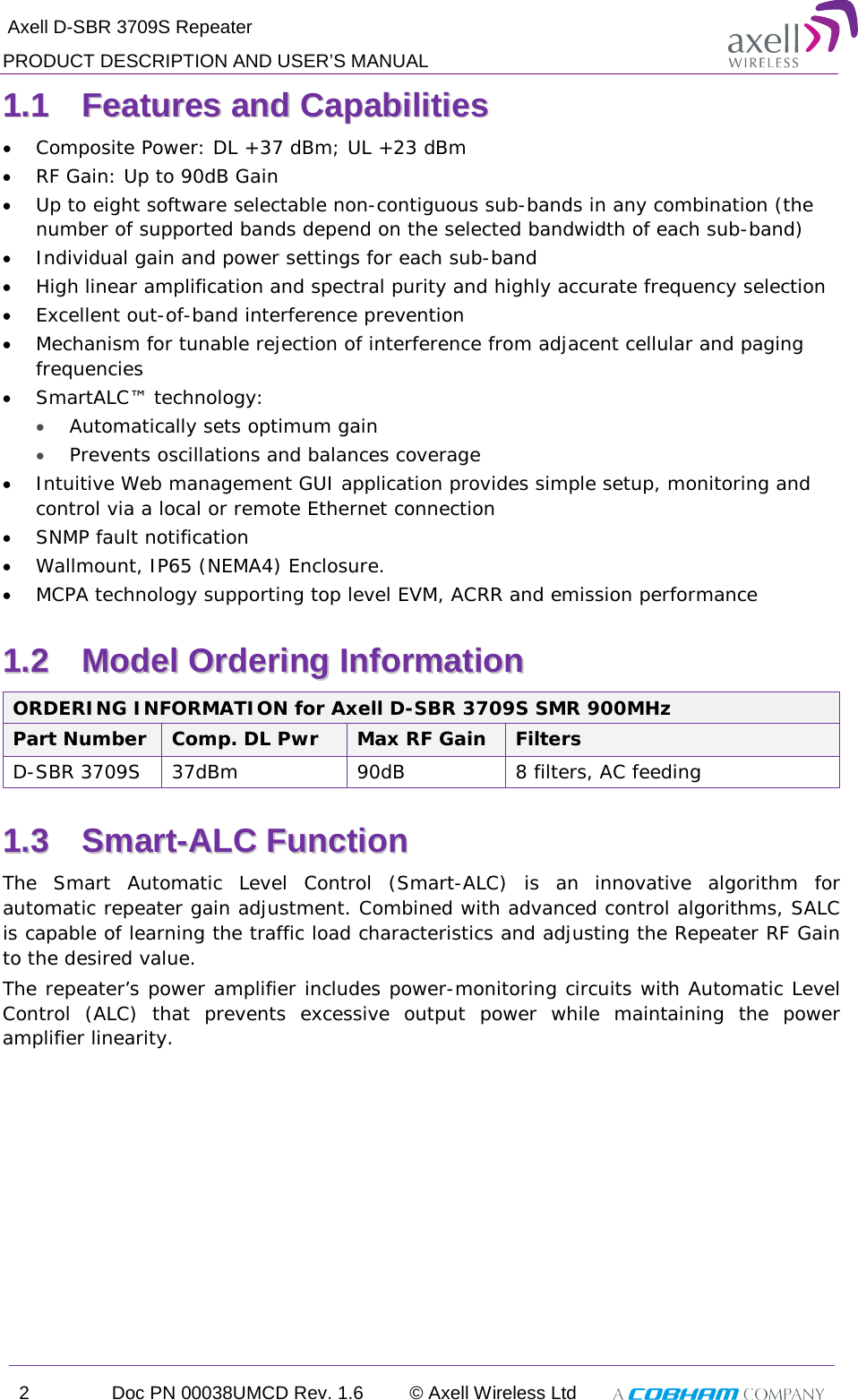
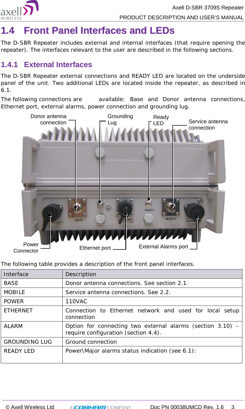
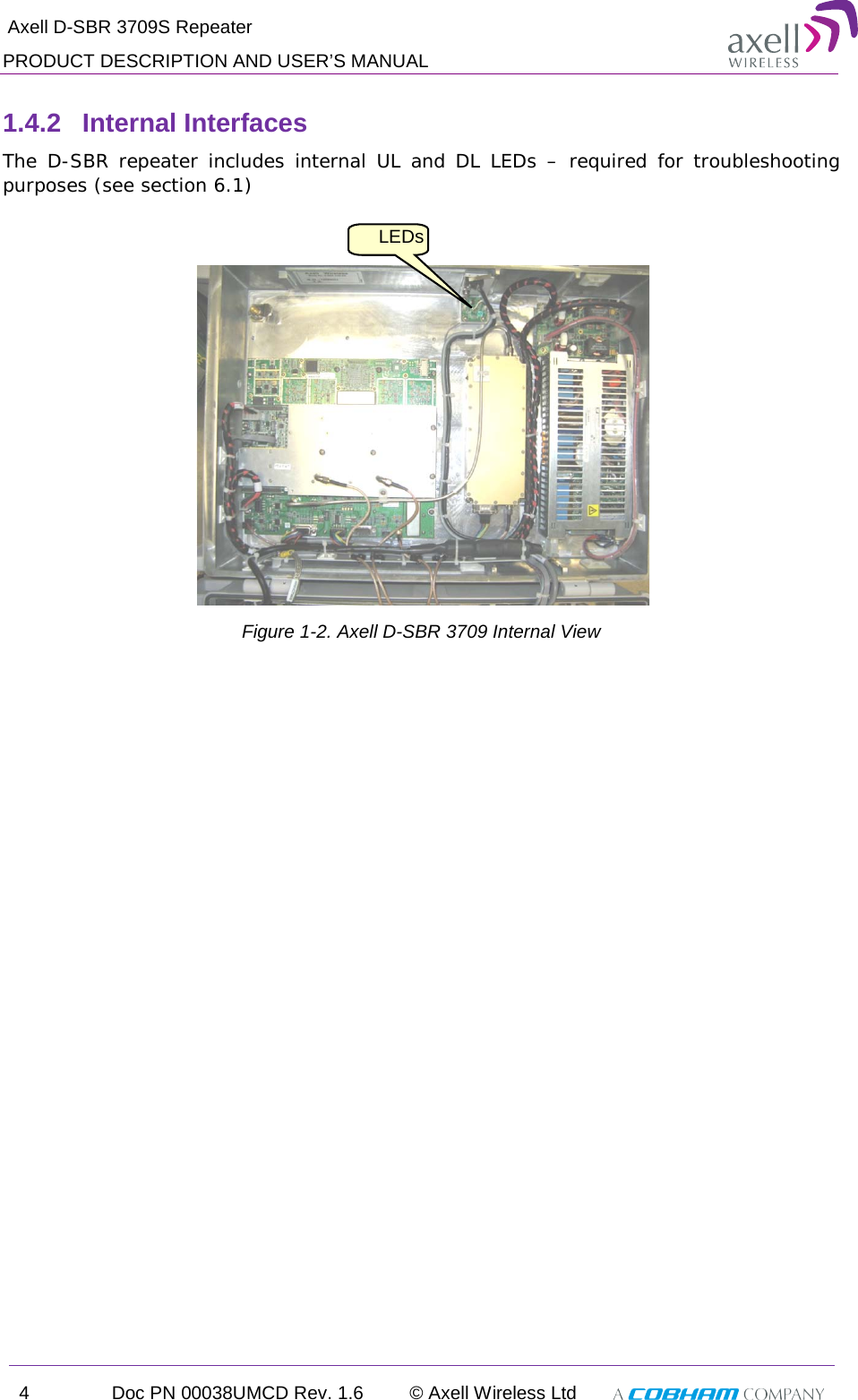
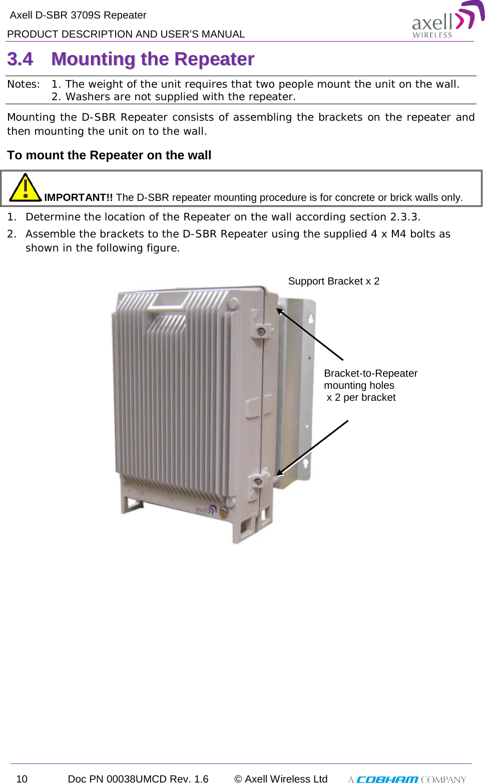
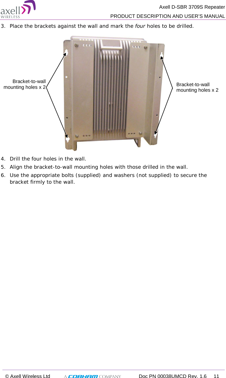
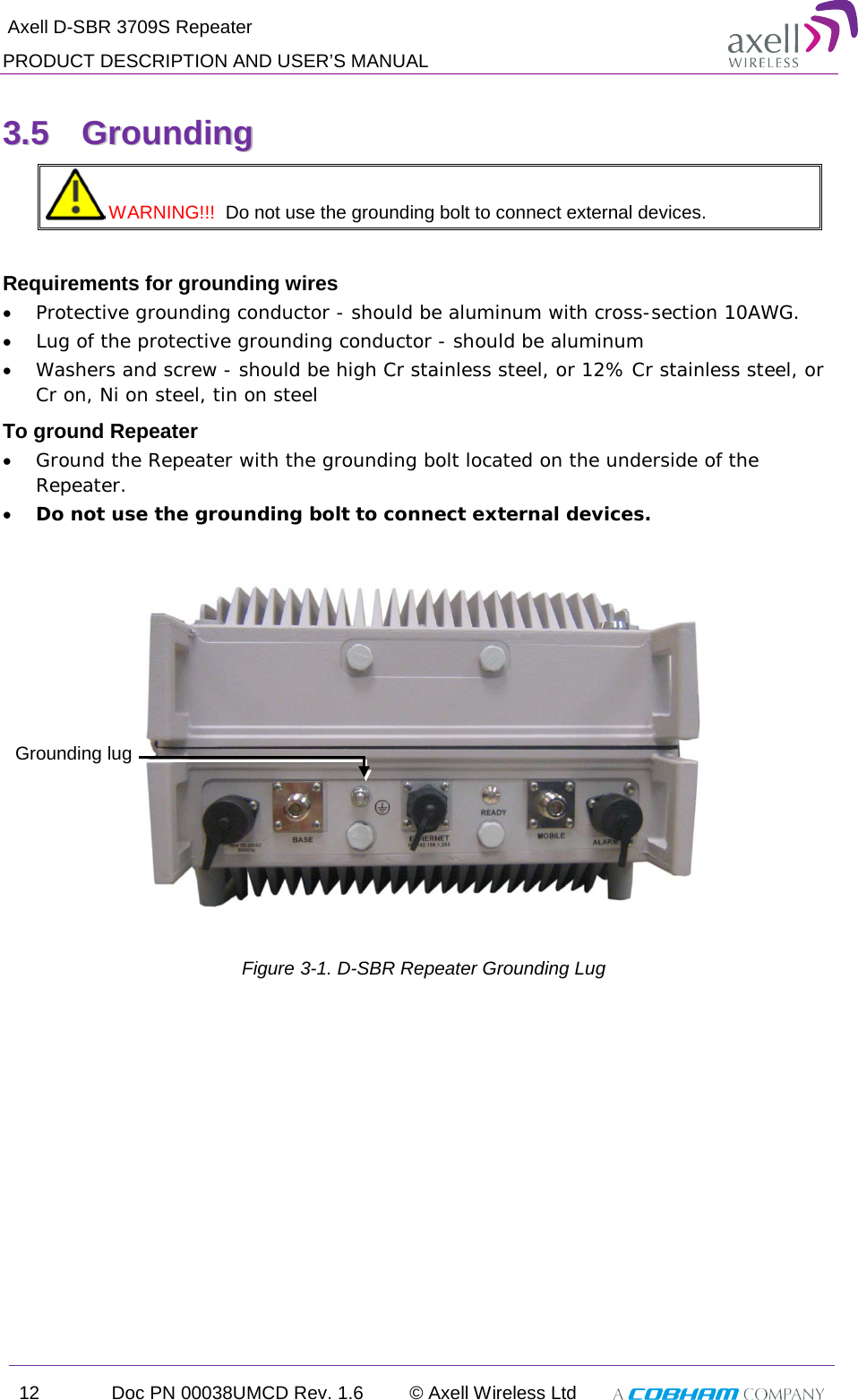
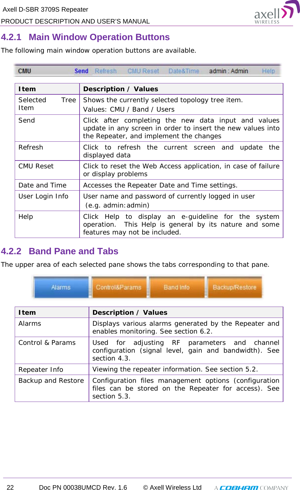
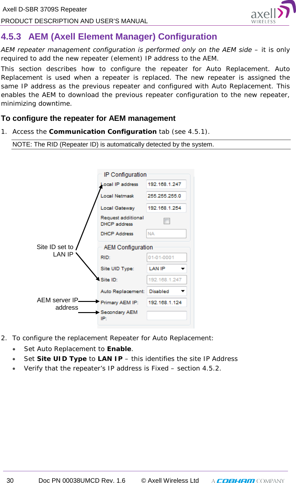
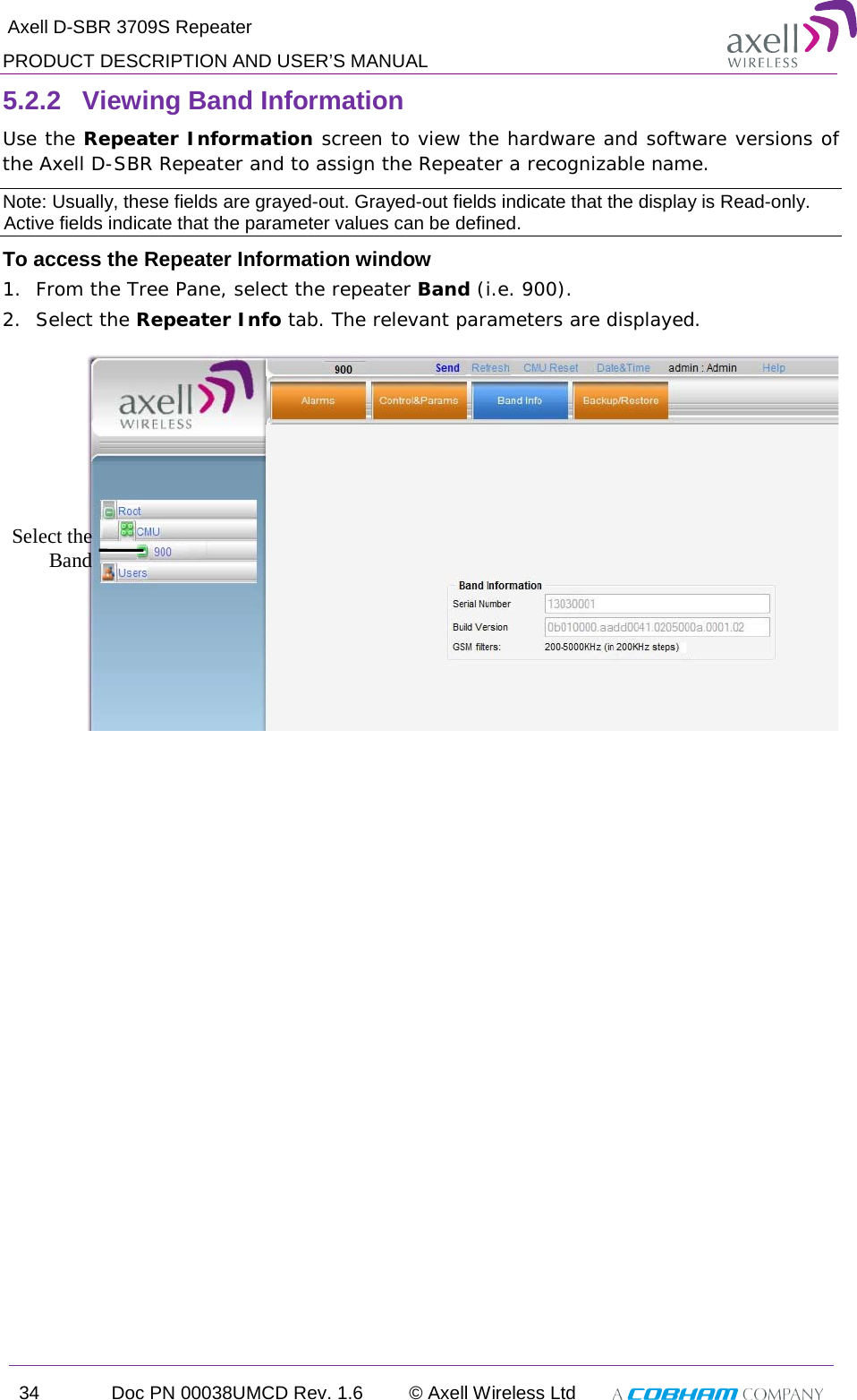
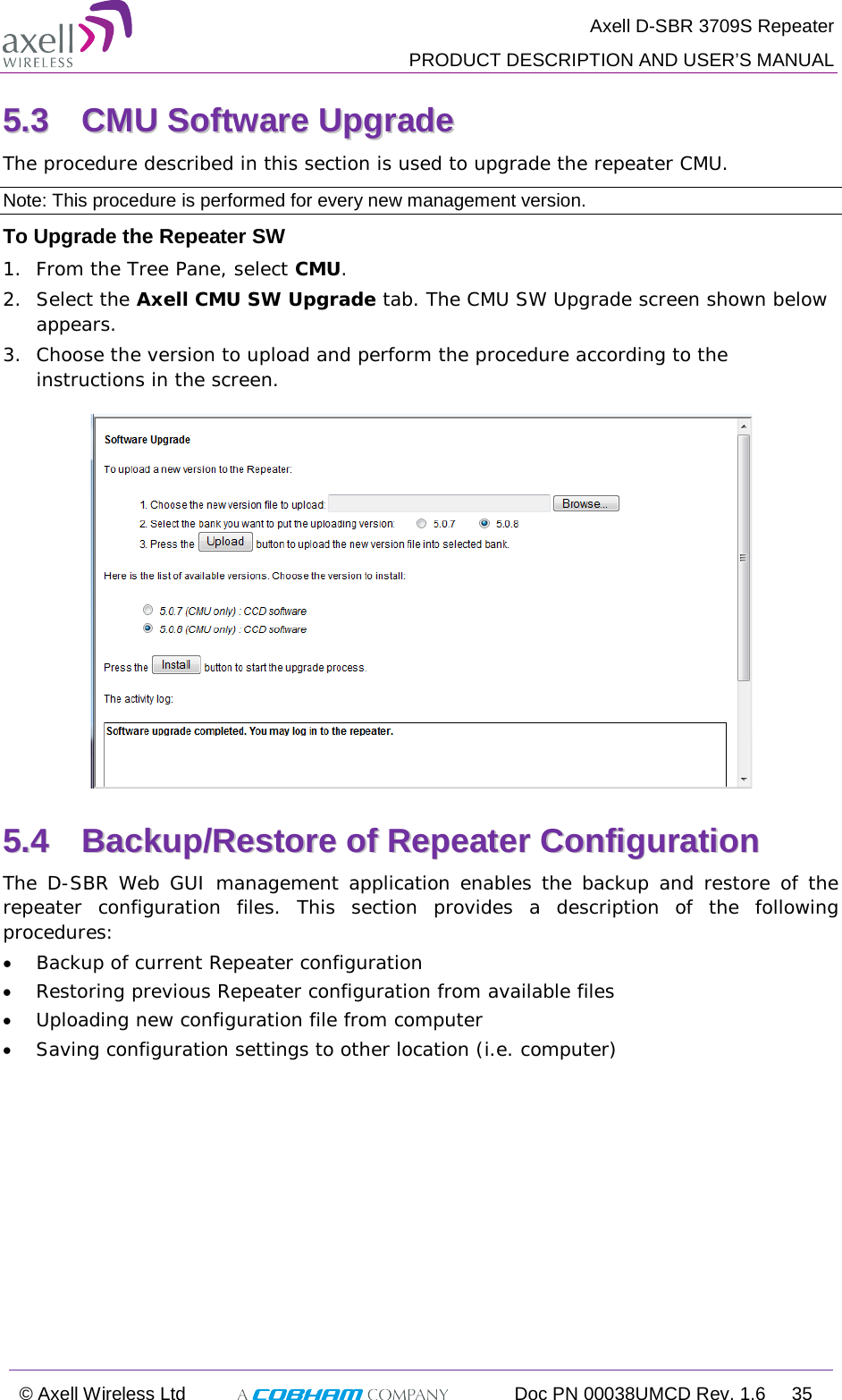
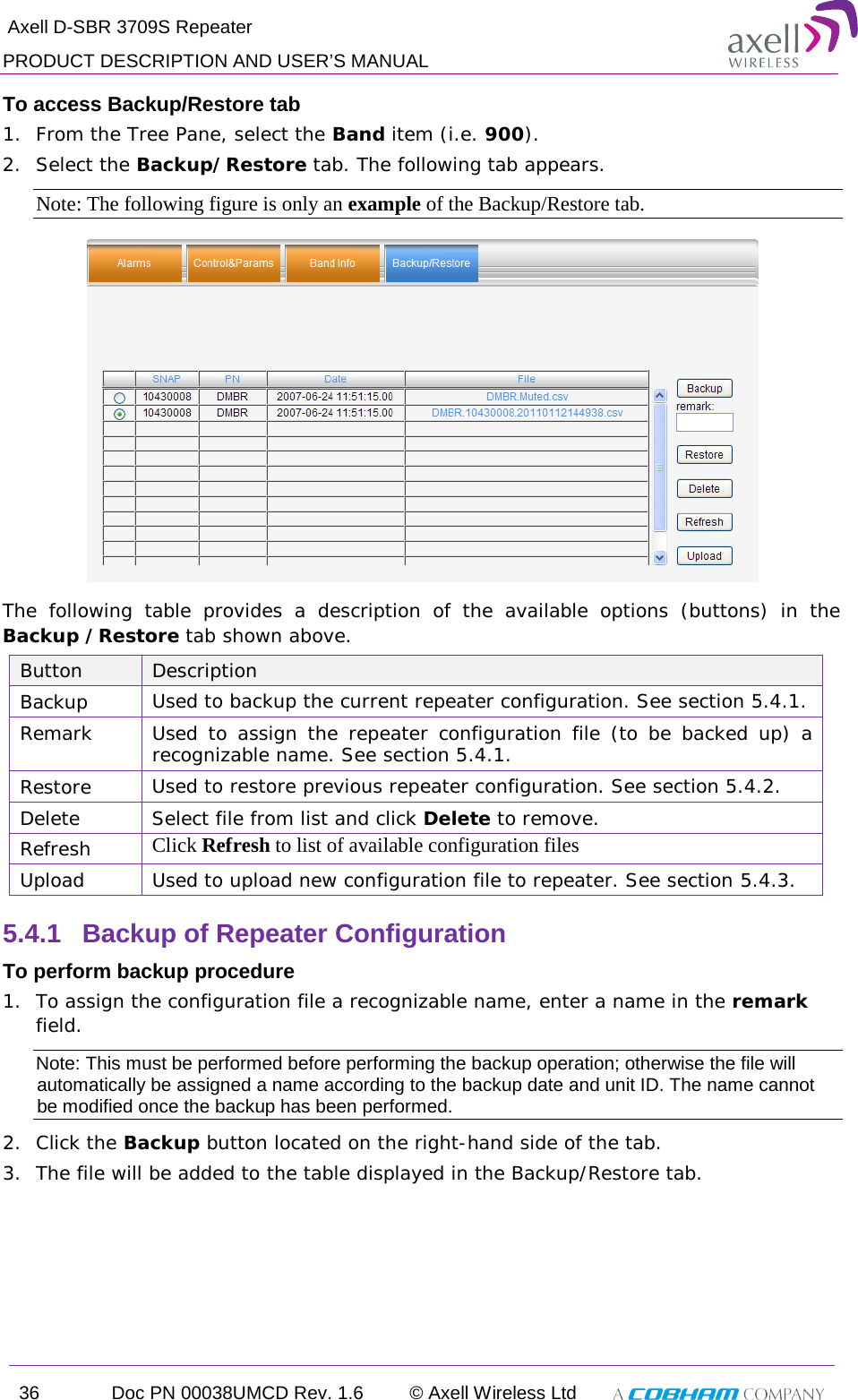
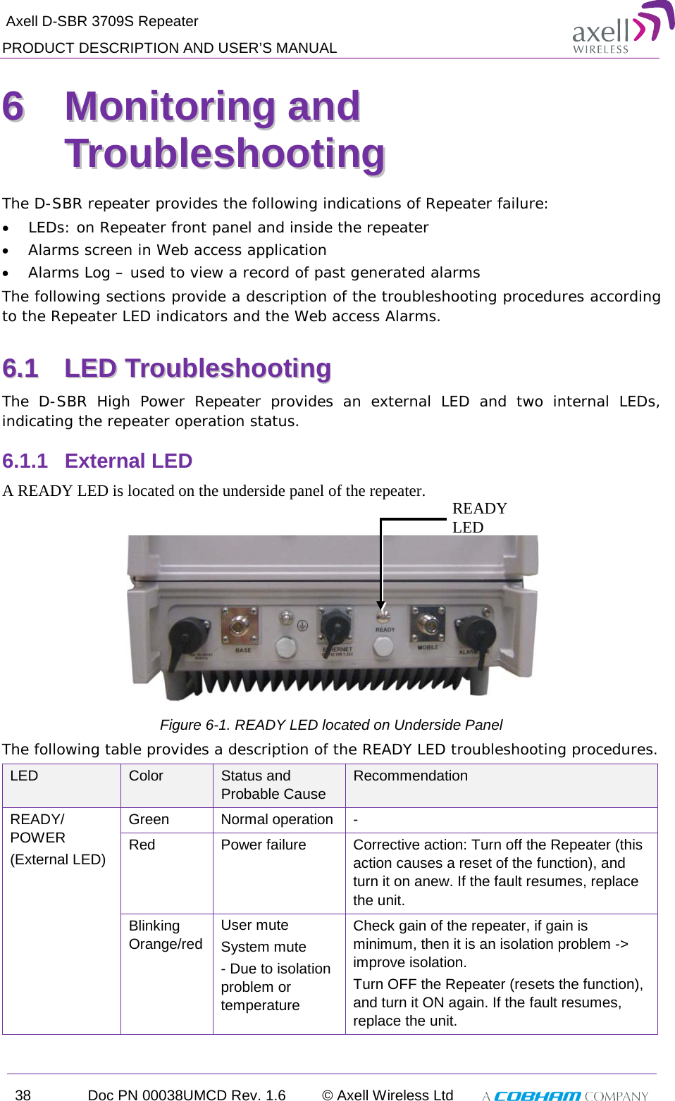
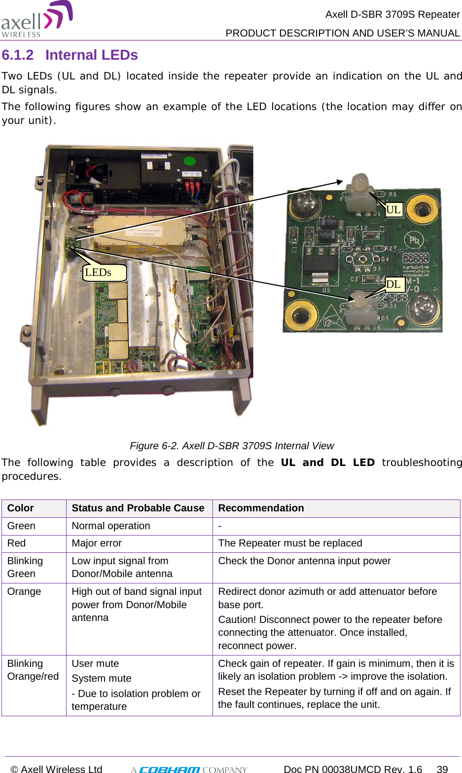
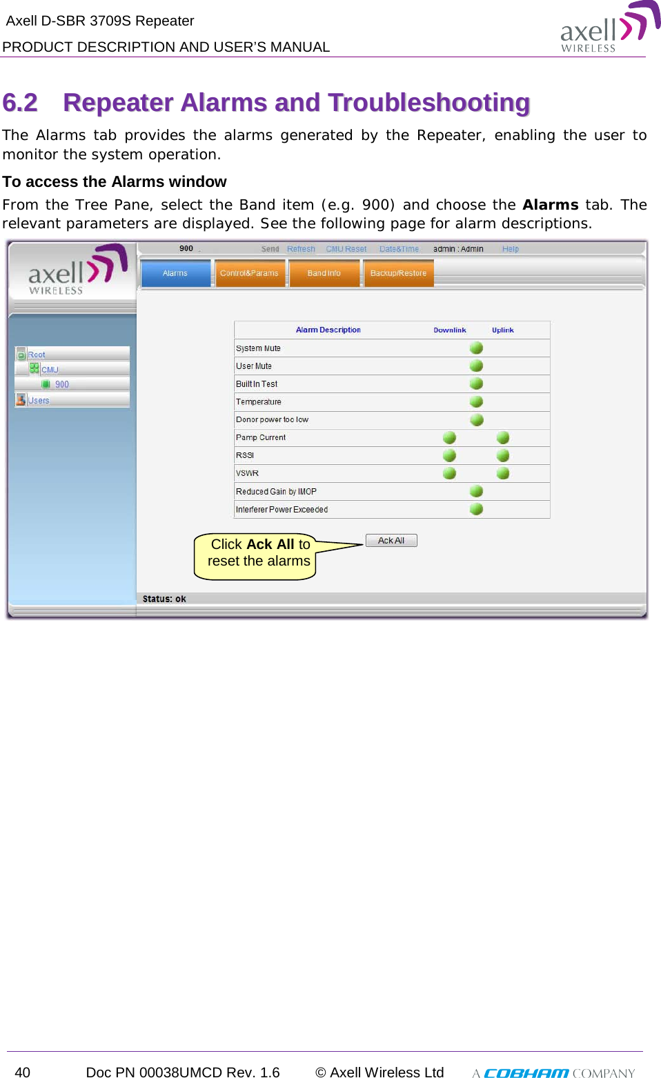
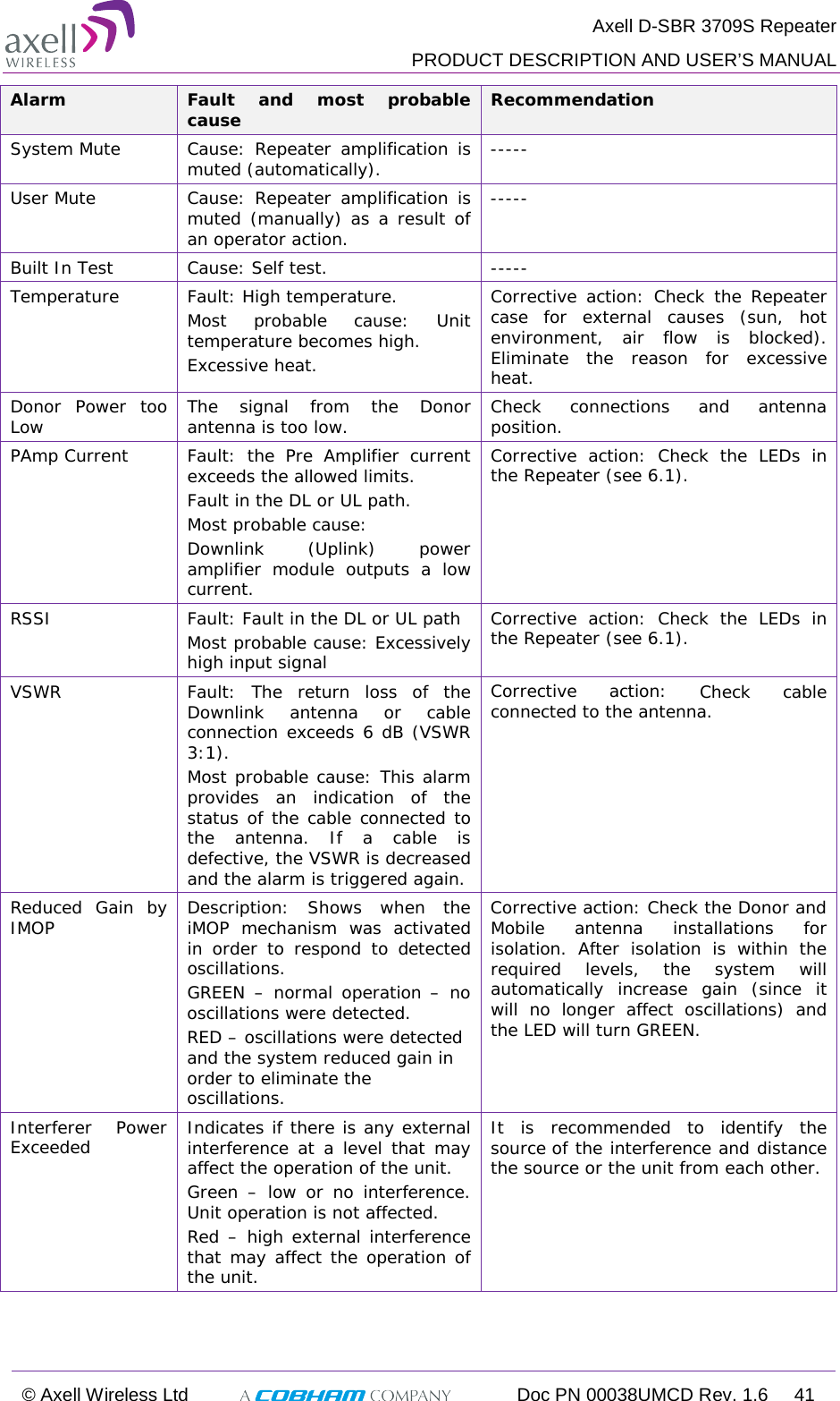
![Axell D-SBR 3709S Repeater PRODUCT DESCRIPTION AND USER’S MANUAL © Axell Wireless Ltd Doc PN 00038UMCD Rev. 1.6 9 33..33 UUnnppaacckkiinngg Upon receiving the D-SBR Repeater perform the following: 1. Examine the shipping container for damage before unpacking the unit. 2. Perform a visual inspection to reveal any physical damage to the equipment. 3. Verify that all of the equipment (listed below) is included. Otherwise contact Axell Wireless Ltd. The D-SBR Repeater is shipped with the following equipment: D-SBR single-band Repeater Ethernet RJ-45 LAN cable Ext. Alarms Cable (P/N 40WEC70500) CD with documentations Mounting Brackets Additional (supplied) installation components: Qty. Description 4x M4 bolts for mounting brackets to wall (concrete or brick only) 4x M6 screws for securing the Repeater to the brackets 1x 110VAC Power Cable 2 x Sets of keys Optional equipment AC Cable [30 ft.] – Long cable for AC power Alarm Cable [30 ft.] – Long cable for External Alarms Input](https://usermanual.wiki/PBE-Europe-as-Axell-Wireless/DSBR3709S/User-Guide-2631390-Page-19.png)