PBE Europe as Axell Wireless DSBR3709S D-SBR3709S 900 MHz Booster User Manual
Axell Wireless D-SBR3709S 900 MHz Booster
User manual
Axell D-SBR 3709S Repeater
PRODUCT DESCRIPTION AND USER’S MANUAL
Digital IP-65 Channel/Band Selective High Power
Repeater
Product Description and User’s Manual
for Axell D-SBR 3709S Repeater
Doc PN 00038UMCD Rev. 1.6
Axell D-SBR 3709S Repeater
PRODUCT DESCRIPTION AND USER’S MANUAL
II Doc PN 00038UMCD Rev. 1.6 © Axell Wireless Ltd
Copyright © 2015 Axell Wireless Ltd
All rights reserved.
No part of this document may be copied, distributed, transmitted, transcribed, stored in
a retrieval system, or translated into any human or computer language without the prior
written permission of Axell Wireless Ltd.
The manufacturer has made every effort to ensure that the instructions contained in this
document are adequate and free of errors and omissions. The manufacturer will, if
necessary, explain issues which may not be covered by this document. The
manufacturer's liability for any errors in the document is limited to the correction of
errors and the aforementioned advisory services.
This document has been prepared to be used by professional and properly trained
personnel, and the customer assumes full responsibility when using them. The
manufacturer welcomes customer comments as part of the process of continual
development and improvement of the documentation in the best way possible from the
user's viewpoint. Please submit your comments to the nearest Axell Wireless sales
representative.
Contact Information
Headquarters Axell Wireless
Aerial House, Asheridge Road
Chesham , Buckinghamshire
HP5 2QD United Kingdom
Tel: +44 1494 777000
Fax: +44 1494 777002
Commercial inquiries
info@axellwireless.com
Web site
www.axellwireless.com
Support issues
support@axellwireless.com
Technical Support Line, English speaking +44 1494 777 747
Contact information for Axell Wireless offices in other countries can be found on our web
site, www.axellwireless.com

Axell D-SBR 3709S Repeater
PRODUCT DESCRIPTION AND USER’S MANUAL
© Axell Wireless Ltd Doc PN 00038UMCD Rev. 1.6 III
About This Manual
This Product Manual provides the following information:
• Description of the Repeater
• Procedures for setup, configuration and checking the proper operation of the
Repeater
• Maintenance and troubleshooting procedures
For whom it is Intended
This Product Manual is intended for experienced technicians and engineers. It is
assumed that the customers installing, operating, and maintaining Axell Wireless
Repeaters are familiar with the basic functionality of Repeaters.
Notice
Confidential - Authorized Customer Use
This document may be used in its complete form only and is solely for the use of Axell
Wireless employees and authorized Axell Wireless channels or customers. The material
herein is proprietary to Axell Wireless. Any unauthorized reproduction, use or disclosure
of any part thereof is strictly prohibited.
All trademarks and registered trademarks are the property of their respective owners.
Disclaimer of Liability
Contents herein are current as of the date of publication. Axell Wireless reserves the
right to change the contents without prior notice. The information furnished by Axell
Wireless in this document is believed to be accurate and reliable. However, Axell
Wireless assumes no responsibility for its use. In no event shall Axell Wireless be liable
for any damage resulting from loss of data, loss of use, or loss of profits and Axell
Wireless further disclaims any and all liability for indirect, incidental, special,
consequential or other similes damages. This disclaimer of liability applies to all
products, publications and services during and after the warranty period.
Exclusive Remedies
The remedies provided herein are the Buyer’s sole and exclusive remedies. Axell
Wireless shall not be viable for any direct, incidental, or consequential damages,
whether based on contract, tort, or any legal theory.
Guarantees
• All antennas must be installed with lightning protection. Damage to power
modules, as a result of lightning are not covered by the warranty.
• Antennas must be connected before switching on AC or DC power. Switching
power on prior to the connection of antenna cables is regarded as faulty installation
procedure and therefore not covered by the Axell Wireless warranty.
• The repeater box should be closed using the two screws. The screws must be
fully tightened. Failure to do so may affect the IP65 compliancy and therefore any
warranty.

Axell D-SBR 3709S Repeater
PRODUCT DESCRIPTION AND USER’S MANUAL
IV Doc PN 00038UMCD Rev. 1.6 © Axell Wireless Ltd
Compliance with FCC
WARNING: This is NOT a CONSUMER device. This device designed for installation by
FCC LICENCEES and QUALIFIED INSTALLERS. You must have an FCC LICENCE or
express consent of an FCC Licensee to operate this device.
This is a Class B signal booster. You MUST register Class B signal boosters (as defined
in 47 CFR 90.219) online at www.fcc.gov/signal-boosters/registration.
Unauthorized use may result in significant forfeiture penalties, including penalties in
excess of $100,000 for each continuing violation.
The installation procedure must result in the signal booster complying with FCC
requirements 90.219(d). In order to meet FCC requirements 90.219(d), it may be
necessary for the installer to reduce the UL and/or DL output power for certain
installations.
FCC Part 15
This device complies with part 15 of the FCC Rules. Operation is subject to the following
two conditions:
1. This device may not cause harmful interference.
2. This device must accept any interference received, including interference that may
cause undesired operation.
If not installed and used in accordance with the instructions, this equipment generates,
uses and can radiate radio frequency energy. However, there is no guarantee that
interference will not occur in a particular installation. If this equipment does cause
harmful interference to RF reception, which can be determined by turning the equipment
off and on, the user is encouraged to try to correct the interference by one or more of
the following measures:
• Reorient or relocate the Donor antenna.
• Increase the separation between the equipment and receiver.
• Connect the equipment into an outlet on a circuit different from that to which the
receiver is connected.
Unauthorized Changes to Equipment
Changes or Modifications not expressly approved by the manufacturer responsible for
compliance could void the user’s authority to operate the equipment.
Only for in-building applications
One must be aware that FCC regulation mandate that this repeater is to be used only for
in-building applications and thus feed passive or active DAS (Distributed Antenna
Systems) accordingly.
FCC RF Exposure Limits
This unit complies with FCC RF exposure limits for an uncontrolled environment. All
antennas must be operated at a minimum distance of 35 cm between the radiator and
any person’s body.
Axell D-SBR 3709S Repeater
PRODUCT DESCRIPTION AND USER’S MANUAL
© Axell Wireless Ltd Doc PN 00038UMCD Rev. 1.6 V
Antenna Installation
Installation of an antenna must comply with the FCC RF exposure requirements. The
antenna used for this transmitter must be mounted on permanent structures.
The FCC regulation mandates that the EIRP of type B signal boosters should not exceed
5W.
Therefore the max antenna gain allowed for this type of signal booster should be limited
to the values given by equation (1) for the service antenna and equation (2) for the
donor antenna
Equation (1) - Max SERVICE antenna gain
Max SERVICE antenna gain (dBi) = 37 – (33dBi - # of antennas in dBi – cable losses in dBi).
For example:
No. of Antennas Cable Losses Max Allowed Antenna Gain
4 3 37 - (33-6-3) = 13dBi
1 3 37- (33-3) = 7dBi
10 3 37- (33-10-3) = 17dBi
Equation (2) - Max DONOR antenna gain
Max antenna gain (dBi) = 37 – (27dBi - cable losses in dBi).
Compliance with FCC deployment rule regarding the radiation of noise
Good engineering practice must be used in regard to the signal booster’s noise
radiation. Thus, the gain of the signal booster should be set so that the EIRP of the
output noise from the signal booster should not exceed the level of -43 dBm in 10 kHz
measurement bandwidth.
In the event that the noise level measured exceeds the aforementioned value, the signal
booster gain should be decreased accordingly.
In general, the ERP of noise on a spectrum more than 1 MHz outside of the pass band
should not exceed -70 dBm in a 10 kHz measurement bandwidth.
The 3709 signal booster has a noise level of -50 dBm in 10 kHz measurement at 1 MHz
spectrum outside the passband of the signal booster and an in-band noise level at
around -34 dBm in a 10 kHz bandwidth. Therefore, the noise at the antenna input port
should be calculated based on equation (3).
Equation (3) - Input Noise to SERVICE antenna
Input Noise to service antenna:
-43 dBm + Service Antenna gain – Antenna splitter losses in dBi – cable loss in dB
Example:
Signal booster connected to 10 service antennas with a 100m long ½ inch cable.
• Losses of such a cable with the connectors = ~ 11dB
• Gain = ~ 2 dBi
Assuming 10 service antennas: antenna splitter losses = 11 dB
Based on equation (3) Input antenna noise (to the antenna) = -51.1+2-11-11=-71.1 dBm
The inband input noise to the antenna should be -32+2 -11-11= -52 dbm
Axell D-SBR 3709S Repeater
PRODUCT DESCRIPTION AND USER’S MANUAL
VI Doc PN 00038UMCD Rev. 1.6 © Axell Wireless Ltd
NOTE: In this example there is no need to add an external bandpass filter to attenuate the out band
noise.
Conclusion:
Good engineering practice requires that in general when the out of band noise
measured at the service antenna input is more than -70 dbm per 10 kHz measurement
bandwidth, an external band pass filter should be added to attenuate the out of band
noise level.
General Safety Warnings Concerning Use of This System
Always observe standard safety precautions during installation, operation and
maintenance of this product.
Caution labels!
Throughout this manual, there are "Caution" warnings. "Caution"
calls attention to a procedure or practice, which, if ignored, may
result in injury or damage to the system, system component or
even the user. Do not perform any procedure preceded by a
"Caution" until the described conditions are fully understood and
met.
Danger: Electrical Shock
This equipment must be installed only indoors. To prevent
electrical shock when installing or modifying the system power
wiring, disconnect the wiring at the power source before working
with un insulated wires or terminals.
Caution: RF Exposure
RF radiation, arising from transmitter outputs connected to AWL’s
equipment, must be considered a safety hazard.
This condition might only occur in the event of cable
disconnection, or because a ‘spare’ output has been left un-
terminated. Either of these conditions would impair the system’s
efficiency. No investigation should be carried out until all RF
power sources have been removed. This would always be a wise
precaution, despite the severe mismatch between the impedance
of an N type connector at 50 ohm, and that of free space at 377
ohm, which would severely compromise the efficient radiation of
RF power. Radio frequency burns could also be a hazard, if any
RF power carrying components were to be carelessly touched!
Antenna positions should be chosen to comply with requirements
(both local & statutory) regarding exposure of personnel to RF
radiation. When connected to an antenna, the unit is capable of
producing RF field strengths, which may exceed guideline safe
values especially if used with antennas having appreciable gain.
In this regard the use of directional antennas with backscreens
and a strict site rule that personnel must remain behind the screen
while the RF power is on, is strongly recommended.
Where the equipment is used near power lines or in association
with temporary masts not having lightning protection, the use of a
safety earth connected to the case-earthing bolt is strongly
advised.
Axell D-SBR 3709S Repeater
PRODUCT DESCRIPTION AND USER’S MANUAL
© Axell Wireless Ltd Doc PN 00038UMCD Rev. 1.6 VII
Caution: Safety to personnel.
Before installing or replacing any of the equipment, the entire
manual should be read and understood.
The user needs to supply the appropriate AC or DC power to the
repeater. Incorrect power settings can damage the repeater and
may cause injury to the user.
Please be aware that the equipment may, during certain
conditions become very warm and can cause minor injuries if
handled without any protection, such as gloves
Caution: Safety to equipment
When installing, replacing or using this product, observe all safety
precautions during handling and operation. Failure to comply with
the following general safety precautions and with specific
precautions described elsewhere in this manual violates the safety
standards of the design, manufacture, and intended use of this
product.
Axell Wireless assumes no liability for the customer's failure to
comply with these precautions. This entire manual should be read
and understood before operating or maintaining the repeater.
Warning: Restricted Access
Location
Access to the Axell unit installation location is restricted to
SERVICE PERSONNEL and to USERS who have been instructed
on the restrictions and the required precautions to be taken.
Attention: Electrostatic
Sensitivity
Observe electrostatic precautionary procedures.
ESD = Electrostatic Discharge Sensitive Device.
Semiconductor transmitters and receivers provide highly reliable
performance when operated in conformity with their intended
design. However, a semiconductor may be damaged by an
electrostatic discharge inadvertently imposed by careless
handling.
Static electricity can be conducted to the semiconductor chip from
the centre pin of the RF input connector, and through the AC
connector pins. When unpacking and otherwise handling the
repeater, follow ESD precautionary procedures including use of
grounded wrist straps, grounded workbench surfaces, and
grounded floor mats.
Caution: Battery
Replacement
Risk of explosion if battery is replaced with incorrect type. Dispose
of used batteries according to instructions.

Axell D-SBR 3709S Repeater
PRODUCT DESCRIPTION AND USER’S MANUAL
VIII Doc PN 00038UMCD Rev. 1.6 © Axell Wireless Ltd
Table of Contents
1 Introduction ................................................................................................................. 1
1.1 Features and Capabilities .................................................................................................... 2
1.2 Model Ordering Information ................................................................................................ 2
1.3 Smart-ALC Function ............................................................................................................ 2
1.4 Front Panel Interfaces and LEDs ........................................................................................ 3
1.4.1 External Interfaces..................................................................................................... 3
1.4.2 Internal Interfaces ...................................................................................................... 4
2 Antenna Specifications and Installation .................................................................... 5
2.1 Base (Donor) Antenna ......................................................................................................... 5
2.1.1 Required Antenna Information .................................................................................. 5
2.1.2 Donor Antenna specifications .................................................................................... 5
2.1.3 Installation Criteria ..................................................................................................... 5
2.2 Service Antenna Requirements .......................................................................................... 6
2.2.1 Required Antenna Information .................................................................................. 6
2.2.2 Recommended Antennas .......................................................................................... 6
2.2.3 Installation Criteria ..................................................................................................... 6
2.3 Repeater Pre-Installation Requirements ............................................................................ 7
2.3.1 Safety Guidelines ...................................................................................................... 7
2.3.2 Required BTS Information ......................................................................................... 7
2.3.3 Criteria for Repeater Installation Location ................................................................. 7
2.3.4 RF Cable Installation Guidelines ............................................................................... 7
3 Installing the Repeater ................................................................................................ 8
3.1 Overview of the Installation Procedure.............................................................................. 8
3.2 Required Tools and Materials ............................................................................................. 8
3.3 Unpacking ............................................................................................................................. 9
3.4 Mounting the Repeater ...................................................................................................... 10
3.5 Grounding ........................................................................................................................... 12
3.6 Verifying Isolation between Donor and Mobile Antennas.............................................. 13
3.7 Verifying the Link between the BTS and the Repeater ................................................... 13
3.8 Antenna Connections ........................................................................................................ 14
3.9 Powering Up the Repeater ................................................................................................ 15
3.10 External Alarm Connections ............................................................................................. 16
4 Initial Setup and Commissioning ............................................................................. 17
4.1 Open a Local Web Session to the Repeater .................................................................... 18
4.1.1 Connect the Repeater to the Computer .................................................................. 18
4.1.2 Configure the Computer Network Parameters ........................................................ 18
4.1.3 Login to the Repeater .............................................................................................. 20
4.2 Navigating the Web GUI Application ................................................................................ 21
4.2.1 Main Window Operation Buttons ............................................................................. 22
4.2.2 Band Pane and Tabs ............................................................................................... 22
4.2.3 CMU Pane and Tabs ............................................................................................... 23
4.3 Signal Levels and Channel Configuration ....................................................................... 23
4.3.1 RF Gain Setting Criteria .......................................................................................... 23
4.3.2 Adjusting the Signal Levels and Configuring Channels .......................................... 24
4.3.3 Setting Date and Time ............................................................................................. 26
4.4 Configuring the External Alarms ...................................................................................... 27
4.5 Communication and System Parameters ........................................................................ 28

Axell D-SBR 3709S Repeater
PRODUCT DESCRIPTION AND USER’S MANUAL
© Axell Wireless Ltd Doc PN 00038UMCD Rev. 1.6 IX
4.5.1 The Communication Configuration Tab .................................................................. 28
4.5.2 IP Address Setup and Repeater Name ................................................................... 29
4.5.3 AEM (Axell Element Manager) Configuration ......................................................... 30
5 Administrative Operations ........................................................................................31
5.1 User Management .............................................................................................................. 31
5.1.1 User Levels .............................................................................................................. 31
5.1.2 Viewing the List of Defined Users ........................................................................... 31
5.1.3 Adding Users ........................................................................................................... 32
5.1.4 Editing a User .......................................................................................................... 32
5.1.5 Deleting a User ........................................................................................................ 33
5.2 Viewing Repeater and Band Information ......................................................................... 33
5.2.1 Viewing Repeater Level Information ....................................................................... 33
5.2.2 Viewing Band Information ....................................................................................... 34
5.3 CMU Software Upgrade ..................................................................................................... 35
5.4 Backup/Restore of Repeater Configuration .................................................................... 35
5.4.1 Backup of Repeater Configuration .......................................................................... 36
5.4.2 Restoring Previous Repeater Configuration ............................................................ 37
5.4.3 Uploading New Configuration File to Repeater ....................................................... 37
5.4.4 Saving Configuration File to Computer ................................................................... 37
6 Monitoring and Troubleshooting ..............................................................................38
6.1 LED Troubleshooting ......................................................................................................... 38
6.1.1 External LED ........................................................................................................... 38
6.1.2 Internal LEDs ........................................................................................................... 39
6.2 Repeater Alarms and Troubleshooting ............................................................................ 40
6.3 Viewing the Alarms Log .................................................................................................... 42
Appendix A: Specifications (@+25°C) ............................................................................43
Axell D-SBR 3709S Repeater
PRODUCT DESCRIPTION AND USER’S MANUAL
© Axell Wireless Ltd Doc PN 00038UMCD Rev. 1.6 1
1
1
I
In
nt
tr
ro
od
du
uc
ct
ti
io
on
n
This manual describes the Axell D-SBR 3709S IP65 High Power Digital Channel/Band
Selective Repeater. The repeater is designed for indoor installations and includes
advanced filtering capabilities to support the SMR 900MHz band for public safety and
commercial operations.
The D-SBR 3709S repeater supports up to eight non-contiguous sub-bands/channels,
where the gain and output power of each sub-band is independently tunable across the
entire band. This provides an optimal solution for operators that have a non-contiguous
spectrum.
The system supports advanced Digital Signal Processing (DSP) technology,
programmable digital filters. These capabilities enable the user to quickly and simply
customize the Repeater according to changing site requirements.
Highly linear MCPA components and unparallel innovative DSP filtering provide top level
performance that support high throughput of the latest modulation technologies such as
HSPA and LTE.
The Smart-ALC power control algorithm automatically optimizes the gain setting by
learning the actual range of RSSI levels over a user-specified period of time. The Smart-
ALC algorithm prevents oscillations, reduces the amount of isolation required by the
system and optimizes the system to minimize noise rise at the donor cell site.
Intuitive Web access monitoring and management GUI is accessible via a local or
remote Ethernet connection.
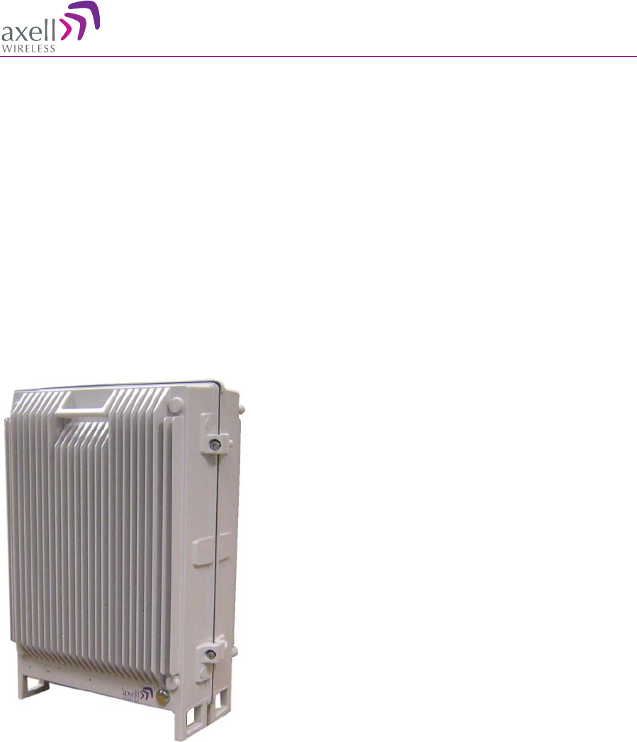
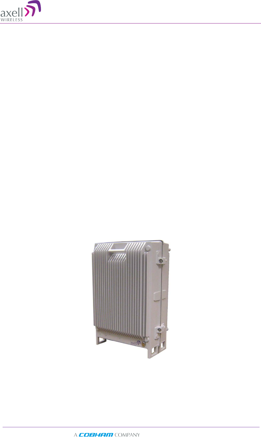
Figure 1-1. Axell D-SBR 3709S Repeater
Axell D-SBR 3709S Repeater
PRODUCT DESCRIPTION AND USER’S MANUAL
2 Doc PN 00038UMCD Rev. 1.6 © Axell Wireless Ltd
1
1.
.1
1
F
Fe
ea
at
tu
ur
re
es
s
a
an
nd
d
C
Ca
ap
pa
ab
bi
il
li
it
ti
ie
es
s
• Composite Power: DL +37 dBm; UL +23 dBm
• RF Gain: Up to 90dB Gain
• Up to eight software selectable non-contiguous sub-bands in any combination (the
number of supported bands depend on the selected bandwidth of each sub-band)
• Individual gain and power settings for each sub-band
• High linear amplification and spectral purity and highly accurate frequency selection
• Excellent out-of-band interference prevention
• Mechanism for tunable rejection of interference from adjacent cellular and paging
frequencies
• SmartALC™ technology:
• Automatically sets optimum gain
• Prevents oscillations and balances coverage
• Intuitive Web management GUI application provides simple setup, monitoring and
control via a local or remote Ethernet connection
• SNMP fault notification
• Wallmount, IP65 (NEMA4) Enclosure.
• MCPA technology supporting top level EVM, ACRR and emission performance
1
1.
.2
2
M
Mo
od
de
el
l
O
Or
rd
de
er
ri
in
ng
g
I
In
nf
fo
or
rm
ma
at
ti
io
on
n
ORDERING INFORMATION for Axell D-SBR 3709S SMR 900MHz
Part Number Comp. DL Pwr Max RF Gain Filters
D-SBR 3709S 37dBm 90dB 8 filters, AC feeding
1
1.
.3
3
S
Sm
ma
ar
rt
t-
-A
AL
LC
C
F
Fu
un
nc
ct
ti
io
on
n
The Smart Automatic Level Control (Smart-ALC) is an innovative algorithm for
automatic repeater gain adjustment. Combined with advanced control algorithms, SALC
is capable of learning the traffic load characteristics and adjusting the Repeater RF Gain
to the desired value.
The repeater’s power amplifier includes power-monitoring circuits with Automatic Level
Control (ALC) that prevents excessive output power while maintaining the power
amplifier linearity.
Axell D-SBR 3709S Repeater
PRODUCT DESCRIPTION AND USER’S MANUAL
© Axell Wireless Ltd Doc PN 00038UMCD Rev. 1.6 3
1
1.
.4
4
F
Fr
ro
on
nt
t
P
Pa
an
ne
el
l
I
In
nt
te
er
rf
fa
ac
ce
es
s
a
an
nd
d
L
LE
ED
Ds
s
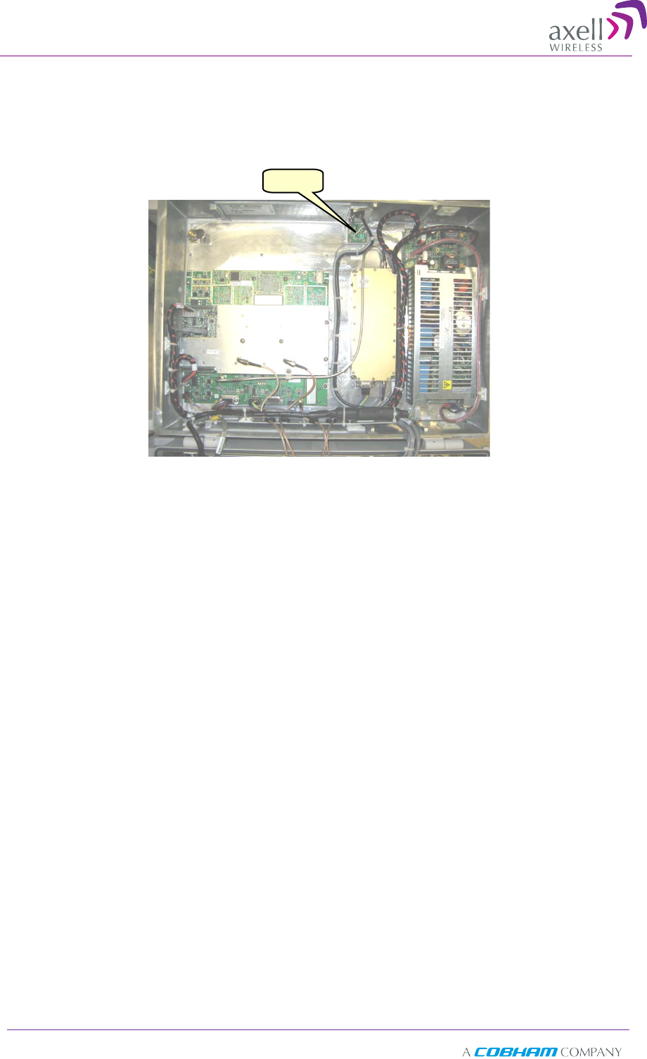
The D-SBR Repeater includes external and internal interfaces (that require opening the
repeater). The interfaces relevant to the user are described in the following sections.
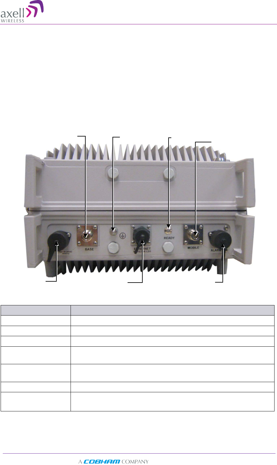
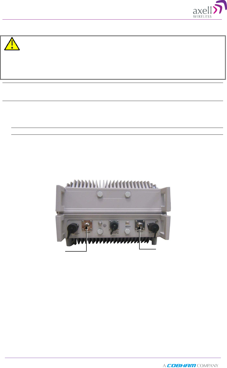
1.4.1 External Interfaces
The D-SBR Repeater external connections and READY LED are located on the underside
panel of the unit. Two additional LEDs are located inside the repeater, as described in
6.1.
The following connections are available: Base and Donor antenna connections,
Ethernet port, external alarms, power connection and grounding lug.
The following table provides a description of the front panel interfaces.
Interface Description
BASE Donor antenna connections. See section 2.1.
MOBILE Service antenna connections. See 2.2.
POWER 110VAC
ETHERNET Connection to Ethernet network and used for local setup
connection
ALARM Option for connecting two external alarms (section 3.10) –
require configuration (section 4.4).
GROUNDING LUG Ground connection
READY LED Power\Major alarms status indication (see 6.1):
Service antenna
connection
Donor antenna
connection
External Alarms port
Power
Connector
Ethernet port
Grounding
Lug Ready
LED

Axell D-SBR 3709S Repeater
PRODUCT DESCRIPTION AND USER’S MANUAL
© Axell Wireless Ltd Doc PN 00038UMCD Rev. 1.6 5
2
2
A
An
nt
te
en
nn
na
a
S
Sp
pe
ec
ci
if
fi
ic
ca
at
ti
io
on
ns
s
a
an
nd
d
I
In
ns
st
ta
al
ll
la
at
ti
io
on
n
This chapter provides information on the specifications of the donor and service
antennas suitable for operation with this repeater, and on the installation requirements
of the antennas.
2
2.
.1
1
B
Ba
as
se
e
(
(D
Do
on
no
or
r)
)
A
An
nt
te
en
nn
na
a
The Base (Donor) antenna is either a directional antenna such as a Yagi or a Panel
antenna.
2.1.1 Required Antenna Information
You will require the following antenna information:
• Antenna type and characteristics
• Height
• Length and type of coaxial cable required for connecting the Donor antenna to the
Repeater and the attenuation.
2.1.2 Donor Antenna specifications
• Max DONOR antenna gain (dBi) = 37 – (27dBi - cable losses in dBi).
• Very sharp beam pointed to the BTS.
• Minimum cable and jumper loss = 2dB.
2.1.3 Installation Criteria
Installation requirements:
• The donor antenna should point to the direction of the base station for maximum
input power.
• Install the Donor Antenna at the designated height.
• Verify that the antenna is in the base stations line of sight (raise the antenna if
necessary).
• Install the donor antenna at a higher level (i.e. higher floor) than the mobile
antenna.
• Donor antenna must be installed at a minimum distance of 35 cm from any
personnel within the area.
Axell D-SBR 3709S Repeater
PRODUCT DESCRIPTION AND USER’S MANUAL
6 Doc PN 00038UMCD Rev. 1.6 © Axell Wireless Ltd
2
2.
.2
2
S
Se
er
rv
vi
ic
ce
e
A
An
nt
te
en
nn
na
a
R
Re
eq
qu
ui
ir
re
em
me
en
nt
ts
s
WARNING!!!
• The installer is held accountable for implementing the rules required for deployment.
• Good engineering practice must be used to avoid interference.
• Output power should be reduced to solve any IMD interference issues.
2.2.1 Required Antenna Information
The following antenna requirements, specifications and site considerations should be
met:
• Type of installation – indoors only
• Service area type and size
• Antenna type and characteristics
• Height
• Length and type of coaxial cable required for connecting the antenna to the Repeater
and the attenuation.
2.2.2 Recommended Antennas
The following describes the requirements for an omni-directional mobile used for indoor
applications.
Specifications:
• One or a combination of the following antennas can be used: Ceiling Mount Patch
antenna, Wall Mount Patch antenna, Corner Reflector.
• Choose an antenna with high side lobe attenuation which enables maximum isolation
from the service/ mobile antenna.
• Maximum Antenna Gain = 37 – (33dBi – # of antennas in dBi – cable losses in dBi).
2.2.3 Installation Criteria
Determine the antenna installation configuration, according to the transmission
requirements and the installation site conditions.
Installation requirements:
• The antenna should be installed at a convenient location. It should be free of metallic
obstruction.
• Install the Service Antenna at the designated height and tune it roughly toward the
Service coverage area.
• Installation of this antenna must provide a minimum separation distance of 35 cm
from any personnel within the area.

Axell D-SBR 3709S Repeater
PRODUCT DESCRIPTION AND USER’S MANUAL
© Axell Wireless Ltd Doc PN 00038UMCD Rev. 1.6 7
2
2.
.3
3
R
Re
ep
pe
ea
at
te
er
r
P
Pr
re
e-
-I
In
ns
st
ta
al
ll
la
at
ti
io
on
n
R
Re
eq
qu
ui
ir
re
em
me
en
nt
ts
s
2.3.1 Safety Guidelines
Before installing the Repeater, review the following safety information:
• Follow all local safety regulations when installing the Repeater.
• Only qualified personnel are authorized to install and maintain the Repeater.
• Follow Electro-Static Discharge (ESD) precautions.
2.3.2 Required BTS Information
Required BTS Information
• BTS channels
• BTS output power per channel
• BTS antenna gain
• BTS antenna height
• Distance from Repeater site to BTS
2.3.3 Criteria for Repeater Installation Location
The following criteria should be considered when selecting the Repeater installation site
location:
• Application type and general surroundings
• Available installation
• Install the Repeater in a shielded, ventilated, and easy-to-reach area.
• Verify that there is a minimum of a 50 cm (20”) radius of space around the
Repeater, enabling easy access to the repeater for maintenance and on-site
inspection.
• Distance from antenna site - It is recommended that the installation location be as
close as possible to the antenna site in order to maintain the cable loss to a
minimum.
• The Repeater is convection cooled so airflow and alternation should be possible.
• Follow Electro-Static Discharge (ESD) precautions.
• Install the Repeater close to the service area to monitor the output power.
• Use low loss cables to connect the antennas to the Repeater.
2.3.4 RF Cable Installation Guidelines
• For all coaxial connections to/from the Repeater - high performance, flexible, low
loss 50 ohm coaxial communications cable.
• All cables shall be weather-resistant type.
• Cable length - determined by the Repeater installation plan. When calculating the
cable length, take into account excess cable slack so as not to limit the insertion
paths.
Axell D-SBR 3709S Repeater
PRODUCT DESCRIPTION AND USER’S MANUAL
8 Doc PN 00038UMCD Rev. 1.6 © Axell Wireless Ltd
3
3
I
In
ns
st
ta
al
ll
li
in
ng
g
t
th
he
e
R
Re
ep
pe
ea
at
te
er
r
3
3.
.1
1
O
Ov
ve
er
rv
vi
ie
ew
w
o
of
f
t
th
he
e
I
In
ns
st
ta
al
ll
la
at
ti
io
on
n
P
Pr
ro
oc
ce
ed
du
ur
re
e
NOTE: The Donor and Mobile antennas can be positioned and installed (without connection to the
Repeater) at any time either before or after mounting and grounding the Repeater.
1. Determine an appropriate location for the system according to the requirements
described in section 2.3.
2. Unpack the Repeater kit (see 3.3).
3. Assemble the brackets and mount the D-SBR Repeater on the (concrete or brick)
wall (see 3.4).
4. Ground the Repeater (see 3.5)
5. If you have not already done so, position and install the Base and Mobile antennas in
the relevant locations.
6. Before powering up the Repeater:
• Verify isolation between the donor and mobile antennas (see 3.6)
• Verify link between BTS and Base Repeater (see 3.7)
• Connect the Donor and Service antennas to the Repeater (see 3.8).
7. Power-up the Repeater (see 3.9)
IMPORTANT!! Be sure to perform the power supply connection last, otherwise
damage may be caused to the system!
8. Optional - Connect the external alarms. This can be done at any time, before or after
powering up the Repeater (see 3.10).
9. Commission the system. See Chapter 4.
Note: It is important to perform the installation procedure according to the order described above.
3
3.
.2
2
R
Re
eq
qu
ui
ir
re
ed
d
T
To
oo
ol
ls
s
a
an
nd
d
M
Ma
at
te
er
ri
ia
al
ls
s
A standard professional toolbox is required in order to mount the Repeater.
Axell D-SBR 3709S Repeater
PRODUCT DESCRIPTION AND USER’S MANUAL
© Axell Wireless Ltd Doc PN 00038UMCD Rev. 1.6 9
3
3.
.3
3
U
Un
np
pa
ac
ck
ki
in
ng
g
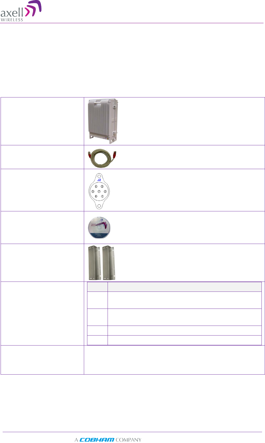
Upon receiving the D-SBR Repeater perform the following:
1. Examine the shipping container for damage before unpacking the unit.
2. Perform a visual inspection to reveal any physical damage to the equipment.
3. Verify that all of the equipment (listed below) is included. Otherwise contact Axell
Wireless Ltd. The D-SBR Repeater is shipped with the following equipment:
D-SBR single-band
Repeater
Ethernet RJ-45 LAN cable
Ext. Alarms Cable (P/N
40WEC70500)
CD with documentations
Mounting Brackets
Additional (supplied)
installation components:
Qty. Description
4x M4 bolts for mounting brackets to wall (concrete
or brick only)
4x M6 screws for
securing the Repeater to the
brackets
1x 110VAC Power Cable
2 x Sets of keys
Optional equipment AC Cable [30 ft.] – Long cable for AC power
Alarm Cable [30 ft.] – Long cable for External Alarms
Input
Axell D-SBR 3709S Repeater
PRODUCT DESCRIPTION AND USER’S MANUAL
10 Doc PN 00038UMCD Rev. 1.6 © Axell Wireless Ltd
3
3.
.4
4
M
Mo
ou
un
nt
ti
in
ng
g
t
th
he
e
R
Re
ep
pe
ea
at
te
er
r
Notes: 1. The weight of the unit requires that two people mount the unit on the wall.
2. Washers are not supplied with the repeater.
Mounting the D-SBR Repeater consists of assembling the brackets on the repeater and
then mounting the unit on to the wall.
To mount the Repeater on the wall
IMPORTANT!! The D-SBR repeater mounting procedure is for concrete or brick walls only.
1. Determine the location of the Repeater on the wall according section 2.3.3.
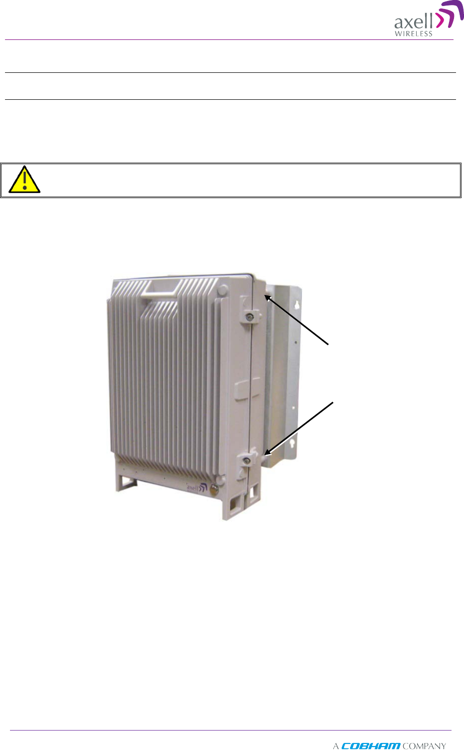
2. Assemble the brackets to the D-SBR Repeater using the supplied 4 x M4 bolts as
shown in the following figure.
Support Bracket x 2
Bracket-to-Repeater
mounting holes
x 2 per bracket
Axell D-SBR 3709S Repeater
PRODUCT DESCRIPTION AND USER’S MANUAL
© Axell Wireless Ltd Doc PN 00038UMCD Rev. 1.6 11
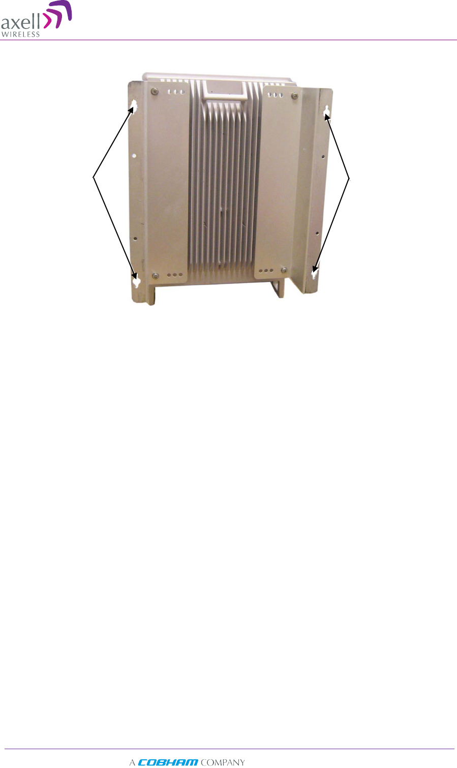
3. Place the brackets against the wall and mark the four holes to be drilled.
4. Drill the four holes in the wall.
5. Align the bracket-to-wall mounting holes with those drilled in the wall.
6. Use the appropriate bolts (supplied) and washers (not supplied) to secure the
bracket firmly to the wall.
Bracket-to-wall
mounting holes x 2
Bracket-to-wall
mounting holes x 2
Axell D-SBR 3709S Repeater
PRODUCT DESCRIPTION AND USER’S MANUAL
12 Doc PN 00038UMCD Rev. 1.6 © Axell Wireless Ltd
3
3.
.5
5
G
Gr
ro
ou
un
nd
di
in
ng
g
WARNING!!! Do not use the grounding bolt to connect external devices.
Requirements for grounding wires
• Protective grounding conductor - should be aluminum with cross-section 10AWG.
• Lug of the protective grounding conductor - should be aluminum
• Washers and screw - should be high Cr stainless steel, or 12% Cr stainless steel, or
Cr on, Ni on steel, tin on steel
To ground Repeater
• Ground the Repeater with the grounding bolt located on the underside of the
Repeater.
• Do not use the grounding bolt to connect external devices.
Figure 3-1. D-SBR Repeater Grounding Lug
Grounding lug
Axell D-SBR 3709S Repeater
PRODUCT DESCRIPTION AND USER’S MANUAL
© Axell Wireless Ltd Doc PN 00038UMCD Rev. 1.6 13
3
3.
.6
6
V
Ve
er
ri
if
fy
yi
in
ng
g
I
Is
so
ol
la
at
ti
io
on
n
b
be
et
tw
we
ee
en
n
D
Do
on
no
or
r
a
an
nd
d
M
Mo
ob
bi
il
le
e
A
An
nt
te
en
nn
na
as
s
WARNING! Perform this procedure before connecting the antennas to the Repeater or
powering on the Repeater. The Repeater should not be operated prior to the verification of the
operating parameter in its installation environment.
Before connecting the antennas or power, verify isolation between the donor and
mobile antennas
The isolation between the Base/Donor and Mobile/Service antennas is critical.
• For proper operation of the Repeater, it is recommended that the isolation between
the Donor and Service antennas be at least 12dB higher than the Repeaters set gain.
• Insure proper vertical or horizontal distance separation between Donor and Service
antennas
NOTE: Lower isolation can lead to high in-band ripple, oscillations and low signal quality.
To measure the isolation, proceed as follows:
1. Inject a known signal from a signal generator into one antenna (preferably the
Donor antenna).
2. Measure the coupled output from the Service antenna, using the Spectrum analyzer
and LNA if applicable.
3. Perform this procedure across the frequency range of both the Uplink and Downlink
bands.
4. Register the lower result for system operation.
3
3.
.7
7
V
Ve
er
ri
if
fy
yi
in
ng
g
t
th
he
e
L
Li
in
nk
k
b
be
et
tw
we
ee
en
n
t
th
he
e
B
BT
TS
S
a
an
nd
d
t
th
he
e
R
Re
ep
pe
ea
at
te
er
r
This test checks the signal strength from the BTS antenna to the Repeater.
Proceed as follows:
1. Using a Spectrum analyzer, measure the received signal from BTS at the Donor
antenna port near the Repeater.
2. Adjust the Donor antenna direction to receive the maximum signal strength.
3. Compare the received signal strength with the calculated signal strength from the
design phase.
4. In case of discrepancy, check for one of the following:
• Antenna out of direction
• Antenna tuned to side lobe instead of main lobe
• Antenna connector or antenna cable faulty
• Line-of-sight problem (obstruction), etc.
• Register the signal strength of the downlink channel for the system
operation phase.
Axell D-SBR 3709S Repeater
PRODUCT DESCRIPTION AND USER’S MANUAL
14 Doc PN 00038UMCD Rev. 1.6 © Axell Wireless Ltd
3
3.
.8
8
A
An
nt
te
en
nn
na
a
C
Co
on
nn
ne
ec
ct
ti
io
on
ns
s
CAUTION!
Do not connect the antenna cables to the Repeater before verifying the installation parameters -
specifically the isolation between the antennas.
DO NOT POWER-ON the Repeater without either the antennas being connected or the antenna
connections terminated with dummy loads.
Note: If the coaxial cables are NOT weather-resistant type, wrap the exterior coaxial cables with
insulation and holding tape (Type 3M Rubber splicing tape) for environmental protection and to
ensure longer lifetime.
To connect the antennas to the Repeater
1. Install the antenna cables along their path to the Repeater, and connect them to the
Antennas.
Note: Be sure to use low loss cables.
2. Connect the Donor antenna to the Repeater BASE port. (Donor antenna
specifications and installation criteria are described in section 2.1).
3. Connect the Service antenna to the Repeater MOBILE port. (Service antenna
specifications and installation criteria are described in section 2.2).
4. Verify all RF connectors are tightened and the cables and antennas are secured.
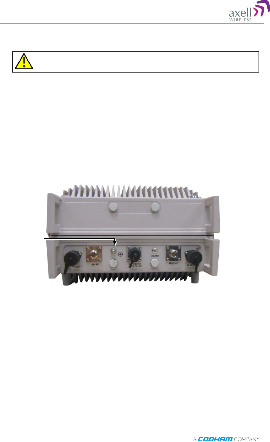
Figure 3-2. Antenna Connections
Donor antenna
connection
Service antenna
connection
Axell D-SBR 3709S Repeater
PRODUCT DESCRIPTION AND USER’S MANUAL
© Axell Wireless Ltd Doc PN 00038UMCD Rev. 1.6 15
3
3.
.9
9
P
Po
ow
we
er
ri
in
ng
g
U
Up
p
t
th
he
e
R
Re
ep
pe
ea
at
te
er
r
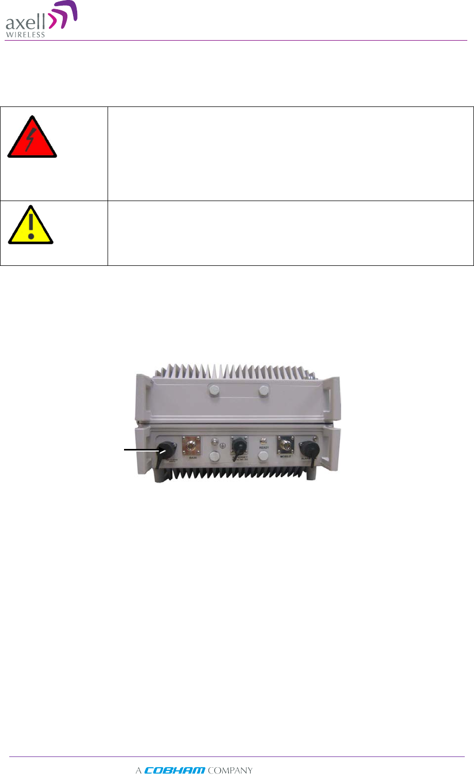
The Repeater operates from a 110 VAC power source.
WARNING!!!
Electrical Shock
This equipment must be installed indoors.
To prevent electrical
shock when installing or modifying the system power wiring,
disconnect the wiring at the power source before working with
uninsulated wires or terminals.
CAUTION!
DOUBLE POLE/NEUTRAL FUSING
To power up the repeater
1. The following slow fuse should be installed at the power outlet:
• The AC input should be supplied on a 10A dual pole circuit breaker
protected line with 3mm contact gap suitable for the end application.
2. Connect the front panel power connector to the AC power source.
AC power connector
Axell D-SBR 3709S Repeater
PRODUCT DESCRIPTION AND USER’S MANUAL
16 Doc PN 00038UMCD Rev. 1.6 © Axell Wireless Ltd
3
3.
.1
10
0
E
Ex
xt
te
er
rn
na
al
l
A
Al
la
ar
rm
m
C
Co
on
nn
ne
ec
ct
ti
io
on
ns
s
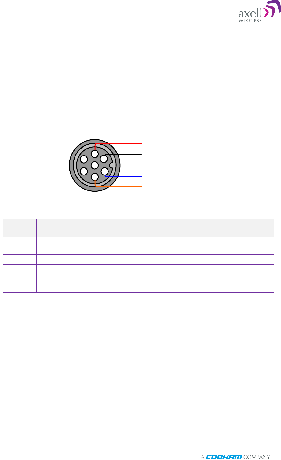
The front panel Alarm port supports two alarm connections from two external sources.
Note the following:
• The alarms can be connected any time, before or after the system is powered-on.
• The alarms cable is supplied in the product kit.
• The connections must conform to the following load restrictions: maximum
repetitive reverse voltage: 28V; Impedance load: “0” = 0V or GND; “1” = 3.8V - 28V
• After connecting, enable the External Alarms via the Web GUI CMU option, External
Alarms tab.
321
456
7
Ext. Alarm 1 (black)
Ext. Alarm 2 (red)
Ext. Alarm 1 GND (orange)
Ext. Alarm 2 GND (blue)
Alarm
The Alarm connector pinout is described below.
Wire
color Signal Pins
number Operation
Black
Ext Alarm_1
IN 1 Triggers Alarm ID 1
Orange GND 5 Ground, galvanic short to Repeater chassis.
Red
Ext Alarm_2
IN 2 Triggers Alarm ID 2
Blue GND 6 Ground, galvanic short to Repeater chassis.

Axell D-SBR 3709S Repeater
PRODUCT DESCRIPTION AND USER’S MANUAL
© Axell Wireless Ltd Doc PN 00038UMCD Rev. 1.6 17
4
4
I
In
ni
it
ti
ia
al
l
S
Se
et
tu
up
p
a
an
nd
d
C
Co
om
mm
mi
is
ss
si
io
on
ni
in
ng
g
This section provides the setup procedures for the D-SBR Repeater. The Repeater is
designed for simple plug-and-play operation, only requiring the setup of a number of
parameters (such as DL Output Power, bandwidth and Gain) via a local Web connection
and verifying that the system is operating properly.
The procedures are performed through an Ethernet connection between the Axell D-SBR
repeater and a computer.
The setup procedure consists of the following steps:
1. Open a local Web session to the Repeater (this requires configuring the
communication parameters of the computer used), see 4.1.
If you are not familiar with the Axell Web Access application, it is recommended to
quickly review the Navigating the Web GUI Application section (see 4.2).
2. Adjust the signal levels and configuring the sub-bands (see 4.3).
3. After the required coverage is attained for the location, verify that no Alarms are
generated before connecting to the main control center.
4. Set the Repeater time and date (see 4.3.3).
5. If external alarms are connected - configure the external alarms (see 4.4).
Axell D-SBR 3709S Repeater
PRODUCT DESCRIPTION AND USER’S MANUAL
18 Doc PN 00038UMCD Rev. 1.6 © Axell Wireless Ltd
4
4.
.1
1
O
Op
pe
en
n
a
a
L
Lo
oc
ca
al
l
W
We
eb
b
S
Se
es
ss
si
io
on
n
t
to
o
t
th
he
e
R
Re
ep
pe
ea
at
te
er
r
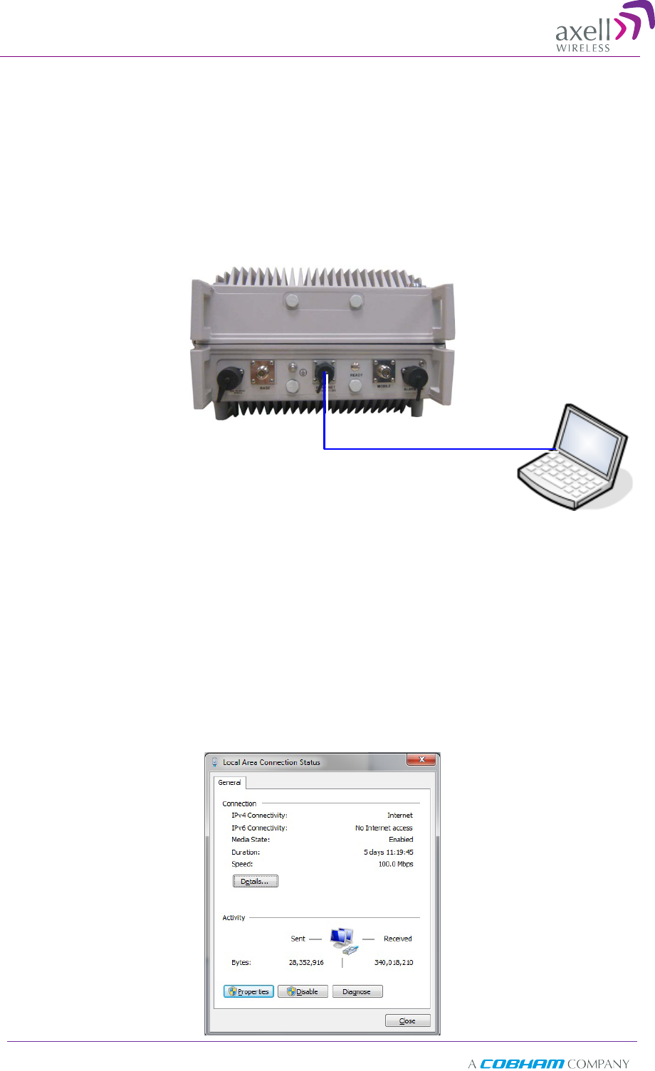
4.1.1 Connect the Repeater to the Computer
To connect Repeater to Computer
Interconnect the computer and the Repeaters’ front panel Ethernet ports with the
supplied cable as shown below.
4.1.2 Configure the Computer Network Parameters
Configure the computer network parameters to communicate with the Repeater. Note
that the procedure may vary slightly depending on the operating system installed on
your computer. The following procedure is for MS Windows 7.
To configure the computer’s network parameters:
1. Click the Start menu and choose Control Panel.
2. In the Control Panel, click Network and Internet.
3. Click Network and Sharing Center and then click Local Area Connection.
The Local Area Connections Status dialog appears with the General tab displayed
by default.
Ethernet cable
Axell D-SBR Repeater
Axell D-SBR 3709S Repeater
PRODUCT DESCRIPTION AND USER’S MANUAL
© Axell Wireless Ltd Doc PN 00038UMCD Rev. 1.6 19
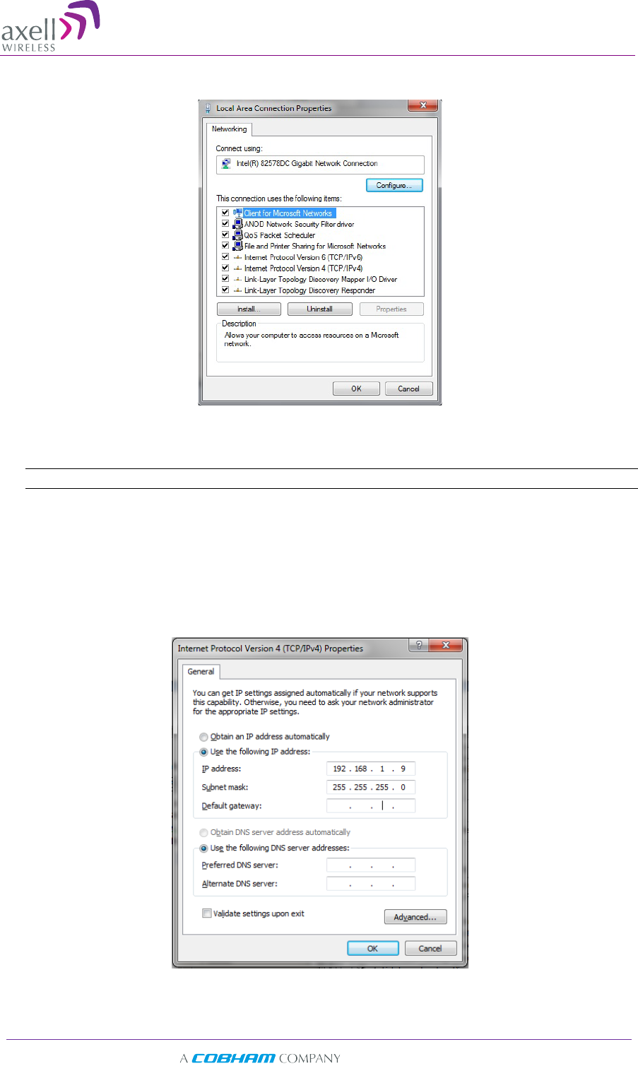
4. Click the Properties button. The Networking tab appears.
5. In the Items list, double-click the “Internet Protocol Version 4 (TCP*IPv4)” item.
6. The Internet Protocol Version 4 (TCP/IPv4) Properties dialog appears.
Note: The Repeater is supplied with the default IP address 192.168.1.253.
7. Assign your computer an IP address in the same subnet, in order to communicate
with the unit.
• In the IP address area:
• Enter the IP address 192.168.1.x, where ‘x’ can be any number between 2
and 250 inclusive. For example, (192.168.1.9)
• Define the subnet mask as shown (255.255.255.0)
• Click OK. The computer communication parameters are now defined and
you can open a session to the Repeater.
Axell D-SBR 3709S Repeater
PRODUCT DESCRIPTION AND USER’S MANUAL
20 Doc PN 00038UMCD Rev. 1.6 © Axell Wireless Ltd
4.1.3 Login to the Repeater
NOTE: The Repeater is factory assigned the address 192.168.1.253. Initial login is performed using
this address; however it is recommended to make the necessary modifications according to
information provided by your network administrator.
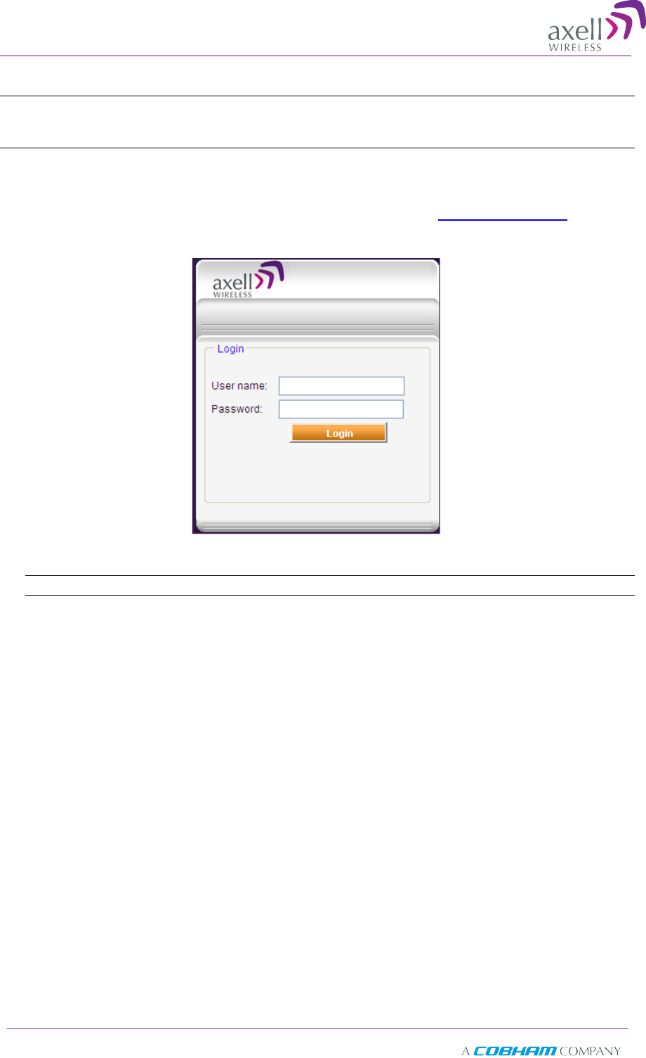
To login to the Repeater
1. Open a standard Flash-enabled browser (e.g. IE or Firefox).
2. In the address line, enter the IP address of the Repeater. http://192.168.1.253. A
session will be established with the Repeater an the login dialog appears.
3. Type the default User Name admin and the default Password admin.
Note that both are case sensitive and must be entered with lower case letters.
4. Click Login. The application main window appears.
5. Quickly review the following section describing the application window and then
proceed to configure the signal levels according to section 4.3.2.
Axell D-SBR 3709S Repeater
PRODUCT DESCRIPTION AND USER’S MANUAL
© Axell Wireless Ltd Doc PN 00038UMCD Rev. 1.6 21
4
4.
.2
2
N
Na
av
vi
ig
ga
at
ti
in
ng
g
t
th
he
e
W
We
eb
b
G
GU
UI
I
A
Ap
pp
pl
li
ic
ca
at
ti
io
on
n
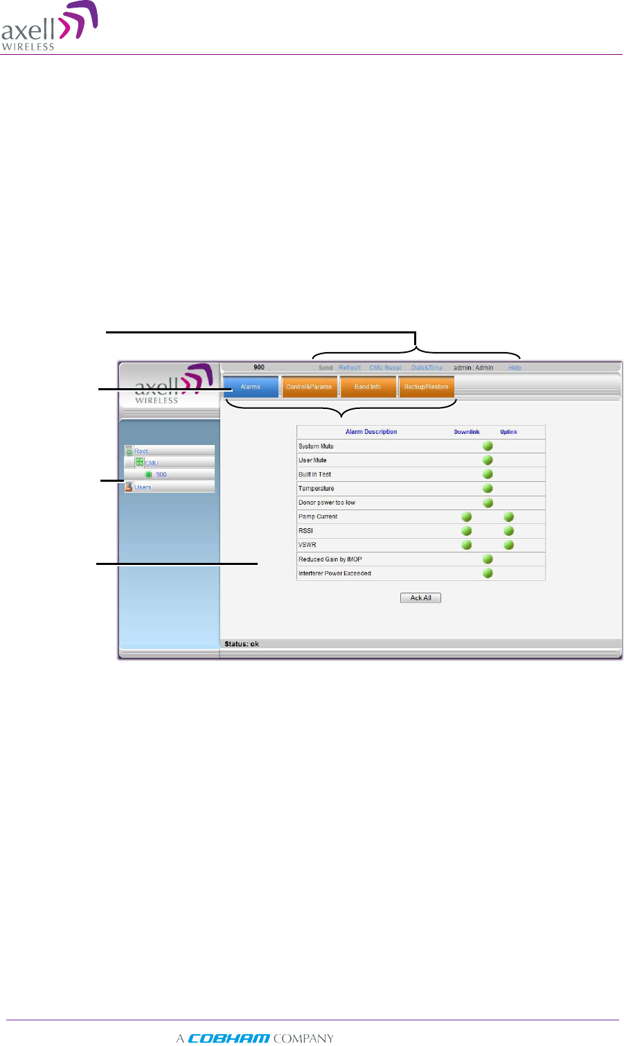
This section describes how to navigate the Web Management application. The Web
Access interface provides three groups of options, listed in the left side Topology Tree
items:
• CMU – Communication parameters, dry-contact alarm configuration and software
upgrade options. configuration, software download and upload and and
communication parameter settings.
• 900 – RF parameters, monitoring and backup and restore options.
• Admin – User definition and management options and enables changing user
passwords.
Topology Tree
Items
Pane related to
selected tree
item
Operation
Buttons
Tabs related to
selected Tree
item
Axell D-SBR 3709S Repeater
PRODUCT DESCRIPTION AND USER’S MANUAL
22 Doc PN 00038UMCD Rev. 1.6 © Axell Wireless Ltd
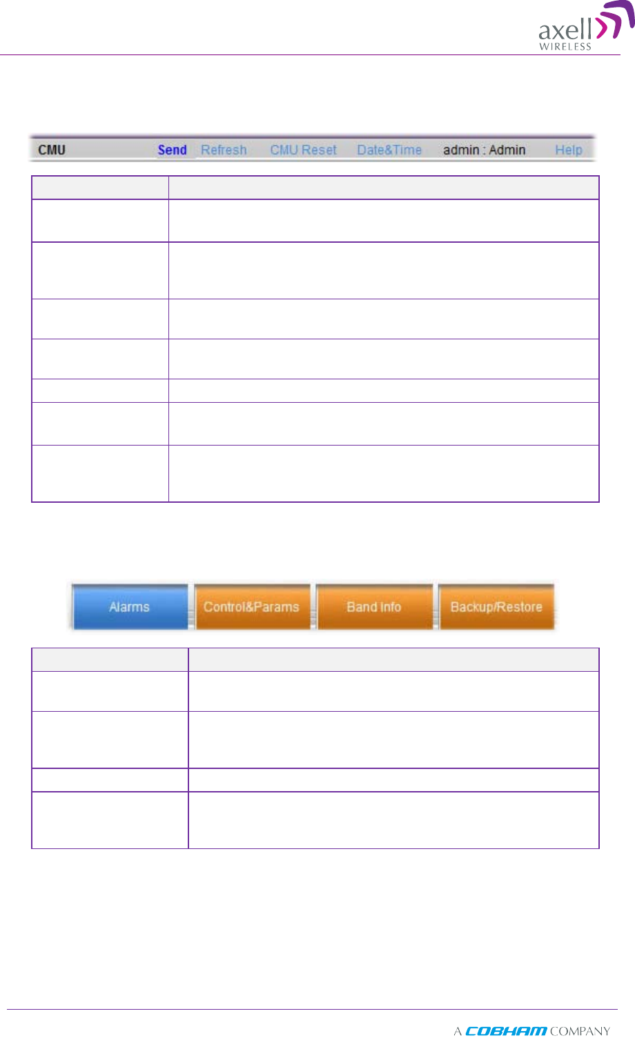
4.2.1 Main Window Operation Buttons
The following main window operation buttons are available.
Item Description / Values
Selected Tree
Item Shows the currently selected topology tree item.
Values: CMU / Band / Users
Send
Click after completing the new data input and values
update in any screen in order to insert the new values into
the Repeater, and implement the changes
Refresh
Click to refresh the current screen and update the
displayed data
CMU Reset Click to reset the Web Access application, in case of failure
or display problems
Date and Time Accesses the Repeater Date and Time settings.
User Login Info User name and password of currently logged in user
(e.g. admin:admin)
Help Click Help to display an e-guide
line for the system
operation. This Help is general by its nature and some
features may not be included.
4.2.2 Band Pane and Tabs
The upper area of each selected pane shows the tabs corresponding to that pane.
Item Description / Values
Alarms Displays various alarms generated by the Repeater and
enables monitoring. See section 6.2.
Control & Params
Used for adjusting RF parameters and channel
configuration (signal level, gain and bandwidth). See
section 4.3.
Repeater Info Viewing the repeater information. See section 5.2.
Backup and Restore
Configuration files management options (configuration
files can be stored on the Repeater for access). See
section 5.3.
Axell D-SBR 3709S Repeater
PRODUCT DESCRIPTION AND USER’S MANUAL
© Axell Wireless Ltd Doc PN 00038UMCD Rev. 1.6 23
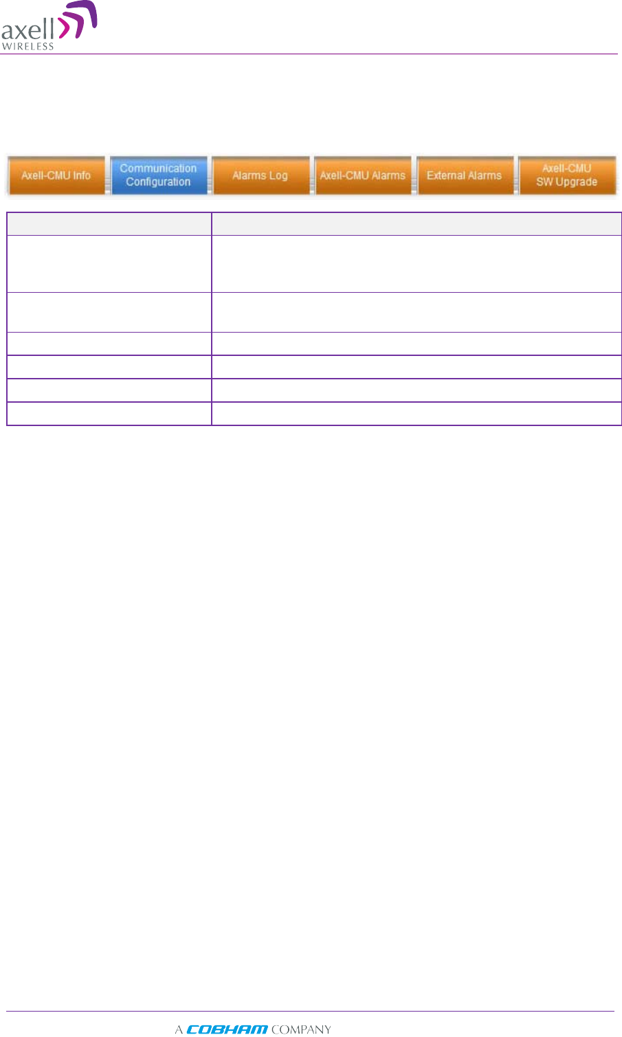
4.2.3 CMU Pane and Tabs
When the CMU item is selected in the Topology Tree, the following menu items are
available.
Item Description / Values
Axell CMU Info Shows Repeater level information such as SW and HW
versions and identification number. In addition, enables
setting minimum alarm levels (see 5.2.1).
Communication
Configuration Used to set IP, SNMP and other communication
parameters
Alarms Log Log of past and current alarms (see 6.3).
Axell-CMU Alarms Shows any external alarms that were generated.
External Alarms Used to define any connected external alarms (see 4.4)
Axell-CMU SW Upgrade Options for CMU software upgrade (see 5.3).
4
4.
.3
3
S
Si
ig
gn
na
al
l
L
Le
ev
ve
el
ls
s
a
an
nd
d
C
Ch
ha
an
nn
ne
el
l
C
Co
on
nf
fi
ig
gu
ur
ra
at
ti
io
on
n
This section provides a description of the RF Gain setting criteria (set via the Controls
and Params Pane), a full description of the Control and Params pane, and a step-by-step
procedure of the signal level and channel configuration procedure.
4.3.1 RF Gain Setting Criteria
The gain range is up to 90dB and is set by default to its maximum value. The defined
gain will be optimized by the SALC mechanism.
Axell D-SBR 3709S Repeater
PRODUCT DESCRIPTION AND USER’S MANUAL
24 Doc PN 00038UMCD Rev. 1.6 © Axell Wireless Ltd
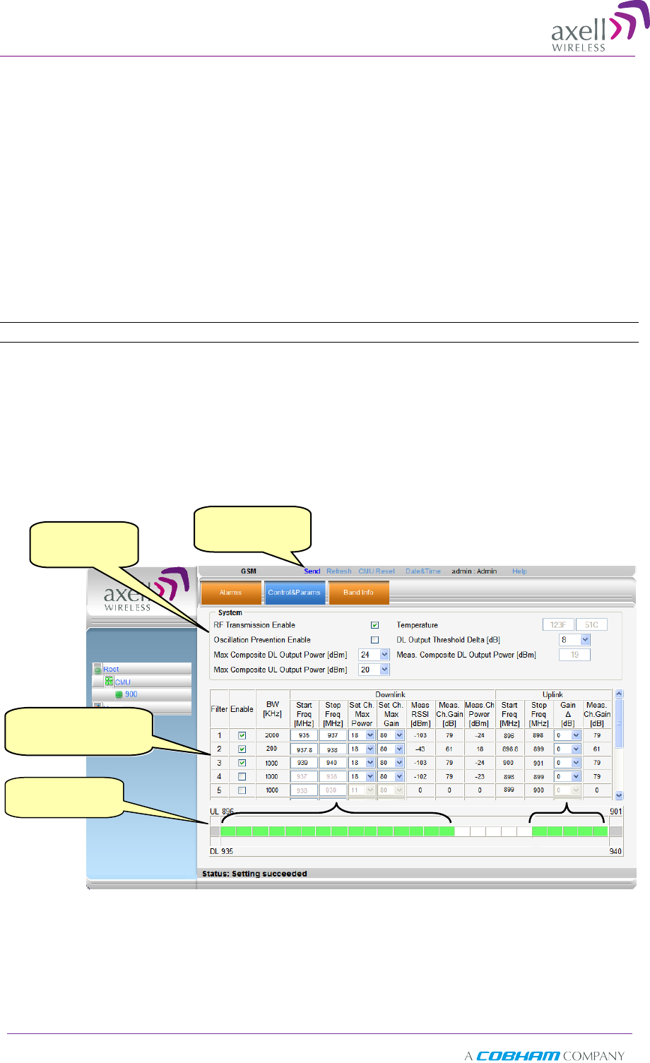
4.3.2 Adjusting the Signal Levels and Configuring Channels
The Control and Params (parameters) window is used to configure each of the
supported band's sub-bands and Max UL/DL Power. This section describes each of the
fields.
Each sub-band is individually defined by setting the following:
• Bandwidth (start and stop frequency)
• Maximum power
• Maximum gain
• Gain delta (used for noise control)
The defined sub-bands are displayed in the lower part of the screen for reference.
To adjust the signal levels and configure the channels
Note: Be sure to click Send with each change.
1. In the topology tree, click Root, then click CMU and then click the repeater Band.
2. Click the Control and Params tab. The corresponding pane appears.
The window is divided into the following areas:
• System – overall parameters for the service.
• Sub-band (filter) definitions – used to define up to eight sub-bands and
their RF parameters.
• Sub-bands view – graphical display of defined sub-bands for the service.
3. Set the System Level parameters:
• Verify that the RF Transmission Enable parameter is checked.
• Set the Max Composite DL Output Power according to your site
requirements and click Send. The Measured Composite DL Output Power is
displayed in the adjacent field.
System
level
parameters
Click Send with
each change
Sub-band definition
options
Defined
band channels

Axell D-SBR 3709S Repeater
PRODUCT DESCRIPTION AND USER’S MANUAL
© Axell Wireless Ltd Doc PN 00038UMCD Rev. 1.6 25
If the composite output power exceeds the defined value, the Smart ALC
feature begins working.
• Set the Max Composite UL Output Power according to your site
requirements.
Additional parameters (not required for initial setup) are:
• Oscillation Prevention Enable - Enables oscillation detection mechanism
that maintains repeater functionality.
• Temperature - Displays Repeater ambient temperature.
• DL Output Threshold Delta (dB) - the delta from the set Composite Output
Power, below which the alarm 'Donor power is too low' is activated.
For example, if the DL Output Threshold value is set to 8dB, when the
Measured Composite DL output power is 8dB less than the set Composite
Output Power, an alarm is generated.
• Meas. Composite DL Output Power – displays the currently measured
output signal level.
4. To configure each sub-band:
• Checkmark Enable. The configuration parameters in that row will be
available.
• In the Downlink area, set the Start and Stop DL Frequency (MHz). (The
Uplink Start and Stop frequencies will be automatically allocated.)
The defined BW will be displayed in the BW KHz column (to the left of the
Start Frequency).
Be sure to choose Start/Stop values displayed in the Band Info tab.
• Set the (Downlink) Max Gain as follows: by default, the MAX Gain (DL)
parameter is set to its highest level (90dB). Change the Channel Max
Gain (DL) according to the measured/calculated input power and isolation
measurements.
• The recommended Maximum Gain setting is approximately 12 dB less than
the isolation between the service and donor antennas.
5. If the site NOISE LEVEL is high enough to cause interference, adjust the noise level
as follows:
• Adjust the Gain Delta parameter – this sets the delta between the uplink
and downlink gain (so the uplink gain is relatively lower than the downlink
gain.
• Click Send.
• Repeat the procedure until the desired coverage is achieved.
6. More information on parameters for the selected sub-band:
• DL Set Ch. Max. Gain Sets the power for the antennas. The value is about
15 dB less than the isolation between the donor antenna and the mobile
antenna.
The Value defined in the DL path is reflected in the UL path, however to
define different UL and DL path values the Gain Delta parameter is used and
its defined value is added to the UL value.
• DL Measured RSSI - measured DL signal.
• DL Measured Ch. Gain - measured DL Gain (dB) for the selected sub-
band.
• DL Measured Ch. Power - measured Power (dBm) for the selected sub-
band.
Axell D-SBR 3709S Repeater
PRODUCT DESCRIPTION AND USER’S MANUAL
26 Doc PN 00038UMCD Rev. 1.6 © Axell Wireless Ltd
• UL Gain Δ - used for noise control. Sets the difference between UL and DL
gain.
• UL Measured Ch. Gain - measured UL Gain (dB) for the selected sub-
band.
7. Click Send (top window area option).
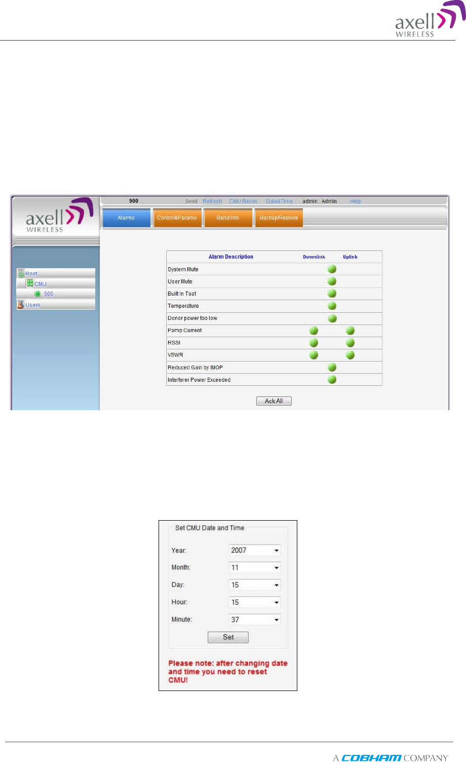
8. After the channels have been configured and the required coverage is attained for
the location, verify that no Alarms are generated:
• Click the Alarms tab
• Verify that all the indicators are GREEN in the Alarms tab.
4.3.3 Setting Date and Time
It is important to set the correct date and time on the unit since this provides the
timestamp for each logged event and alarm.
To set the Repeaters date and time
1. Click on CMU in the tree pane, click on Date & Time in the menu bar.
2. Set the date and time parameters and click on Set.
3. Click Reset CMU at the top of the Main window.
Axell D-SBR 3709S Repeater
PRODUCT DESCRIPTION AND USER’S MANUAL
© Axell Wireless Ltd Doc PN 00038UMCD Rev. 1.6 27
4
4.
.4
4
C
Co
on
nf
fi
ig
gu
ur
ri
in
ng
g
t
th
he
e
E
Ex
xt
te
er
rn
na
al
l
A
Al
la
ar
rm
ms
s
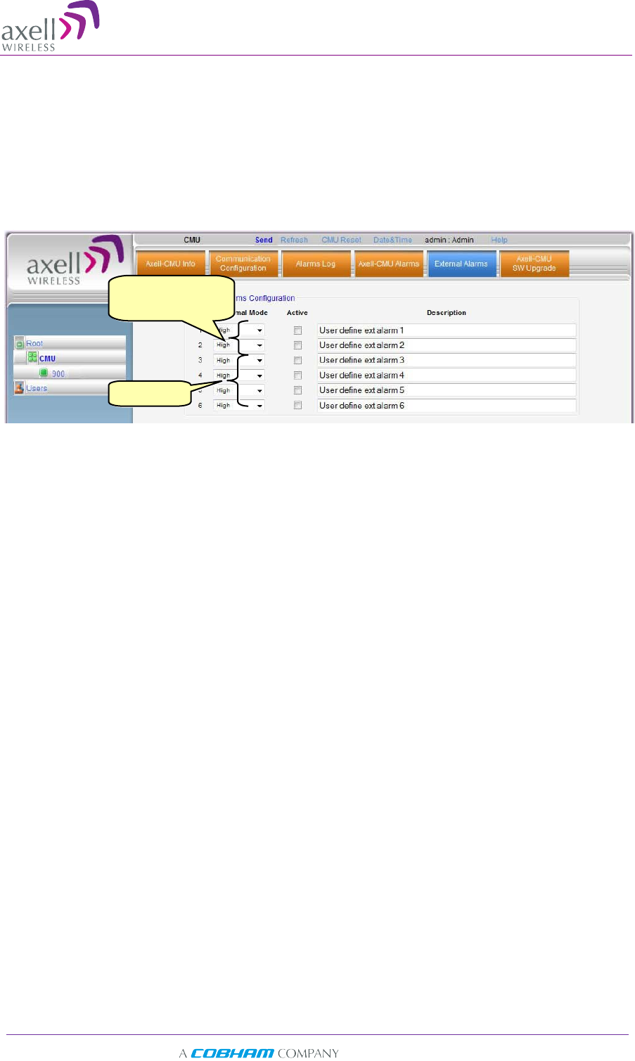
Any connected alarms (section 3.10) must be enabled and configured according to the
instructions provided in this section.
To configure external alarms
1. Click on CMU in the tree pane.
2. Click the External Alarms tab. The following dialog appears.
3. For each connected alarm:
• Checkmark the Active checkbox.
• Set the alarm Normal Mode as High or Low.
• In the Description field, assign the alarm an identifiable name.
Two Options for
External Alarms
Not in use
Axell D-SBR 3709S Repeater
PRODUCT DESCRIPTION AND USER’S MANUAL
28 Doc PN 00038UMCD Rev. 1.6 © Axell Wireless Ltd
4
4.
.5
5
C
Co
om
mm
mu
un
ni
ic
ca
at
ti
io
on
n
a
an
nd
d
S
Sy
ys
st
te
em
m
P
Pa
ar
ra
am
me
et
te
er
rs
s
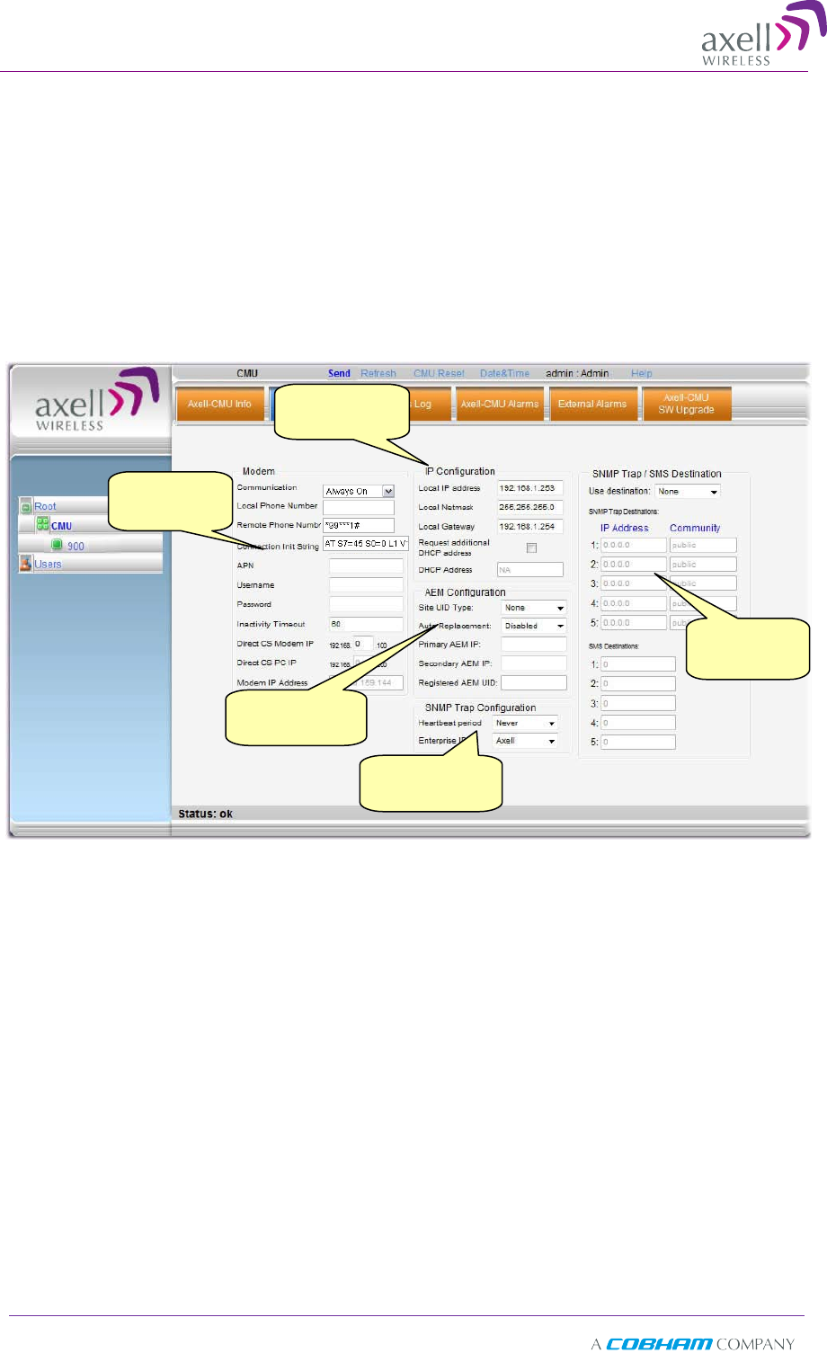
The Communication Configuration tab provides the IP, AEM and SNMP trap configuration
parameters. This section describes how to access the dialog. The following sub-sections
provide detailed information on each configuration option.
4.5.1 The Communication Configuration Tab
To access the Communication Configuration tab
In the left tree pane, click CMU. From the available tabs in the work area, choose the
Communication Configuration tab.
IP Address
settings
Modem
parameters
SNMP IP
destinations
Trap sending
frequency
AEM
configuration
Axell D-SBR 3709S Repeater
PRODUCT DESCRIPTION AND USER’S MANUAL
© Axell Wireless Ltd Doc PN 00038UMCD Rev. 1.6 29
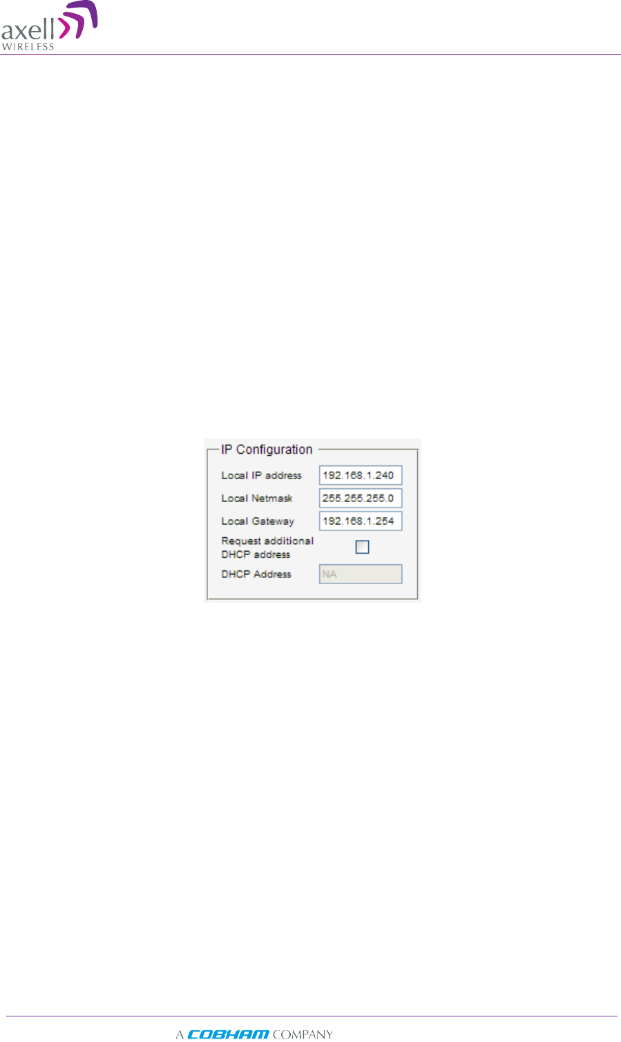
4.5.2 IP Address Setup and Repeater Name
The Repeater supports both Static and DHCP addresses. A unique technology enables
applying both types to the same Ethernet port. Both addresses may enable local and
remote management.
• Local IP Address – Static IP assigned by the user to the system. The default Static IP
address is 192.168.1.253. It is highly recommended to preserve this setup. In case
of a change, make sure you record the newly assign IP.
• DHCP Address – address assigned by DHCP server – used for remote management
via an Ethernet connection.
To assign the unit a name and IP address
1. Access the Communication tab according to section 4.5.1.
2. To assign the unit addresses:
• Local address - in the IP Configuration area, assign the unit the Local IP
address, Netmask and Gateway parameters provided by your system
administrator.
• DHCP server address – checkmark the option Request Additional DHCP
Address. The assigned address can be seen in the DHCP Address field.
Axell D-SBR 3709S Repeater
PRODUCT DESCRIPTION AND USER’S MANUAL
30 Doc PN 00038UMCD Rev. 1.6 © Axell Wireless Ltd
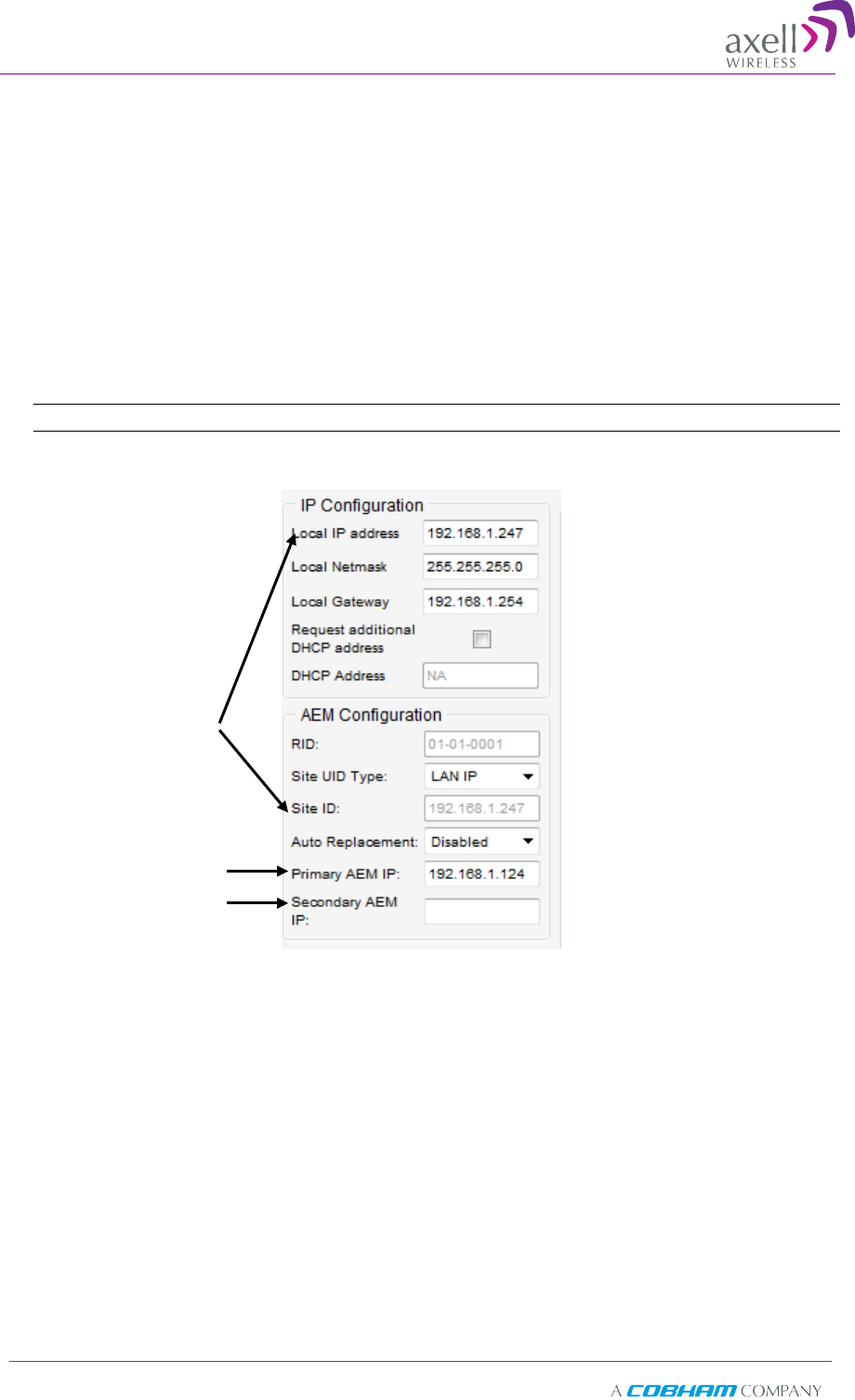
4.5.3 AEM (Axell Element Manager) Configuration
AEM repeater management configuration is performed only on the AEM side – it is only
required to add the new repeater (element) IP address to the AEM.
This section describes how to configure the repeater for Auto Replacement. Auto
Replacement is used when a repeater is replaced. The new repeater is assigned the
same IP address as the previous repeater and configured with Auto Replacement. This
enables the AEM to download the previous repeater configuration to the new repeater,
minimizing downtime.
To configure the repeater for AEM management
1. Access the Communication Configuration tab (see 4.5.1).
NOTE: The RID (Repeater ID) is automatically detected by the system.
2. To configure the replacement Repeater for Auto Replacement:
• Set Auto Replacement to Enable.
• Set Site UID Type to LAN IP – this identifies the site IP Address
• Verify that the repeater’s IP address is Fixed – section 4.5.2.
AEM server IP
address
Site ID set to
LAN IP
Axell D-SBR 3709S Repeater
PRODUCT DESCRIPTION AND USER’S MANUAL
© Axell Wireless Ltd Doc PN 00038UMCD Rev. 1.6 31
5
5
A
Ad
dm
mi
in
ni
is
st
tr
ra
at
ti
iv
ve
e
O
Op
pe
er
ra
at
ti
io
on
ns
s
The following administrative operations are described in this section:
• User Management – defining and changing users and passwords.
• Viewing the Repeater information such as software and hardware versions, serial
number, etc.
• Software upgrade
5
5.
.1
1
U
Us
se
er
r
M
Ma
an
na
ag
ge
em
me
en
nt
t
This section describes how to perform the user management operations. By default, two
users belonging to one of three authentication levels are defined on the Repeater.. You
may add new users, modify or delete existing users.
5.1.1 User Levels
Three user levels are available:
• Admin – has access to all administration and configuration options, including user
management. (Default Password admin and default User Name admin.)
• Operator – has access to all configuration options except for the Users list or the
Loaders screen.
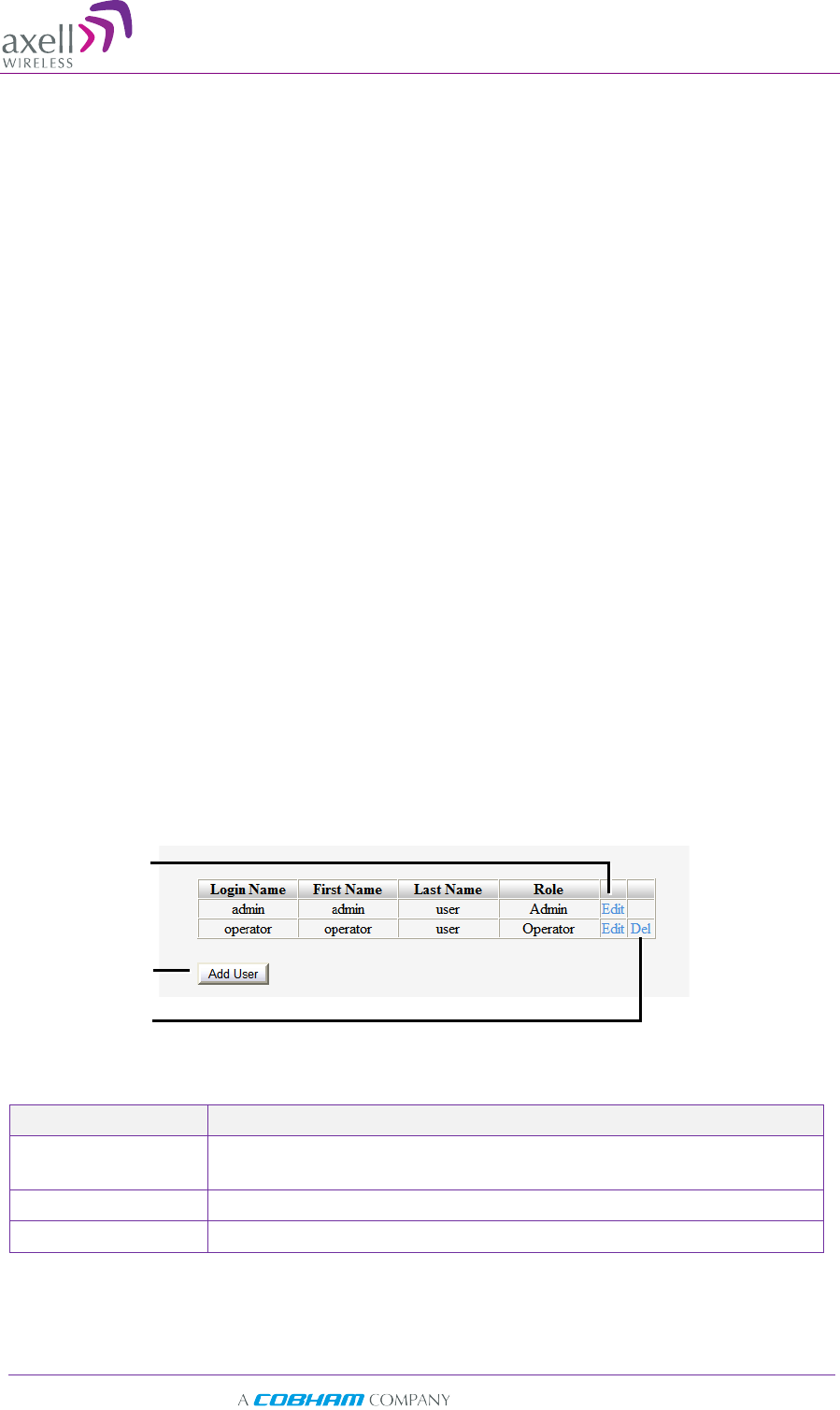
5.1.2 Viewing the List of Defined Users
To display the User Administration pane
From the Tree Pane, select Users. The list of users is displayed in the Configuration
Pane according to the identifying information and authentication level (Role).
The following table provides a description of the Users dialog options.
Option Description
Add User (button) Adds a new user with to user defined access level and
password.
Del(ete) Deletes a selected user from the list.
Edit Enables changing the definitions of an existing user.
Edit user
Delete user
Add user
Axell D-SBR 3709S Repeater
PRODUCT DESCRIPTION AND USER’S MANUAL
32 Doc PN 00038UMCD Rev. 1.6 © Axell Wireless Ltd
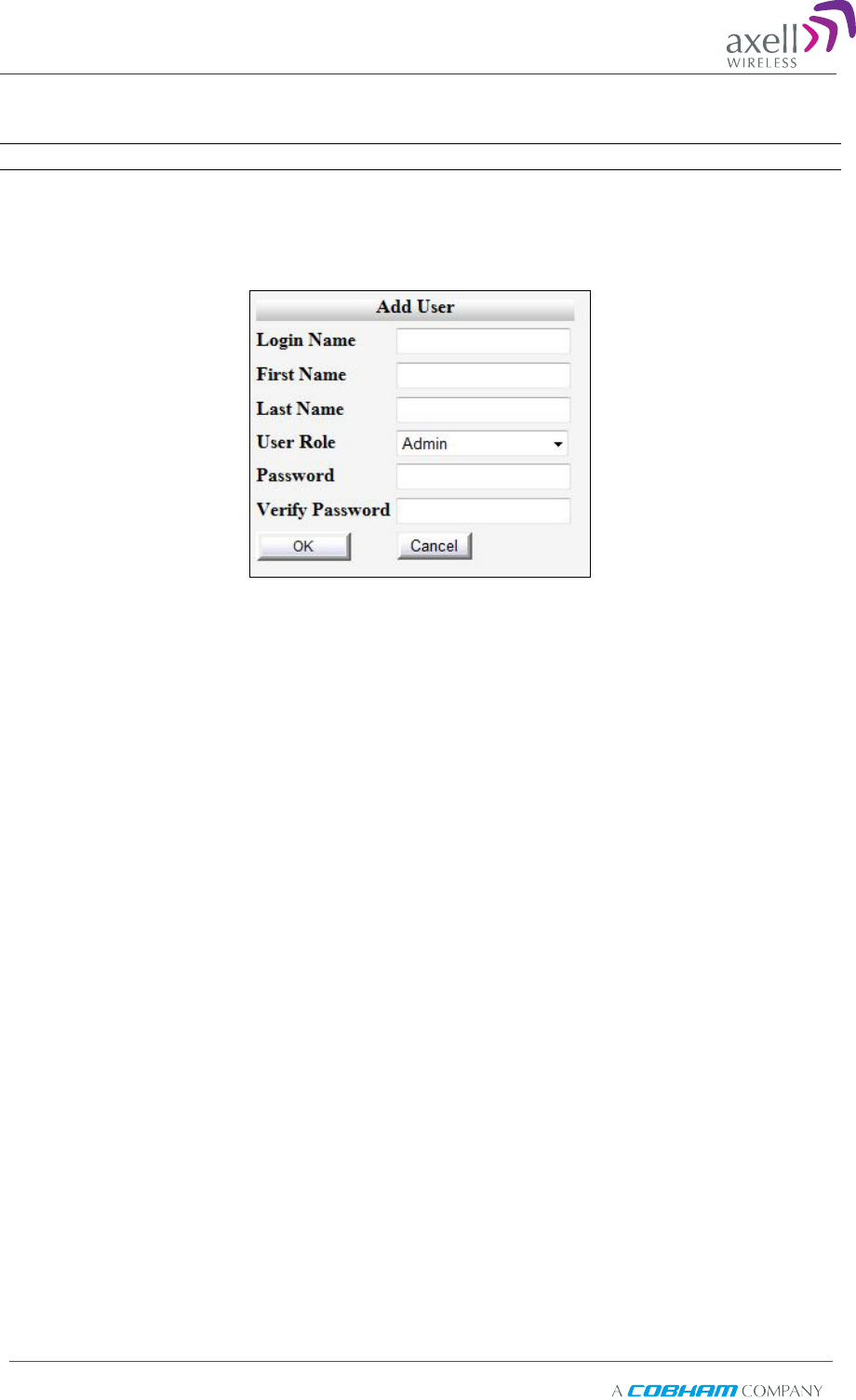
5.1.3 Adding Users
NOTE: User name and password entries are case sensitive.
To add a user
1. From the Tree Pane, select Users. The list of users is displayed in the User's Pane.
2. From the User's Pane, click Add User. The Add User dialog box is displayed.
3. Enter the Login Name – name used by user to login.
4. Type the user's First Name and Last Name – used to identify the user.
5. Select the User Role – access level. This defines the operations that the user will be
able to perform.
6. Enter the Password and in Verify Password enter the password again for
verification.
7. Click OK.
5.1.4 Editing a User
To modify user definitions
1. From the Tree Pane, select Users. The list of users is displayed in the User's
Pane.
2. Select the User to be edited in the list.
3. Click Edit. The user definitions dialog appears.
4. Make the required changes and click OK.
Axell D-SBR 3709S Repeater
PRODUCT DESCRIPTION AND USER’S MANUAL
© Axell Wireless Ltd Doc PN 00038UMCD Rev. 1.6 33
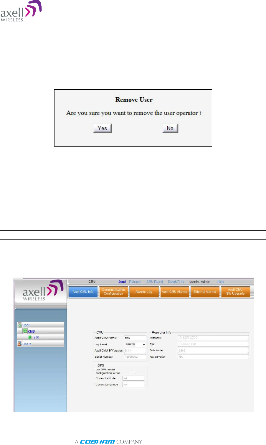
5.1.5 Deleting a User
To delete a user
1. From the Tree Pane Select Users. The list of users is displayed in the User's Pane.
2. Select the User to be deleted in the list.
3. From the User's Pane, click Del. An authorization message dialog box is displayed.
4. Click Yes. The User’s name is removed from the list.
5
5.
.2
2
V
Vi
ie
ew
wi
in
ng
g
R
Re
ep
pe
ea
at
te
er
r
a
an
nd
d
B
Ba
an
nd
d
I
In
nf
fo
or
rm
ma
at
ti
io
on
n
5.2.1 Viewing Repeater Level Information
Use the CMU-Info screen to view the hardware and software versions of the Axell
D-SBR Repeater. In addition, the screen provides configuration options for setting the
minimum Log Level and assigning the Repeater a recognizable name.
NOTE: Read-only or irrelevant parameters are grayed out.
To access the Repeater Information window
1. From the Tree Pane, select the CMU item.
2. Select the Axell CMU Info tab.
Axell D-SBR 3709S Repeater
PRODUCT DESCRIPTION AND USER’S MANUAL
34 Doc PN 00038UMCD Rev. 1.6 © Axell Wireless Ltd
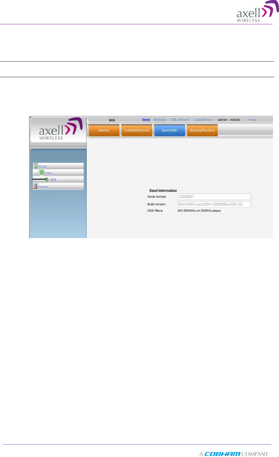
5.2.2 Viewing Band Information
Use the Repeater Information screen to view the hardware and software versions of
the Axell D-SBR Repeater and to assign the Repeater a recognizable name.
Note: Usually, these fields are grayed-out. Grayed-out fields indicate that the display is Read-only.
Active fields indicate that the parameter values can be defined.
To access the Repeater Information window
1. From the Tree Pane, select the repeater Band (i.e. 900).
2. Select the Repeater Info tab. The relevant parameters are displayed.
Select the
Band
Axell D-SBR 3709S Repeater
PRODUCT DESCRIPTION AND USER’S MANUAL
© Axell Wireless Ltd Doc PN 00038UMCD Rev. 1.6 35
5
5.
.3
3
C
CM
MU
U
S
So
of
ft
tw
wa
ar
re
e
U
Up
pg
gr
ra
ad
de
e
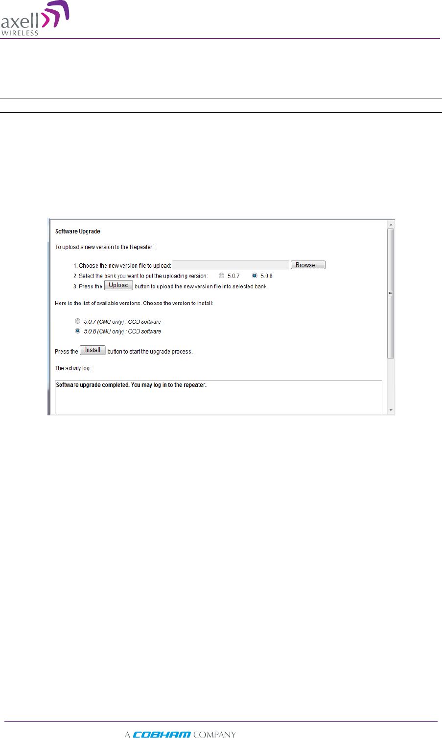
The procedure described in this section is used to upgrade the repeater CMU.
Note: This procedure is performed for every new management version.
To Upgrade the Repeater SW
1. From the Tree Pane, select CMU.
2. Select the Axell CMU SW Upgrade tab. The CMU SW Upgrade screen shown below
appears.
3. Choose the version to upload and perform the procedure according to the
instructions in the screen.
5
5.
.4
4
B
Ba
ac
ck
ku
up
p/
/R
Re
es
st
to
or
re
e
o
of
f
R
Re
ep
pe
ea
at
te
er
r
C
Co
on
nf
fi
ig
gu
ur
ra
at
ti
io
on
n
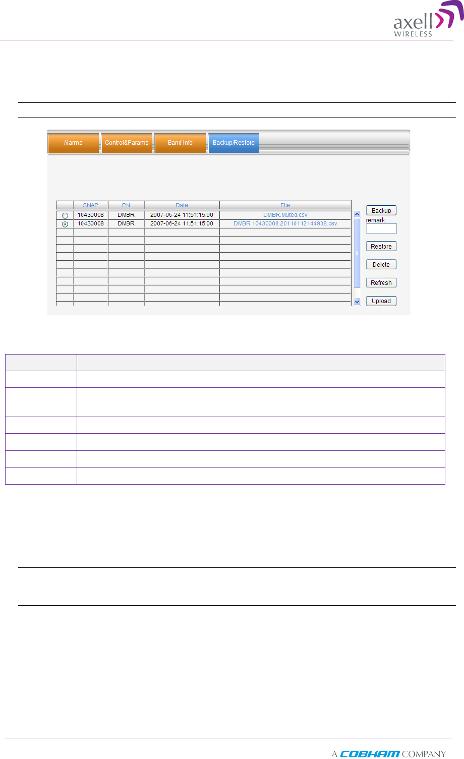
The D-SBR Web GUI management application enables the backup and restore of the
repeater configuration files. This section provides a description of the following
procedures:
• Backup of current Repeater configuration
• Restoring previous Repeater configuration from available files
• Uploading new configuration file from computer
• Saving configuration settings to other location (i.e. computer)
Axell D-SBR 3709S Repeater
PRODUCT DESCRIPTION AND USER’S MANUAL
36 Doc PN 00038UMCD Rev. 1.6 © Axell Wireless Ltd
To access Backup/Restore tab
1. From the Tree Pane, select the Band item (i.e. 900).
2. Select the Backup/Restore tab. The following tab appears.
Note: The following figure is only an example of the Backup/Restore tab.
The following table provides a description of the available options (buttons) in the
Backup /Restore tab shown above.
Button Description
Backup Used to backup the current repeater configuration. See section 5.4.1.
Remark
Used to assign the repeater configuration file (to be backed up) a
recognizable name. See section 5.4.1.
Restore Used to restore previous repeater configuration. See section 5.4.2.
Delete Select file from list and click Delete to remove.
Refresh
Click Refresh to list of available configuration files
Upload Used to upload new configuration file to repeater. See section 5.4.3.
5.4.1 Backup of Repeater Configuration
To perform backup procedure
1. To assign the configuration file a recognizable name, enter a name in the remark
field.
Note: This must be performed before performing the backup operation; otherwise the file will
automatically be assigned a name according to the backup date and unit ID. The name cannot
be modified once the backup has been performed.
2. Click the Backup button located on the right-hand side of the tab.
3. The file will be added to the table displayed in the Backup/Restore tab.

Axell D-SBR 3709S Repeater
PRODUCT DESCRIPTION AND USER’S MANUAL
© Axell Wireless Ltd Doc PN 00038UMCD Rev. 1.6 37
5.4.2 Restoring Previous Repeater Configuration
To restore previous configuration
1. Select the required configuration file (enable corresponding radio button) from the
available list in the Backup/Restore tab.
2. Click the Restore button.
Note: The following figure is only an example of the Backup/Restore tab.
3. Click on the Control and Params tab and verify that the required configuration
settings have been restored.
5.4.3 Uploading New Configuration File to Repeater
To upload configuration file to Repeater
1. Click the Upload button.
Note: The following figures are oly an example of the Backup/Restore tab.
2. Select the file from the Browse dialog and click Open.
3. The file appears in the list displayed in the Backup/Restore table.
5.4.4 Saving Configuration File to Computer
To save a configuration file from the available list in the Backup/Restore table to a
location in a connected computer:
• Select file from list.
• Click the link in the File column.
• Select the location in the Browse dialog.
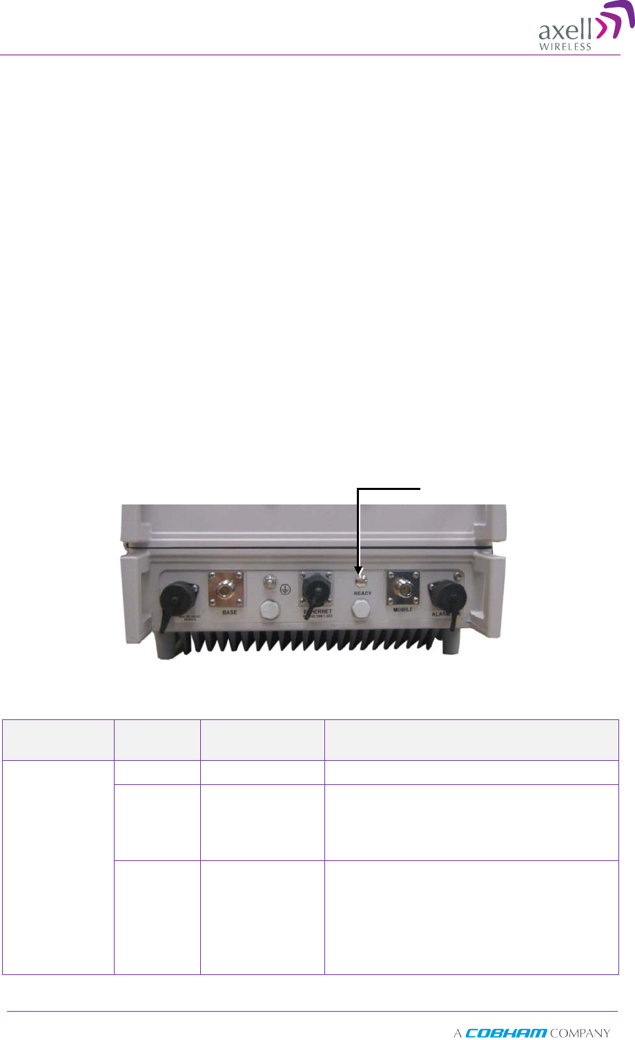
Axell D-SBR 3709S Repeater
PRODUCT DESCRIPTION AND USER’S MANUAL
38 Doc PN 00038UMCD Rev. 1.6 © Axell Wireless Ltd
6
6
M
Mo
on
ni
it
to
or
ri
in
ng
g
a
an
nd
d
T
Tr
ro
ou
ub
bl
le
es
sh
ho
oo
ot
ti
in
ng
g
The D-SBR repeater provides the following indications of Repeater failure:
• LEDs: on Repeater front panel and inside the repeater
• Alarms screen in Web access application
• Alarms Log – used to view a record of past generated alarms
The following sections provide a description of the troubleshooting procedures according
to the Repeater LED indicators and the Web access Alarms.
6
6.
.1
1
L
LE
ED
D
T
Tr
ro
ou
ub
bl
le
es
sh
ho
oo
ot
ti
in
ng
g
The D-SBR High Power Repeater provides an external LED and two internal LEDs,
indicating the repeater operation status.
6.1.1 External LED
A READY LED is located on the underside panel of the repeater.
Figure 6-1. READY LED located on Underside Panel
The following table provides a description of the READY LED troubleshooting procedures.
LED Color Status and
Probable Cause
Recommendation
READY/
POWER
(External LED)
Green Normal operation -
Red Power failure Corrective action: Turn off the Repeater (this
action causes a reset of the function), and
turn it on anew. If the fault resumes, replace
the unit.
Blinking
Orange/red
User mute
System mute
- Due to isolation
problem or
temperature
Check gain of the repeater, if gain is
minimum, then it is an isolation problem ->
improve isolation.
Turn OFF the Repeater (resets the function),
and turn it ON again. If the fault resumes,
replace the unit.
READY
LED
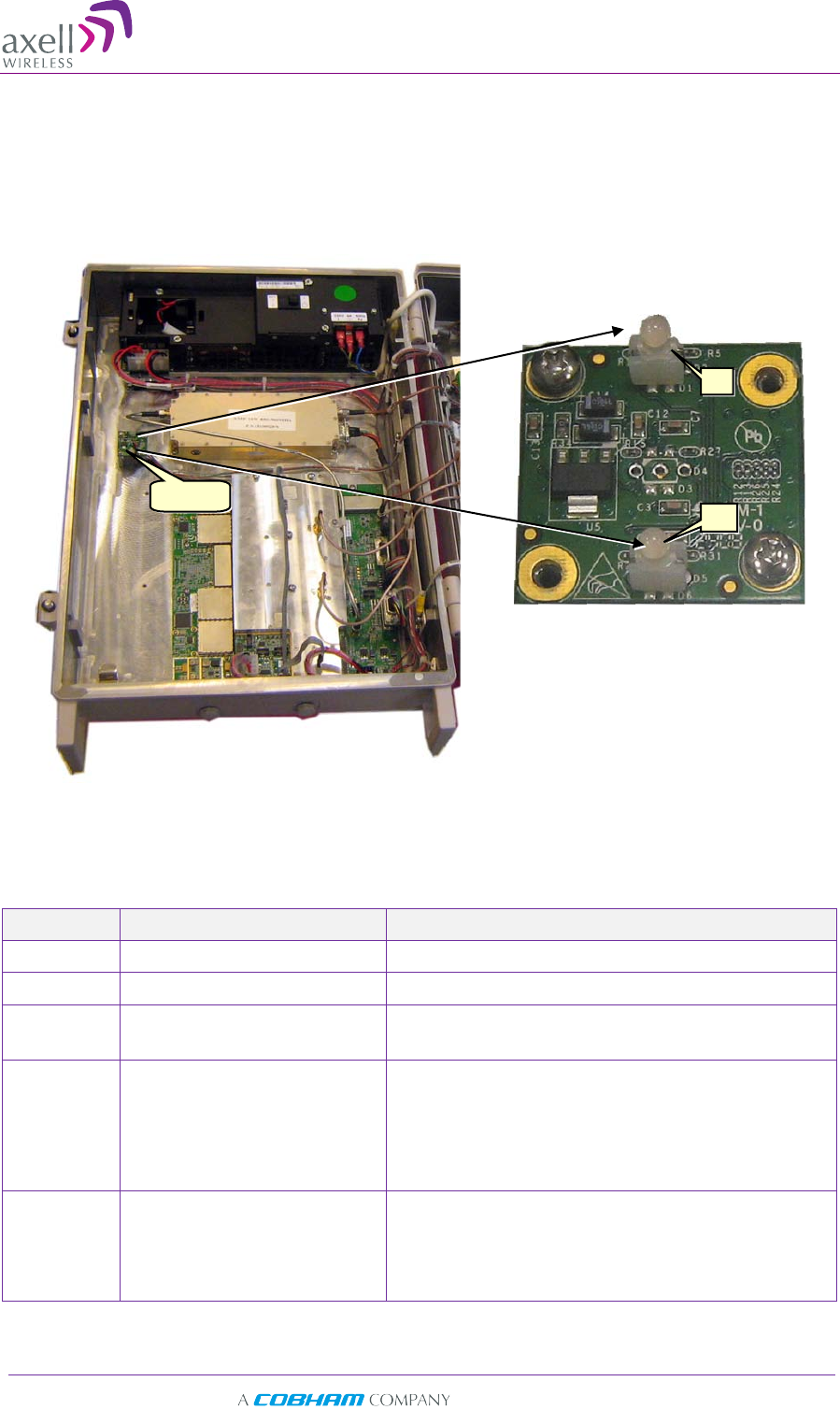
Axell D-SBR 3709S Repeater
PRODUCT DESCRIPTION AND USER’S MANUAL
© Axell Wireless Ltd Doc PN 00038UMCD Rev. 1.6 39
6.1.2 Internal LEDs
Two LEDs (UL and DL) located inside the repeater provide an indication on the UL and
DL signals.
The following figures show an example of the LED locations (the location may differ on
your unit).
Figure 6-2. Axell D-SBR 3709S Internal View
The following table provides a description of the UL and DL LED troubleshooting
procedures.
Color Status and Probable Cause Recommendation
Green Normal operation -
Red Major error The Repeater must be replaced
Blinking
Green
Low input signal from
Donor/Mobile antenna
Check the Donor antenna input power
Orange High out of band signal input
power from Donor/Mobile
antenna
Redirect donor azimuth or add attenuator before
base port.
Caution! Disconnect power to the repeater before
connecting the attenuator. Once installed,
reconnect power.
Blinking
Orange/red
User mute
System mute
- Due to isolation problem or
temperature
Check gain of repeater. If gain is minimum, then it is
likely an isolation problem -> improve the isolation.
Reset the Repeater by turning if off and on again. If
the fault continues, replace the unit.
DL
UL
LEDs
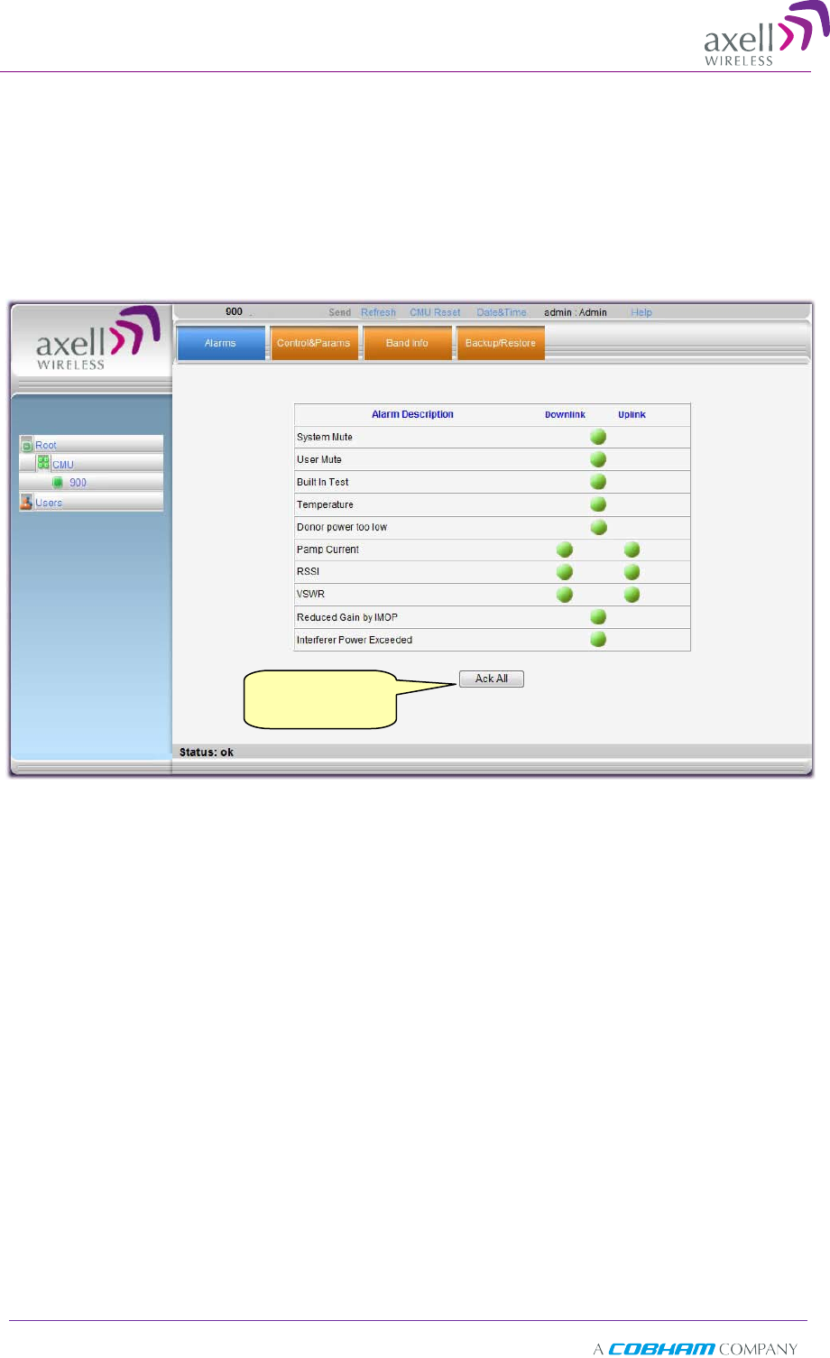
Axell D-SBR 3709S Repeater
PRODUCT DESCRIPTION AND USER’S MANUAL
40 Doc PN 00038UMCD Rev. 1.6 © Axell Wireless Ltd
6
6.
.2
2
R
Re
ep
pe
ea
at
te
er
r
A
Al
la
ar
rm
ms
s
a
an
nd
d
T
Tr
ro
ou
ub
bl
le
es
sh
ho
oo
ot
ti
in
ng
g
The Alarms tab provides the alarms generated by the Repeater, enabling the user to
monitor the system operation.
To access the Alarms window
From the Tree Pane, select the Band item (e.g. 900) and choose the Alarms tab. The
relevant parameters are displayed. See the following page for alarm descriptions.
Click
Ack All to
reset the alarms

Axell D-SBR 3709S Repeater
PRODUCT DESCRIPTION AND USER’S MANUAL
© Axell Wireless Ltd Doc PN 00038UMCD Rev. 1.6 41
Alarm
Fault and most probable
cause Recommendation
System Mute
Cause: Repeater amplification is
muted (automatically). -----
User Mute
Cause: Repeater amplification is
muted (manually) as a result of
an operator action.
-----
Built In Test Cause: Self test. -----
Temperature Fault: High temperature.
Most probable cause: Unit
temperature becomes high.
Excessive heat.
Corrective action: Check the Repeater
case for external causes (sun, hot
environment, air flow is blocked).
Eliminate the reason for excessive
heat.
Donor Power too
Low
The signal from the Donor
antenna is too low. Check connections and antenna
position.
PAmp Current Fault:
the Pre Amplifier current
exceeds the allowed limits.
Fault in the DL or UL path.
Most probable cause:
Downlink (Uplink) power
amplifier module outputs a low
current.
Corrective action: Check the LEDs in
the Repeater (see 6.1).
RSSI Fault: Fault in the DL or UL path
Most probable cause: Excessively
high input signal
Corrective action: Check the LEDs in
the Repeater (see 6.1).
VSWR
Fault: The return loss of the
Downlink antenna or cable
connection exceeds 6 dB (VSWR
3:1).
Most probable cause: This alarm
provides an indication of the
status of the cable connected to
the antenna. If a cable is
defective, the VSWR is decreased
and the alarm is triggered again.
Corrective action:
Check cable
connected to the antenna.
Reduced Gain by
IMOP Description:
Shows when the
iMOP mechanism was activated
in order to re
spond to detected
oscillations.
GREEN – normal operation – no
oscillations were detected.
RED – oscillations were detected
and the system reduced gain in
order to eliminate the
oscillations.
Corrective action: Check the Donor and
Mobile antenna installations for
isolation. After isolation is within the
required levels, the system will
automatically increase gain (since it
will no longer affect oscillations) and
the LED will turn GREEN.
Interferer Power
Exceeded
Indicates if there is any external
interference at a level that may
affect the operation of the unit.
Green –
low or no interference.
Unit operation is not affected.
Red –
high external interference
that may affect the operation of
the unit.
It is recommended to identify the
source of the interference and distance
the source or the unit from each other.
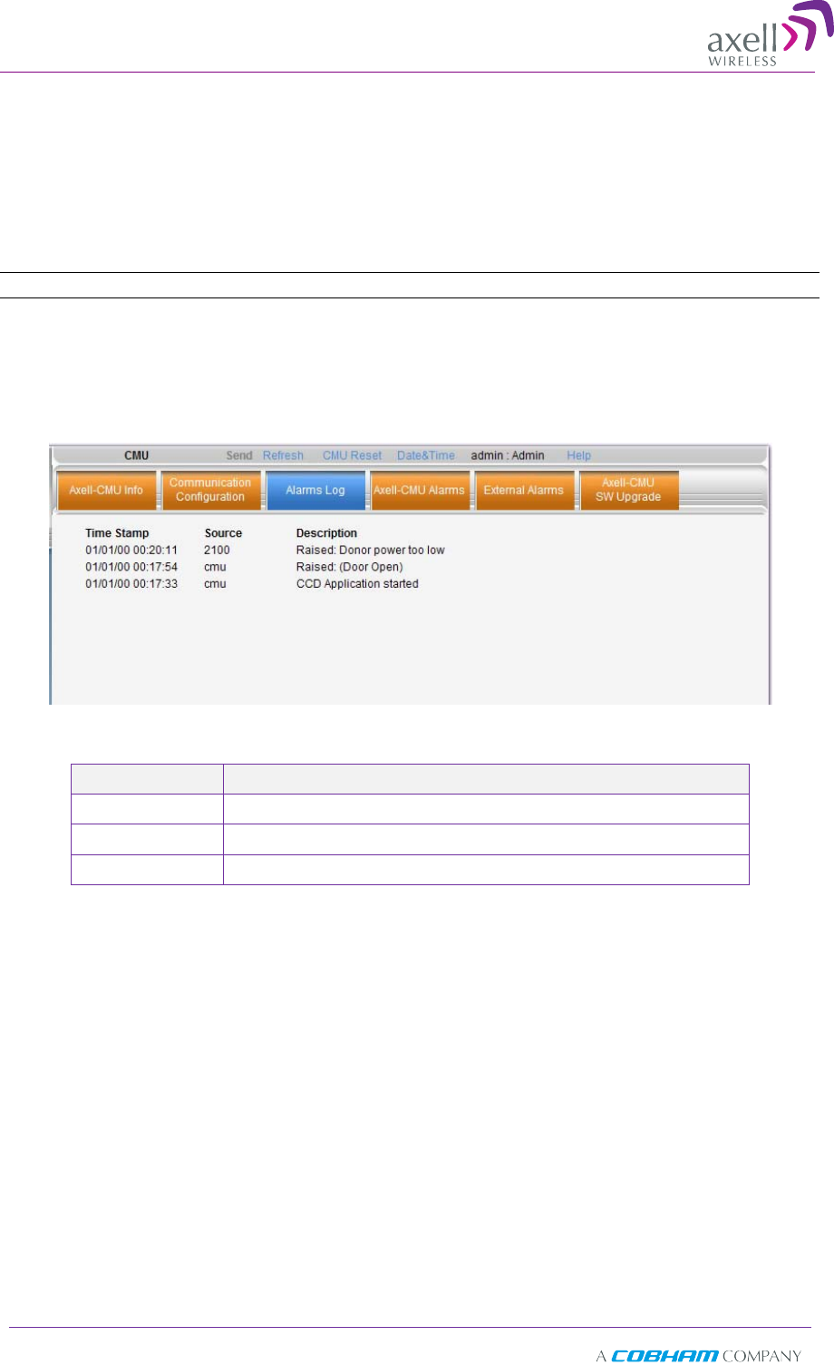
Axell D-SBR 3709S Repeater
PRODUCT DESCRIPTION AND USER’S MANUAL
42 Doc PN 00038UMCD Rev. 1.6 © Axell Wireless Ltd
6
6.
.3
3
V
Vi
ie
ew
wi
in
ng
g
t
th
he
e
A
Al
la
ar
rm
ms
s
L
Lo
og
g
The Alarms Logs screen lists the alarms (events) that have occurred. The CMU
maintains log files listing every alarm triggered and in the Repeater. This screen
provides an analysis tool to get information of any event that has occurred, its
originator, when, if they return, and their type.
Note: Set the clock in order to synchronize the events time of occurrence (see 4.3.3).
To view the CMU log screen:
1. Open and login to the Web application.
2. From the Tree Pane, select CMU.
3. Click Alarms Logs. CMU displays the Alarms Log Table.
Item Description
Time Stamp The date and time the alarm was created
Source ID of Network Element
Description Description of event that caused the alarm
Axell D-SBR 3709S Repeater
PRODUCT DESCRIPTION AND USER’S MANUAL
© Axell Wireless Ltd Doc PN 00038UMCD Rev. 1.6 43
Appendix A: Specifications (@+25°C)
Electrical
Parameter Downlink Uplink
Frequency Range (GSM) 935-940MHz 896-901MHz
Passband Gain 90 dB
Passband Ripple ± 2 dB ± 2 dB
Gain Attenuation Range 0-25 dB (in 1 dB steps)
Composite Output Power +37dBm +23dBm
Number of Filters (*) 1 to 8
Noise Figure @ Maximum Gain
(typical) 5 dB
Propagation Delay 6 µsec
General
Power Supply 110VAC, 350W
Total RF Input Power (No Damage) + 10 dBm
Impedance Level 50 Ohm
RF Connector N-Type, Female
V.S.W.R 1.5:1
Environmental
Operating temperature -4 to +122°F (-20 to +50°C)
Storage temperature -22 to +158°F (-30 to +70°C)
Dimensions W x H x D 540 x 382 x 313 mm
Weight 33kg
Enclosure IP-65, NEMA 4
Conformance Standard FCC
(*) Supports any BW option 200 KHz - 5MHz by setting the start-stop frequency