PBE Europe as Axell Wireless MBF3709S 900MHz Fibre fed Band Selective Booster User Manual
Axell Wireless 900MHz Fibre fed Band Selective Booster
UserManual.wiki
>
PBE Europe as Axell Wireless
>
MBF3709S User Manual
User Manual
Navigation menu
Upload a User Manual
Namespaces
Wiki Guide
HTML
PDF
Info
Views
User Manual
Discussion / Help
Navigation
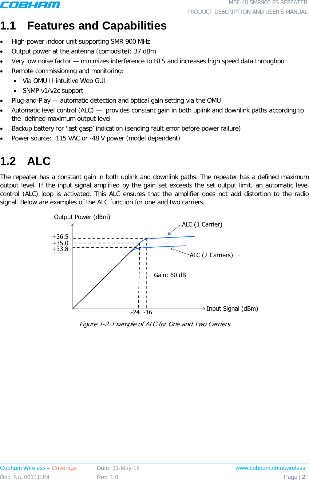
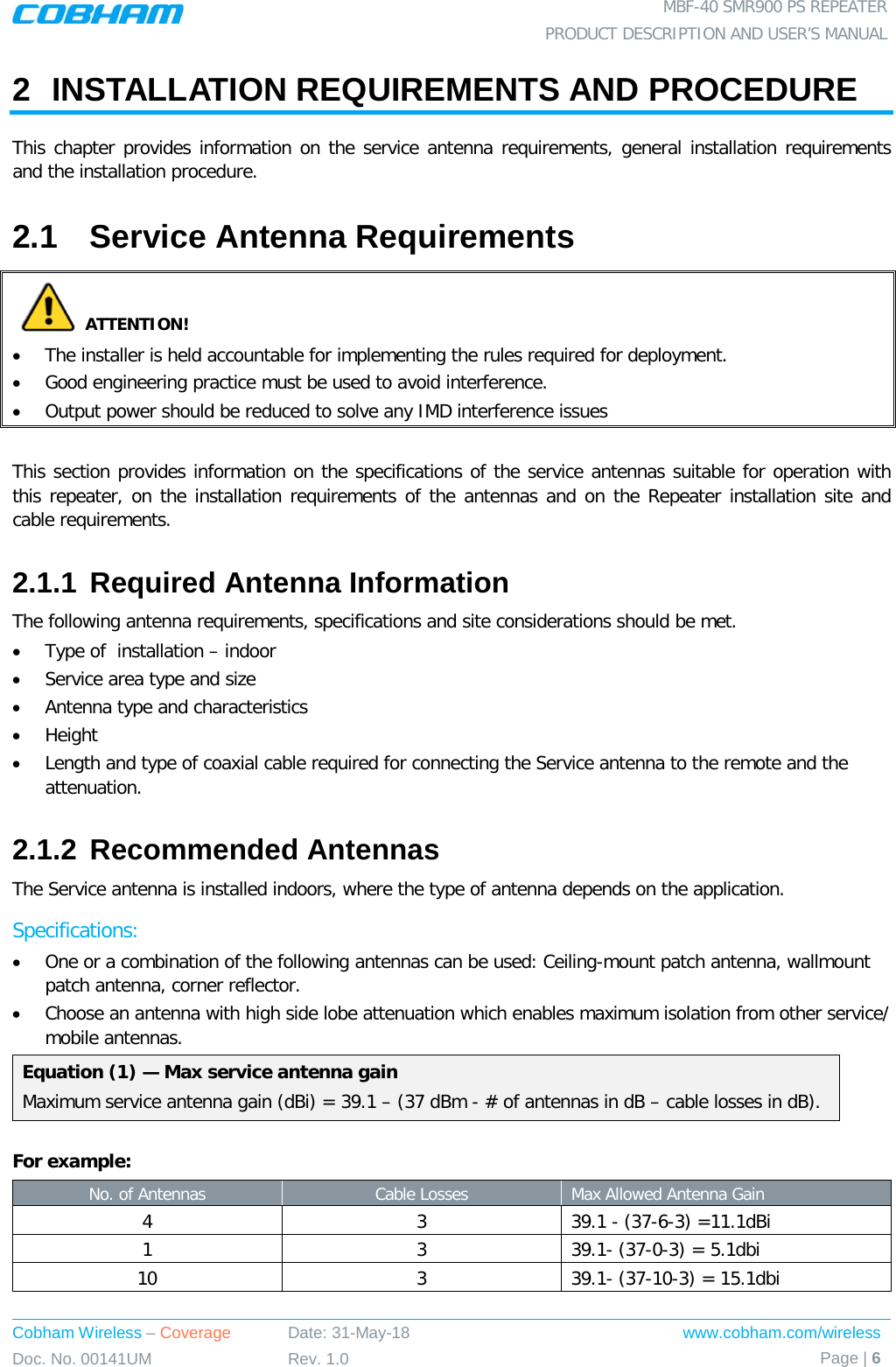
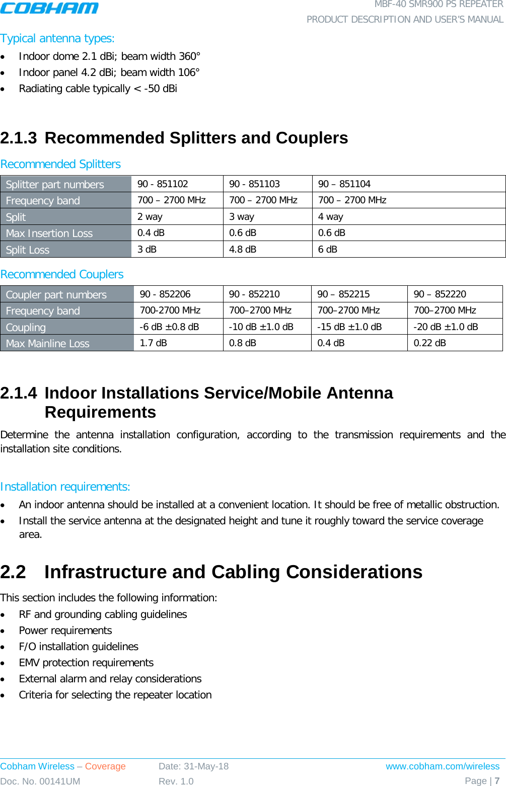
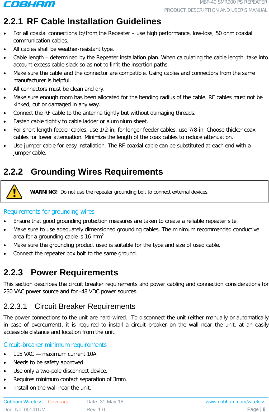
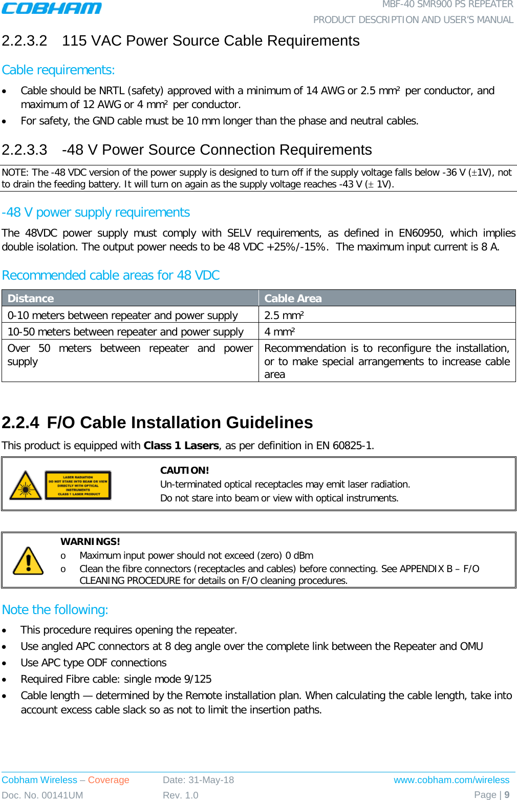
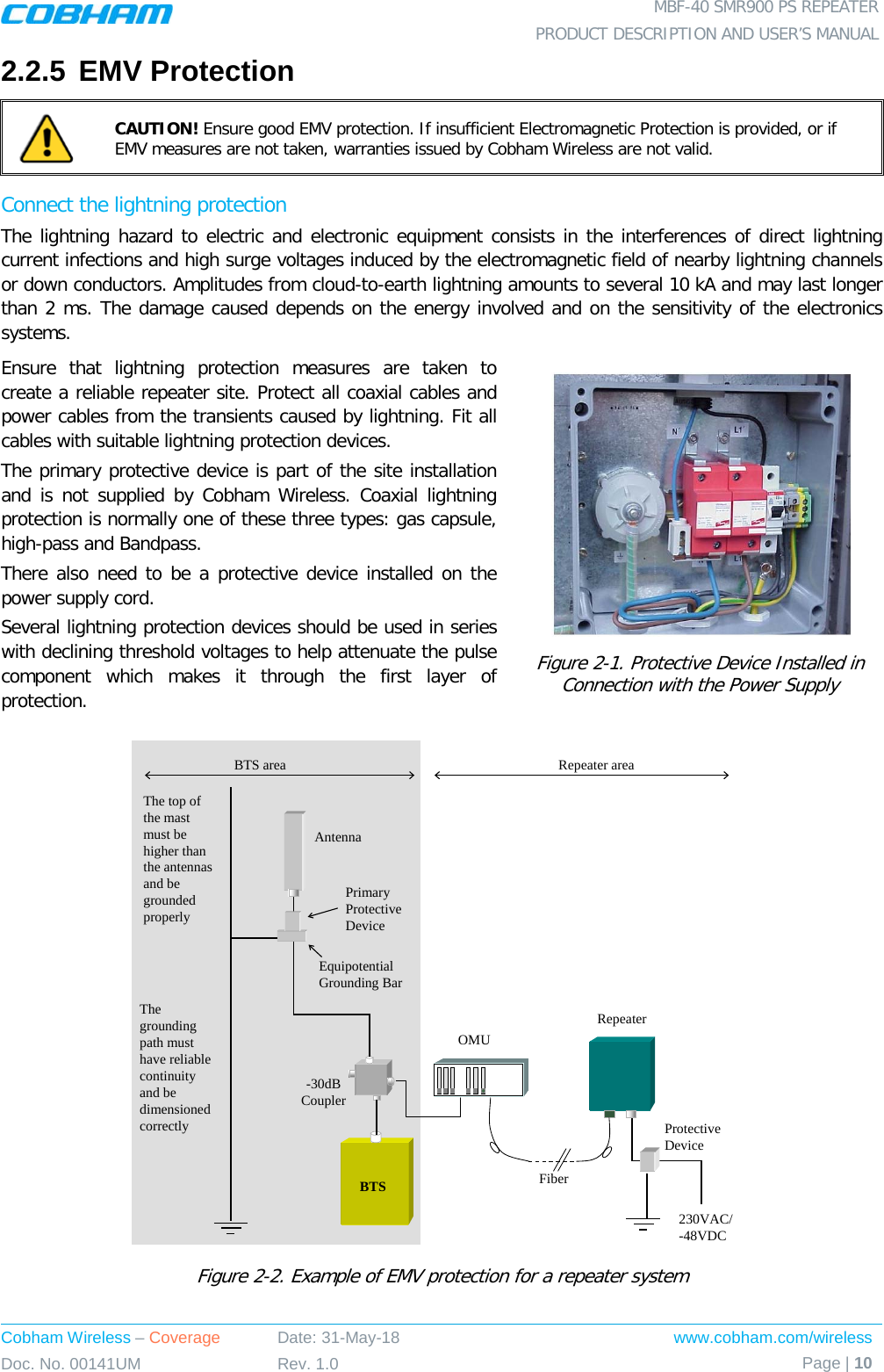
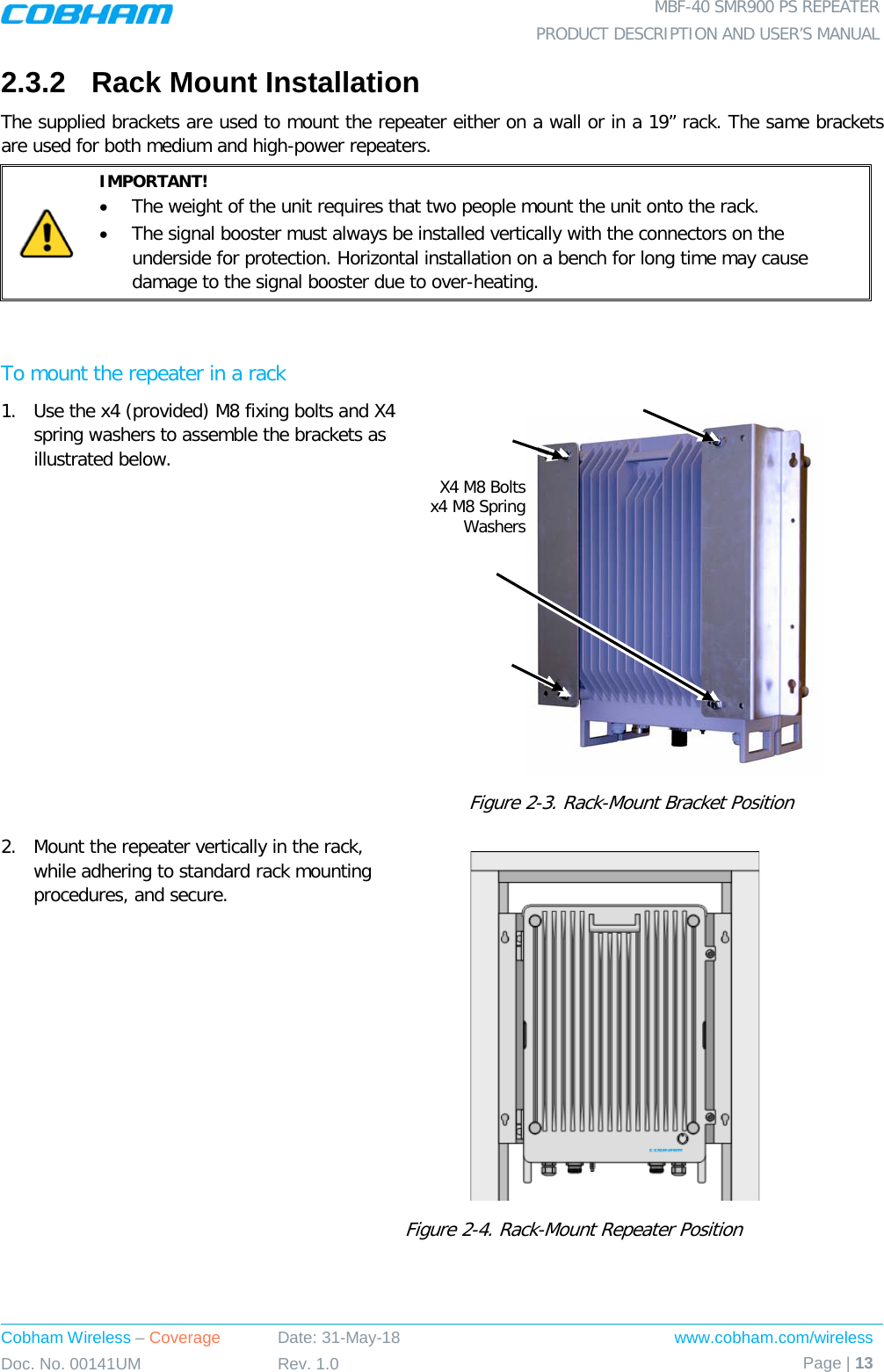
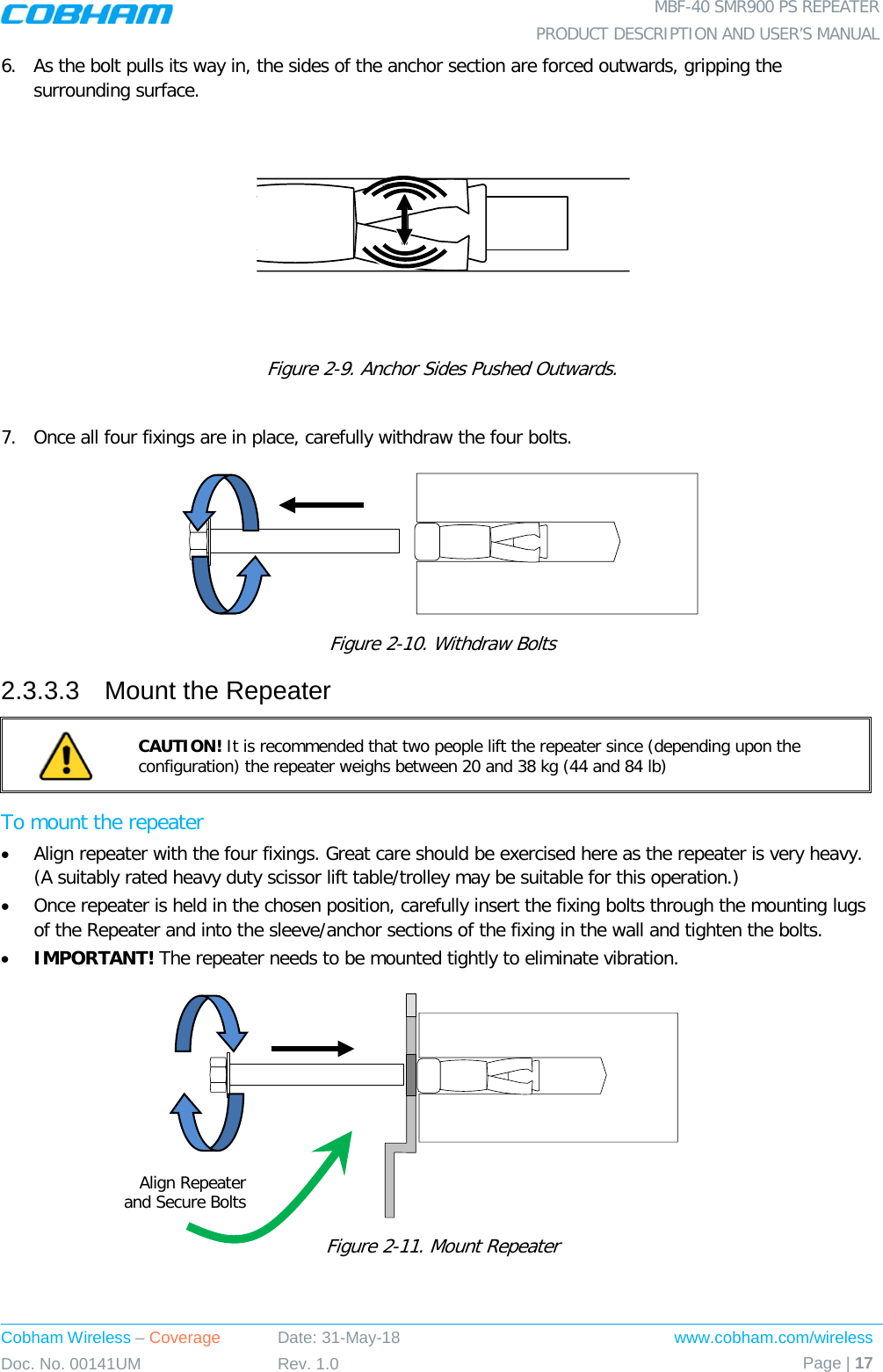
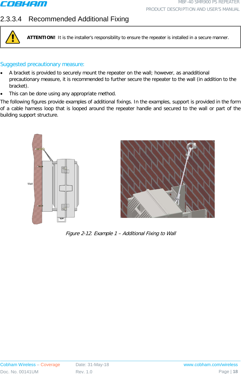
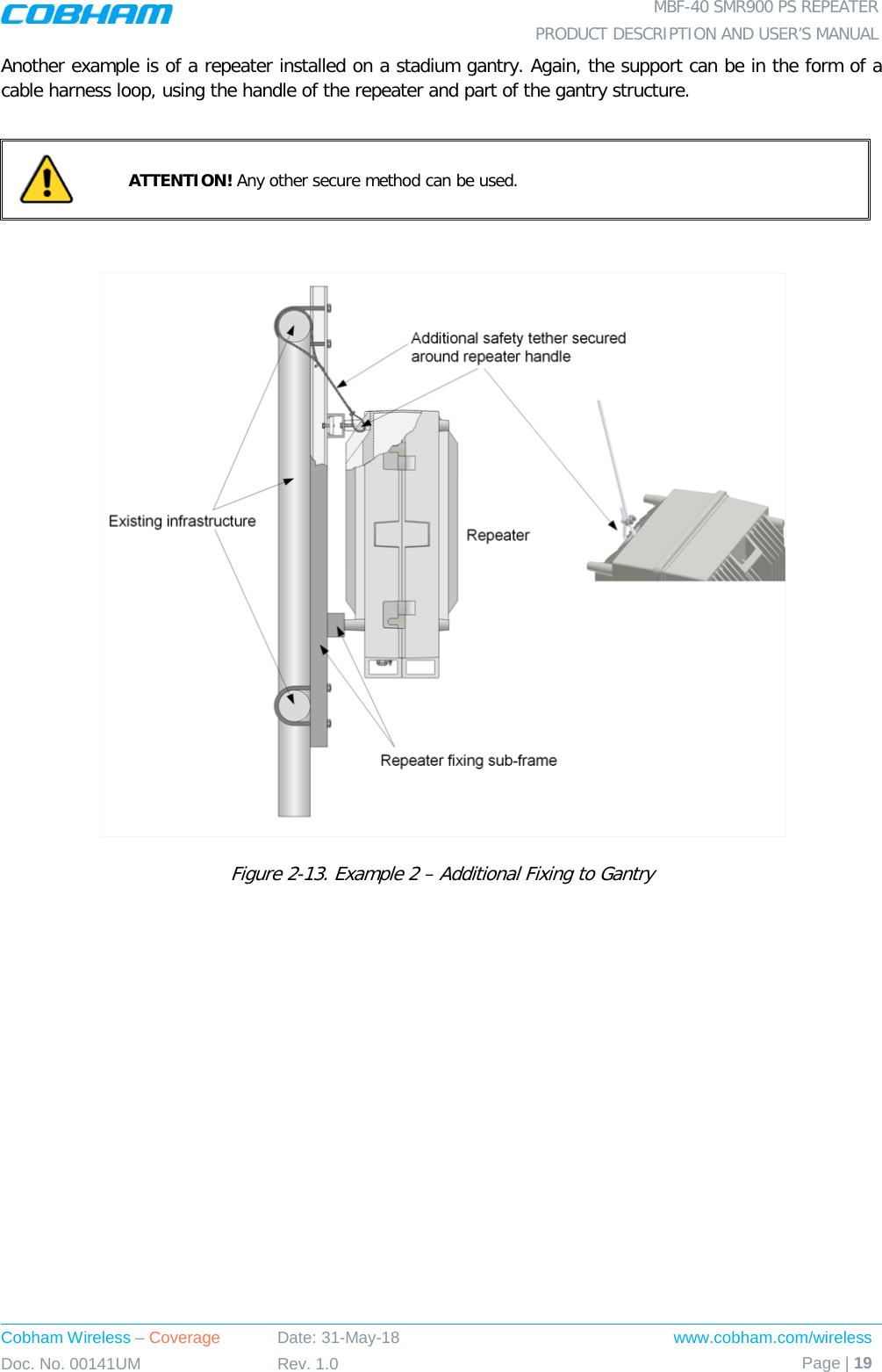
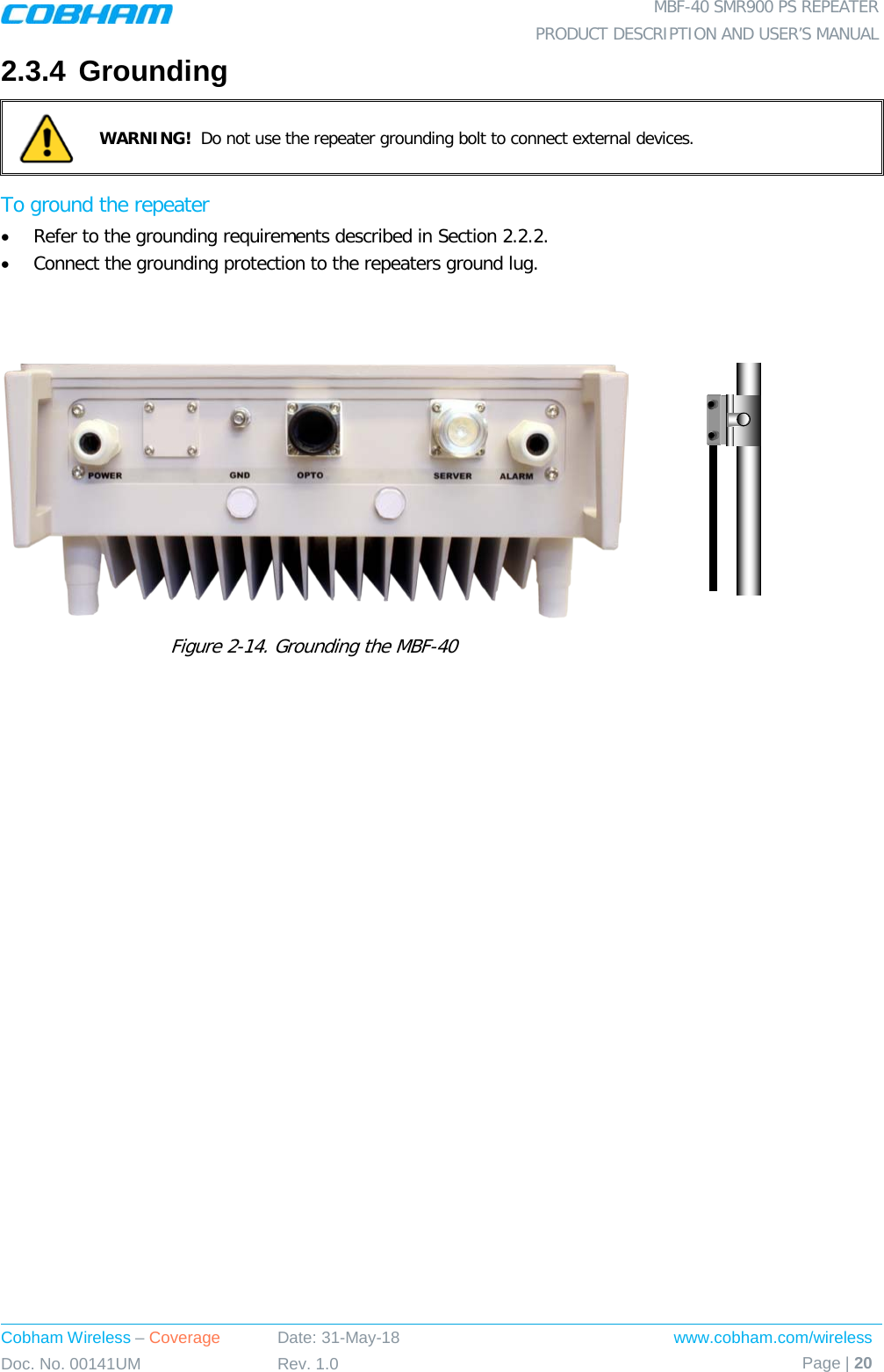
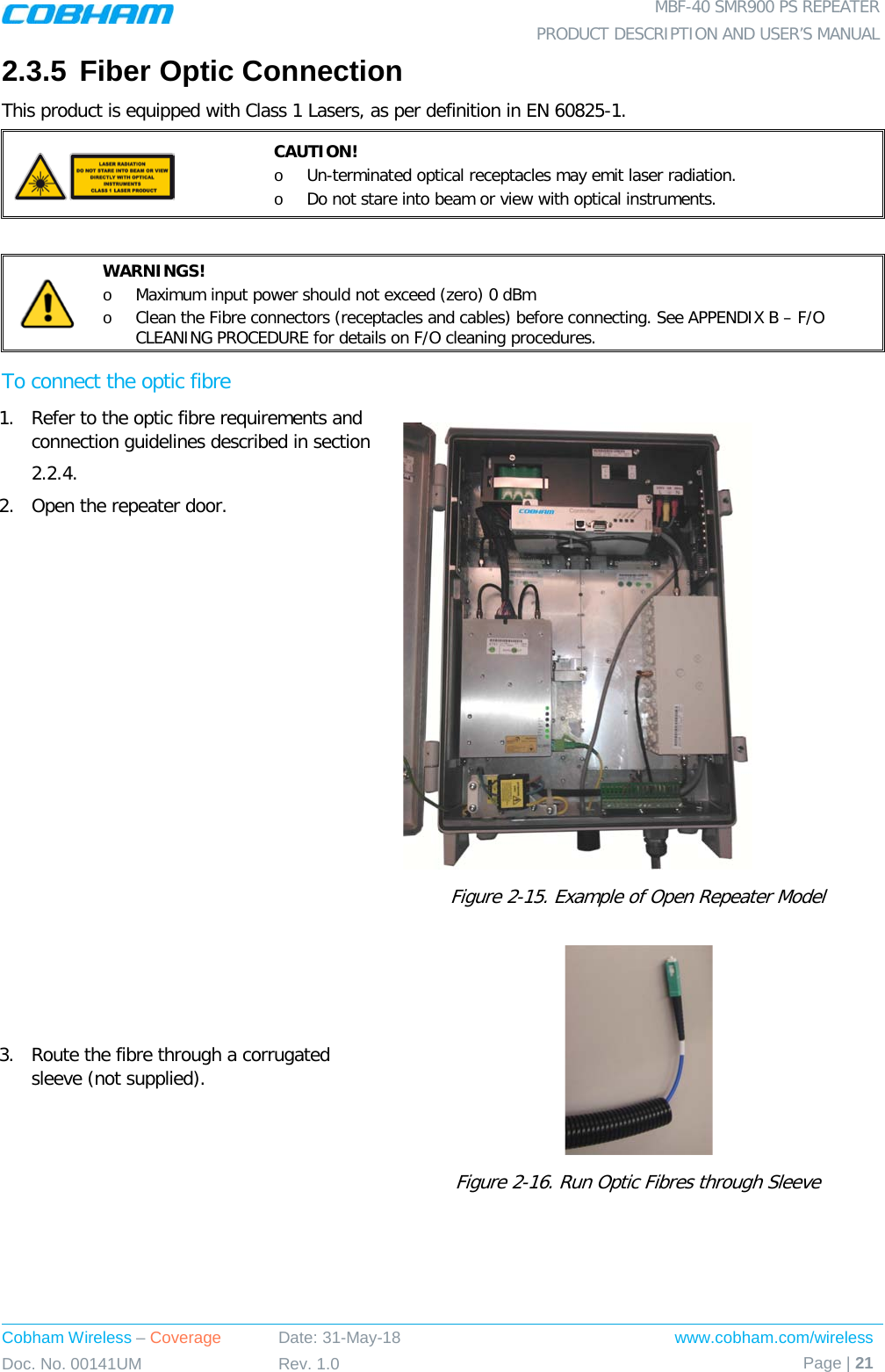
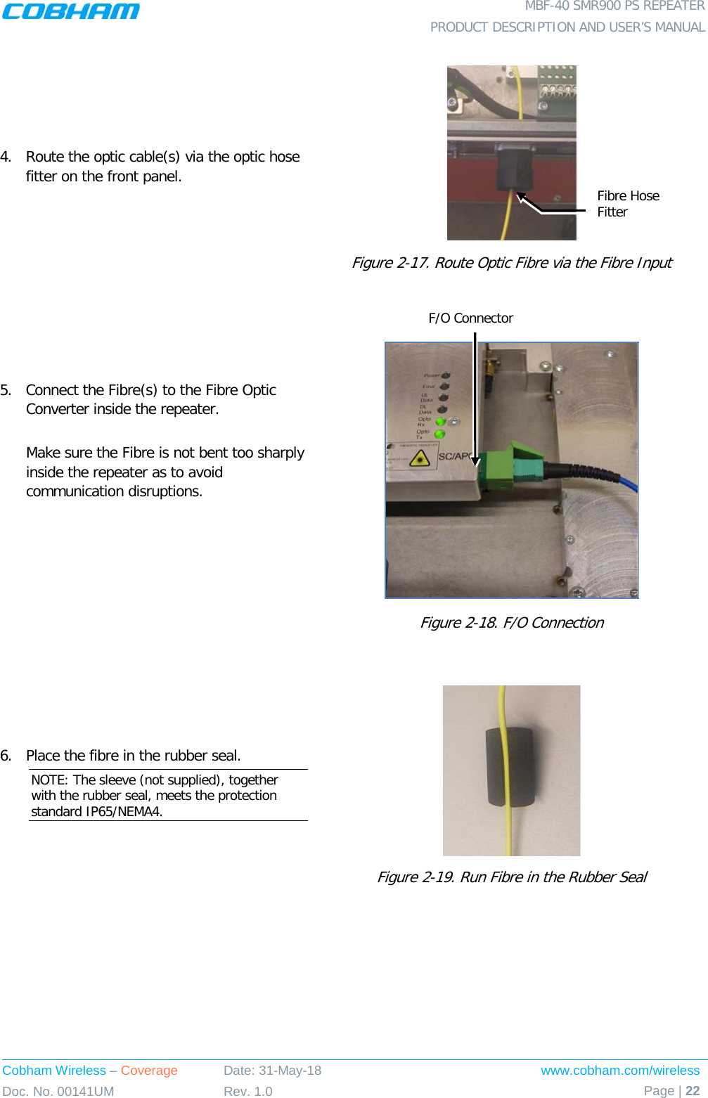
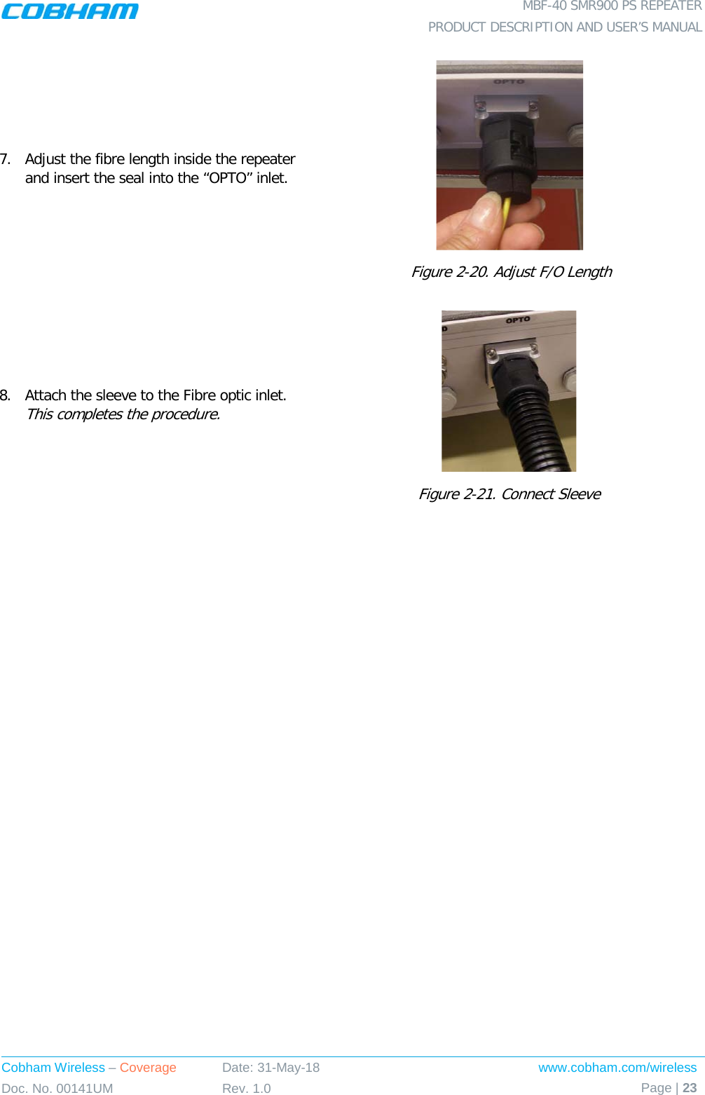
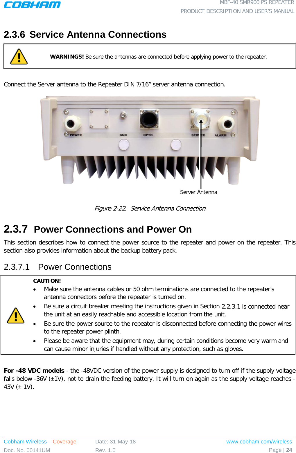
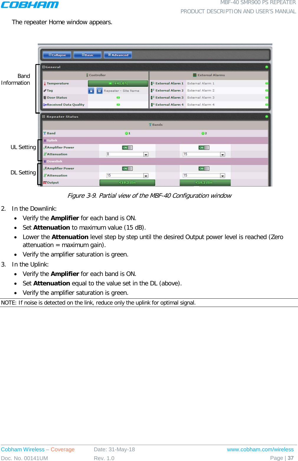
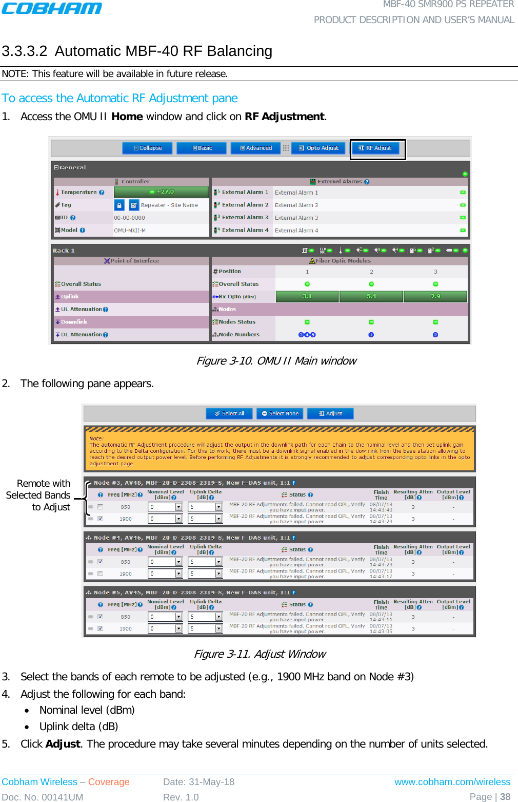
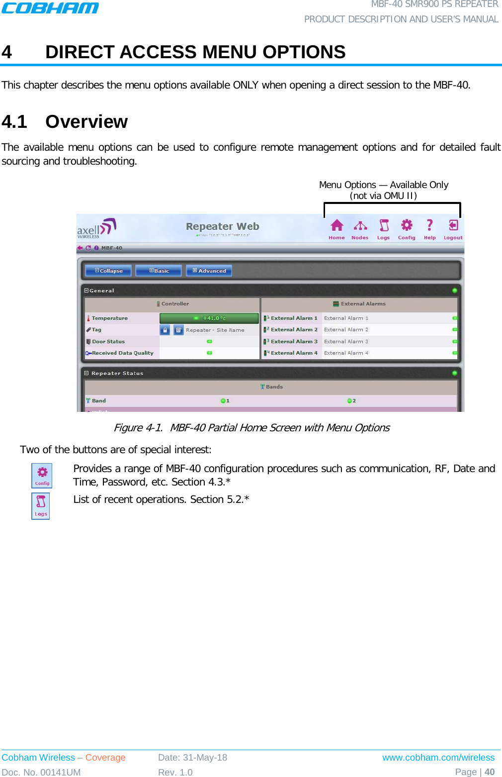
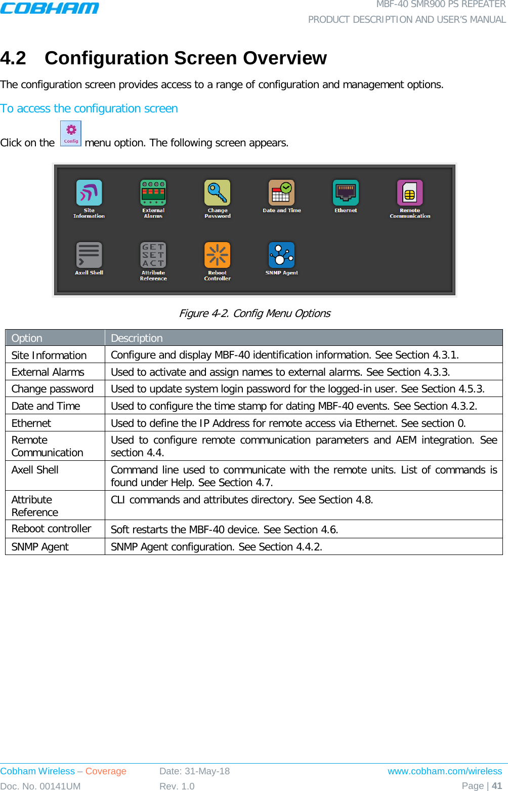
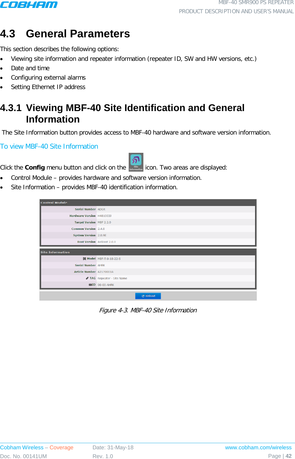
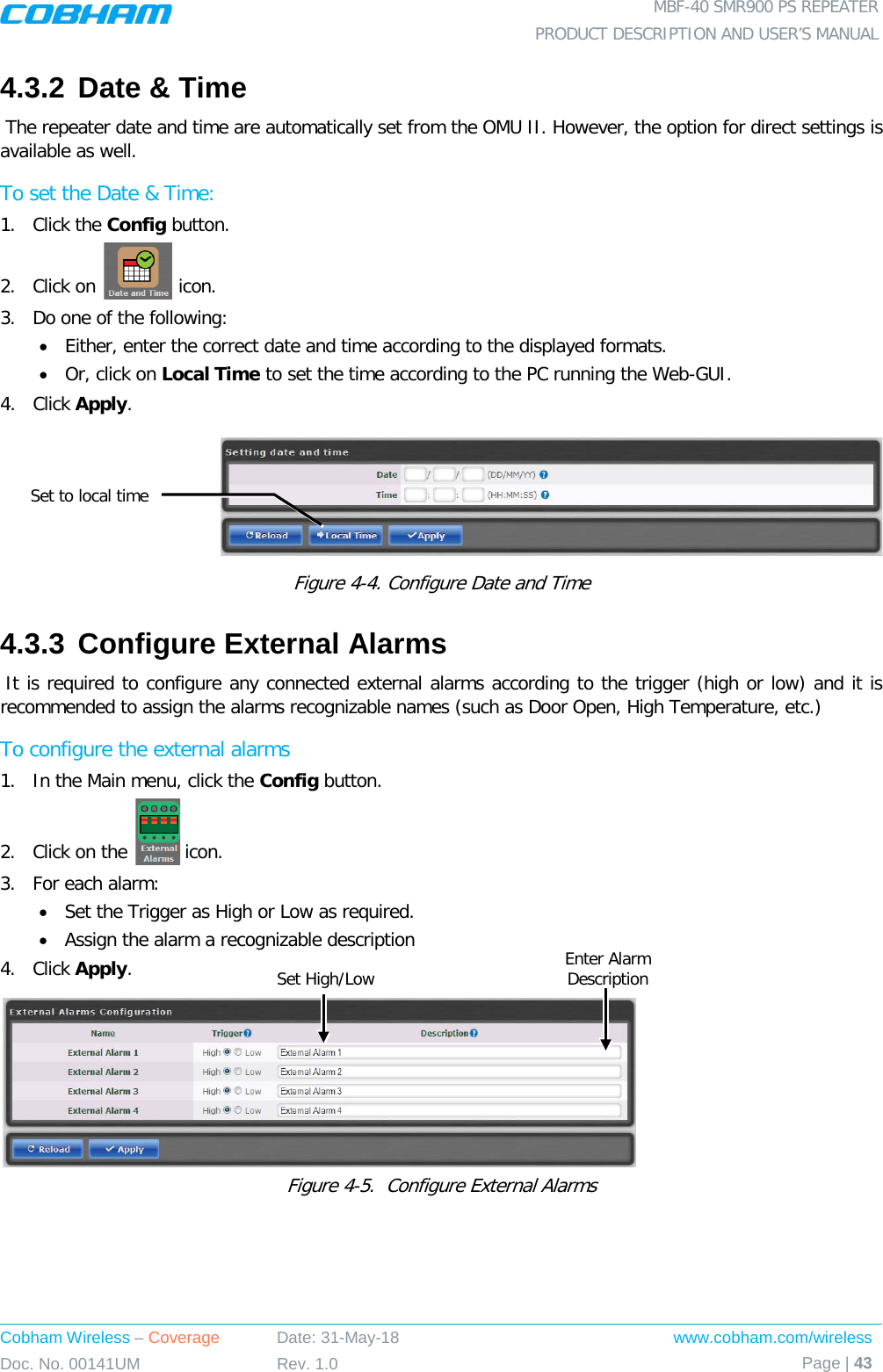
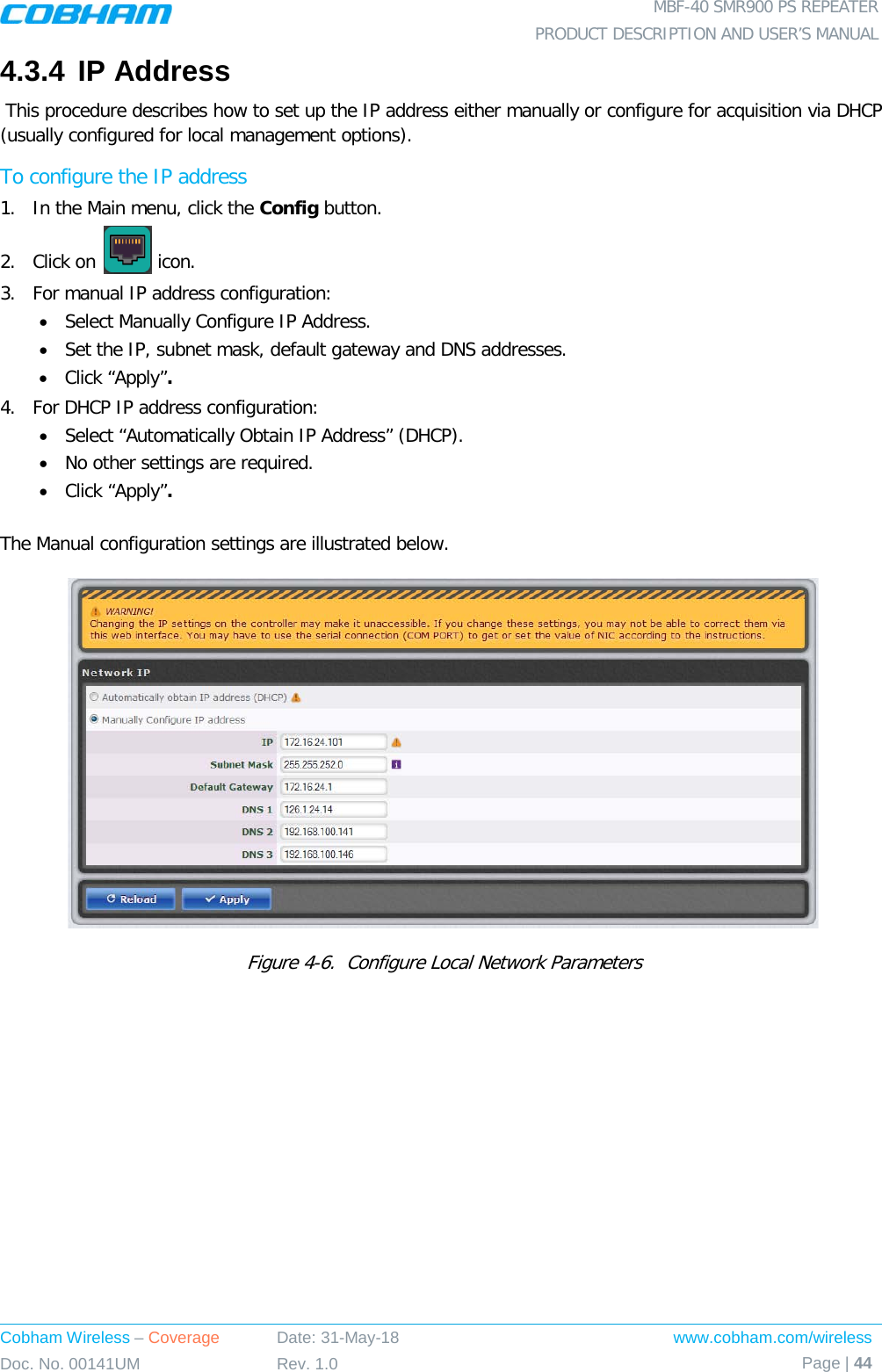
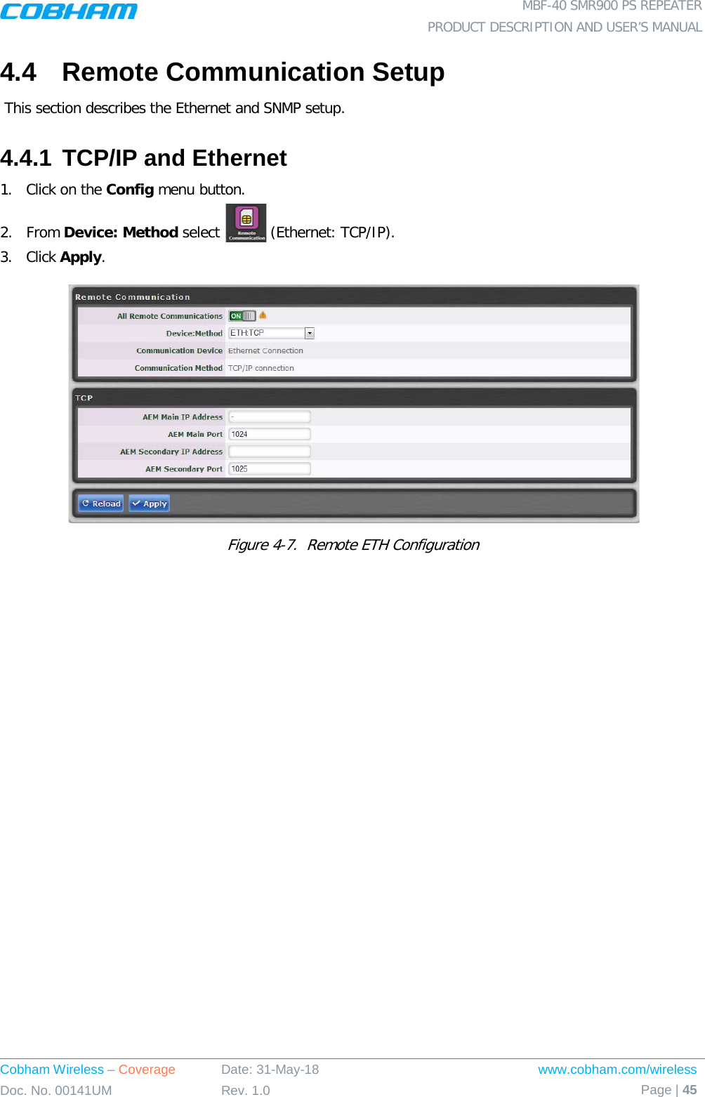
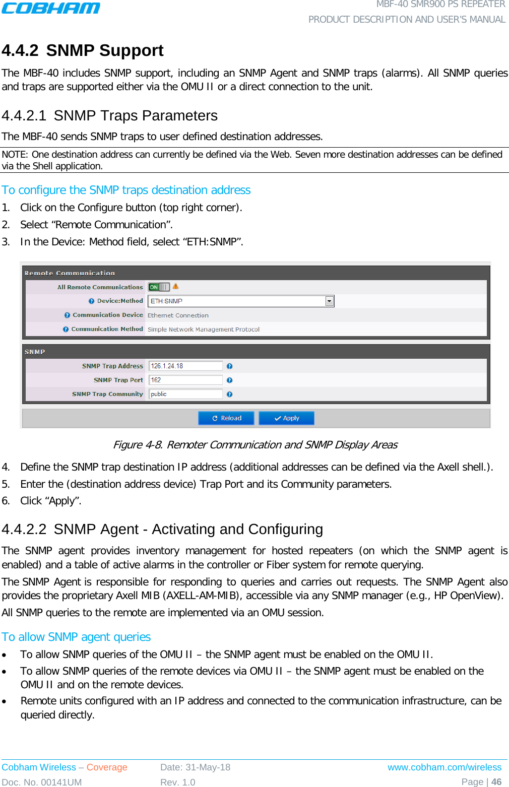
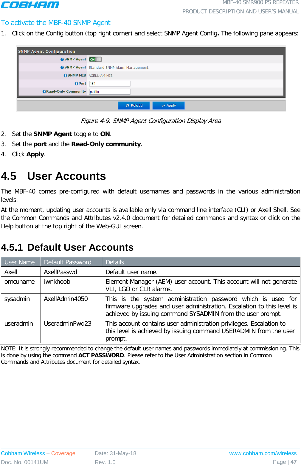
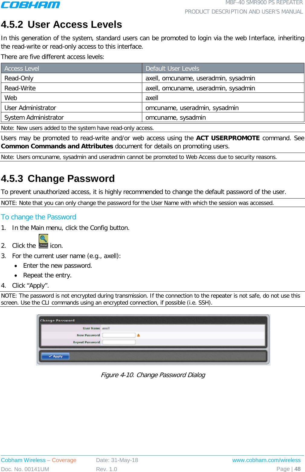
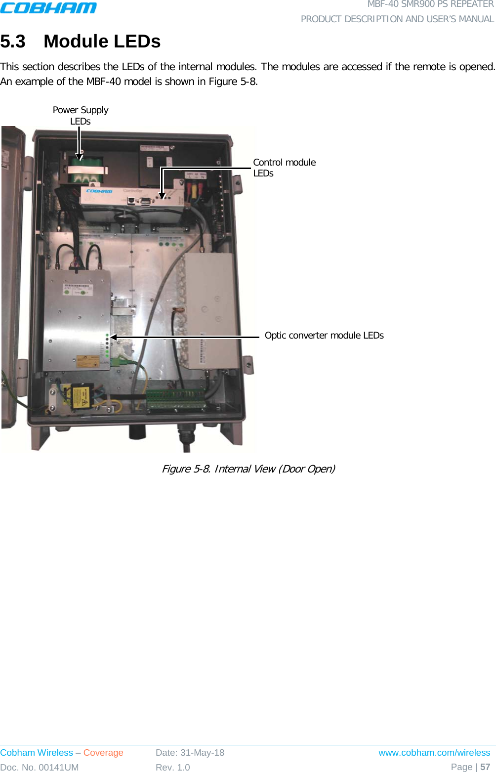
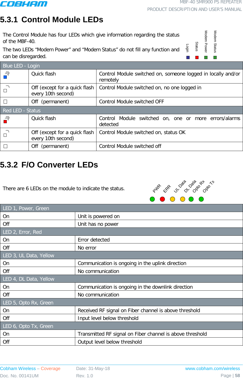
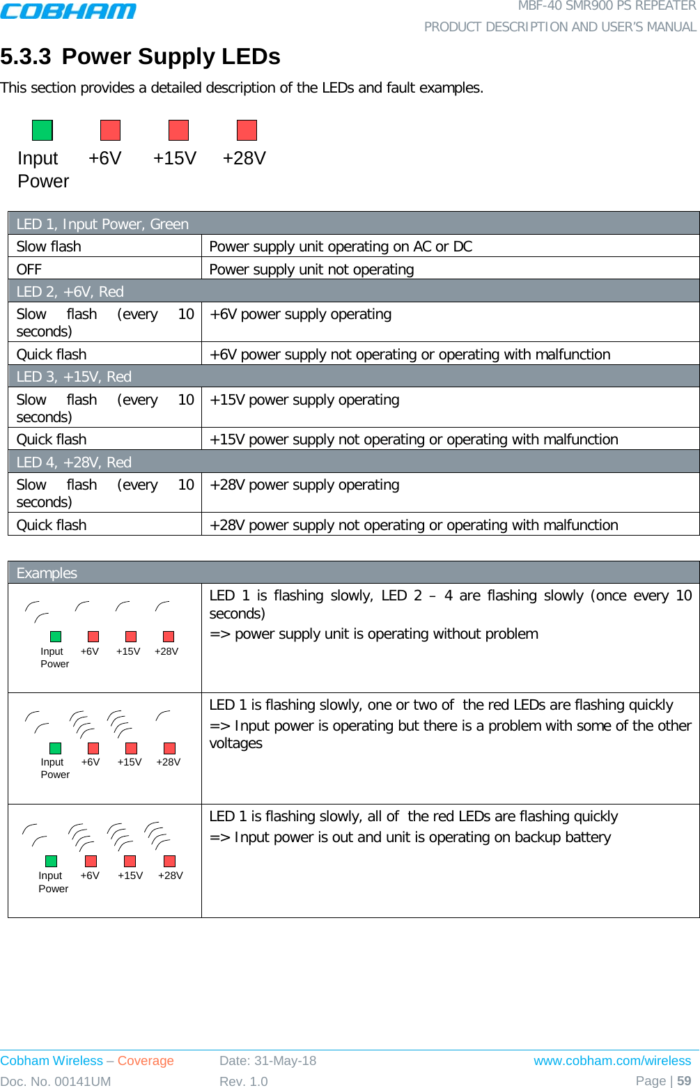
![MBF-40 SMR900 PS REPEATER PRODUCT DESCRIPTION AND USER’S MANUAL Cobham Wireless – Coverage Date: 31-May-18 www.cobham.com/wireless Doc. No. 00141UM Rev. 1.0 Page | 12 2.3 Repeater Installation 2.3.1 Unpacking Upon receiving the MBF-40 Repeater perform the following: 1. Examine the shipping container for damage before unpacking the unit. 2. Perform a visual inspection to reveal any physical damage to the equipment. 3. Verify that all of the equipment (listed below) is included. Otherwise contact Cobham Wireless. The MBF-40 Repeater is shipped with the following equipment: Package Contents USB containing User’s Manual and USB driver Mounting Brackets Additional (supplied) installation components: Qty. Description 4x M8x12 bolts for securing the Repeater to the brackets 1x Insex tool for bolts 1x Power Cable 1x Fiber Conduit inlet hose fitter (may be pre-assembled) 2 x Sets of keys Optional equipment AC Cable [30 ft.] – Long cable for AC power Alarm Cable [30 ft.] – Long cable for External Alarms Input](https://usermanual.wiki/PBE-Europe-as-Axell-Wireless/MBF3709S/User-Guide-3884537-Page-24.png)