PBE Europe as Axell Wireless MBF3709S 900MHz Fibre fed Band Selective Booster User Manual
Axell Wireless 900MHz Fibre fed Band Selective Booster
User Manual
The most important thing we build is trust
MBF-40
SMR 900 PS Repeater
High Selectivity Digital Repeater
User Manual – 00141UM Rev. 1.0
THIS DOCUMENT IS VALID FOR THE MBF-40 HIGH SELECTIVITY DIGITAL REPEATER
SUPPORTING THE SMR900 BAND
MBF-40 SMR900 PS REPEATER
PRODUCT DESCRIPTION AND USER’S MANUAL
Cobham Wireless – Coverage Date: 31-May-18 www.cobham.com/wireless
Doc. No. 00141UM Rev. 1.0 Page | II
This document is valid for the following models:
Unit Description Part Number
MBF SMR 900 MBF SMR 900 37 dBm 110 VAC MBF-3709-PS-AC
MBF SMR 900
MBF SMR 900 37 dBm 48VDC
MBF-3709-PS-48 VDC
Copyright © 2018 Axell Wireless Limited trading as Cobham Wireless
All rights reserved.
No part of this document may be copied, distributed, transmitted, transcribed, stored in a retrieval system, or translated
into any human or computer language without the prior written permission of Axell Wireless Limited trading as Cobham
Wireless.
The manufacturer has made every effort to ensure that the instructions contained in this document are adequate and
free of errors and omissions. The manufacturer will, if necessary, explain issues which may not be covered by this
document. The manufacturer's liability for any errors in the document is limited to the correction of errors and the
aforementioned advisory services.
This document has been prepared to be used by professional and properly trained personnel, and the customer assumes
full responsibility when using them. The manufacturer welcomes customer comments as part of the process of continual
development and improvement of the documentation in the best way possible from the user's viewpoint. Please submit
your comments to the nearest Cobham Wireless sales representative.
Contact Information
Headquarters Axell Wireless trading as Cobham Wireless
Aerial House, Asheridge Road
Chesham, Buckinghamshire
HP5 2QD, United Kingdom
Tel: +44 1494 777000
Fax: +44 1494 777002
Commercial inquiries cw.coverage@cobham.com
Website www.cobham.com/wireless
Support issues cw.support@cobham.com
Technical Support Line, English speaking +44 1494 777 747

MBF-40 SMR900 PS REPEATER
PRODUCT DESCRIPTION AND USER’S MANUAL
Cobham Wireless – Coverage Date: 31-May-18 www.cobham.com/wireless
Doc. No. 00141UM Rev. 1.0 Page | III
About This Manual
This product manual provides the following information:
o Description of the repeater unit
o Procedures for setup, configuration and checking the proper operation of the MBF-40
o Maintenance and troubleshooting procedures
Intended Audience
This Product Manual is intended for experienced technicians and engineers. It is assumed that the customers installing,
operating, and maintaining Cobham Wireless Repeaters are familiar with the basic functionality of Repeaters.
Cobham Wireless states in the User Manual that only suitably qualified, professional people should undertake the
installation of the product.
By only using suitably qualified, professional personnel to install the device, installation of the antenna can be
maintained, ensuring compliance with FCC RF exposure requirements and FCC rule part §90.219(c) – Ensuring that a
Type B signal Booster does not exceed the 5 W ERP requirement.
Notice
Confidential - Authorized Customer Use
This document may be used in its complete form only and is solely for the use of Cobham Wireless employees and
authorized Cobham Wireless channels or customers. The material herein is proprietary to Cobham Wireless. Any
unauthorized reproduction, use or disclosure of any part thereof is strictly prohibited.
All trademarks and registered trademarks are the property of their respective owners.
Disclaimer of Liability
Contents herein are current as of the date of publication. Cobham Wireless reserves the right to change the contents
without prior notice. The information furnished by Cobham Wireless in this document is believed to be accurate and
reliable. However, Cobham Wireless assumes no responsibility for its use. In no event shall Cobham Wireless be liable
for any damage resulting from loss of data, loss of use, or loss of profits and Cobham Wireless further disclaims any and
all liability for indirect, incidental, special, consequential or other similes damages. This disclaimer of liability applies to all
products, publications and services during and after the warranty period.
Guarantees
• All antennas must be installed with lightning protection. Damage to power modules, as a result of lightning are not
covered by the warranty.
• Switching on AC or DC power prior to the connection of antenna cables is regarded as faulty installation procedure
and therefore not covered by the Cobham Wireless warranty.
• The repeater box should be closed using the two screws. The screws must be fully tightened. Failure to do so may
affect the IP65 compliancy and therefore any warranty.
Exclusive Remedies
The remedies provided herein are the Buyer’s sole and exclusive remedies. Cobham Wireless shall not be viable for any
direct, incidental, or consequential damages, whether based on contract, tort, or any legal theory.
System Operation
The input / output RF level power level monitoring windows are for indication only and should not be considered a
replacement for laboratory test equipment accuracy of measurement of actual signal levels. The error of measurement
will be high at low input levels.
MBF-40 SMR900 PS REPEATER
PRODUCT DESCRIPTION AND USER’S MANUAL
Cobham Wireless – Coverage Date: 31-May-18 www.cobham.com/wireless
Doc. No. 00141UM Rev. 1.0 Page | IV
System Maintenance
• In the event of a failure Cobham Wireless’s support service should be contacted for advice on a possible module
replacement or other action to be taken.
• If a shipment of a repeater back to Cobham Wireless is made within the period of guarantee the original packing
must be used.
• The system normally operates without any operator intervention or maintenance. If in the unlikely event of any unit
failure, the faulty repeater should be replaced. A failed unit can be removed and replaced with a spare while the rest
of the system (other repeaters) is still operating. However, the power supply of the failed repeater should be isolated
from the power before anything is replaced.
• Component Replacement - None of the modules in the repeater can be replaced without removing the repeater from
its mounting and opening the cover of the repeater.
• In the event of a malfunction in the system, the status of the antenna systems as well as the continuity of the
cabling should be checked before replacing any modules within the repeater.
Product Disposal
Product Disposal - Disposal of this product must be handled according to all national laws and regulations. For detailed
information regarding materials, please refer to Cobham Wireless.
System Batteries
The Repeater contains two types of batteries:
o A battery pack in the power supply unit, consisting of 8X NiMh batteries.
o A button cell CR1216 on the controller board.
CAUTION! Risk of explosion if battery is replaced by an incorrect type. Dispose of used batteries
according to local laws and instructions.
MBF-40 SMR900 PS REPEATER
PRODUCT DESCRIPTION AND USER’S MANUAL
Cobham Wireless – Coverage Date: 31-May-18 www.cobham.com/wireless
Doc. No. 00141UM Rev. 1.0 Page | V
Compliance with FCC
NOTE: This repeater can be operated as both a Part 20 and/or Part 90 Class B repeater.
WARNING: This product is a booster and it is the responsibility of the licensee / installer to select the
correct cabling and antennas for their particular deployment scenario.
Part 90 Signal boosters THIS IS A 90.219 CLASS B DEVICE
WARNING! This is NOT a CONSUMER device. This device is designed for installation by FCC LICENCEES and
QUALIFIED INSTALLERS. You must have an FCC LICENCE or express consent of an FCC Licensee to operate this
device. You MUST register Class B signal boosters (as defined in 47 CFR 90.219) online at www.fcc.gov/signal-
boosters/registration.
Unauthorized use may result in significant forfeiture penalties, including penalties in excess of $100,000 for each
continuing violation.
This repeater must be operated as a Part 90 Class B repeater. The installation procedure must result in the signal
booster complying with FCC requirements 90.219(d). In order to meet FCC requirements 90.219(d), it may be
necessary for the installer to reduce the UL and/or DL output power for certain installations.
Part 20 Signal boosters
WARNING! This is NOT a CONSUMER device. This device is designed for installation by FCC LICENCEES and
QUALIFIED INSTALLERS. You must have an FCC LICENCE or express consent of an FCC Licensee to operate this
device..
Unauthorized use may result in significant forfeiture penalties, including penalties in excess of $100,000 for each
continuing violation.
FCC Part 15
This device complies with part 15 of the FCC Rules. Operation is subject to the following two conditions:
A. This device may not cause harmful interference, and
B. This device must accept any interference received, including interference that may cause undesired operation.
This equipment has been tested and found to comply with the limits for a Class B device, pursuant to part 15 of the
FCC Rules. These limits are designed to provide reasonable protection against harmful interference when the equipment
is operated in a commercial environment. This equipment generates, uses, and can radiate radio frequency energy and,
if not installed and used in accordance with the instruction manual, may cause harmful interference to radio
communications. Operation of this equipment in a residential area is likely to cause harmful interference in which case
the user will be required to correct the interference at their own expense.
Unauthorized Changes to Equipment
Changes or Modifications not expressly approved by the manufacturer responsible for compliance could void the user’s
authority to operate the equipment.
In-building applications only
One must be aware that FCC regulation mandates that this repeater is to be used only
for in-building applications and
thus feed passive or active distributed antenna systems (DAS) accordingly.

MBF-40 SMR900 PS REPEATER
PRODUCT DESCRIPTION AND USER’S MANUAL
Cobham Wireless – Coverage Date: 31-May-18 www.cobham.com/wireless
Doc. No. 00141UM Rev. 1.0 Page | VI
FCC RF Exposure Limits
This unit complies with FCC RF exposure limits for an uncontrolled environment. This equipment must be installed and
operated with a minimum distance of 33 cm between the radiator and any person’s body.
Antenna Installation
Installation of an antenna must comply with the FCC RF exposure requirements. The antenna used for this booster must
be mounted on a permanent structure.
The FCC regulations mandate that the ERP of type B signal boosters should not exceed 5 W, this is equivalent to 8.2 W
EIRP.
Therefore the max antenna gain allowed for this type of signal booster should be limited to the values given by equation
1 (below) for the service antenna.
Equation (1) — Max SERVICE antenna gain
Maximum service antenna gain (dBi) = 39.1 – (37 dBm - # of antennas in dB – cable losses in dB).
For example:
No. of Antennas Cable Losses Max Allowed Antenna Gain
4 3 39.1 - (37-6-3) =11.1dBi
1 3 39.1- (37-0-3) = 5.1dbi
10 3 39.1- (37-10-3) = 15.1dbi
Compliance with FCC deployment rule regarding the radiation of noise and intermodulation
product
Good engineering practice must be used in regard to the signal booster’s radiation of intermodulation products and
noise. Thus, the gain of the signal booster should be set so that the ERP of the output of intermodulation products from
the signal booster should not exceed the level of -30 dBm in 10 kHz measurement bandwidth and noise from the signal
booster should not exceed the level of -43 dBm in 10 kHz measurement bandwidth.
In the event that the intermodulation or noise level measured exceeds the aforementioned values, the signal booster
gain should be decreased accordingly.
In general, the ERP of noise on a spectrum more than 1 MHz outside of the pass band should not exceed -70 dBm in a
10 kHz measurement bandwidth.
The MBF-900 repeater has a noise level of -43.8 dBm in 10 kHz measurement at 1 MHz spectrum outside the passband
of the signal booster, worst case intermodulation products at around -14.9 dBm in a 10 kHz bandwidth and an in-band
noise level at around -42.8 dBm in a 10 kHz bandwidth. Therefore, the noise or intermodulation product at the antenna
input port should be calculated based on equation (2).
Equation (2) — Input Noise or intermodulation product to service antenna
Input Noise to service antenna:
-XX dBm + Service Antenna gain – antenna splitter losses in dB – cable loss in dB
Example: Intermodulation product
Signal booster connected to 10 service antennas with a 100m long ½ inch cable.
Losses of such a cable with the connectors = ~ 12dB
Assuming 10 service antennas: antenna splitter losses = 11 dB
Based on equation (2) Input antenna noise (to the antenna) = -14.9-12 -11= -37.9 dBm ERP
The intermodulation product to the antenna should be -14.9 -12-11= -37.9dbm ERP

MBF-40 SMR900 PS REPEATER
PRODUCT DESCRIPTION AND USER’S MANUAL
Cobham Wireless – Coverage Date: 31-May-18 www.cobham.com/wireless
Doc. No. 00141UM Rev. 1.0 Page | VII
Example: In band Noise
Signal booster connected to 10 service antennas with a 100m long ½ inch cable.
Losses of such a cable with the connectors = ~ 12 dB
Assuming 10 service antennas: antenna splitter losses = 11 dB
Based on equation (2) Input antenna noise (to the antenna) = -42.8-12 -11=-65.8 dBm ERP
The in-band input noise to the antenna should be -42.8 -12-11= -65.8dbm ERP
Example: Out of band noise
Signal booster connected to 10 service antennas with a 100 m long ½ inch cable.
Losses of such a cable with the connectors = ~ 12 dB
Assuming 10 service antennas: antenna splitter losses = 11 dB
Based on equation (2) Input antenna noise (to the antenna) = -43.8 -12 -11= -66.8 dBm ERP
The out of-band input noise to the antenna should be -43.8 -12-11= -66.8 dbm ERP
NOTE: In this example there is a need to add an external band pass filter to attenuate the out of band noise by a further
3.2dB 1MHz away from the band edge. If fewer antennas are deployed then additional filtering will be required.
Conclusion:
Good engineering practice requires that in general when the out of band noise measured at the service antenna input is
more than -70 dBm per 10 kHz measurement bandwidth, an external band pass filter should be added to attenuate the
out of band noise level.
All Cobham Wireless repeaters include high selectivity duplexers and filters to attenuate the out of band noise. Should
additional filtering be required, we have a comprehensive range of interference filters which can be supplied upon
request.
MBF-40 SMR900 PS REPEATER
PRODUCT DESCRIPTION AND USER’S MANUAL
Cobham Wireless – Coverage Date: 31-May-18 www.cobham.com/wireless
Doc. No. 00141UM Rev. 1.0 Page | VIII
General Safety Warnings Concerning Use of System
Always observe standard safety precautions during installation, operation and maintenance of this product.
Caution labels!
Throughout this manual, there are "Caution" warnings. "Caution" calls attention to a
procedure or practice, which, if ignored, may result in injury or damage to the system,
system component or even the user. Do not perform any procedure preceded by a
"Caution" until the described conditions are fully understood and met.
Danger: Electrical Shock
To prevent electrical shock when installing or modifying the system power wiring,
disconnect the wiring at the power source before working with un insulated wires or
terminals.
Caution: Safety to personnel
o Before installing or replacing any of the equipment, the entire manual should be
read and understood.
o The user needs to supply the appropriate AC or DC power to the repeater.
Incorrect power settings can damage the repeater and may cause injury to the
user.
o Please be aware that the equipment may, during certain conditions become very
warm and can cause minor injuries if handled without any protection, such as
gloves.
Caution: RF Exposure
o RF radiation, arising from transmitter outputs connected to AWL’s equipment,
must be considered a safety hazard.
o This condition might only occur in the event of cable disconnection, or because a
‘spare’ output has been left un-terminated. Either of these conditions would impair
the system’s efficiency. No investigation should be carried out until all RF power
sources have been removed. This would always be a wise precaution, despite the
severe mismatch between the impedance of an N type connector at 50 ohm, and
that of free space at 377 ohm, which would severely compromise the efficient
radiation of RF power. Radio frequency burns could also be a hazard, if any RF
power carrying components were to be carelessly touched!
o Antenna positions should be chosen to comply with requirements (both local &
statutory) regarding exposure of personnel to RF radiation. When connected to an
antenna, the unit is capable of producing RF field strengths, which may exceed
guideline safe values especially if used with antennas having appreciable gain. In
this regard the use of directional antennas with backscreens and a strict site rule
that personnel must remain behind the screen while the RF power is on, is
strongly recommended.
o Where the equipment is used near power lines or in association with temporary
masts not having lightning protection, the use of a safety earth connected to the
case-earthing bolt is strongly advised.
Caution: Safety to
equipment
o When installing, replacing or using this product, observe all safety precautions
during handling and operation. Failure to comply with the following general safety
precautions and with specific precautions described elsewhere in this manual
violates the safety standards of the design, manufacture, and intended use of this
product.
o Changes or modifications not expressly approved by the party responsible for
compliance could void the user’s authority to operate the equipment.
o Cobham Wireless assumes no liability for the customer's failure to comply with
these precautions. This entire manual should be read and understood before
operating or maintaining the repeater.
Warning: Restricted Access
Location
Access to the unit installation location is restricted to service personnel who have been
instructed on the restrictions and the required precautions to be taken.
MBF-40 SMR900 PS REPEATER
PRODUCT DESCRIPTION AND USER’S MANUAL
Cobham Wireless – Coverage Date: 31-May-18 www.cobham.com/wireless
Doc. No. 00141UM Rev. 1.0 Page | IX
Attention: Electrostatic
Sensitivity
o Observe electrostatic precautionary procedures.
o ESD = Electrostatic Discharge Sensitive Device.
o Static electricity can be conducted to the semiconductor chip from the centre pin
of the RF input connector, and through the AC connector pins. When unpacking
and otherwise handling the repeater, follow ESD precautionary procedures
including use of grounded wrist straps, grounded workbench surfaces, and
grounded floor mats.
Caution: Class 1 Laser
The repeaters described in this manual are equipped with class 1 lasers, which have
been tested to meet IEC / EN 60825-1:2014 standards.
Caution - Un-terminated optical receptacles may emit laser radiation. Exercise caution
as follows:
o Use of controls or adjustments or performances of procedures other than those
specified herein may result in hazardous radiation exposure
o Do not stare into beam or view with optical instruments. Optical transmitters in
the fibre optic converter can send out high energy invisible laser radiation. There
is a risk for permanent damage to the eye.
o Always use protective cover on all cables and connectors which are not connected.
o Never look directly into a Fiber cable or a connector.
o Consider that a Fiber can carry transmission in both directions.
o During handling of laser cables or connections, ensure that the source is switched
off.
o Regard all open connectors with respect and direct them in a safe direction and
never towards a reflecting surface. Reflected laser radiation should be regarded as
equally hazardous as direct radiation.
Lifting and other Health and
Safety Recommendations
Certain items of Cobham Wireless equipment are heavy and care should be taken
when lifting them by hand. Ensure that a suitable number of personnel, appropriate
lifting apparatus and appropriate personal protective equipment is used especially
when installing Equipment above ground e.g. on a mast or pole and manual handling
precautions relevant to items of the weight of the equipment being worked on must be
observed at all times when handling, installing or dismounting this equipment.
Periodical Maintenance
In order to maintain proper cooling of the RRUs, is recommended to clean the fins of
the RRUs every two years using a damp cloth. If the RRU installation area is dusty or
dirty, it is recommended to perform this procedure more often.

MBF-40 SMR900 PS REPEATER
PRODUCT DESCRIPTION AND USER’S MANUAL
Cobham Wireless – Coverage Date: 31-May-18 www.cobham.com/wireless
Doc. No.: 000xxUM Rev. 1.0 Page | X
Table of Contents
1 INTRODUCTION ........................................................................................................................................... 1
1.1 Features and Capabilities ..................................................................................................................... 2
1.2 ALC ...................................................................................................................................................... 2
1.3 Operating Temperature......................................................................................................................... 3
1.4 MBF-40 Management Web GUI ............................................................................................................. 3
1.5 MBF-40 Basic Interfaces ....................................................................................................................... 3
1.5.1 External Interfaces ........................................................................................................ 4
1.5.2 Securing the Unit .......................................................................................................... 4
1.5.3 Internal Interfaces ......................................................................................................... 5
2 INSTALLATION REQUIREMENTS and PROCEDURE ..................................................................................... 6
2.1 Service Antenna Requirements ............................................................................................................ 6
2.1.1 Required Antenna Information ....................................................................................... 6
2.1.2 Recommended Antennas .............................................................................................. 6
2.1.3 Recommended Splitters and Couplers ........................................................................... 7
2.1.4 Indoor Installations Service/Mobile Antenna Requirements .............................................. 7
2.2 Infrastructure and Cabling Considerations ........................................................................................... 7
2.2.1 RF Cable Installation Guidelines .................................................................................... 8
2.2.2 Grounding Wires Requirements ..................................................................................... 8
2.2.3 Power Requirements..................................................................................................... 8
2.2.4 F/O Cable Installation Guidelines ................................................................................... 9
2.2.5 EMV Protection .......................................................................................................... 10
2.2.6 External Alarm and Relay Considerations ..................................................................... 11
2.2.7 Location Criteria ......................................................................................................... 11
2.3 Repeater Installation ......................................................................................................................... 12
2.3.1 Unpacking .................................................................................................................. 12
2.3.2 Rack Mount Installation ............................................................................................... 13
2.3.3 Wall Mount Installation ................................................................................................ 14
2.3.4 Grounding .................................................................................................................. 20
2.3.5 Fiber Optic Connection ................................................................................................ 21
2.3.6 Service Antenna Connections ...................................................................................... 24
2.3.7 Power Connections and Power On .............................................................................. 24
2.3.8 Optional - External Alarm and Relay Connections ......................................................... 28
2.3.9 Closing and Securing the Repeater .............................................................................. 29
3 GETTING STARTED .................................................................................................................................. 30
3.1 Opening a Repeater Session ............................................................................................................. 30
3.1.1 Opening a Direct Local Session ................................................................................... 30
3.1.2 Opening an Indirect Session (via the OMU II) ............................................................... 31
3.2 Navigating the Web Interface ............................................................................................................. 32
3.2.1 The Home Screen ....................................................................................................... 32
3.2.2 Menu Options Buttons ................................................................................................. 33
3.3 Commissioning the Repeater ............................................................................................................ 33
3.3.1 Defining Site Information – MBF-40 Identification .......................................................... 34
3.3.2 MBF-40 Optical Loss Adjustment (OLA) ....................................................................... 34
3.3.3 RF Balancing .............................................................................................................. 36
3.3.4 Integration into the AEM .............................................................................................. 39
3.3.5 What Next? ................................................................................................................ 39
4 DIRECT ACCESS MENU OPTIONS ............................................................................................................. 40
4.1 Overview ........................................................................................................................................... 40

MBF-40 SMR900 PS REPEATER
PRODUCT DESCRIPTION AND USER’S MANUAL
Cobham Wireless – Coverage Date: 31-May-18 www.cobham.com/wireless
Doc. No. 00141UM Rev. 1.0 Page | XI
4.2 Configuration Screen Overview ......................................................................................................... 41
4.3 General Parameters ........................................................................................................................... 42
4.3.1 Viewing MBF-40 Site Identification and General Information .......................................... 42
4.3.2 Date & Time ............................................................................................................... 43
4.3.3 Configure External Alarms ........................................................................................... 43
4.3.4 IP Address ................................................................................................................. 44
4.4 Remote Communication Setup .......................................................................................................... 45
4.4.1 TCP/IP and Ethernet ................................................................................................... 45
4.4.2 SNMP Support ........................................................................................................... 46
4.5 User Accounts ................................................................................................................................... 47
4.5.1 Default User Accounts ................................................................................................ 47
4.5.2 User Access Levels .................................................................................................... 48
4.5.3 Change Password ...................................................................................................... 48
4.6 Reboot .............................................................................................................................................. 49
4.7 Axell Shell (Command Line Interface) ................................................................................................ 49
4.8 Attribute Reference ........................................................................................................................... 50
5 MONITORING AND FAULT SOURCING ...................................................................................................... 51
5.1 Monitoring Via the MBF-40 Home Screen ........................................................................................... 52
5.1.1 General Page Area ..................................................................................................... 53
5.1.2 Detailed view of the MBF-40 ........................................................................................ 53
5.1.3 Detailed view of Fiber Optic Unit .................................................................................. 55
5.1.4 Subsystems ............................................................................................................... 55
5.2 Logs Screen ...................................................................................................................................... 56
5.3 Module LEDs ..................................................................................................................................... 57
5.3.1 Control Module LEDs .................................................................................................. 58
5.3.2 F/O Converter LEDs ................................................................................................... 58
5.3.3 Power Supply LEDs .................................................................................................... 59
6 MAINTENANCE ......................................................................................................................................... 60
6.1 Cautions and General Statements ..................................................................................................... 60
6.2 Batteries ............................................................................................................................................ 60
APPENDIX A – SPECIFICATIONS ...................................................................................................................... 61
APPENDIX B – F/O CLEANING PROCEDURE .................................................................................................... 62
MBF-40 SMR900 PS REPEATER
PRODUCT DESCRIPTION AND USER’S MANUAL
Cobham Wireless – Coverage Date: 31-May-18 www.cobham.com/wireless
Doc. No.: 000xxUM Rev. 1.0 Page | 1
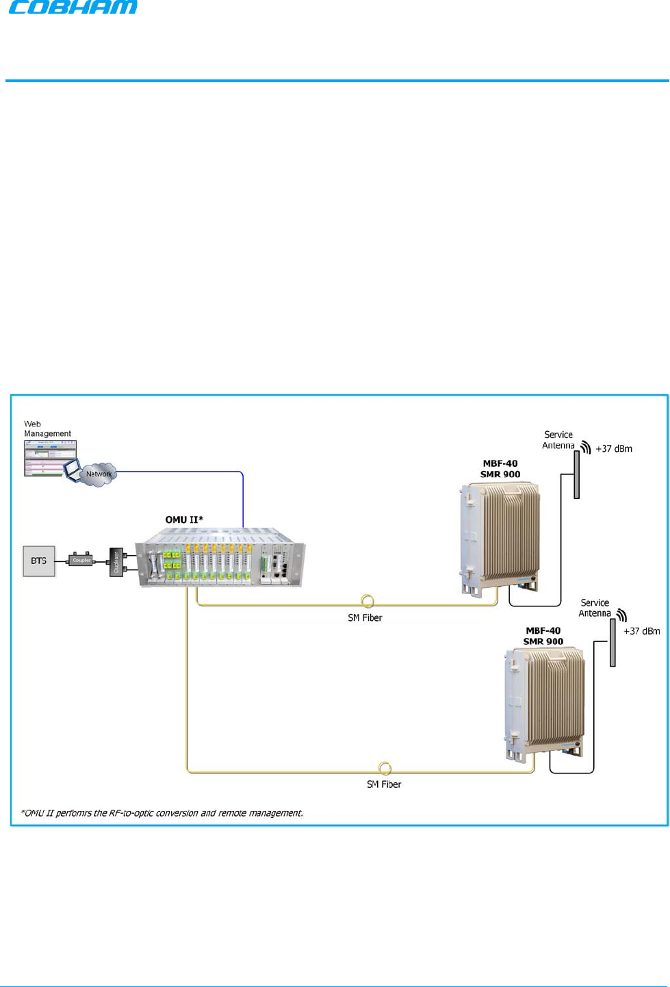
1 INTRODUCTION
MBF-40 SMR 900 repeater is an optic fed system that encapsulates solutions for single or multi-operator use.
It offers seamless coverage in any indoor environment such as tunnels, subways and large buildings. Signals
are coupled off from a nearby base station using an optical master unit (OMU) and then distributed via fiber
to one or more MBF-40 repeaters.
The MBF-40's high output power allows for greater coverage whilst deploying fewer units. Even though
providing high output power, the MBF-40 uses convection cooling, subsequently increasing the repeater's
MTBF.
These remote units can be installed at a distance of up to 20 km from the base station site, offering great
flexibility when providing RF coverage in areas where off air transmission is not a preferable solution.
A distributed antenna system (DAS) can be used to distribute the signal throughout the area to be covered.
Cobham Wireless can provide a complete solution including design, site surveys and equipment related to
the point of interface (POI) such as combiners, filters, cross band couplers, etc.
Figure 1-1. Illustration of a standard OMU II MBF Remote Application
MBF-40 SMR900 PS REPEATER
PRODUCT DESCRIPTION AND USER’S MANUAL
Cobham Wireless – Coverage Date: 31-May-18 www.cobham.com/wireless
Doc. No. 00141UM Rev. 1.0 Page | 2
1.1 Features and Capabilities
• High-power indoor unit supporting SMR 900 MHz
• Output power at the antenna (composite): 37 dBm
• Very low noise factor — minimizes interference to BTS and increases high speed data throughput
• Remote commissioning and monitoring:
• Via OMU II intuitive Web GUI
• SNMP v1/v2c support
• Plug-and-Play — automatic detection and optical gain setting via the OMU
• Automatic level control (ALC) — provides constant gain in both uplink and downlink paths according to
the defined maximum output level
• Backup battery for ‘last gasp’ indication (sending fault error before power failure)
• Power source: 115 VAC or -48 V power (model dependent)
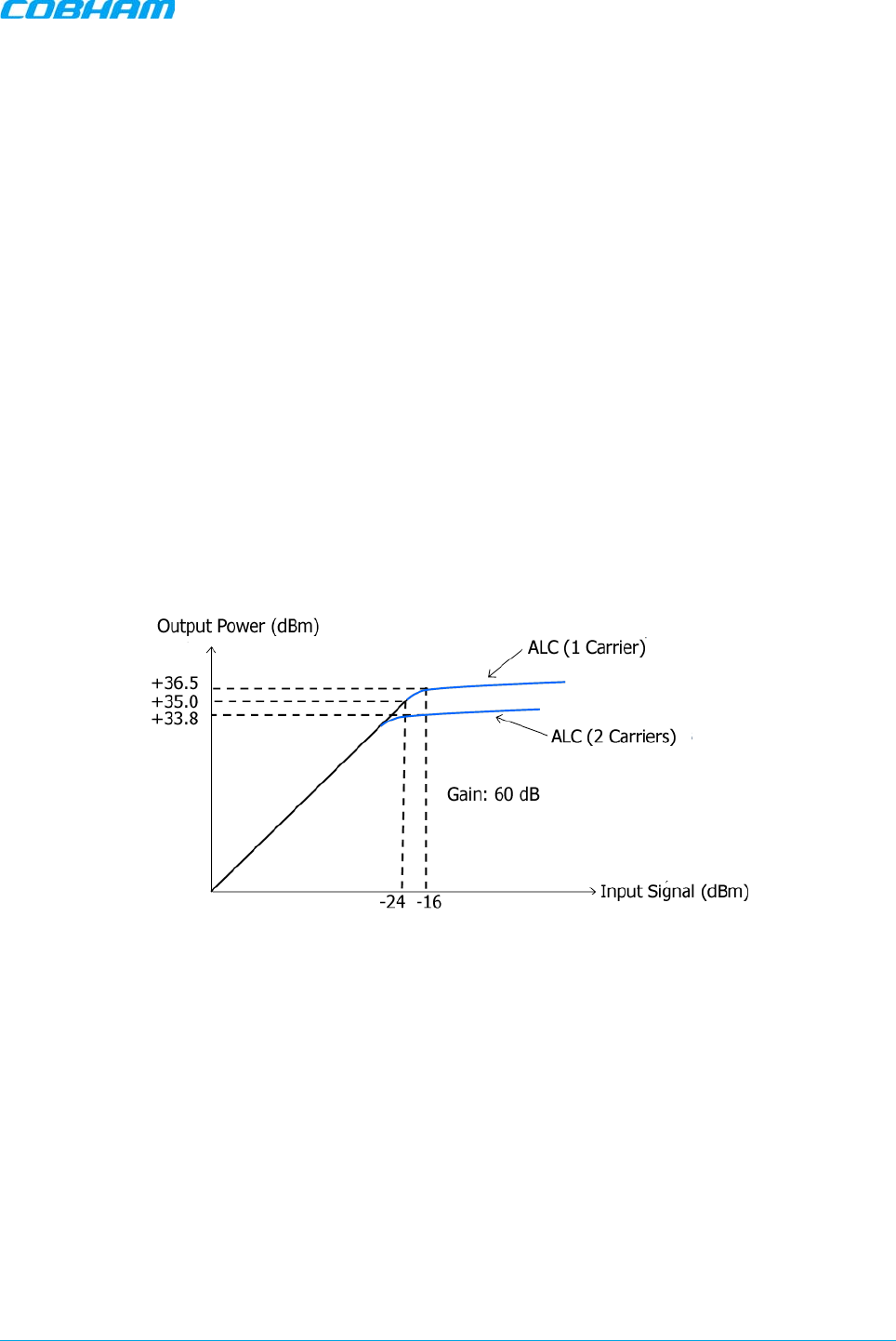
1.2 ALC
The repeater has a constant gain in both uplink and downlink paths. The repeater has a defined maximum
output level. If the input signal amplified by the gain set exceeds the set output limit, an automatic level
control (ALC) loop is activated. This ALC ensures that the amplifier does not add distortion to the radio
signal. Below are examples of the ALC function for one and two carriers.
Figure 1-2. Example of ALC for One and Two Carriers

MBF-40 SMR900 PS REPEATER
PRODUCT DESCRIPTION AND USER’S MANUAL
Cobham Wireless – Coverage Date: 31-May-18 www.cobham.com/wireless
Doc. No. 00141UM Rev. 1.0 Page | 3
1.3 Operating Temperature
The MBF-40 is designed primarily for multi carrier purposes. If the repeater is run at full output power over a
long period of time, additional, external cooling may be required; this can take the form of air-conditioning
or an external fan assembly.
NOTE: The repeater is equipped with a power management function that steps down the power and, if needed, fully
shuts down the amplifier chains until temperature reaches normal values.
1.4 MBF-40 Management Web GUI
MBF-40 is remotely commissioned and monitored via an OMUII session. Local access to the unit is not
required for commissioning.
Additional configuration and troubleshooting options are available via a direct connection to the MBF-40 IP
address. A direct session can be opened locally or remotely.
NOTE: Direct remote communication requires connecting the MBF-40 to an Ethernet network.
1.5 MBF-40 Basic Interfaces
The MBF unit provides several types of interfaces:
• Lock and screws for protection and security
• External service antenna and GND connections
• Internal connections for power, Fiber optics and alarm cables routed via openings in the front panel.
• Internal USB and Ethernet connections for local setup via web GUI
MBF-40 SMR900 PS REPEATER
PRODUCT DESCRIPTION AND USER’S MANUAL
Cobham Wireless – Coverage Date: 31-May-18 www.cobham.com/wireless
Doc. No. 00141UM Rev. 1.0 Page | 4
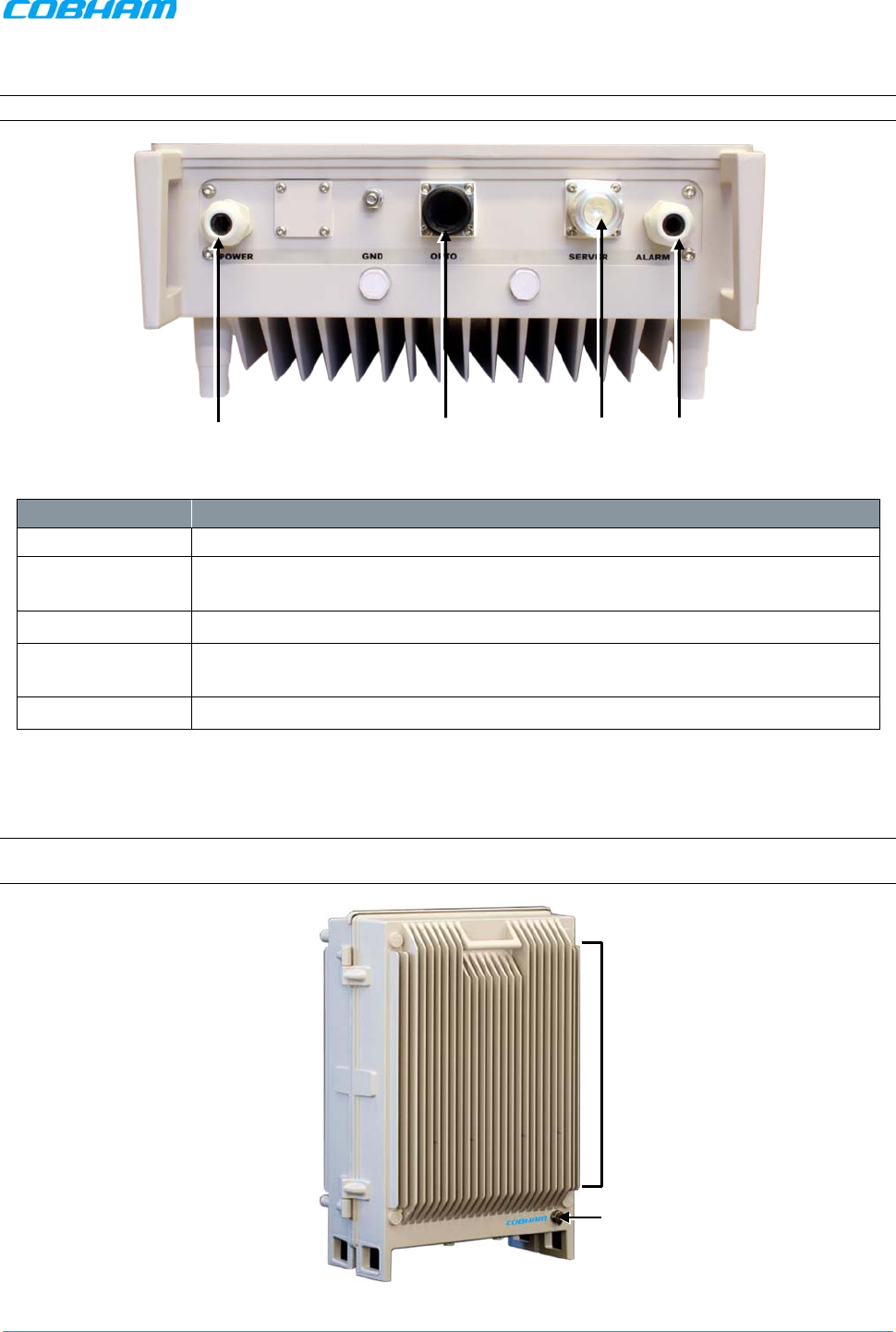
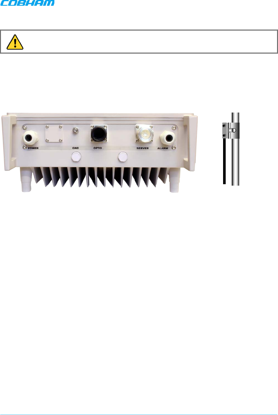
1.5.1 External Interfaces
NOTE: The external connections at the bottom of the repeater can be protected with a cover which is screwed in place.
Figure 1-3. External Interfaces
Port Description
Server Service antenna connection — DIN 7/16” connector, female
Optic SC/APC Fiber optic inlet through which the optic fibre
is routed for internal
connections (Section 2.3.5).
Power Plinth connection for routing power for internal connection (Section 2.3.7.1)
Alarms Plinth connector for routing external alarms and relay wiring cable for internal
connections (Section 0).
GND Grounding lug (Section 2.3.3)
1.5.2 Securing the Unit
The repeaters are secured with two hex screws (M8) and can also be locked with a key.
NOTE: The two screws must be fully tightened. Failure to do so may affect the IP65 compliancy and therefore any
warranty.
Figure 1-4. Securing Repeater
Lock
Fibre Input
Power Alarms
Server Antenna
Lock 2x Screws
Tightly

MBF-40 SMR900 PS REPEATER
PRODUCT DESCRIPTION AND USER’S MANUAL
Cobham Wireless – Coverage Date: 31-May-18 www.cobham.com/wireless
Doc. No. 00141UM Rev. 1.0 Page | 5
1.5.3 Internal Interfaces
This section shows the internal interfaces relevant to the following operations:
• Connect power
• Connect optic fibres
• Connect alarms (if relevant)
• Power-on (power-on switch)
• Optional — USB/Ethernet port for local setup
NOTE: The internal view of your repeater may be different, but the general location of the relevant items is the same.
Figure 1-5. MBF-40 SMR 900 — Internal View
Alarms and Relay Connections
USB Local Setup Connections
Ethernet Local Setup Port
Battery Pack
Control Module
Power and Battery Switches
Optic Converter Module
Optic Converter Module LEDs
Optic Fiber Connection
Power Connections
MBF-40 SMR900 PS REPEATER
PRODUCT DESCRIPTION AND USER’S MANUAL
Cobham Wireless – Coverage Date: 31-May-18 www.cobham.com/wireless
Doc. No. 00141UM Rev. 1.0 Page | 6
2 INSTALLATION REQUIREMENTS AND PROCEDURE
This chapter provides information on the service antenna requirements, general installation requirements
and the installation procedure.
2.1 Service Antenna Requirements
ATTENTION!
• The installer is held accountable for implementing the rules required for deployment.
• Good engineering practice must be used to avoid interference.
• Output power should be reduced to solve any IMD interference issues
This section provides information on the specifications of the service antennas suitable for operation with
this repeater, on the installation requirements of the antennas and on the Repeater installation site and
cable requirements.
2.1.1 Required Antenna Information
The following antenna requirements, specifications and site considerations should be met.
• Type of installation – indoor
• Service area type and size
• Antenna type and characteristics
• Height
• Length and type of coaxial cable required for connecting the Service antenna to the remote and the
attenuation.
2.1.2 Recommended Antennas
The Service antenna is installed indoors, where the type of antenna depends on the application.
Specifications:
• One or a combination of the following antennas can be used: Ceiling-mount patch antenna, wallmount
patch antenna, corner reflector.
• Choose an antenna with high side lobe attenuation which enables maximum isolation from other service/
mobile antennas.
Equation (1) — Max service antenna gain
Maximum service antenna gain (dBi) = 39.1 – (37 dBm - # of antennas in dB – cable losses in dB).
For example:
No. of Antennas Cable Losses Max Allowed Antenna Gain
4 3 39.1 - (37-6-3) =11.1dBi
1 3 39.1- (37-0-3) = 5.1dbi
10 3 39.1- (37-10-3) = 15.1dbi
MBF-40 SMR900 PS REPEATER
PRODUCT DESCRIPTION AND USER’S MANUAL
Cobham Wireless – Coverage Date: 31-May-18 www.cobham.com/wireless
Doc. No. 00141UM Rev. 1.0 Page | 7
Typical antenna types:
• Indoor dome 2.1 dBi; beam width 360°
• Indoor panel 4.2 dBi; beam width 106°
• Radiating cable typically < -50 dBi
2.1.3 Recommended Splitters and Couplers
Recommended Splitters
Splitter part numbers 90 - 851102 90 - 851103 90 – 851104
Frequency band 700 – 2700 MHz 700 – 2700 MHz 700 – 2700 MHz
Split 2 way 3 way 4 way
Max Insertion Loss 0.4 dB 0.6 dB 0.6 dB
Split Loss 3 dB 4.8 dB 6 dB
Recommended Couplers
Coupler part numbers 90 - 852206 90 - 852210 90 – 852215 90 – 852220
Frequency band 700-2700 MHz 700–2700 MHz 700–2700 MHz 700–2700 MHz
Coupling -6 dB ±0.8 dB -10 dB ±1.0 dB -15 dB ±1.0 dB -20 dB ±1.0 dB
Max Mainline Loss 1.7 dB 0.8 dB 0.4 dB 0.22 dB
2.1.4 Indoor Installations Service/Mobile Antenna
Requirements
Determine the antenna installation configuration, according to the transmission requirements and the
installation site conditions.
Installation requirements:
• An indoor antenna should be installed at a convenient location. It should be free of metallic obstruction.
• Install the service antenna at the designated height and tune it roughly toward the service coverage
area.
2.2 Infrastructure and Cabling Considerations
This section includes the following information:
• RF and grounding cabling guidelines
• Power requirements
• F/O installation guidelines
• EMV protection requirements
• External alarm and relay considerations
• Criteria for selecting the repeater location
MBF-40 SMR900 PS REPEATER
PRODUCT DESCRIPTION AND USER’S MANUAL
Cobham Wireless – Coverage Date: 31-May-18 www.cobham.com/wireless
Doc. No. 00141UM Rev. 1.0 Page | 8
2.2.1 RF Cable Installation Guidelines
• For all coaxial connections to/from the Repeater – use high performance, low-loss, 50 ohm coaxial
communication cables.
• All cables shall be weather-resistant type.
• Cable length – determined by the Repeater installation plan. When calculating the cable length, take into
account excess cable slack so as not to limit the insertion paths.
• Make sure the cable and the connector are compatible. Using cables and connectors from the same
manufacturer is helpful.
• All connectors must be clean and dry.
• Make sure enough room has been allocated for the bending radius of the cable. RF cables must not be
kinked, cut or damaged in any way.
• Connect the RF cable to the antenna tightly but without damaging threads.
• Fasten cable tightly to cable ladder or aluminium sheet.
• For short length feeder cables, use 1/2-in; for longer feeder cables, use 7/8-in. Choose thicker coax
cables for lower attenuation. Minimize the length of the coax cables to reduce attenuation.
• Use jumper cable for easy installation. The RF coaxial cable can be substituted at each end with a
jumper cable.
2.2.2 Grounding Wires Requirements
WARNING! Do not use the repeater grounding bolt to connect external devices.
Requirements for grounding wires
• Ensure that good grounding protection measures are taken to create a reliable repeater site.
• Make sure to use adequately dimensioned grounding cables. The minimum recommended conductive
area for a grounding cable is 16 mm2
• Make sure the grounding product used is suitable for the type and size of used cable.
• Connect the repeater box bolt to the same ground.
2.2.3 Power Requirements
This section describes the circuit breaker requirements and power cabling and connection considerations for
230 VAC power source and for -48 VDC power sources.
2.2.3.1 Circuit Breaker Requirements
The power connections to the unit are hard-wired. To disconnect the unit (either manually or automatically
in case of overcurrent), it is required to install a circuit breaker on the wall near the unit, at an easily
accessible distance and location from the unit.
Circuit-breaker minimum requirements
• 115 VAC — maximum current 10A
• Needs to be safety approved
• Use only a two-pole disconnect device.
• Requires minimum contact separation of 3mm.
• Install on the wall near the unit.
MBF-40 SMR900 PS REPEATER
PRODUCT DESCRIPTION AND USER’S MANUAL
Cobham Wireless – Coverage Date: 31-May-18 www.cobham.com/wireless
Doc. No. 00141UM Rev. 1.0 Page | 9
2.2.3.2 115 VAC Power Source Cable Requirements
Cable requirements:
• Cable should be NRTL (safety) approved with a minimum of 14 AWG or 2.5 mm² per conductor, and
maximum of 12 AWG or 4 mm² per conductor.
• For safety, the GND cable must be 10 mm longer than the phase and neutral cables.
2.2.3.3 -48 V Power Source Connection Requirements
NOTE: The -48 VDC version of the power supply is designed to turn off if the supply voltage falls below -36 V (±1V), not
to drain the feeding battery. It will turn on again as the supply voltage reaches -43 V (± 1V).
-48 V power supply requirements
The 48VDC power supply must comply with SELV requirements, as defined in EN60950, which implies
double isolation. The output power needs to be 48 VDC +25%/-15%. The maximum input current is 8 A.
Recommended cable areas for 48 VDC
Distance Cable Area
0-10 meters between repeater and power supply 2.5 mm²
10-50 meters between repeater and power supply 4 mm²
Over 50 mete
rs between repeater and power
supply Recommendation is to reconfigure the installation,
or to make special arrangements to increase cable
area
2.2.4 F/O Cable Installation Guidelines
This product is equipped with Class 1 Lasers, as per definition in EN 60825-1.
CAUTION!
Un-terminated optical receptacles may emit laser radiation.
Do not stare into beam or view with optical instruments.
WARNINGS!
o Maximum input power should not exceed (zero) 0 dBm
o Clean the fibre connectors (receptacles and cables) before connecting. See APPENDIX B – F/O
CLEANING PROCEDURE for details on F/O cleaning procedures.
Note the following:
• This procedure requires opening the repeater.
• Use angled APC connectors at 8 deg angle over the complete link between the Repeater and OMU
• Use APC type ODF connections
• Required Fibre cable: single mode 9/125
• Cable length — determined by the Remote installation plan. When calculating the cable length, take into
account excess cable slack so as not to limit the insertion paths.
MBF-40 SMR900 PS REPEATER
PRODUCT DESCRIPTION AND USER’S MANUAL
Cobham Wireless – Coverage Date: 31-May-18 www.cobham.com/wireless
Doc. No. 00141UM Rev. 1.0 Page | 10
2.2.5 EMV Protection
CAUTION! Ensure good EMV protection. If insufficient Electromagnetic Protection is provided, or if
EMV measures are not taken, warranties issued by Cobham Wireless are not valid.
Connect the lightning protection
The lightning hazard to electric and electronic equipment consists in the interferences of direct lightning
current infections and high surge voltages induced by the electromagnetic field of nearby lightning channels
or down conductors. Amplitudes from cloud-to-earth lightning amounts to several 10 kA and may last longer
than 2 ms. The damage caused depends on the energy involved and on the sensitivity of the electronics
systems.
Ensure that lightning protection measures are taken to
create a reliable repeater site. Protect all coaxial cables and
power cables from the transients caused by lightning. Fit all
cables with suitable lightning protection devices.
The primary protective device is part of the site installation
and is not supplied by Cobham Wireless. Coaxial lightning
protection is normally one of these three types: gas capsule,
high-pass and Bandpass.
There also need to be a protective device installed on the
power supply cord.
Several lightning protection devices should be used in series
with declining threshold voltages to help attenuate the pulse
component which makes it through
the first layer of
protection.
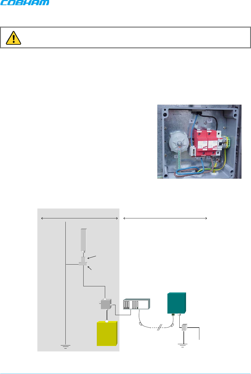
Figure
2-1. Protective Device Installed in
Connection with the Power Supply
Figure 2-2. Example of EMV protection for a repeater system
Repeater
Fiber
BTS
-30dB
Coupler
OMU
Antenna
Primary
Protective
Device
Equipotential
Grounding Bar
230VAC/
-48VDC
Protective
Device
The top of
the mast
must be
higher than
the antennas
and be
grounded
properly
The
grounding
path must
have reliable
continuity
and be
dimensioned
correctly
BTS area Repeater area

MBF-40 SMR900 PS REPEATER
PRODUCT DESCRIPTION AND USER’S MANUAL
Cobham Wireless – Coverage Date: 31-May-18 www.cobham.com/wireless
Doc. No. 00141UM Rev. 1.0 Page | 11
For detailed information please refer to IEC 61024-1 and 61312-1 for international standards for protection
of information systems against LEMP (Lightning Electromagnetic Pulse), including radio transmitters. They
define proper planning, installation and inspection of effective lightning protection systems.
Cobham Wireless repeaters comply with the EN standard ETS 301 498-8 which stipulates demands on
lightning/surge protection for typical infrastructure telecom equipment installations.
2.2.6 External Alarm and Relay Considerations
For installations that include connections of external alarms and relays
• The connector plinth for the external alarms is located inside the repeater.
• The strain relief fitting in is a Pg 13.5 suitable for a 6-12 mm cable diameter.
• Four external alarm sources can be connected to the repeater.
• Alarm operating voltage: between 12 and 24 VDC.
• The relay supplies 100mA maximum current
2.2.7 Location Criteria
Location criteria
• For wall mount installations:
• Wall compatibility - check the suitability of the wall on which the unit is to be to be fitted.
• Plan mount - check the actual fixing centers (see below) and overall dimensions of the unit
enclosure. The unit is supplied with two wall mounting brackets; when the unit is mounted on these
brackets adequate ventilation is provided between the unit and the wall to which it is fixed.
• Plan connection cable clearances — the optical, RF and power connections located on the underside
of the unit will need at least 300 mm vertical clearance below the unit to enable the connections to be
made. The minimum bend radius for optical and RF cables must not be less than the recommendations
made by the cable manufacturer. Plan the cable runs and ensure adequate space is available.
• Allow for door opening — ensure that there is sufficient space at the front of the unit to allow the
door to be fully opened and for maintenance engineers to get access to the unit with test equipment
such as a spectrum analyzer. Allow an additional 500 mm of space in front of the unit when the door is
fully open.
• Allow for heat dispersion — mount the repeater so that heat can be dispersed from it.
The repeater wall mounting kit ensures an optimum airflow between the wall and the repeater.) Do not
block this air channel as it will cause the MTBF of the repeater to drop dramatically, or even in the worst
case cause the repeater to fail completely.
MBF-40 SMR900 PS REPEATER
PRODUCT DESCRIPTION AND USER’S MANUAL
Cobham Wireless – Coverage Date: 31-May-18 www.cobham.com/wireless
Doc. No. 00141UM Rev. 1.0 Page | 12
2.3 Repeater Installation
2.3.1 Unpacking
Upon receiving the MBF-40 Repeater perform the following:
1. Examine the shipping container for damage before unpacking the unit.
2. Perform a visual inspection to reveal any physical damage to the equipment.
3. Verify that all of the equipment (listed below) is included. Otherwise contact Cobham Wireless.
The MBF-40 Repeater is shipped with the following equipment:
Package Contents
USB containing User’s
Manual and USB driver
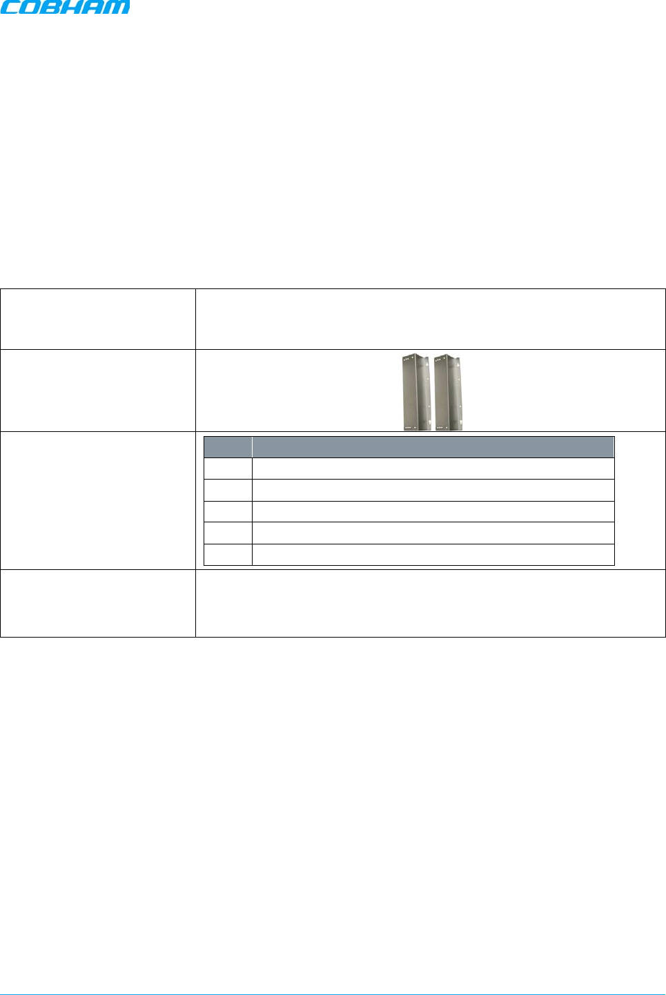
Mounting Brackets
Additional (supplied)
installation components:
Qty. Description
4x M8x12 bolts for securing the Repeater to the brackets
1x Insex tool for bolts
1x Power Cable
1x Fiber Conduit inlet hose fitter (may be pre-assembled)
2 x Sets of keys
Optional equipment AC Cable [30 ft.] – Long cable for AC power
Alarm Cable [30 ft.] – Long cable for External Alarms Input
MBF-40 SMR900 PS REPEATER
PRODUCT DESCRIPTION AND USER’S MANUAL
Cobham Wireless – Coverage Date: 31-May-18 www.cobham.com/wireless
Doc. No. 00141UM Rev. 1.0 Page | 13
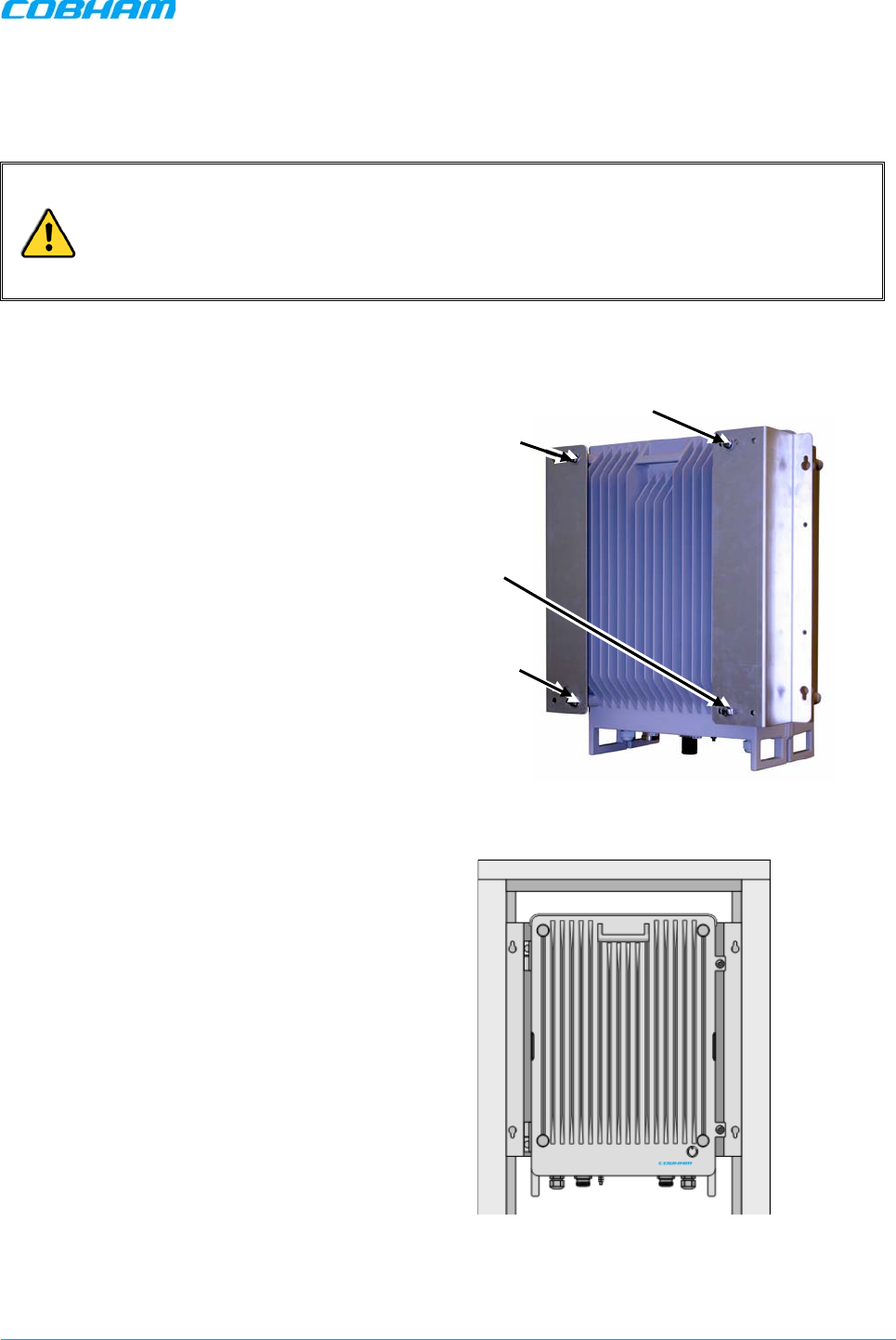
2.3.2 Rack Mount Installation
The supplied brackets are used to mount the repeater either on a wall or in a 19” rack. The same brackets
are used for both medium and high-power repeaters.
IMPORTANT!
• The weight of the unit requires that two people mount the unit onto the rack.
• The signal booster must always be installed vertically with the connectors on the
underside for protection. Horizontal installation on a bench for long time may cause
damage to the signal booster due to over-heating.
To mount the repeater in a rack
1. Use the x4 (provided) M8 fixing bolts and X4
spring washers to assemble the brackets as
illustrated below.
Figure
2-3. Rack-Mount Bracket Position
2. Mount the repeater vertically in the rack,
while adhering to standard rack mounting
procedures, and secure.
Figure
2-4. Rack-Mount Repeater Position
X4 M8 Bolts
x4 M8 Spring
Washers
MBF-40 SMR900 PS REPEATER
PRODUCT DESCRIPTION AND USER’S MANUAL
Cobham Wireless – Coverage Date: 31-May-18 www.cobham.com/wireless
Doc. No. 00141UM Rev. 1.0 Page | 14
2.3.3 Wall Mount Installation
IMPORTANT!
• The repeater mounting procedure is for concrete or brick walls only.
• The weight of the unit requires that two people mount the unit on the wall.
• The signal booster must always be installed vertically with the connectors on the underside for
protection. Horizontal installation on a bench for long time may cause damage to the signal
booster due to over-heating.
2.3.3.1 Wall Mount Bracket Assembly
NOTE: In addition to the mounting brackets, it is recommended to use additional fixings as described in Section 2.3.3.4.
To assemble the brackets
Assemble the brackets to the repeater using the supplied 4 x M8 bolts and spring washers as shown in the
following figure.
Figure 2-5. Position of Brackets for Wallmount
X4 M8 Bolts
X4 M8 Spring Washers
4 M8 Bolts
X4 M8 Spring Washers
MBF-40 SMR900 PS REPEATER
PRODUCT DESCRIPTION AND USER’S MANUAL
Cobham Wireless – Coverage Date: 31-May-18 www.cobham.com/wireless
Doc. No. 00141UM Rev. 1.0 Page | 15
2.3.3.2 Wall Marking and Drilling
WARNINGS!
• Due to the weight of the repeater, it is not recommended to fix to a hollow wall).
• The repeater wall mount brackets assembly should be fixed to a solid wall (these
include brickwork, block work, and concrete).
• Always check that there are no pipes or cables hidden in the wall beneath the area to
be drilled. Various pipe and cable detectors are available for this type of inspection.
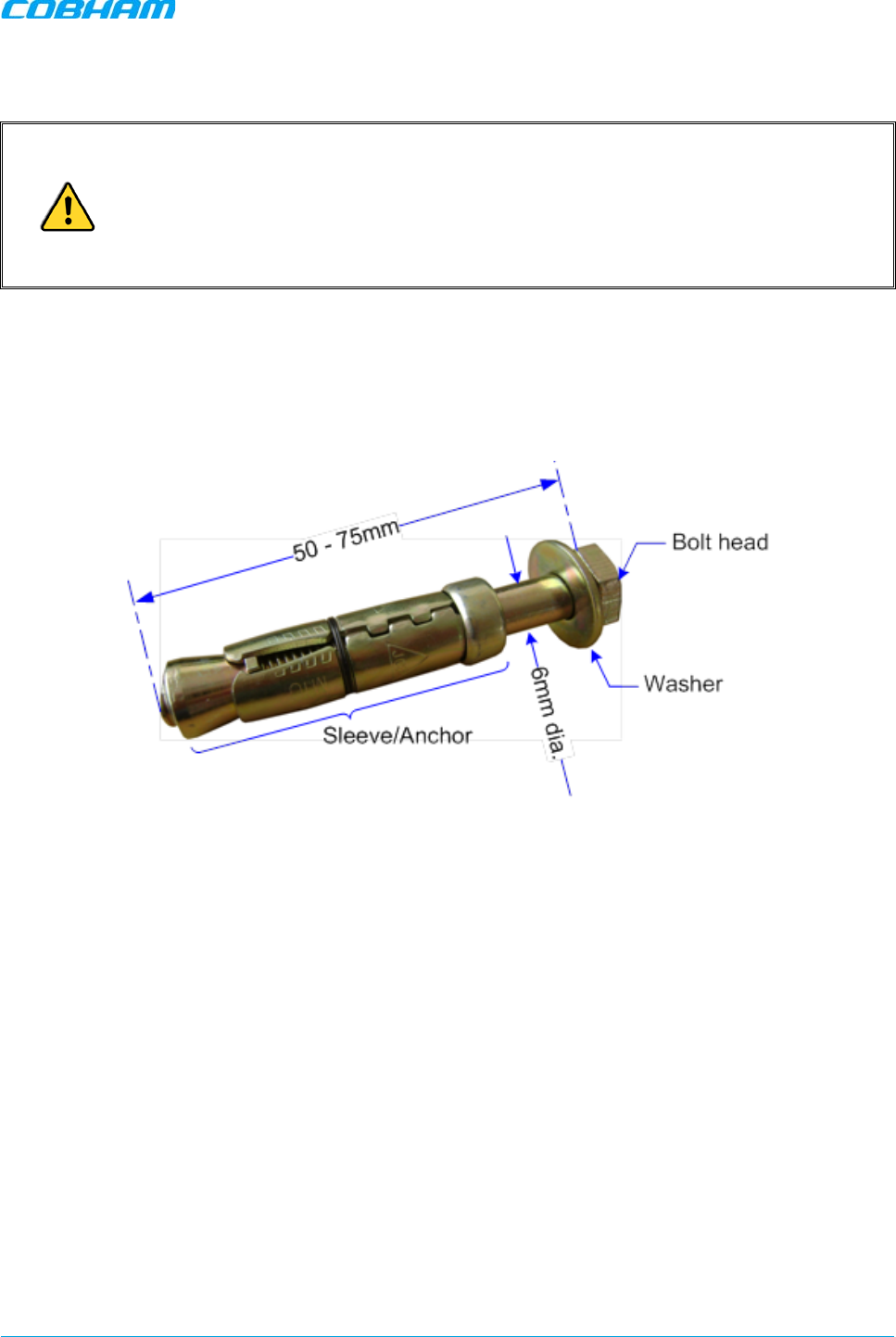
• To provide secure fixing to a solid wall, the most common method is drilling and plugging. The size of
fixing is dependent on the item to be fixed and the nature of the wall, The Repeater should be fixed with
mild steel, M6 (50 mm to 75 mm) rawlbolts or similar.
• Care must be taken to ensure the alignment of the four fixings. A spirit level or plumb line should be
used to ensure horizontal/vertical alignment.
Figure 2-6. M6 Rawlbolt — Recommended for Wallmount
MBF-40 SMR900 PS REPEATER
PRODUCT DESCRIPTION AND USER’S MANUAL
Cobham Wireless – Coverage Date: 31-May-18 www.cobham.com/wireless
Doc. No. 00141UM Rev. 1.0 Page | 16
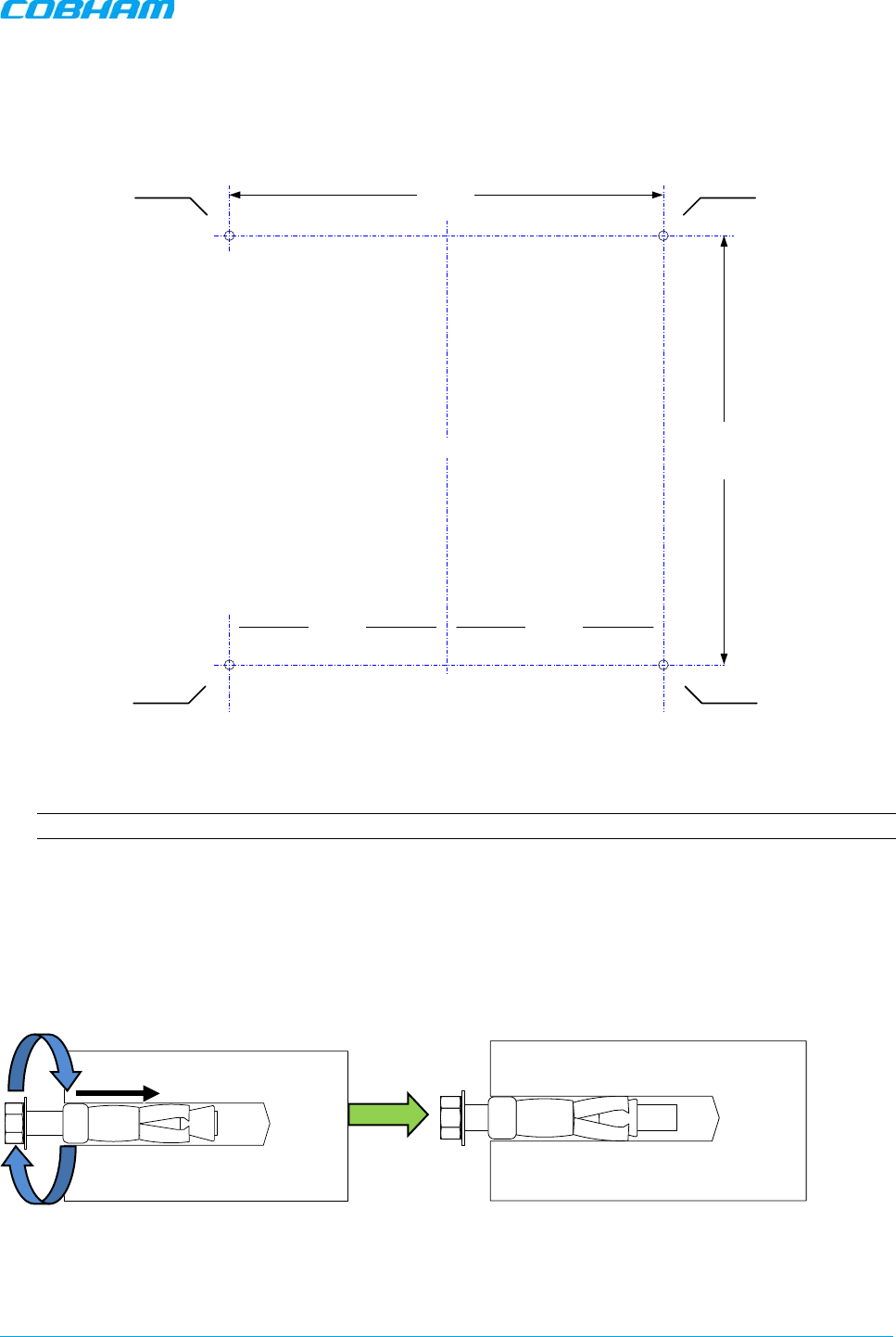
To mark and drill the wall
1. Using the provided
drill template
, mark out the fixing centers of the repeater on the chosen wall. The
repeater dimensions are shown below.
Figure 2-7. Fixing Centers
2. Mark and drill the wall with the correct size masonry bit as specified by the fixing manufacturer.
NOTE: It is good practice to wear goggles to protect your eyes from flying debris when using power tools.
3. Hold the drill bit against the mark and begin drilling slowly so that the bit does not wander from the
position. The wall should be drilled to a depth which is sufficient to accommodate the full length of the
fixing.
4. Insert the fixings so that the top of the sleeve/anchor section is level with the wall surface.
5. Gently tighten the bolt by hand so that the anchor section of the fixing expands and grips the inside of
the hole.
Figure 2-8. Inserting Fixing and Tightening
368mm
378mm
Hole to take
M6 rawl bolt
Hole to take
M6 rawl bolt
189mm 189mm
Centre Line of MBF
Hole to take
M6 rawl bolt
Hole to take
M6 rawl bolt
MBF-40 SMR900 PS REPEATER
PRODUCT DESCRIPTION AND USER’S MANUAL
Cobham Wireless – Coverage Date: 31-May-18 www.cobham.com/wireless
Doc. No. 00141UM Rev. 1.0 Page | 17
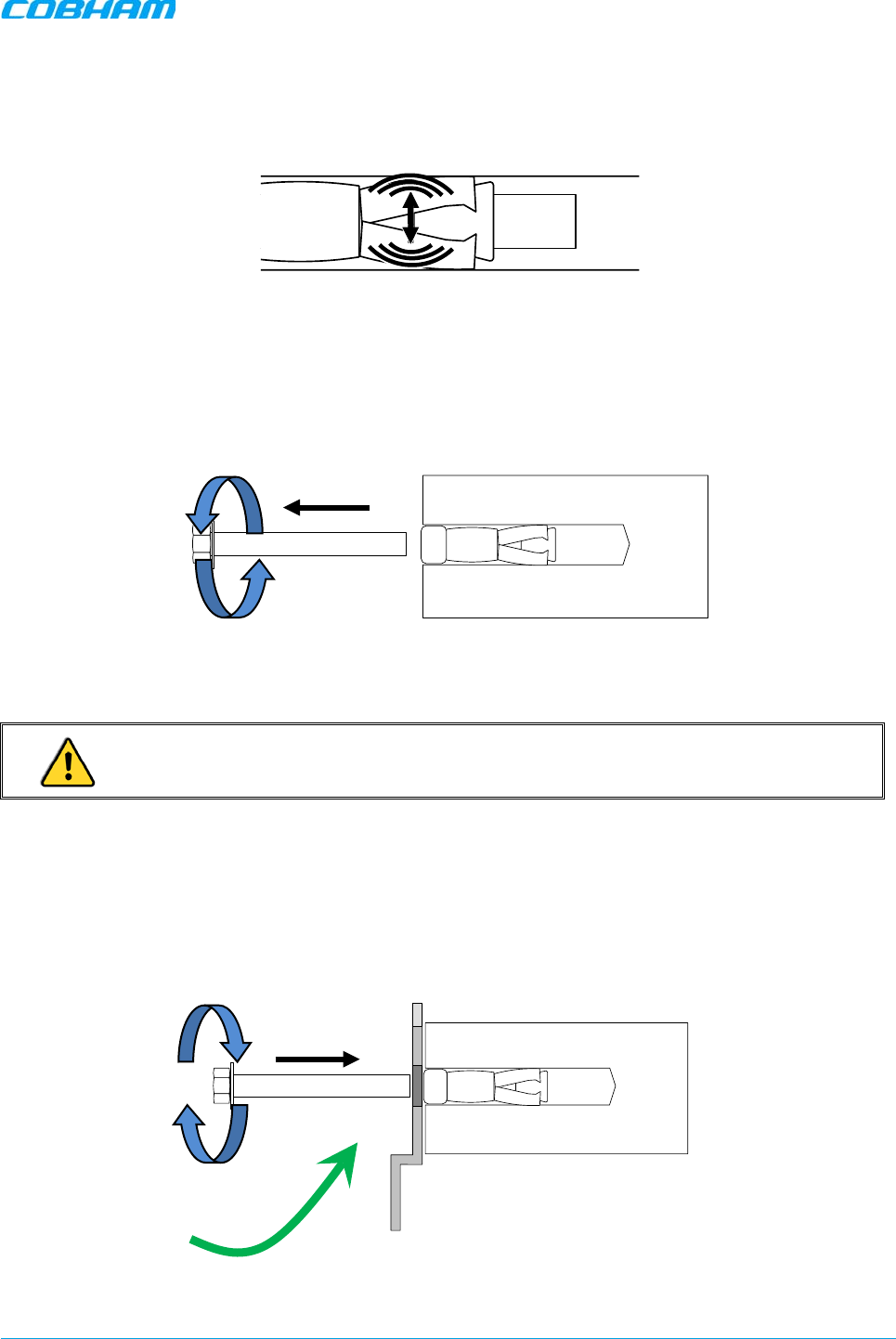
6. As the bolt pulls its way in, the sides of the anchor section are forced outwards, gripping the
surrounding surface.
Figure 2-9. Anchor Sides Pushed Outwards.
7. Once all four fixings are in place, carefully withdraw the four bolts.
Figure 2-10. Withdraw Bolts
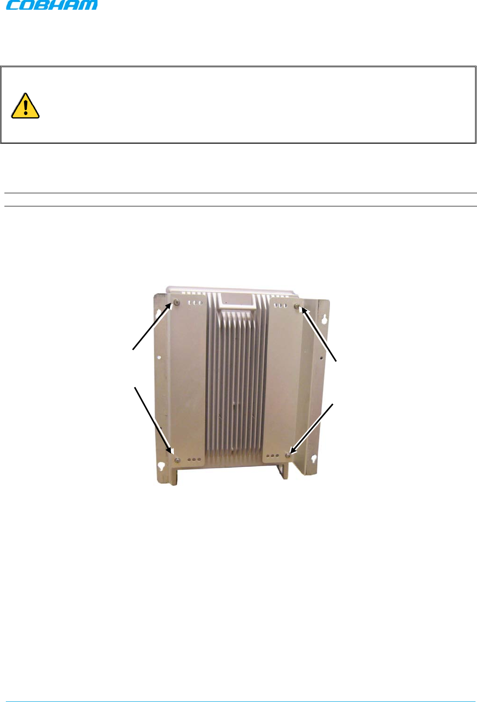
2.3.3.3 Mount the Repeater
CAUTION! It is recommended that two people lift the repeater since (depending upon the
configuration) the repeater weighs between 20 and 38 kg (44 and 84 lb)
To mount the repeater
• Align repeater with the four fixings. Great care should be exercised here as the repeater is very heavy.
(A suitably rated heavy duty scissor lift table/trolley may be suitable for this operation.)
• Once repeater is held in the chosen position, carefully insert the fixing bolts through the mounting lugs
of the Repeater and into the sleeve/anchor sections of the fixing in the wall and tighten the bolts.
• IMPORTANT! The repeater needs to be mounted tightly to eliminate vibration.
Figure 2-11. Mount Repeater
Align Repeater
and Secure Bolts
MBF-40 SMR900 PS REPEATER
PRODUCT DESCRIPTION AND USER’S MANUAL
Cobham Wireless – Coverage Date: 31-May-18 www.cobham.com/wireless
Doc. No. 00141UM Rev. 1.0 Page | 18
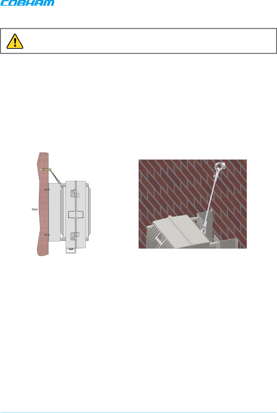
2.3.3.4 Recommended Additional Fixing
ATTENTION! It is the installer’s responsibility to ensure the repeater is installed in a secure manner.
Suggested precautionary measure:
• A bracket is provided to securely mount the repeater on the wall; however, as anadditional
precautionary measure, it is recommended to further secure the repeater to the wall (in addition to the
bracket).
• This can be done using any appropriate method.
The following figures provide examples of additional fixings. In the examples, support is provided in the form
of a cable harness loop that is looped around the repeater handle and secured to the wall or part of the
building support structure.
Figure 2-12. Example 1 – Additional Fixing to Wall
MBF-40 SMR900 PS REPEATER
PRODUCT DESCRIPTION AND USER’S MANUAL
Cobham Wireless – Coverage Date: 31-May-18 www.cobham.com/wireless
Doc. No. 00141UM Rev. 1.0 Page | 19
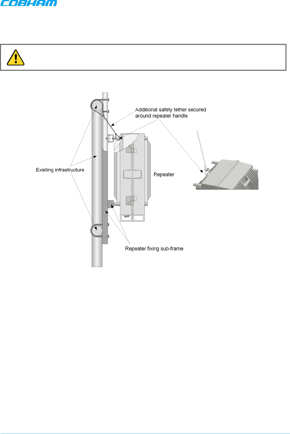
Another example is of a repeater installed on a stadium gantry. Again, the support can be in the form of a
cable harness loop, using the handle of the repeater and part of the gantry structure.
ATTENTION! Any other secure method can be used.
Figure 2-13. Example 2 – Additional Fixing to Gantry
MBF-40 SMR900 PS REPEATER
PRODUCT DESCRIPTION AND USER’S MANUAL
Cobham Wireless – Coverage Date: 31-May-18 www.cobham.com/wireless
Doc. No. 00141UM Rev. 1.0 Page | 20
2.3.4 Grounding
WARNING! Do not use the repeater grounding bolt to connect external devices.
To ground the repeater
• Refer to the grounding requirements described in Section 2.2.2.
• Connect the grounding protection to the repeaters ground lug.
Figure
2-14. Grounding the MBF-40
MBF-40 SMR900 PS REPEATER
PRODUCT DESCRIPTION AND USER’S MANUAL
Cobham Wireless – Coverage Date: 31-May-18 www.cobham.com/wireless
Doc. No. 00141UM Rev. 1.0 Page | 21
2.3.5 Fiber Optic Connection
This product is equipped with Class 1 Lasers, as per definition in EN 60825-1.
CAUTION!
o Un-terminated optical receptacles may emit laser radiation.
o Do not stare into beam or view with optical instruments.
WARNINGS!
o Maximum input power should not exceed (zero) 0 dBm
o Clean the Fibre connectors (receptacles and cables) before connecting. See APPENDIX B – F/O
CLEANING PROCEDURE for details on F/O cleaning procedures.
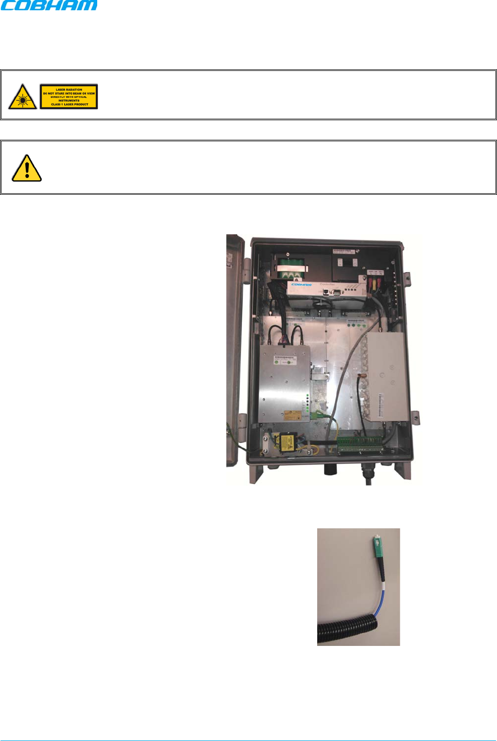
To connect the optic fibre
1. Refer to the optic fibre requirements and
connection guidelines described in section
2.2.4.
2. Open the repeater door.
Figure
2-15. Example of Open Repeater Model
3. Route the fibre through a corrugated
sleeve (not supplied).
Figure
2-16. Run Optic Fibres through Sleeve
MBF-40 SMR900 PS REPEATER
PRODUCT DESCRIPTION AND USER’S MANUAL
Cobham Wireless – Coverage Date: 31-May-18 www.cobham.com/wireless
Doc. No. 00141UM Rev. 1.0 Page | 22
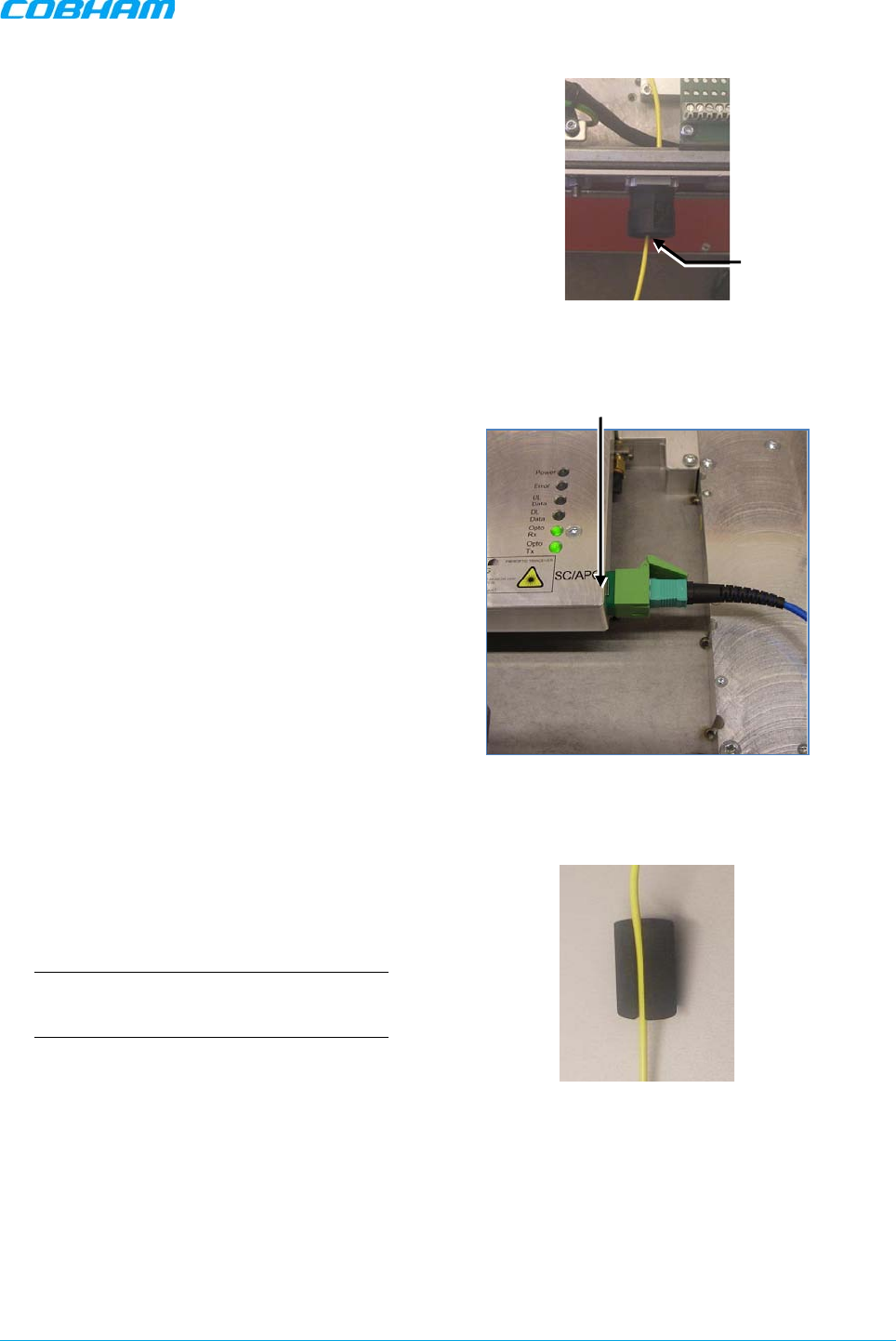
4. Route the optic cable(s) via the optic hose
fitter on the front panel.
Figure
2-17. Route Optic Fibre via the Fibre Input
5. Connect the Fibre(s) to the Fibre Optic
Converter inside the repeater.
Make sure the Fibre is not bent too sharply
inside the repeater as to avoid
communication disruptions.
Figure
2-18. F/O Connection
6. Place the fibre in the rubber seal.
NOTE: The sleeve (not supplied), together
with the rubber seal, meets the protection
standard IP65/NEMA4.
Figure
2-19. Run Fibre in the Rubber Seal
F/O Connector
Fibre Hose
Fitter
MBF-40 SMR900 PS REPEATER
PRODUCT DESCRIPTION AND USER’S MANUAL
Cobham Wireless – Coverage Date: 31-May-18 www.cobham.com/wireless
Doc. No. 00141UM Rev. 1.0 Page | 23
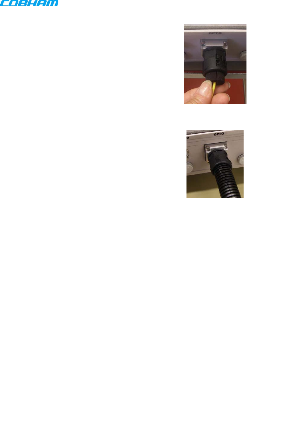
7. Adjust the fibre length inside the repeater
and insert the seal into the “OPTO” inlet.
Figure
2-20. Adjust F/O Length
8. Attach the sleeve to the Fibre optic inlet.
This completes the procedure.
Figure
2-21. Connect Sleeve
MBF-40 SMR900 PS REPEATER
PRODUCT DESCRIPTION AND USER’S MANUAL
Cobham Wireless – Coverage Date: 31-May-18 www.cobham.com/wireless
Doc. No. 00141UM Rev. 1.0 Page | 24
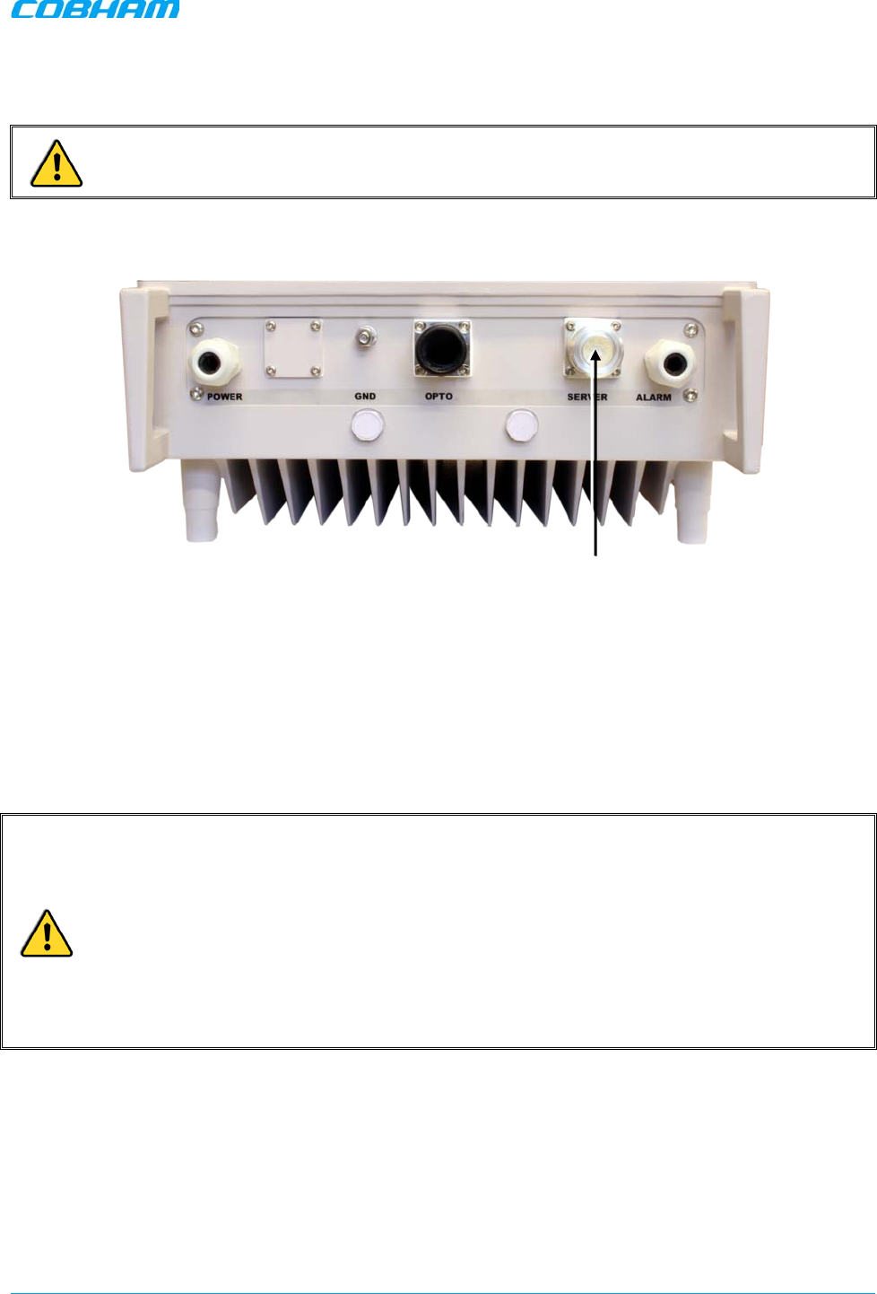
2.3.6 Service Antenna Connections
WARNINGS! Be sure the antennas are connected before applying power to the repeater.
Connect the Server antenna to the Repeater DIN 7/16” server antenna connection.
Figure 2-22. Service Antenna Connection
2.3.7 Power Connections and Power On
This section describes how to connect the power source to the repeater and power on the repeater. This
section also provides information about the backup battery pack.
2.3.7.1 Power Connections
CAUTION!
• Make sure the antenna cables or 50 ohm terminations are connected to the repeater’s
antenna connectors before the repeater is turned on.
• Be sure a circuit breaker meeting the instructions given in Section 2.2.3.1 is connected near
the unit at an easily reachable and accessible location from the unit.
• Be sure the power source to the repeater is disconnected before connecting the power wires
to the repeater power plinth.
• Please be aware that the equipment may, during certain conditions become very warm and
can cause minor injuries if handled without any protection, such as gloves.
For -48 VDC models - the -48VDC version of the power supply is designed to turn off if the supply voltage
falls below -36V (±1V), not to drain the feeding battery. It will turn on again as the supply voltage reaches -
43V (± 1V).
Server Antenna
MBF-40 SMR900 PS REPEATER
PRODUCT DESCRIPTION AND USER’S MANUAL
Cobham Wireless – Coverage Date: 31-May-18 www.cobham.com/wireless
Doc. No. 00141UM Rev. 1.0 Page | 25
To connect the power cables
1. Refer to the power requirements as described in Section 2.2.3.
2. Open the repeater door.
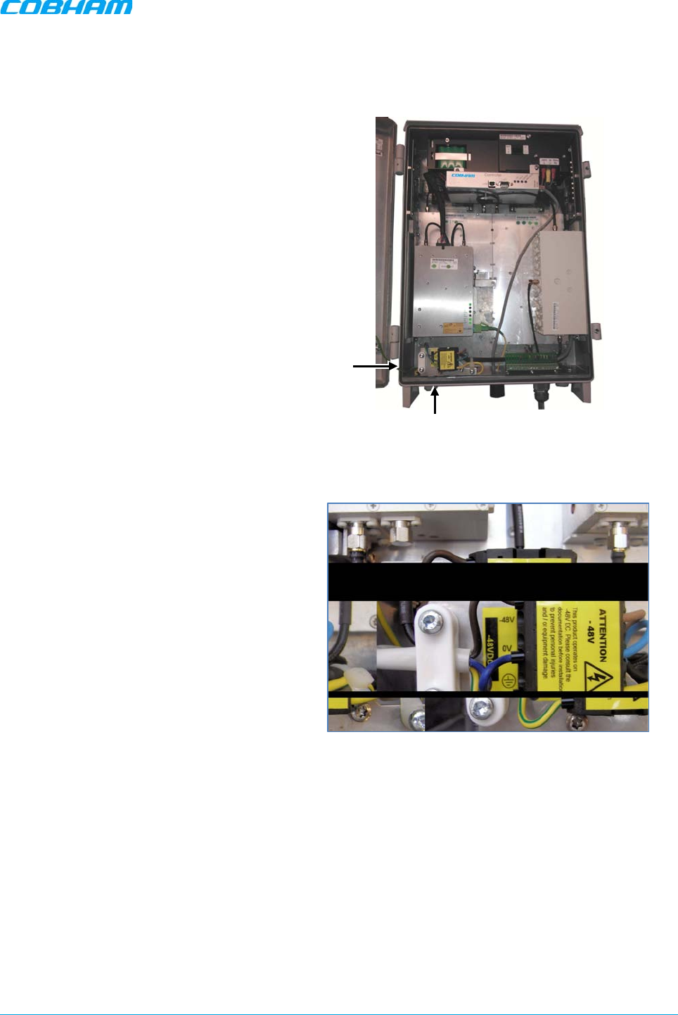
3. According to the repeater model, route the
power cable through the power interface
and towards the power plinth.
Figure
2-23. Example of MBF-40 Model
4. -48 VDC, connect wires to the plinth as
follows:
• Phase linked to brown cable
• Neutral linked to the blue
• Ground to the yellow/green.
Figure
2-24. -48 VDC Power Connections
Route Power Cable
through Front Panel
Connect Wires
to Plinth
MBF-40 SMR900 PS REPEATER
PRODUCT DESCRIPTION AND USER’S MANUAL
Cobham Wireless – Coverage Date: 31-May-18 www.cobham.com/wireless
Doc. No. 00141UM Rev. 1.0 Page | 26
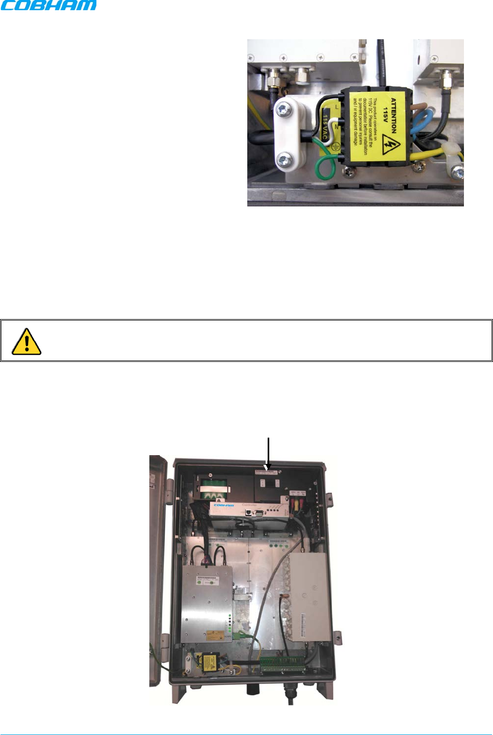
5. 115 VAC connect wires to the plinth as
follows:
• Phase linked to black cable
• Neutral linked to the white cable
• Ground to the green cable
Figure
2-25. 115VAC Power Connections
2.3.7.2 Power ON
The power supply has a switch which allows it to be set in two positions:
• ON – repeater is operational
• STAND-BY - the repeater is still connected to the power supply but not operational.
CAUTION! Make sure the antenna cables or 50 ohm terminations are connected to the repeater’s
antenna connectors before the repeater is turned on.
To power on the repeater
1. Locate the power supply switches inside the repeater.
Figure 2-26. Example of Single Power Supply Model
Power Supply
Switches
MBF-40 SMR900 PS REPEATER
PRODUCT DESCRIPTION AND USER’S MANUAL
Cobham Wireless – Coverage Date: 31-May-18 www.cobham.com/wireless
Doc. No. 00141UM Rev. 1.0 Page | 27
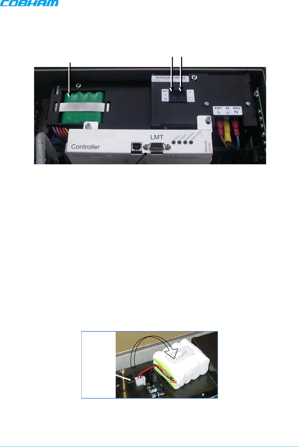
2. Switch on the power switch.
3. Switch on the BATT power.
Figure 2-27. Power and Battery Switches
4. Referring to Section 5.3, verify the LEDs from the following modules are indicating correct operation:
• Control module
• F/O converter(s)
• Power supply module(s)
2.3.7.3 About the Backup Battery
• On the Power Supply unit a rechargeable battery pack in mounted. This part also includes charging and
supervision electronics.
• The backup battery will provide the Control Module with enough capacity to send an alarm in case of
input power failure.
• The battery can be switched on and off. The switch is placed adjacent to the main power switch on the
power supply.
• At delivery the back-up battery is connected.
• The battery is replaced by lifting the battery pack out of the crate and disconnecting the cable.
Figure 2-28. Backup Battery
Connector
Backup
Battery Pack
Battery
ON/OFF
Power
ON/STANDBY
MBF-40 SMR900 PS REPEATER
PRODUCT DESCRIPTION AND USER’S MANUAL
Cobham Wireless – Coverage Date: 31-May-18 www.cobham.com/wireless
Doc. No. 00141UM Rev. 1.0 Page | 28
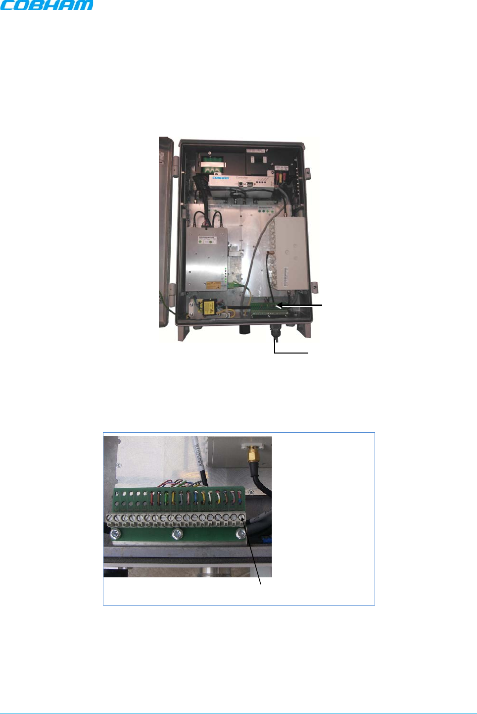
2.3.8 Optional - External Alarm and Relay Connections
The connector plinth for the external alarms is located inside the repeater.
To connect external alarms or relay
1. Refer to section 2.2.6 for the external alarms and relay considerations.
2. Locate the alarms plinth inside the repeater.
Figure 2-29. Example of Repeater Showing the Location of the Alarms Plinth
3. Connect the alarm cords to the plinth according to the pin layout below (in the standard version Pins 14–
18 are not used).
Figure 2-30. External Alarm and Relay Pinout
Note the following
• Four external alarm sources can be connected to the repeater:
• It is required to configure the external alarm polarity (part of the setup procedure — Section
4.3.3).
1External alarm 1A
2External alarm 1B
3External alarm 2A
4External alarm 2B
5External alarm 3A
6External alarm 3B
7External alarm 4A
8External alarm 4B
9Alarm +15V
10 Alarm 0V
11 Relay Output 1A
12 Relay Output 1B
13 GND
14 NC
15 NC
16 NC
17 NC
18 NC
Pin # Signal
Pin 1
Alarms Plinth
Route Alarms
Cable

MBF-40 SMR900 PS REPEATER
PRODUCT DESCRIPTION AND USER’S MANUAL
Cobham Wireless – Coverage Date: 31-May-18 www.cobham.com/wireless
Doc. No. 00141UM Rev. 1.0 Page | 29
• The repeater can supply +15 VDC to an external alarm source through Pins 9 and 10. The
maximum allowed load is 100 mA.
• Relay (Pins 11 and 12) can be connected to an external device to indicate an alarm.
The Relay Can be configured to trigger on any number of internal and external alarms. The maximum
current that can be supplied is 100 mA.
2.3.9 Closing and Securing the Repeater
The repeaters are secured with two hex screws (M8) and can also be locked with a key.
NOTE: The two screws must be fully tightened. Failure to do so may affect the IP65 compliancy and therefore any
warranty.
MBF-40 SMR900 PS REPEATER
PRODUCT DESCRIPTION AND USER’S MANUAL
Cobham Wireless – Coverage Date: 31-May-18 www.cobham.com/wireless
Doc. No. 00141UM Rev. 1.0 Page | 30
3 GETTING STARTED
This chapter includes the following information:
• Opening a repeater session
• Navigating the WEB GUI
• Initial setup procedure
3.1 Opening a Repeater Session
Two types of session can be opened to the repeater:
• Direct session – this is usually a direct local session to the repeater
• Remote session – this is usually done by opening a session to the OMU II and then connecting to the
repeater (via the OMU II)
3.1.1 Opening a Direct Local Session
NOTE: This connection requires downloading the USB driver from the provided setup disk (or connection to the internet,
where the driver is automatically loaded).
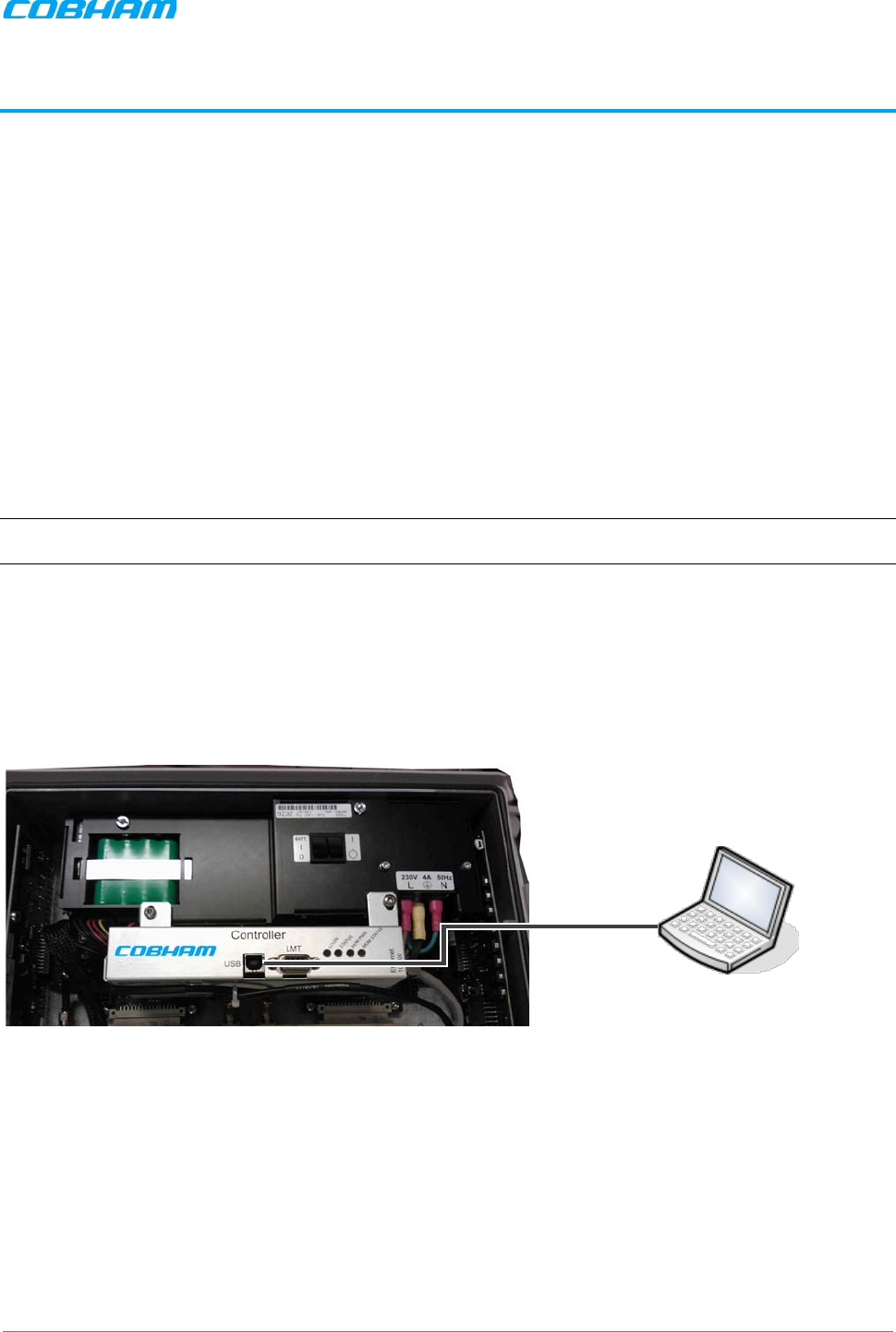
To open a local session:
1. Open the MBF-40 cover
• Connect to the USB port on the controller module. If the USB driver is not already installed on your
laptop, the system will search for the driver on the provided setup disk or on the internet (if a
network connection is available).
• Run a browser and login according to the following section.
Figure 3-1. MBF-40 Controller Module Connection
2. Open the web browser and enter following IP address in address bar: 192.168.152.1.
USB Cable
MBF-40 SMR900 PS REPEATER
PRODUCT DESCRIPTION AND USER’S MANUAL
Cobham Wireless – Coverage Date: 31-May-18 www.cobham.com/wireless
Doc. No. 00141UM Rev. 1.0 Page | 31
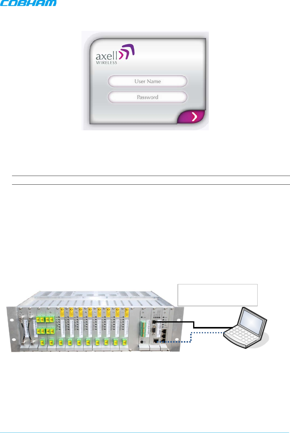
The login dialog appears.
Figure 3-2. Login Screen
3. Use the following username and password to login:
• Username: axell
• Password: AxellPasswd
Note: It is highly recommended to change the default password according to section 4.5.3.
The web GUI Main Window appears. This is the same window is also viewed via the OMU II.
3.1.2 Opening an Indirect Session (via the OMU II)
1. Open a local or remote session to the host OMU II:
• Remote session – open a Browser session in the same subnet as the host OMU II and enter the IP
of the host OMU II (see OMU user manual for detailed procedure). Enter the OMU II User Name
(e.g., axell) and Password (provided by your system administrator).
• Local session– connect to the OMU II control module's USB or Ethernet ports. Enter the OMU II User
Name (e.g., axell) and Password (provided by your system administrator).
• After accessing an OMU II session, commission the MBF-40 according to the following section.
Figure 3-3. Connection to OMU II
USB cable
Ethernet
bl
Connect to EITHER the USB
port OR Ethernet port
MBF-40 SMR900 PS REPEATER
PRODUCT DESCRIPTION AND USER’S MANUAL
Cobham Wireless – Coverage Date: 31-May-18 www.cobham.com/wireless
Doc. No. 00141UM Rev. 1.0 Page | 32
3.2 Navigating the Web Interface
MBF-40 is managed via web GUI, where the web GUI options differ according to the type of session.
This section describes the following web GUI options:
• Home screen — always available when a session is opened to the repeater.
• Menu buttons — available only when a direct session is opened to the repeater; when an OMU II session
is opened to the repeater, the menu button options are not available.
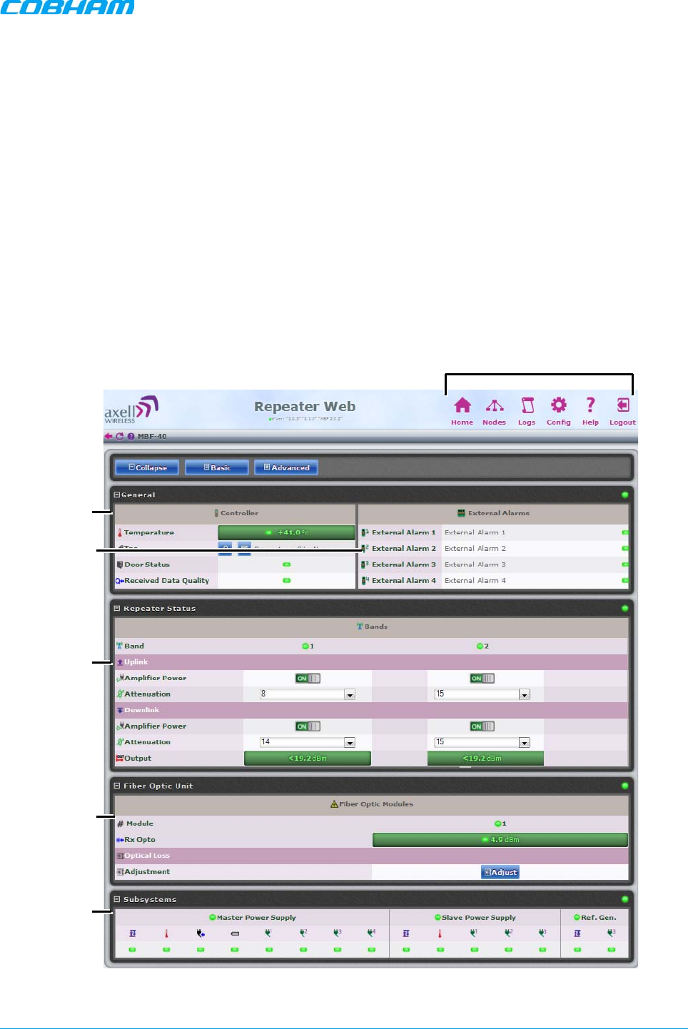
3.2.1 The Home Screen
The Home screen described below is always displayed when a session is opened to the repeater; however,
the menu options are only available with a direct session (not via OMU II).
The Home screen with the menu options is shown below. The various areas are briefly described in the
following page.
Figure 3-4. MBF-40 Home Screen
Menu Options — Available only with a Direct
Session to the Repeater (not via OMU II)
General
External
Alarms
UL and DL
Output Co
ntrol
Options
Fiber Optic
Options
Power
Monitoring
Options
MBF-40 SMR900 PS REPEATER
PRODUCT DESCRIPTION AND USER’S MANUAL
Cobham Wireless – Coverage Date: 31-May-18 www.cobham.com/wireless
Doc. No. 00141UM Rev. 1.0 Page | 33
The screen is divided into four basic areas:
• Controller – shows general information on the MBF-40 device such as identification and temperature
level.
• External Alarms – shows status of external alarms and the defined names.
• Repeater Status – RF connection status is divided into two sections:
• Band – shows general band status.
• Uplink/Downlink – gain, attenuation and connection status in the specific direction.
• Fiber Optic Unit – shows status on connection to remote OMU and allows for optical link adjustment.
• Sub-systems – overall status of all sub-systems such as power supplies, battery, communication etc.
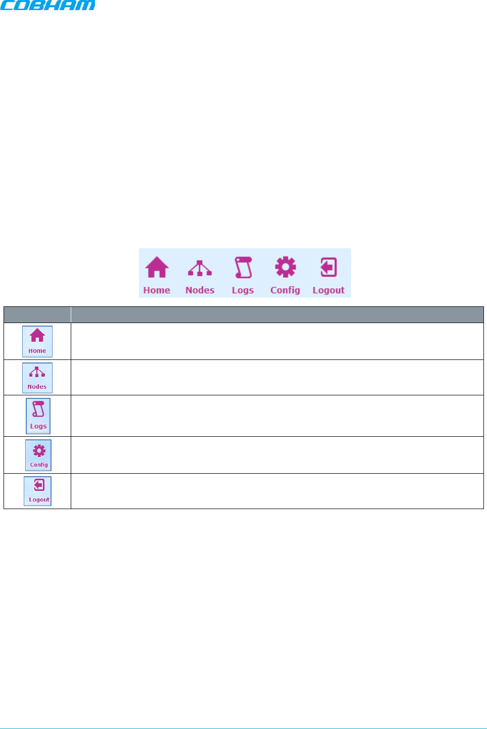
3.2.2 Menu Options Buttons
The menu options described below are only available via a direct session to the repeater.
Tab Description
Provides a general status and alarm information. Switching to
Advanced View
will toggle
a more detailed view of each band and module.
Lists the remote nodes – corresponding OMU and units connected the specific OMU.
List of recent operations. Section 5.2.
Provides a range of MBF-
40 configuration procedures such as communication, RF, Date
and Time, Password, etc. Section 4.3.
Logout of the system.
3.3 Commissioning the Repeater
After the repeater is connected to the OMU II, it is automatically identified by the OMU II via the Fiber
connection and the unit can then be commissioned from the OMU II. The commissioning process consists of
a few simple steps.
MBF-40 Setup and Commissioning consists of the following
1. Opening an OMU II session – for accessing the MBF-40 configuration window (via OMU II)
2. Recommended — configuring the MBF-40 Tag (site identification).
3. Performing optical loss adjustment on the connected MBF-40
4. Setting the required RF attenuation and gain levels on the remote MBF-40
5. Assigning the unit a recognizable name (according to its location)
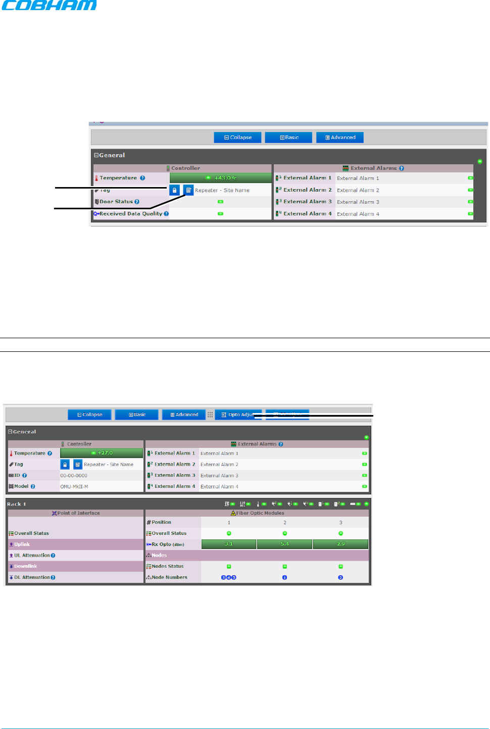
MBF-40 SMR900 PS REPEATER
PRODUCT DESCRIPTION AND USER’S MANUAL
Cobham Wireless – Coverage Date: 31-May-18 www.cobham.com/wireless
Doc. No. 00141UM Rev. 1.0 Page | 34
3.3.1 Defining Site Information – MBF-40 Identification
It is recommended to assign each MBF-40 a recognizable name that will identify the location, site name,
etc.
To set MBF-40 TAG
1. In the Home window, click the edit button next to Tag.
Figure 3-5. Set MBF-40 TAG Name
2. Enter the Name (up to 30 characters), click OK and click Apply.
3.3.2 MBF-40 Optical Loss Adjustment (OLA)
MBF-40 OLA is performed from the OMU II. For MBF-40 remotes, the maximum compensation is increased
to 26dB to support shorter Fiber optic distances.
NOTE: It is assumed that you have opened and OMU II session.
To perform MBF-40 OLA (via OMU II)
1. From the OMU II main window, click the Opto Adjust button.
Figure 3-6. OMU II Main window
Click “OptoAdjust”
Edit Tag
Lock Name
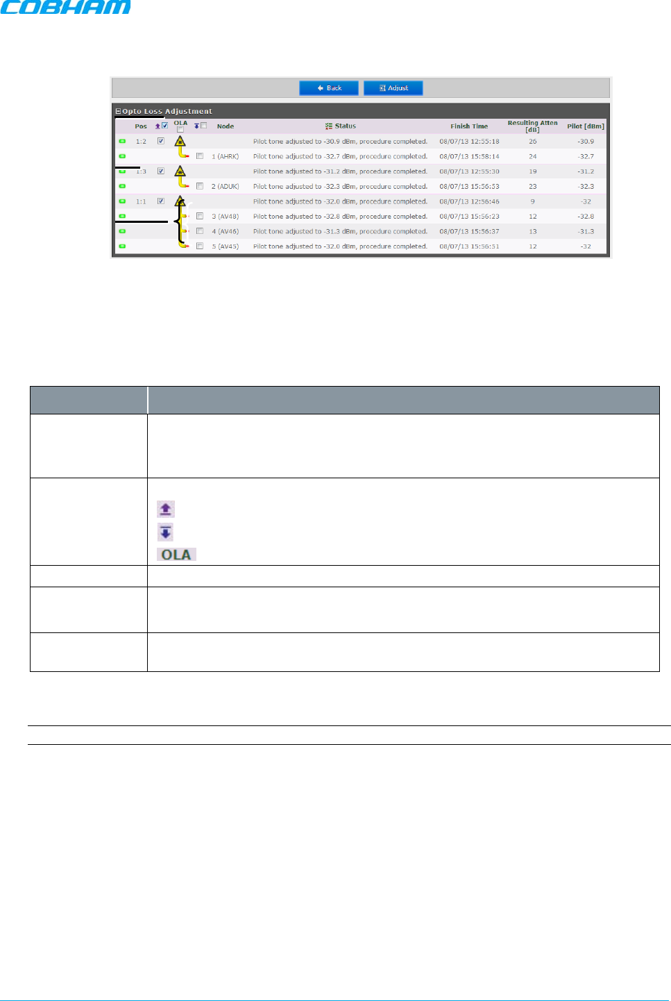
MBF-40 SMR900 PS REPEATER
PRODUCT DESCRIPTION AND USER’S MANUAL
Cobham Wireless – Coverage Date: 31-May-18 www.cobham.com/wireless
Doc. No. 00141UM Rev. 1.0 Page | 35
The OLA screen appears.
Figure 3-7. Configure and Initiate Optical Loss Adjustment
The screen lists the OLA options (and status) for each link. The links are listed according to the OMU II
slot to which the remote is connected.
A brief description of the OMU II OLA screen is given below.
Column Description
Pos Each rack corresponds to an OMU unit whereas each Slot corresponds to an
opto-module. Slots are numbered according to their position in the OMU chassis
(numbered left to right).
Select All Batch selection options:
- mark all remotes for UL opto-adjustment.
- mark all remotes for DL opto-adjustment.
- mark all remotes for DL and UL adjustment.
Node Node list number and identification (e.g. AHFK)
Status Displays an Error if process failed. If successful the pilot tone used and the
adjustment level will be displayed.
Resulting
Attenuation Compensation level used for the opto-module (in dB).
3. Mark the checkboxes corresponding to the MBF UL/DL node to be adjusted.
NOTE: The process may take several minutes depending on the size of the system and remote distance.
Rack#:Opto-
Module
Select Nodes for
UL/DL
Adjustment
F-
DAS Remotes
via Optic Splitter
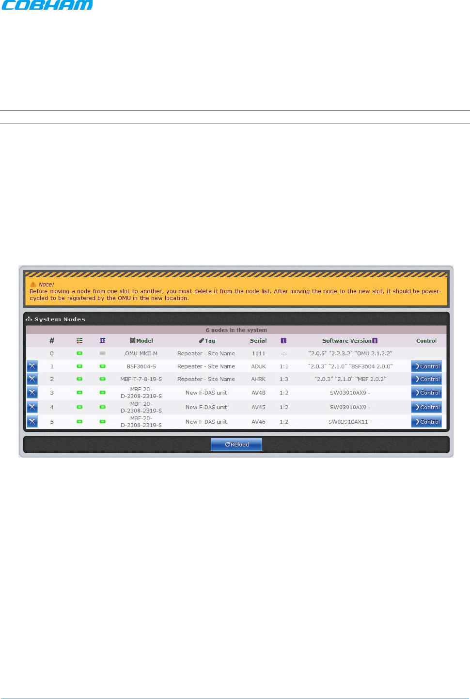
MBF-40 SMR900 PS REPEATER
PRODUCT DESCRIPTION AND USER’S MANUAL
Cobham Wireless – Coverage Date: 31-May-18 www.cobham.com/wireless
Doc. No. 00141UM Rev. 1.0 Page | 36
3.3.3 RF Balancing
The MBF-40 RF Balancing procedure can be performed manually (the automatic option specified in section
3.3.3.2 will be available in the future) via the OMU II web interface.
3.3.3.1 Manual RF Balancing
NOTE: If connected locally, enter the MBF-40 Home screen and skip to step 2.
The manual balancing procedure consists of the following steps:
• Verifying the DL RF output level is maximized by setting the required DL attenuation of the signal.
• Setting the UL attenuation according to the DL.
• In case of noise, adjusting the UL attenuation to reduce noise
To balance the MBF-40 UL and DL outputs
1. Access the MBF-40 Configuration window:
• Click on the Nodes button. The below pane appears
• Click Control next to the node to be balanced.
Figure 3-8. OMU Node Screen
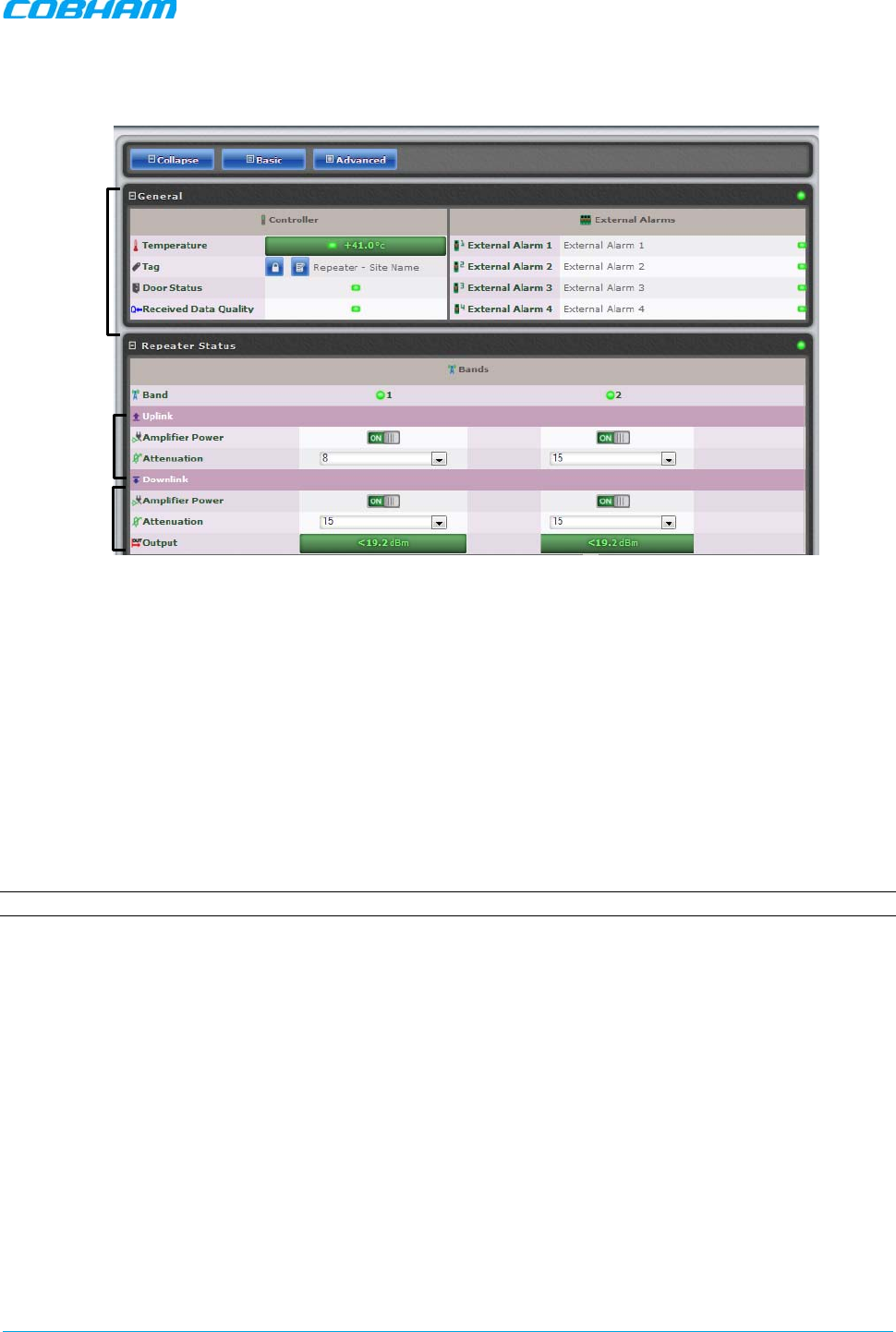
MBF-40 SMR900 PS REPEATER
PRODUCT DESCRIPTION AND USER’S MANUAL
Cobham Wireless – Coverage Date: 31-May-18 www.cobham.com/wireless
Doc. No. 00141UM Rev. 1.0 Page | 37
The repeater Home window appears.
Figure 3-9. Partial view of the MBF-40 Configuration window
2. In the Downlink:
• Verify the Amplifier for each band is ON.
• Set Attenuation to maximum value (15 dB).
• Lower the Attenuation level step by step until the desired Output power level is reached (Zero
attenuation = maximum gain).
• Verify the amplifier saturation is green.
3. In the Uplink:
• Verify the Amplifier for each band is ON.
• Set Attenuation equal to the value set in the DL (above).
• Verify the amplifier saturation is green.
NOTE: If noise is detected on the link, reduce only the uplink for optimal signal.
Band
Information
UL Setting
DL Setting
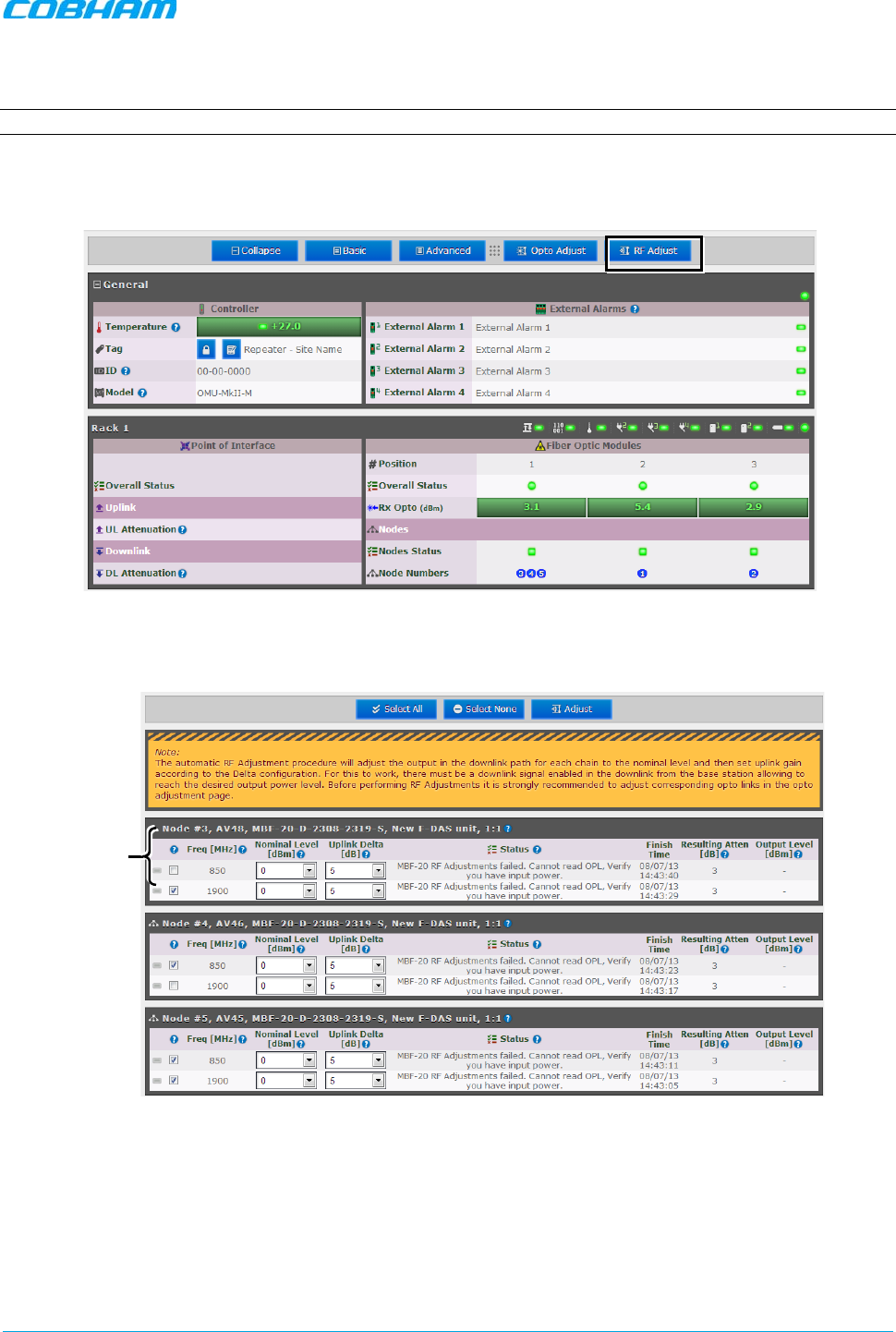
MBF-40 SMR900 PS REPEATER
PRODUCT DESCRIPTION AND USER’S MANUAL
Cobham Wireless – Coverage Date: 31-May-18 www.cobham.com/wireless
Doc. No. 00141UM Rev. 1.0 Page | 38
3.3.3.2 Automatic MBF-40 RF Balancing
NOTE: This feature will be available in future release.
To access the Automatic RF Adjustment pane
1. Access the OMU II Home window and click on RF Adjustment.
Figure 3-10. OMU II Main window
2. The following pane appears.
Figure 3-11. Adjust Window
3. Select the bands of each remote to be adjusted (e.g., 1900 MHz band on Node #3)
4. Adjust the following for each band:
• Nominal level (dBm)
• Uplink delta (dB)
5. Click Adjust. The procedure may take several minutes depending on the number of units selected.
Remote with
Selec
ted Bands
to Adjust

MBF-40 SMR900 PS REPEATER
PRODUCT DESCRIPTION AND USER’S MANUAL
Cobham Wireless – Coverage Date: 31-May-18 www.cobham.com/wireless
Doc. No. 00141UM Rev. 1.0 Page | 39
3.3.4 Integration into the AEM
NOTE: Integration into the AEM is only performed from the AEM side – no action is required from the MBF-40 side.
The AEM automatically connects to the repeater and downloads all the repeater information. The AEM then
configures the repeater with the IP address where alarms and reports should be sent to, and optionally with
a secondary IP address where the repeater can connect to in case connection to primary IP fails.
When heartbeat reports and alarms are sent from the repeater to the AEM also the latest information about
the status and RF-configuration is included. This means that the AEM operator always has information about
the current status in the AEM database (and does not need to call the repeater to find this out).
NOTE: Once the repeater is integrated to the AEM, all changes to the repeater should preferably be done from the
Element Manager in order to ensure that the database always contains correct information.
3.3.5 What Next?
The MBF-40 unit is now ready for operation. You may monitor the unit's general status via the OMU II Main
window and if the node is faulty (red LED), access the dedicated configuration screen in Basic or Advanced
view for more information.
NOTE: Consult the OMU II user manual for additional information on RF and optical adjustments.
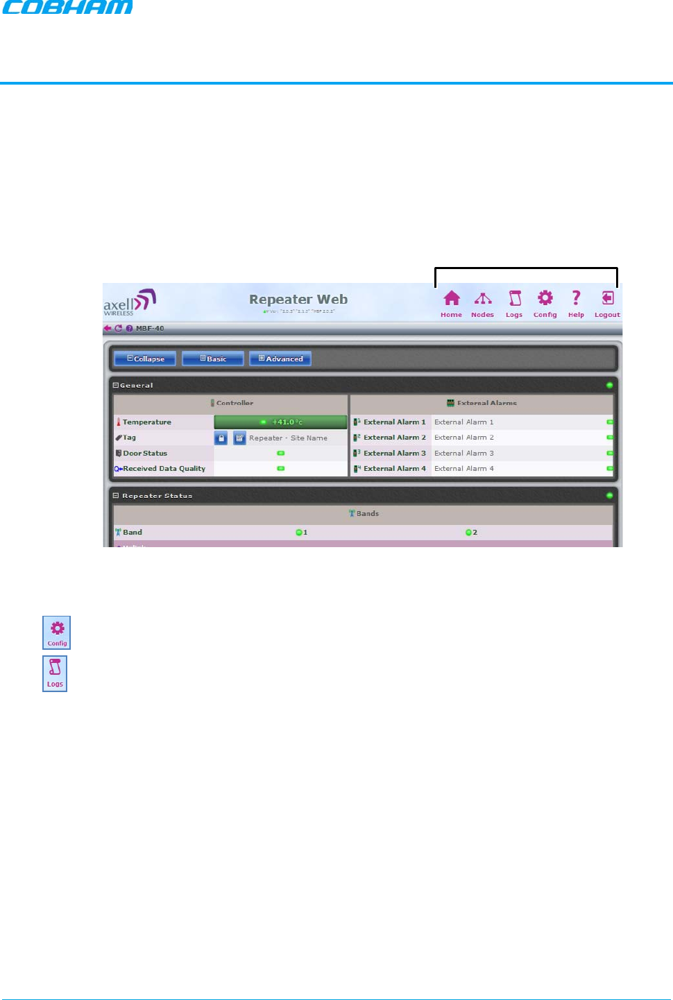
MBF-40 SMR900 PS REPEATER
PRODUCT DESCRIPTION AND USER’S MANUAL
Cobham Wireless – Coverage Date: 31-May-18 www.cobham.com/wireless
Doc. No. 00141UM Rev. 1.0 Page | 40
4 DIRECT ACCESS MENU OPTIONS
This chapter describes the menu options available ONLY when opening a direct session to the MBF-40.
4.1 Overview
The available menu options can be used to configure remote management options and for detailed fault
sourcing and troubleshooting.
Figure 4-1. MBF-40 Partial Home Screen with Menu Options
Two of the buttons are of special interest:
Provides a range of MBF-40 configuration procedures such as communication, RF, Date and
Time, Password, etc. Section 4.3.*
List of recent operations. Section 5.2.*
Menu Options — Available Only
(not via OMU II)
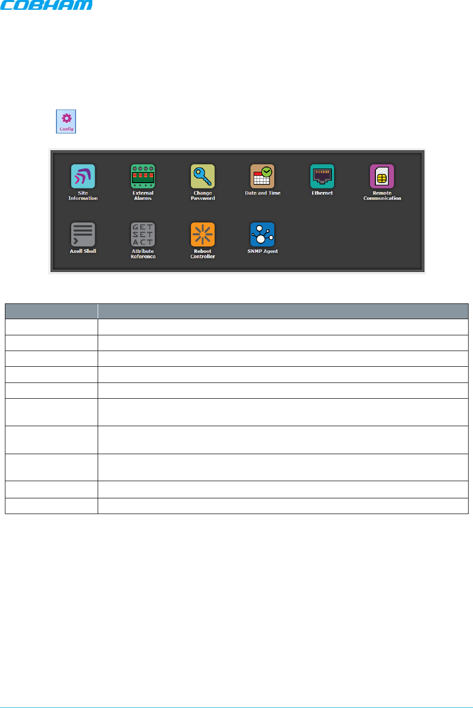
MBF-40 SMR900 PS REPEATER
PRODUCT DESCRIPTION AND USER’S MANUAL
Cobham Wireless – Coverage Date: 31-May-18 www.cobham.com/wireless
Doc. No. 00141UM Rev. 1.0 Page | 41
4.2 Configuration Screen Overview
The configuration screen provides access to a range of configuration and management options.
To access the configuration screen
Click on the menu option. The following screen appears.
Figure 4-2. Config Menu Options
Option Description
Site Information Configure and display MBF-40 identification information. See Section 4.3.1.
External Alarms Used to activate and assign names to external alarms. See Section 4.3.3.
Change password Used to update system login password for the logged-in user. See Section 4.5.3.
Date and Time Used to configure the time stamp for dating MBF-40 events. See Section 4.3.2.
Ethernet Used to define the IP Address for remote access via Ethernet. See section 0.
Remote
Communication
Used to configure remote communication parameters and AEM integration. See
section 4.4.
Axell Shell Command line used to communicate with the remote units. List of commands is
found under Help. See Section 4.7.
Attribute
Reference CLI commands and attributes directory. See Section 4.8.
Reboot controller Soft restarts the MBF-40 device. See Section 4.6.
SNMP Agent SNMP Agent configuration. See Section 4.4.2.
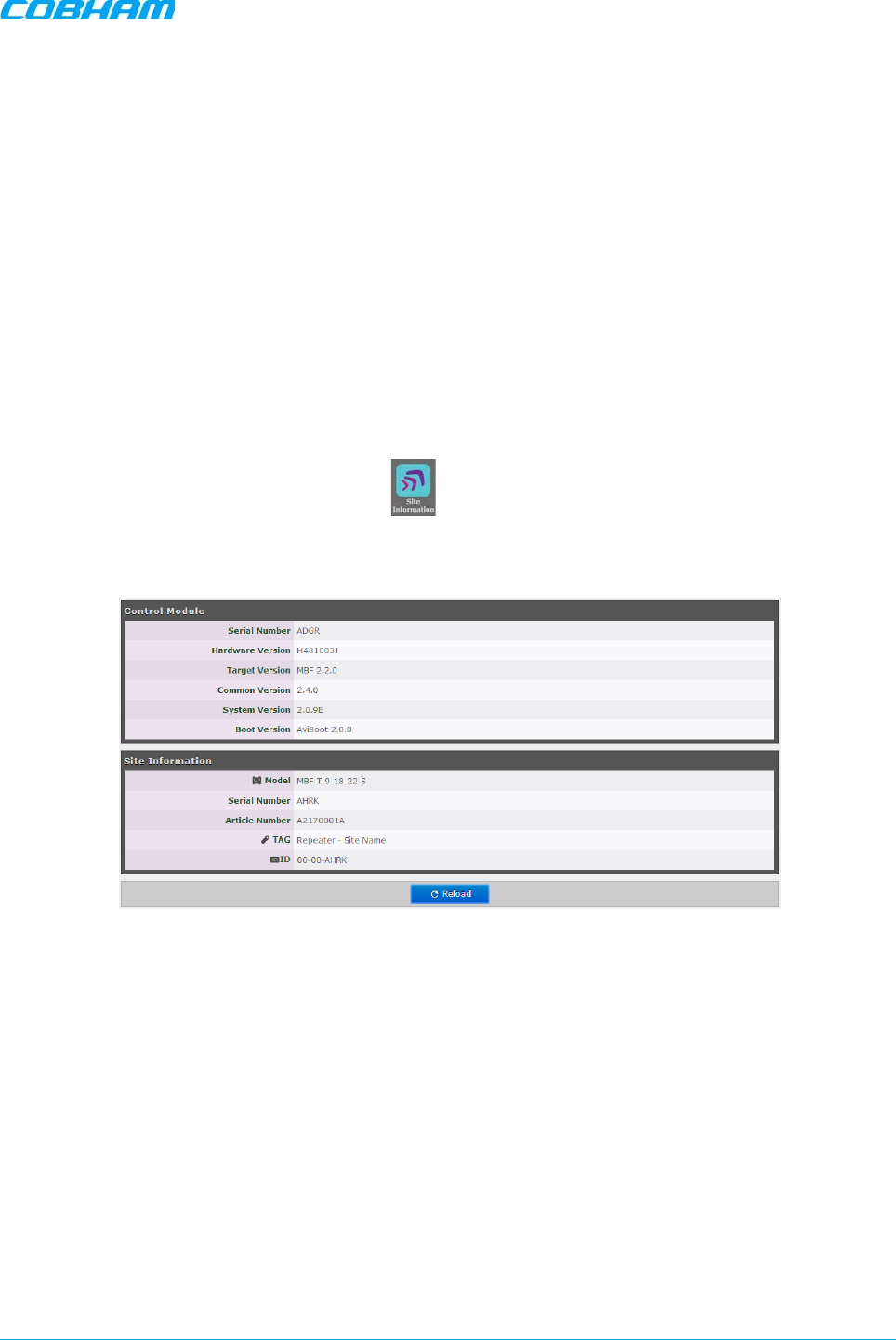
MBF-40 SMR900 PS REPEATER
PRODUCT DESCRIPTION AND USER’S MANUAL
Cobham Wireless – Coverage Date: 31-May-18 www.cobham.com/wireless
Doc. No. 00141UM Rev. 1.0 Page | 42
4.3 General Parameters
This section describes the following options:
• Viewing site information and repeater information (repeater ID, SW and HW versions, etc.)
• Date and time
• Configuring external alarms
• Setting Ethernet IP address
4.3.1 Viewing MBF-40 Site Identification and General
Information
The Site Information button provides access to MBF-40 hardware and software version information.
To view MBF-40 Site Information
Click the Config menu button and click on the icon. Two areas are displayed:
• Control Module – provides hardware and software version information.
• Site Information – provides MBF-40 identification information.
Figure 4-3. MBF-40 Site Information
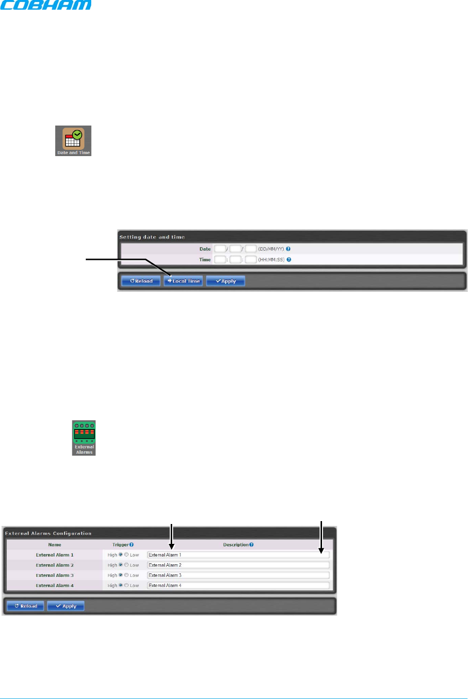
MBF-40 SMR900 PS REPEATER
PRODUCT DESCRIPTION AND USER’S MANUAL
Cobham Wireless – Coverage Date: 31-May-18 www.cobham.com/wireless
Doc. No. 00141UM Rev. 1.0 Page | 43
4.3.2 Date & Time
The repeater date and time are automatically set from the OMU II. However, the option for direct settings is
available as well.
To set the Date & Time:
1. Click the Config button.
2. Click on icon.
3. Do one of the following:
• Either, enter the correct date and time according to the displayed formats.
• Or, click on Local Time to set the time according to the PC running the Web-GUI.
4. Click Apply.
Figure 4-4. Configure Date and Time
4.3.3 Configure External Alarms
It is required to configure any connected external alarms according to the trigger (high or low) and it is
recommended to assign the alarms recognizable names (such as Door Open, High Temperature, etc.)
To configure the external alarms
1. In the Main menu, click the Config button.
2. Click on the icon.
3. For each alarm:
• Set the Trigger as High or Low as required.
• Assign the alarm a recognizable description
4. Click Apply.
Figure 4-5. Configure External Alarms
Set to local time
Enter Alarm
Description
Set High/Low
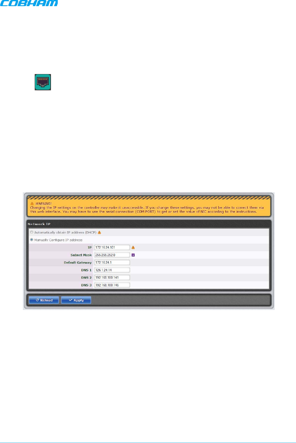
MBF-40 SMR900 PS REPEATER
PRODUCT DESCRIPTION AND USER’S MANUAL
Cobham Wireless – Coverage Date: 31-May-18 www.cobham.com/wireless
Doc. No. 00141UM Rev. 1.0 Page | 44
4.3.4 IP Address
This procedure describes how to set up the IP address either manually or configure for acquisition via DHCP
(usually configured for local management options).
To configure the IP address
1. In the Main menu, click the Config button.
2. Click on icon.
3. For manual IP address configuration:
• Select Manually Configure IP Address.
• Set the IP, subnet mask, default gateway and DNS addresses.
• Click “Apply”.
4. For DHCP IP address configuration:
• Select “Automatically Obtain IP Address” (DHCP).
• No other settings are required.
• Click “Apply”.
The Manual configuration settings are illustrated below.
Figure 4-6. Configure Local Network Parameters
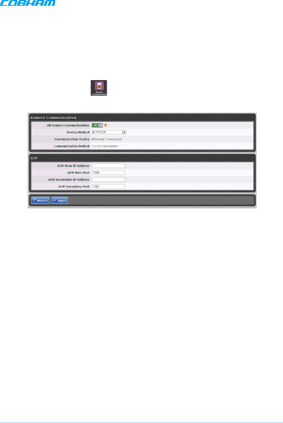
MBF-40 SMR900 PS REPEATER
PRODUCT DESCRIPTION AND USER’S MANUAL
Cobham Wireless – Coverage Date: 31-May-18 www.cobham.com/wireless
Doc. No. 00141UM Rev. 1.0 Page | 45
4.4 Remote Communication Setup
This section describes the Ethernet and SNMP setup.
4.4.1 TCP/IP and Ethernet
1. Click on the Config menu button.
2. From Device: Method select (Ethernet: TCP/IP).
3. Click Apply.
Figure 4-7. Remote ETH Configuration
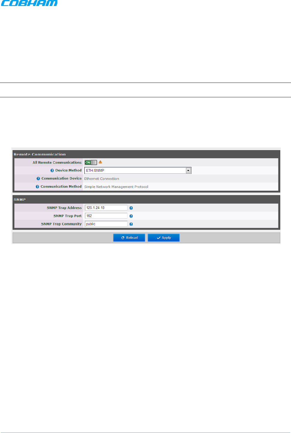
MBF-40 SMR900 PS REPEATER
PRODUCT DESCRIPTION AND USER’S MANUAL
Cobham Wireless – Coverage Date: 31-May-18 www.cobham.com/wireless
Doc. No. 00141UM Rev. 1.0 Page | 46
4.4.2 SNMP Support
The MBF-40 includes SNMP support, including an SNMP Agent and SNMP traps (alarms). All SNMP queries
and traps are supported either via the OMU II or a direct connection to the unit.
4.4.2.1 SNMP Traps Parameters
The MBF-40 sends SNMP traps to user defined destination addresses.
NOTE: One destination address can currently be defined via the Web. Seven more destination addresses can be defined
via the Shell application.
To configure the SNMP traps destination address
1. Click on the Configure button (top right corner).
2. Select “Remote Communication”.
3. In the Device: Method field, select “ETH:SNMP”.
Figure 4-8. Remoter Communication and SNMP Display Areas
4. Define the SNMP trap destination IP address (additional addresses can be defined via the Axell shell.).
5. Enter the (destination address device) Trap Port and its Community parameters.
6. Click “Apply”.
4.4.2.2 SNMP Agent - Activating and Configuring
The SNMP agent provides inventory management for hosted repeaters (on which the SNMP agent is
enabled) and a table of active alarms in the controller or Fiber system for remote querying.
The SNMP Agent is responsible for responding to queries and carries out requests. The SNMP Agent also
provides the proprietary Axell MIB (AXELL-AM-MIB), accessible via any SNMP manager (e.g., HP OpenView).
All SNMP queries to the remote are implemented via an OMU session.
To allow SNMP agent queries
• To allow SNMP queries of the OMU II – the SNMP agent must be enabled on the OMU II.
• To allow SNMP queries of the remote devices via OMU II – the SNMP agent must be enabled on the
OMU II and on the remote devices.
• Remote units configured with an IP address and connected to the communication infrastructure, can be
queried directly.
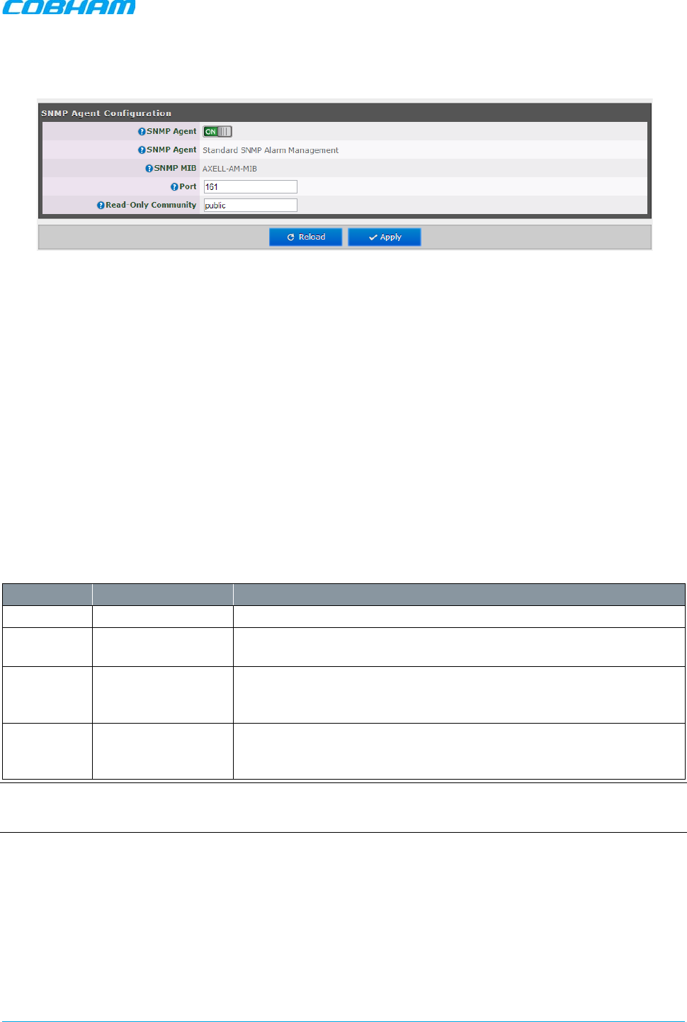
MBF-40 SMR900 PS REPEATER
PRODUCT DESCRIPTION AND USER’S MANUAL
Cobham Wireless – Coverage Date: 31-May-18 www.cobham.com/wireless
Doc. No. 00141UM Rev. 1.0 Page | 47
To activate the MBF-40 SNMP Agent
1. Click on the Config button (top right corner) and select SNMP Agent Config. The following pane appears:
Figure 4-9. SNMP Agent Configuration Display Area
2. Set the SNMP Agent toggle to ON.
3. Set the port and the Read-Only community.
4. Click Apply.
4.5 User Accounts
The MBF-40 comes pre-configured with default usernames and passwords in the various administration
levels.
At the moment, updating user accounts is available only via command line interface (CLI) or Axell Shell. See
the Common Commands and Attributes v2.4.0 document for detailed commands and syntax or click on the
Help button at the top right of the Web-GUI screen.
4.5.1 Default User Accounts
User Name Default Password Details
Axell AxellPasswd Default user name.
omcuname iwnkhoob Element Manager (AEM) user account. This account will not generate
VLI, LGO or CLR alarms.
sysadmin AxellAdmin4050
This is the system administration password which is used for
firmware upgrades and user administration. Escalation to this level is
achieved by issuing command SYSADMIN from the user prompt.
useradmin UseradminPwd23 This account contains user administration privileges. Escalation to
this level is achieved by issuing command USERADMIN from the user
prompt.
NOTE: It is strongly recommended to change the default user names and passwords immediately at commissioning. This
is done by using the command ACT PASSWORD. Please refer to the User Administration section in Common
Commands and Attributes document for detailed syntax.
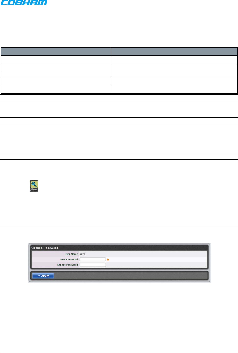
MBF-40 SMR900 PS REPEATER
PRODUCT DESCRIPTION AND USER’S MANUAL
Cobham Wireless – Coverage Date: 31-May-18 www.cobham.com/wireless
Doc. No. 00141UM Rev. 1.0 Page | 48
4.5.2 User Access Levels
In this generation of the system, standard users can be promoted to login via the web Interface, inheriting
the read-write or read-only access to this interface.
There are five different access levels:
Access Level Default User Levels
Read-Only axell, omcuname, useradmin, sysadmin
Read-Write axell, omcuname, useradmin, sysadmin
Web axell
User Administrator omcuname, useradmin, sysadmin
System Administrator omcuname, sysadmin
Note: New users added to the system have read-only access.
Users may be promoted to read-write and/or web access using the ACT USERPROMOTE command. See
Common Commands and Attributes document for details on promoting users.
Note: Users omcuname, sysadmin and useradmin cannot be promoted to Web Access due to security reasons.
4.5.3 Change Password
To prevent unauthorized access, it is highly recommended to change the default password of the user.
NOTE: Note that you can only change the password for the User Name with which the session was accessed.
To change the Password
1. In the Main menu, click the Config button.
2. Click the icon.
3. For the current user name (e.g., axell):
• Enter the new password.
• Repeat the entry.
4. Click “Apply”.
NOTE: The password is not encrypted during transmission. If the connection to the repeater is not safe, do not use this
screen. Use the CLI commands using an encrypted connection, if possible (i.e. SSH).
Figure 4-10. Change Password Dialog
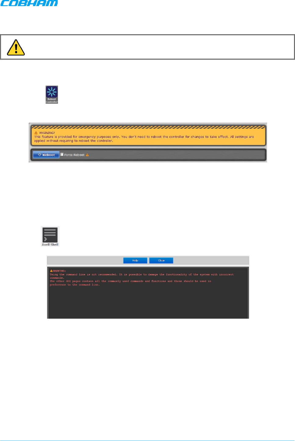
MBF-40 SMR900 PS REPEATER
PRODUCT DESCRIPTION AND USER’S MANUAL
Cobham Wireless – Coverage Date: 31-May-18 www.cobham.com/wireless
Doc. No. 00141UM Rev. 1.0 Page | 49
4.6 Reboot
CAUTION! USE THE REBOOT FUNCTION ONLY IN CASE OF EMERGENCY!
To reboot the Control Module:
1. Click the Config tab.
2. Click on the icon.
3. Approve the Reboot sequence.
Figure 4-11. Reboot Option Dialog
4.7 Axell Shell (Command Line Interface)
To access the Axell Shell:
1. Click on the Config button.
2. Select the option.
Figure 4-12. Axell Shell Window
The Axell Shell button invokes the CLI pane. It is used to run some of the commands that are currently not
provided by the Web GUI (user privileges and administration) and/or for advanced troubleshooting and
configurations procedures.
All configuration and management procedures can be implemented using this interface. Please refer to the
Attribute Reference
section (by clicking the Cofing button on the top right and selecting Attribute Reference
– see Section 4.8) for detailed syntax and available commands. You may also consider viewing the “MBF-40
Commands and Attributes”
document.
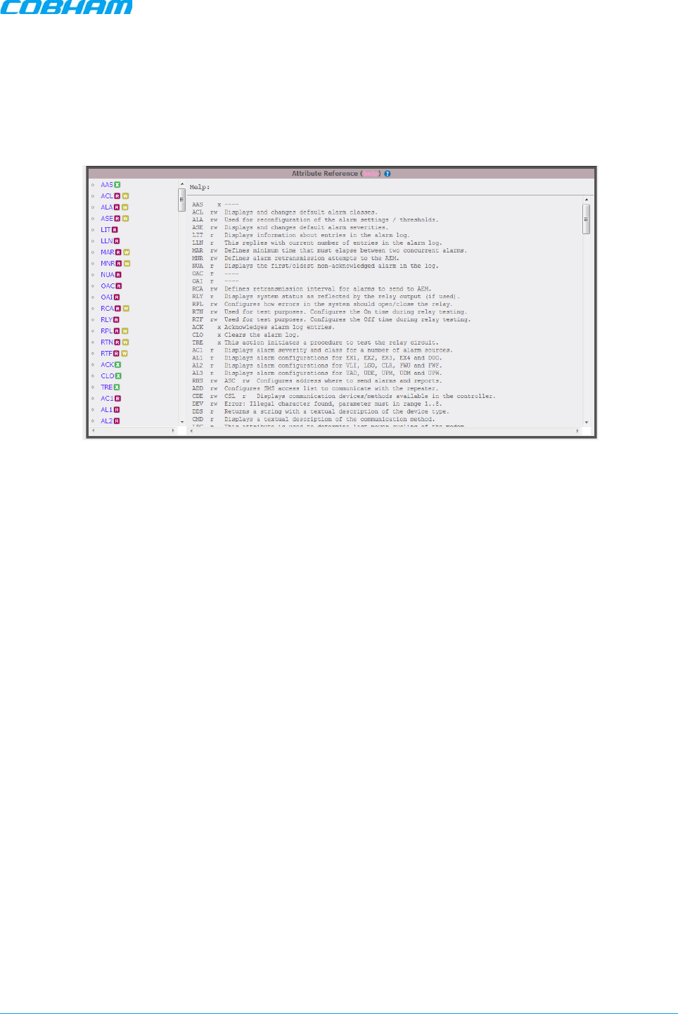
MBF-40 SMR900 PS REPEATER
PRODUCT DESCRIPTION AND USER’S MANUAL
Cobham Wireless – Coverage Date: 31-May-18 www.cobham.com/wireless
Doc. No. 00141UM Rev. 1.0 Page | 50
4.8 Attribute Reference
To access the Attribute Reference
1. Click on the Config button.
2. Select the “Attribute Reference” option.
Figure 4-13. Attribute Reference Display
The Attribute Reference lists all available CLI commands and includes details and examples on how to use
the commands. Additional information may be found in the
MBF-40 Commands and Attributes
document.

MBF-40 SMR900 PS REPEATER
PRODUCT DESCRIPTION AND USER’S MANUAL
Cobham Wireless – Coverage Date: 31-May-18 www.cobham.com/wireless
Doc. No. 00141UM Rev. 1.0 Page | 51
5 MONITORING AND FAULT SOURCING
MBF-40 provides the following monitoring and fault sourcing options:
• Web GUI Home screen Advanced mode — shows general status of system and components
• Web GUI Logs screen — provides logs of faults and operations
• Module LEDs — can be seen locally when opening the Repeater
This chapter describes these fault sourcing tools.
Note the following
• The input/output RF level power level monitoring windows are for indication only and should not be
considered a replacement for laboratory test equipment accuracy of measurement of actual signal levels.
The error of measurement will be high at low input levels.
• The normal operating range of signal measurement is as follows:
• Downlink Output range +20 dBm to +43 dBm
• Uplink Output range -10 dBm to +5d Bm
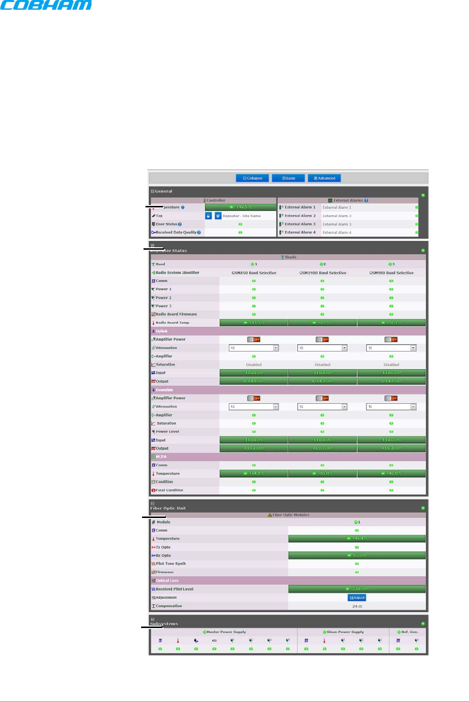
MBF-40 SMR900 PS REPEATER
PRODUCT DESCRIPTION AND USER’S MANUAL
Cobham Wireless – Coverage Date: 31-May-18 www.cobham.com/wireless
Doc. No. 00141UM Rev. 1.0 Page | 52
5.1 Monitoring Via the MBF-40 Home Screen
In addition to RF settings and readings, the MBF-40 Home screen provides detailed information on the
operation status of internal modules. This information can be used to aid in remotely troubleshooting the
Remote.
To access the MBF-40 Main Monitoring and Configuration window
1. Access the OMU II main windows, click the Nodes button, choose the remote related node and click the
adjacent Control button. The MBF-40 Home window appears in Basic View. To view more details, click
Advanced.
Figure 5-1. MBF-40 Main Screen Advanced
General
(Same as Basic View)
Detailed Repeater
Status View
Detailed Fiber Optic
Status
Power Measurements
Status
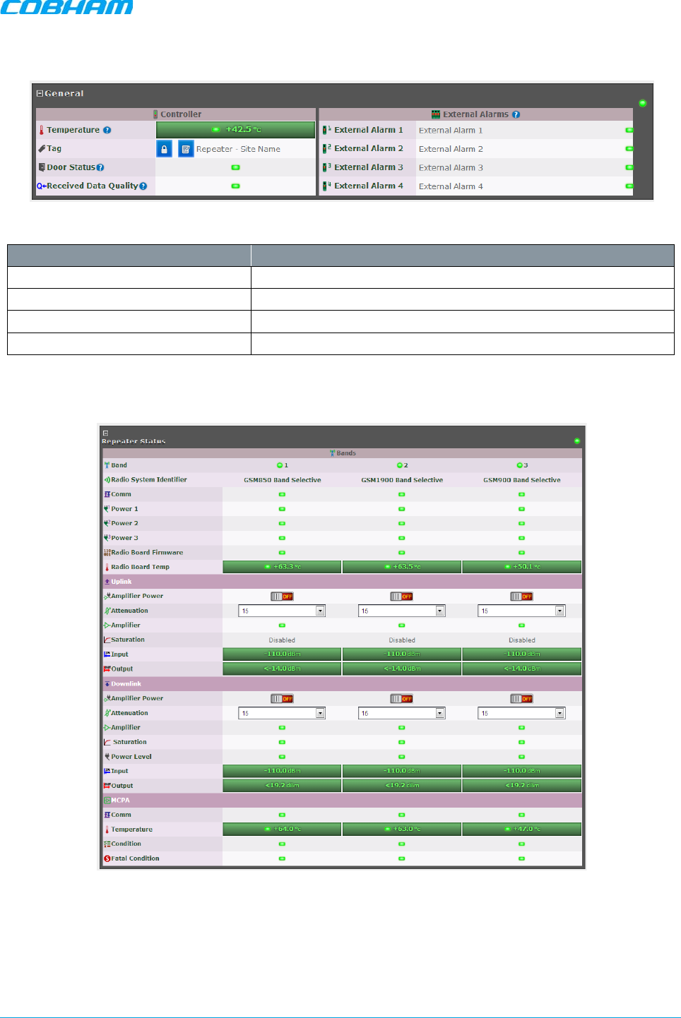
MBF-40 SMR900 PS REPEATER
PRODUCT DESCRIPTION AND USER’S MANUAL
Cobham Wireless – Coverage Date: 31-May-18 www.cobham.com/wireless
Doc. No. 00141UM Rev. 1.0 Page | 53
5.1.1 General Page Area
Figure 5-2. MBF-40 General
Indicator Description
Temperature Current ambient temperature
Tag Name of Repeater, user customizable
Door Status Green if closed
Received Data Quality Check data for consistencies
5.1.2 Detailed view of the MBF-40
Figure 5-3. MBF-40 Repeater Status

MBF-40 SMR900 PS REPEATER
PRODUCT DESCRIPTION AND USER’S MANUAL
Cobham Wireless – Coverage Date: 31-May-18 www.cobham.com/wireless
Doc. No. 00141UM Rev. 1.0 Page | 54
Indicator Description
Band Overall band status.
Radio System Identifier Band(s) and technologies in use
Comm DL/UL status
Power Power indication
Radio Board Firmware Firmware related error
Radio Board Temp Radio board temperature indicator
Amplifier Power Turn amp. on/off.
Attenuation Use to define DL/UL RF attenuation level per band
Amplifier Amplifier status
Saturation Saturation level status
Power Level Power supply status
Input/Output Input/output power levels
Comm Communication status
Temperature Temperature level and status indicator
Condition Signal conditioning status
Fatal Condition Critical condition indicator (RED = fault)
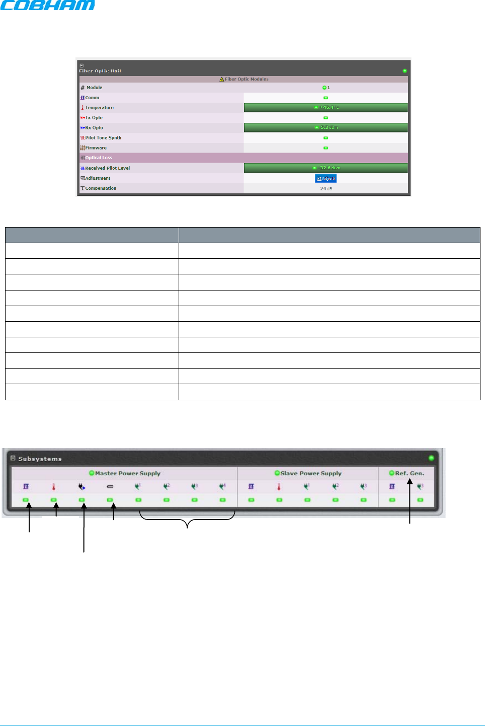
MBF-40 SMR900 PS REPEATER
PRODUCT DESCRIPTION AND USER’S MANUAL
Cobham Wireless – Coverage Date: 31-May-18 www.cobham.com/wireless
Doc. No. 00141UM Rev. 1.0 Page | 55
5.1.3 Detailed view of Fiber Optic Unit
Figure 5-4. MBF-40 F/O Status
Indicator Description
#Module Overall optic module status
Comm Optic connection status
Temperature Temperature level and status indicator
Tx Opto DL optic signal status
Rx Opto UL optic signal strength and status
Pilot Tone Synth Pilot tone synthesizer status
Firmware Firmware related error
Received Pilot Level Pilot tone level received in optic module
Adjustment Perform UL OLA (on repeater side)
Compensation Compensation performed on the optic link
5.1.4 Subsystems
Figure 5-5. Subsystems Alarms Display
Comm.
Temp
Pwr.
Input
Batt.
Status
Pwr.
Modules
Status
Reference
Generator
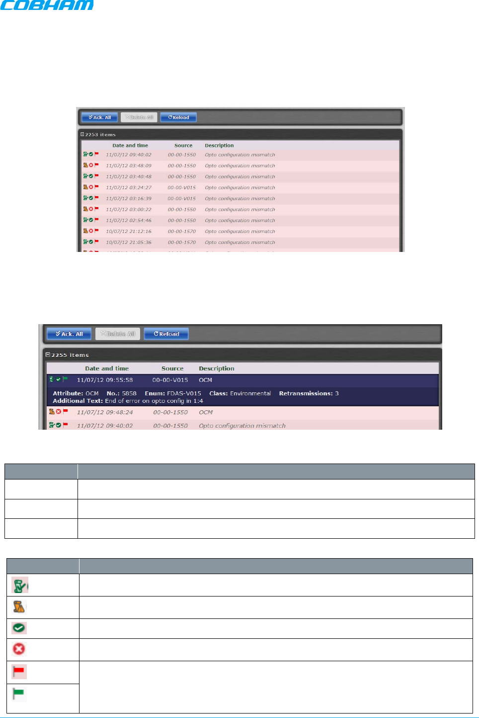
MBF-40 SMR900 PS REPEATER
PRODUCT DESCRIPTION AND USER’S MANUAL
Cobham Wireless – Coverage Date: 31-May-18 www.cobham.com/wireless
Doc. No. 00141UM Rev. 1.0 Page | 56
5.2 Logs Screen
The Alarms Log displays the last 100 alarms and/or user actions on the remote system in a chronological
order. By hovering with the mouse over each alarm, full alarm details are available, including alarm
descriptions, severities, alarm classes and time of event.
Figure 5-6. Logs
To receive a summary containing all information on a reported incident in the Log list, simply hover with the
mouse over the specified Log and view all details contained in the Log (see below).
Figure 5-7. Logs —Summary
Column Description
Date & Time Time of occurrence
Source ID of reporting source
Description Additional alarm information (e.g. Open Door)
Icon Description
Alarm attended to and cleared.
System alarm – displayed when system functionality may be compromised.
Alarm status: OK
Alarm status: Error
Acknowledge alarm – Green = Acknowledged.
Click to change acknowledgement.
Use the Ack All button to acknowledge all alarm logs.

MBF-40 SMR900 PS REPEATER
PRODUCT DESCRIPTION AND USER’S MANUAL
Cobham Wireless – Coverage Date: 31-May-18 www.cobham.com/wireless
Doc. No. 00141UM Rev. 1.0 Page | 57
5.3 Module LEDs
This section describes the LEDs of the internal modules. The modules are accessed if the remote is opened.
An example of the MBF-40 model is shown in Figure 5-8.
Figure 5-8. Internal View (Door Open)
Control module
LEDs
Optic converter module LEDs
Power Supply
LEDs
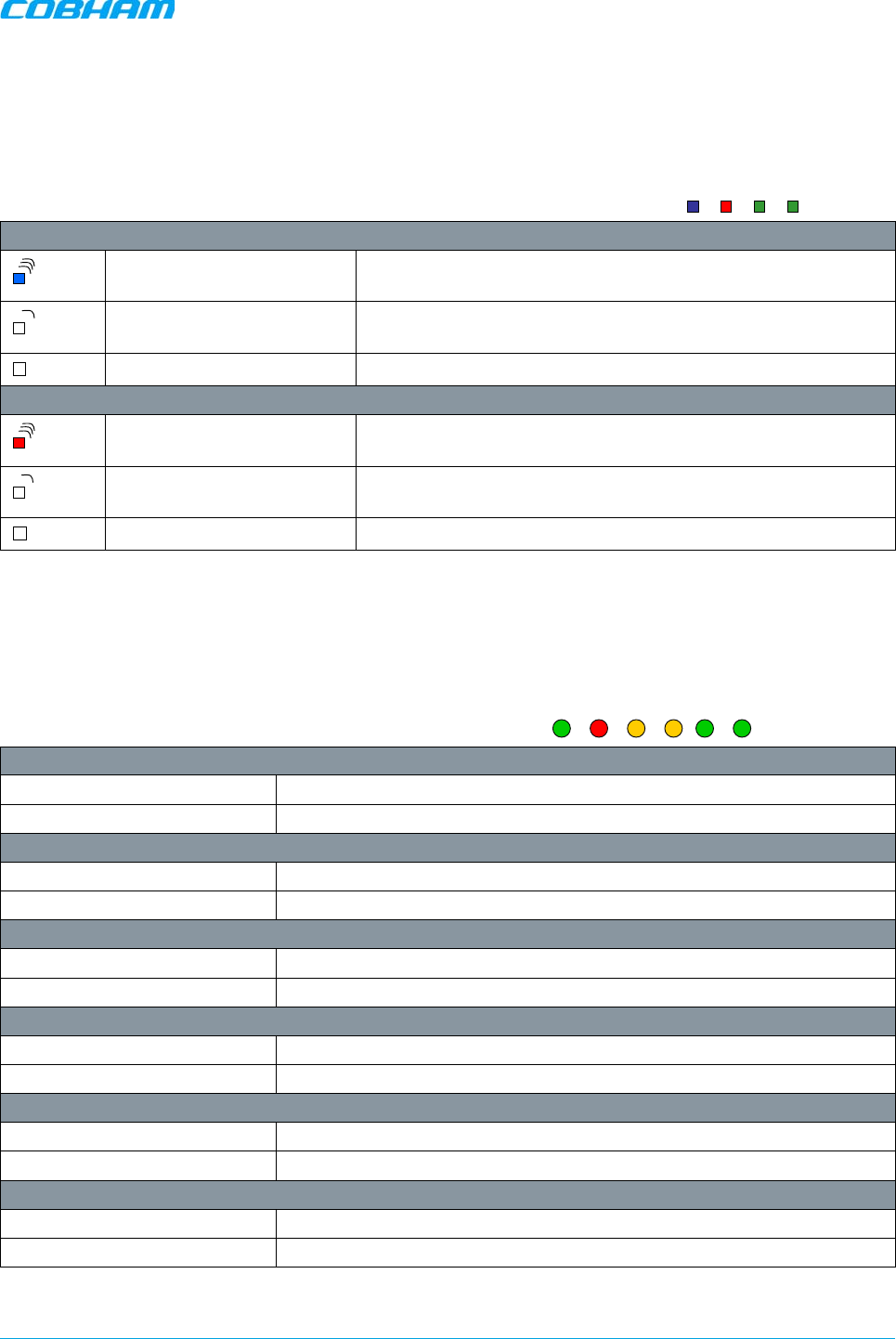
MBF-40 SMR900 PS REPEATER
PRODUCT DESCRIPTION AND USER’S MANUAL
Cobham Wireless – Coverage Date: 31-May-18 www.cobham.com/wireless
Doc. No. 00141UM Rev. 1.0 Page | 58
5.3.1 Control Module LEDs
The Control Module has four LEDs which give information regarding the status
of the MBF-40.
The two LEDs “Modem Power” and “Modem Status” do not fill any function and
can be disregarded.
Blue LED - Login
Quick flash Control Module switched on, someone logged in locally and/or
remotely
Off (except for a quick flash
every 10th second) Control Module switched on, no one logged in
Off (permanent) Control Module switched OFF
Red LED - Status
Quick flash Control Module switched o
n, one or more errors/alarms
detected
Off (except for a quick flash
every 10th second) Control Module switched on, status OK
Off (permanent) Control Module switched off
5.3.2 F/O Converter LEDs
There are 6 LEDs on the module to indicate the status.
LED 1, Power, Green
On Unit is powered on
Off Unit has no power
LED 2, Error, Red
On Error detected
Off No error
LED 3, UL Data, Yellow
On Communication is ongoing in the uplink direction
Off No communication
LED 4, DL Data, Yellow
On Communication is ongoing in the downlink direction
Off No communication
LED 5, Opto Rx, Green
On Received RF signal on Fiber channel is above threshold
Off Input level below threshold
LED 6, Opto Tx, Green
On Transmitted RF signal on Fiber channel is above threshold
Off Output level below threshold
Modem Status
Modem Power
Status
Login
PWR
ERR
UL Data
DL Data
Opto Rx
Opto Tx
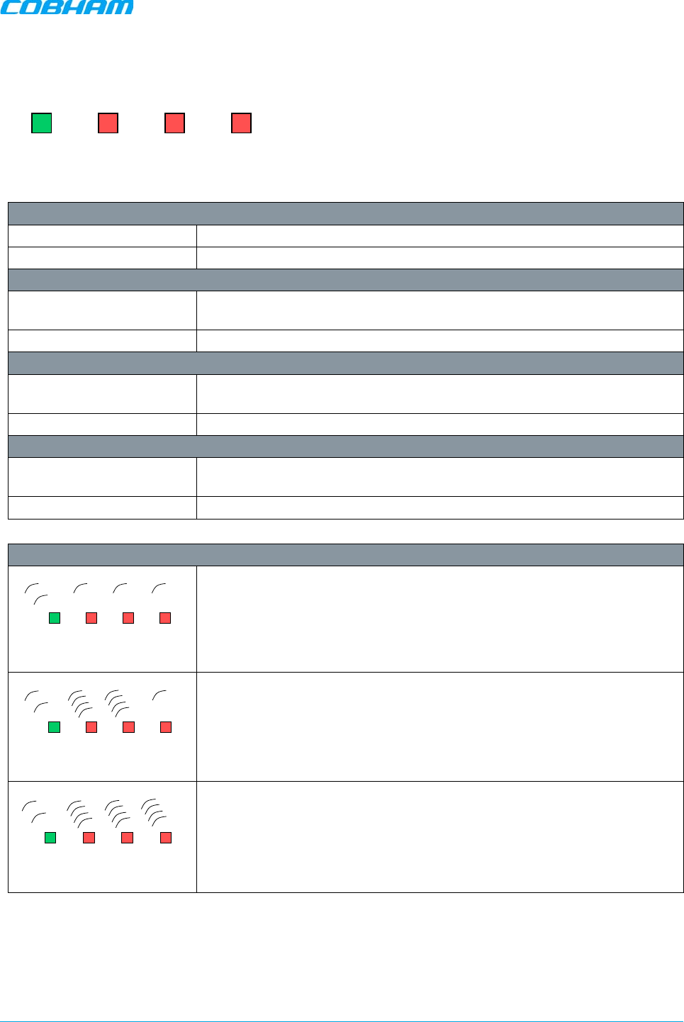
MBF-40 SMR900 PS REPEATER
PRODUCT DESCRIPTION AND USER’S MANUAL
Cobham Wireless – Coverage Date: 31-May-18 www.cobham.com/wireless
Doc. No. 00141UM Rev. 1.0 Page | 59
5.3.3 Power Supply LEDs
This section provides a detailed description of the LEDs and fault examples.
LED 1, Input Power, Green
Slow flash Power supply unit operating on AC or DC
OFF Power supply unit not operating
LED 2, +6V, Red
Slow flash (every 10
seconds) +6V power supply operating
Quick flash +6V power supply not operating or operating with malfunction
LED 3, +15V, Red
Slow flash (every 10
seconds) +15V power supply operating
Quick flash +15V power supply not operating or operating with malfunction
LED 4, +28V, Red
Slow flash (every 10
seconds) +28V power supply operating
Quick flash +28V power supply not operating or operating with malfunction
Examples
LED 1 is flashing slowly, LED 2 – 4 are flashing slowly (once every 10
seconds)
=> power supply unit is operating without problem
LED 1 is flashing slowly, one or two of the red LEDs are flashing quickly
=> Input power is operating but there is a problem with some of the other
voltages
LED 1 is flashing slowly, all of the red LEDs are flashing quickly
=> Input power is out and unit is operating on backup battery
Input
Power +6V +15V +28V
Input
Power +6V +15V +28V
Input
Power +6V +15V +28V
Input
Power +6V +15V +28V
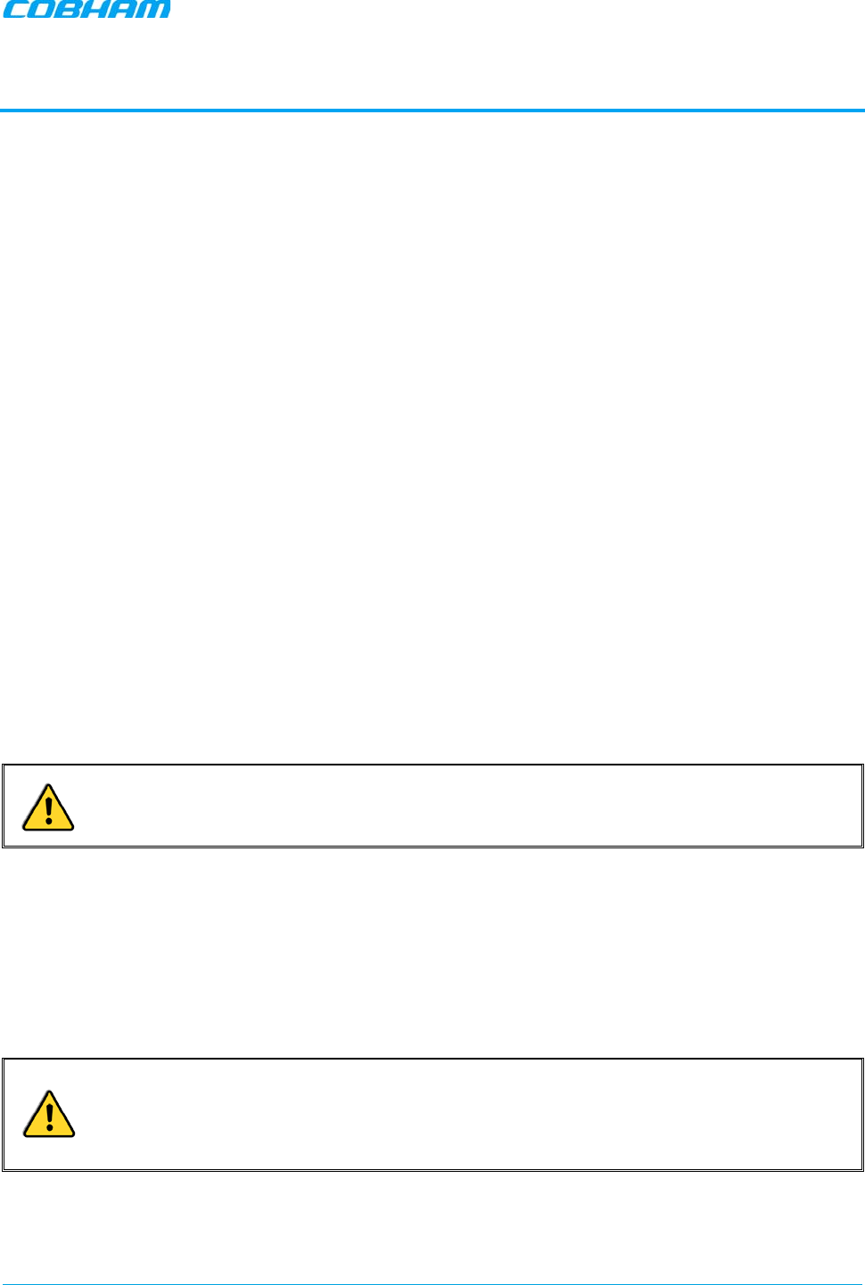
MBF-40 SMR900 PS REPEATER
PRODUCT DESCRIPTION AND USER’S MANUAL
Cobham Wireless – Coverage Date: 31-May-18 www.cobham.com/wireless
Doc. No. 00141UM Rev. 1.0 Page | 60
6 MAINTENANCE
6.1 Cautions and General Statements
• The system normally operates without any operator intervention or maintenance. If in the unlikely event
of any unit failure, the faulty repeater should be replaced. A failed unit can be removed and replaced
with a spare while the rest of the system (other repeaters) is still operating. However, the power supply
of the failed repeater should be isolated from the power before anything is replaced.
• In the event of a malfunction in the system, the status of the antenna systems as well as the continuity
of the cabling should be checked before replacing any modules within the repeater.
• The input / output RF level power level monitoring windows are for indication only and should not be
considered a replacement for laboratory test equipment accuracy of measurement of actual signal levels.
The error of measurement will be high at low input levels.
• The normal operating range of signal measurement is as follows:
• Downlink Output range +20 dBm to +43 dBm
• Uplink Output range -10 dBm to +5 dBm
• In the event of a failure Cobham Wireless’s support service should be contacted for advice on a possible
module replacement or other action to be taken.
• If a shipment of a repeater back to Cobham Wireless is made within the period of guarantee the original
packing must be used.
• Component Replacement - None of the modules in the repeater can be replaced without removing the
repeater from its mounting and opening the cover of the repeater.
• Product Disposal - Disposal of this product must be handled according to all national laws and
regulations. For detailed information regarding materials, please refer to Cobham Wireless.
CAUTION! Please be aware that the equipment may, during certain conditions become very
warm and can cause minor injuries if handled without any protection, such as gloves.
6.2 Batteries
The Repeater contains two types of batteries:
• A battery pack in the power supply unit, consisting of 8X NiMh batteries.
• A button cell CR1216 on the controller board.
CAUTION!
o Please be aware that the equipment may, during certain conditions become very warm and can
cause minor injuries if handled without any protection, such as gloves.
o Risk of explosion if battery is replaced by an incorrect type. Dispose of used batteries according to
local laws and instructions.
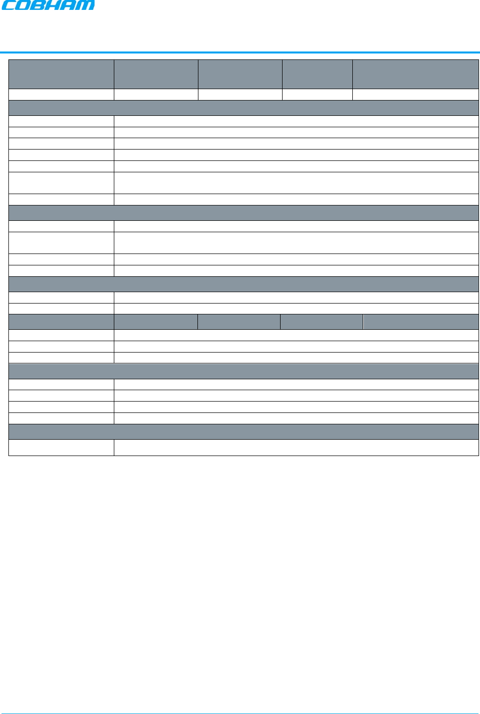
MBF-40 SMR900 PS REPEATER
PRODUCT DESCRIPTION AND USER’S MANUAL
Cobham Wireless – Coverage Date: 31-May-18 www.cobham.com/wireless
Doc. No. 00141UM Rev. 1.0 Page | 61
APPENDIX A – SPECIFICATIONS
Frequency Range Uplink (UL) Downlink (DL) Operational BW
UL/DL Composite Output Power
(*)
SMR900 896-902MHz 929-941MHz 6MHz/12MHz +37 dBm
General Parameters
Noise Figure 3 dB Typical (maximum gain)
Ripple <2dB
Propagation Delay
< 2µs
Gain UL/DL Nominal 66dB, adjustable, in 1dB steps
System Impedance 50Ω
Return loss at antenna
connections
>16dB
Antenna Connectors DIN 7/16, female duplex
Optical Parameters
Wavelength DL/UL
1310/1550nm
Optical output power
(UL) 0dBm
Max optical Loss 10dBo
F/O Connector
SC/APC
Power Specifications
Power Supply
230VAC, 115VAC or -48VDC
Power consumption 140W for single band
Mechanical
Dimensions 21.3” x 15” x 7.8” 540 x 382 x 198mm
Weight Single band: 44.0lbs (20kg)
Enclosure
NEMA 4 (IP 65)
Environmental
EMC
FCC
Operating Temperature -13 to +131ºF (-25 to +55ºC)
Storage Temperature -22 to +158ºF (-30 to +70ºC)
Humidity
ETSI EN 300 019-2-4 (see compliance below)
Complies With
Radio
FCC in accordance with part 90, IC in accordance with RSS131
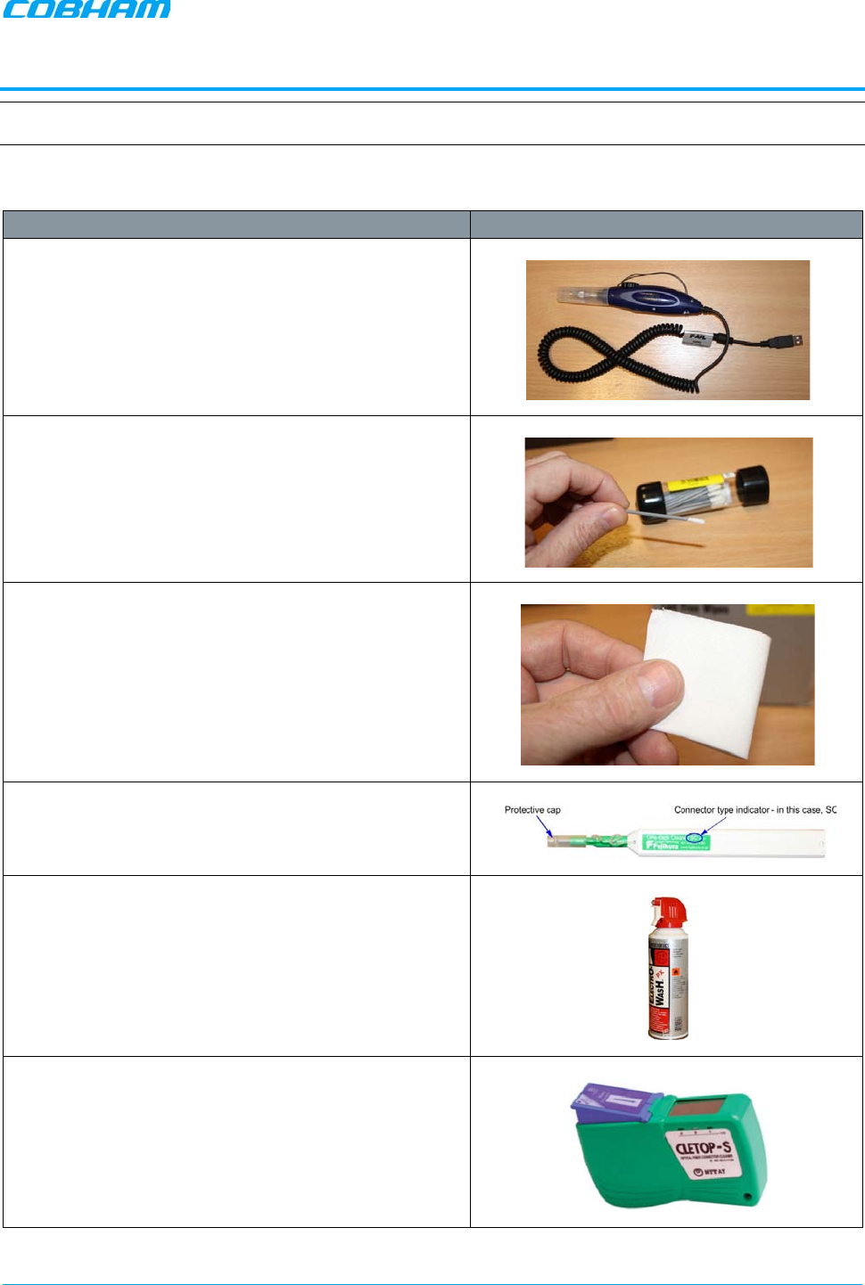
MBF-40 SMR900 PS REPEATER
PRODUCT DESCRIPTION AND USER’S MANUAL
Cobham Wireless – Coverage Date: 31-May-18 www.cobham.com/wireless
Doc. No. 00141UM Rev. 1.0 Page | 62
APPENDIX B – F/O CLEANING PROCEDURE
NOTE: The process is demonstrated on an OMU F/O module and is similar to all F/O equipment supplied by Cobham
Wireless.
Tools
Tool Description Illustration
Fiberscope connected to a PC running the appropriate
viewing software.
It is highly recommended that some form of Fiber
viewing equipment such as a Fiber
scope is used to
ensure that all Fiber
connections are clean before
termination; failure to do so could result in poor system
performance
Lint-free swabs (box), Cobham Wireless P/N 99-000127
Lint-free wipes (pack) Cobham Wireless P/N 99-000125
Fujikura “One Click” cleaner
Cobham Wireless P/N 98-900004.
99% isopropyl alcohol (can), Cobham Wireless P/N 99-
000126
Cletop type S Cassette Cleaner, Cobham Wireless P/N
98-900001
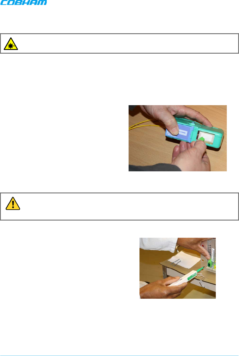
MBF-40 SMR900 PS REPEATER
PRODUCT DESCRIPTION AND USER’S MANUAL
Cobham Wireless – Coverage Date: 31-May-18 www.cobham.com/wireless
Doc. No. 00141UM Rev. 1.0 Page | 63
Dry F/O Cleaning Procedure:
WARNING! Invisible laser radiation might be emitted from disconnected Fibers or connectors. Do not
stare into beams or view directly with optical instruments.
1. Before cleaning the optical connectors on the OMU it is advisable to clean the connector of the mating
cable being attached to the optical port.
An unclean optical connector is often the cause for reduced system performance. A bit of dust or oil
from a finger can easily interfere with, or block light. Fortunately, it is very easy to clean the connector.
Be sure to use the correct procedure for the given connector. When disconnected, cap the SC/APC
connector to keep it clean and prevent scratching the tip of the ferrule.
Use a product specially designed for the
purpose, such as the Cletop type S Cassette
Cleaner.
2. Begin by dry cleaning the F/O bulkhead connector (shown below is the Fujikura One-Click in use).
IMPORTANT!
Always make sure there is a way of inspecting the connector after cleaning. Cleaning can actually leave
the end-face in a worse condition, since alcohol residue is one of the most difficult contaminants to
remove.
3. Remove the protective cap from the cleaning-
head end of the “One Click” cleaner, lift the
protective end-cap on the Fiber connector and
offer-up the end to the Fiber connector
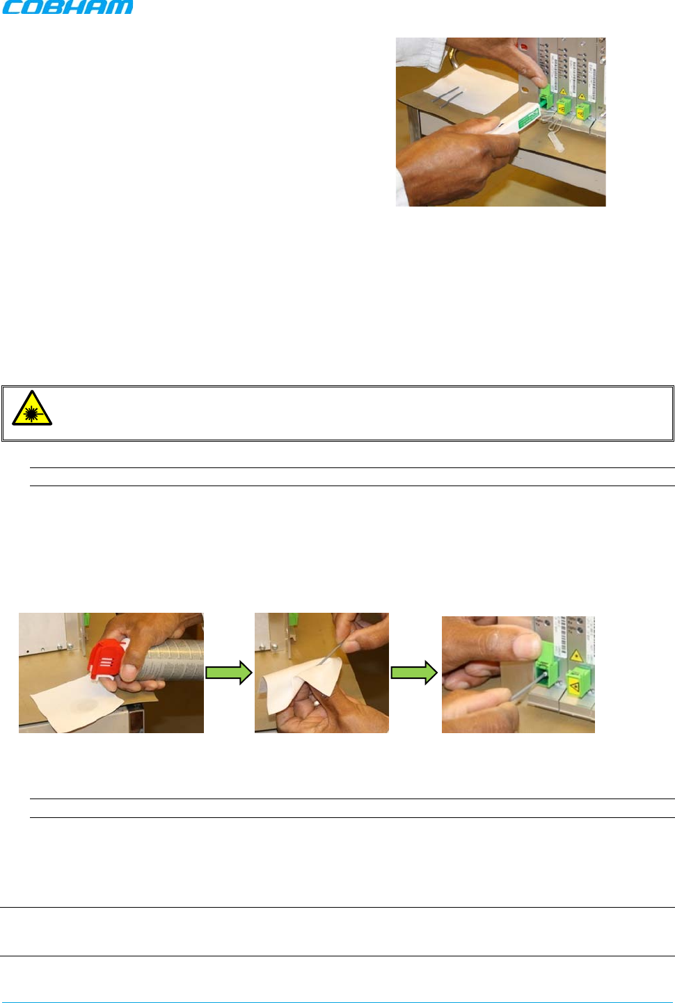
MBF-40 SMR900 PS REPEATER
PRODUCT DESCRIPTION AND USER’S MANUAL
Cobham Wireless – Coverage Date: 31-May-18 www.cobham.com/wireless
Doc. No. 00141UM Rev. 1.0 Page | 64
4. With the cleaning-head end fully engaged in the
connector, push until an audible “click” is heard
5. Without fully withdrawing the cleaning head end
push it in again twice more, each time until an
audible “click” is heard.
6. Withdraw the “One Click” cleaner and replace
the protective end cap.
7. Inspect the Fiber connector using a Fiberscope. On the PC monitor, verify that there is no contamination
present on the connector end-face.
8. If the connector is dirty, clean it with a wet cleaning technique followed immediately by dry cleaning.
This is to remove any remaining residue from the wet clean (the following steps demonstrate a wet
cleaning technique).
Wet F/O Cleaning Procedure
ATTENTION!
Invisible laser radiation might be emitted from disconnected fibers or connectors. Do not stare into
beams or view directly with optical instruments.
1. Lightly moisten a new lint-free wipe with 99% isopropyl alcohol (Step 1 below).
Tip: Have a dry lint-free swab available for immediately drying after performing the wet-cleaning.
2. Lightly press and turn a clean lint-free swab in the moistened area of the wipe to moisten the swab. It is
important that the swab is not too wet (Step 2 below).
3. Insert the moistened lint-free swab into the bulkhead adapter. Lightly press and rotate several times in
the same direction (Step 3 below).
Figure 6-1. Wet-Cleaning Technique
4. Immediately use a dry lint-free swab to clear any remaining alcohol residue.
NOTE: Do not re-use any of the wipes and/or swabs. Dispose of them properly.
5. Follow steps 3 to 6 of dry cleaning above
6. Re-inspect the Fiber using the Fiberscope. On the computer monitor, verify that there is no
contamination present on the connector end-face.
7. If the fibre is still dirty, go back to step 1 (wet cleaning) and repeat the entire process.
NOTE: The entire wet/dry cleaning cycle should only be used twice, if the fiber is still dirty after two cycles of wet/dry
cleaning seek advice from the Cobham Wireless Support Desk.
Step 1
Step 2
Step 3