PCB Piezotronics LDHVM200A Vibration monitor with WIFI User Manual HVM 200 Manual
PCB Piezotronics, Inc. Vibration monitor with WIFI HVM 200 Manual
Users Manual

IHVM200.01 Manual
DRAFT
Larson Davis
HVM200 Manual

DRAFT
Copyright
Copyright 2015 PCB Piezotronics, Inc. This manual is copyrighted, with all rights reserved. The
manual may not be copied in whole or in part for any use without prior written consent of PCB
Piezotronics, Inc.
Trademarks
PCB® is a registered trademark of PCB Group, Inc. Apple Store is a trademark of Apple, Inc. Google
Play is a trademark of Google, Inc. All other trademarks are property of their respective owners.
Disclaimer
The following paragraph does not apply in any state or country where such statements are not
agreeable with local law:
Even though PCB Piezotronics, Inc. has reviewed its documentation, PCB Piezotronics, Inc. makes no
warranty or representation, either expressed or implied, with respect to this instrument and
documentation, its quality, performance, merchantability, or fitness for a particular purpose. This
documentation is subject to change without notice, and should not be construed as a commitment or
representation by PCB Piezotronics, Inc.
This publication may contain inaccuracies or typographical errors. PCB Piezotronics, Inc. will
periodically update the material for inclusion in new editions. Changes and improvements to the
information described in this manual may be made at any time.
Recycling
PCB Piezotronics, Inc. is an environmentally friendly organization and encourages our customers to
be environmentally conscious. When this product reaches its end of life, please recycle the product
through a local recycling center or return the product to:
PCB Piezotronics, Inc.
Attn: Recycling Coordinator
1681 West 820 North
Provo, Utah, USA 84601-1341
where it will be accepted for disposal.
Warranty
For warranty information, refer to our Terms and Conditions of Sale on our website at
www.larsondavis.com/TermsConditions.aspx.
HVM200 Purchase Information
Record the serial number and date of purchase below.
Serial Number:_______________________ Date of Purchase:____________________
HVM200 Manual Introduction 1-1
CHAPTER
1Introduction
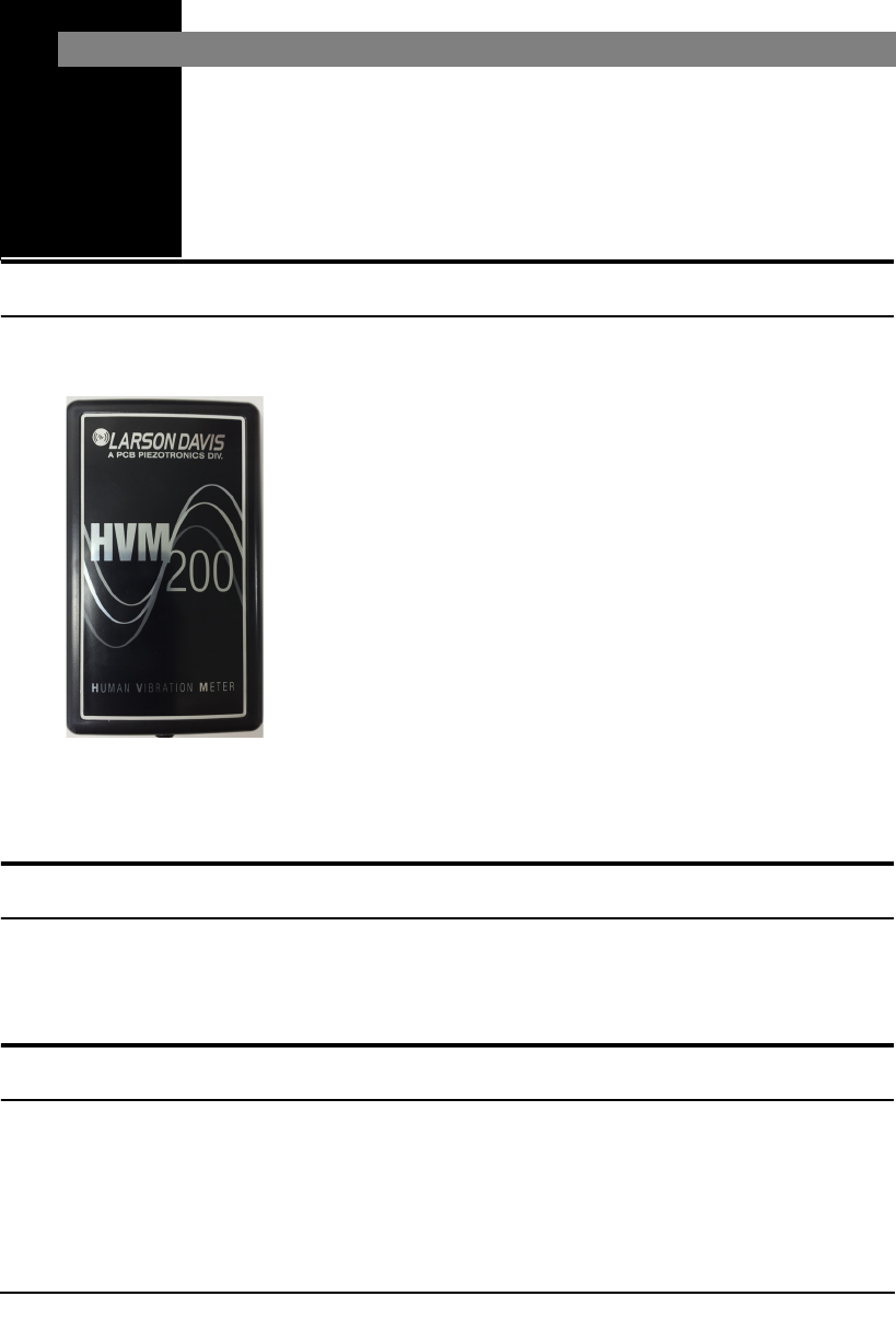
This chapter presents an overview of the HVM200
Human Vibration Meter.
Features
The Larson Davis HVM200 Human Vibration Meter is a
Type 1 instrument designed for use in assessing vibration as
perceived by human beings.
The HVM200 provides the following features for vibration
measurement:
• Whole body, hand-arm, and general vibration
applications
• Wireless mobile interface
• Compact design for easy wear and convenient placement
• Mobile G4 measurement application for configuring,
measuring, and viewing vibration data on multiple
meters
• Connection and control of multiple meters through Wi-Fi
access (
• Support for optional 1/1 and 1/3 Octave Band Analysis
• Support for full SLM Utility G4 Software analysis
Standard Accessories
• USB 2.0 to Micro-USB power and communications
cable
• Removable 64 GB SD memory
Optional Accessories
• 1/1 and 1/3 Octave Band Analysis firmware
• SLM Utility G4 for HVM Software
• Larson Davis PSA035 Power Supply

1-2 Transducer Selection HVM200 Manual
• Larson Davis CCS048 Arm Band for wearing the
HVM200
• Larson Davis SEN041F accelerometer for Hand-Arm
vibration measurements
• Larson Davis SEN020 accelerometer for Hand-Arm and
general vibration measurements
• Larson Davis SEN027 Seat Adapter, accelerometer, and
adapter for whole-body vibration measurements
• Larson Davis ADP063, ADP080A, ADP081A, and
ADP082A adapters for accelerometer placement
Optional Larson Davis CCS047
Hard Shell Case
• Larson Davis CBL210-05, CBL216, and CBL217-01
cables for connection between accelerometers and
HVM200 meter.
• Larson Davis 394C06 Hand-held Shaker for vibrational
measurement verification
• Larson Davis CCS047 Hard Shell Case for transport and
protection of HVM200 and accessories
Transducer Selection
The HVM200 requires a transducer to convert physical
vibration quantities into measurable, electrical signals. In
selecting a transducer for the HVM200, consider the
following
ICP® or Charge Accelerometers
The HVM200 has built-in ICP®
power supplies and charge
amplifiers. This allows the HVM200
to interface directly with ICP or
charge transducers, and eliminates
the need for external signal
conditioning.
•ICP
accelerometers are also called “Voltage Mode” or
“Low impedance” and may be known by various other
vendor trade names. ICP is PCB’s registered trademark
which stands for “Integrated Circuit Piezoelectric” and
identifies PCB sensors which incorporate built-in, signal
conditioning electronics. The built-in electronics serve to
convert the high impedance charge signal that is
generated by the piezoelectric sensing element to a
usable low impedance voltage signal which can be
readily transmitted over ordinary 2 wire or coaxial cables
to any voltage readout or recording device. The low
impedance signal can be transmitted over long cable
distances and used in dirty field or factory environments
with little signal degradation

HVM200 Manual Transducer Selection 1-3
The HVM200 could also be utilized
through an alternative direct input.
This would require, however, the use
of some kind of external signal
conditioning unit such as an external
source of ICP power, or an external
charge amplifier.
• Charge mode sensors output a high impedance, electrical
charge signal that is generated by the piezoelectric
sensing element. This signal is extremely sensitive to
corruption from environmental influences. To conduct
accurate measurements, it is necessary to condition this
signal to a low impedance voltage before it can be input
to a readout or recording device. A charge amplifier or
in-line charge converter is generally used for this
purpose.
Transducer Sensitivity
With accelerometers, the proper sensitivity depends on the
application being performed. If the application is a high
vibration level application, a low sensitivity should be
selected. For low vibration level applications, a high
sensitivity accelerometer should be used.
Transverse sensitivity may also affect measurements. It is
defined as the unwanted output signal of a motion sensor
when subjected to motion perpendicular to the sensitive
axis. This is usually expressed as a percent of the normal
axis sensitivity. For example if you are using a tri-axial
accelerometer and place an input signal on the Z axis, your
X axis could also be reading a level even though there is
really no x-axis signal present.
Resonant Frequency
The resonant frequency is defined as the frequency at which
the structure will readily vibrate. For accelerometers, there is
one frequency at which the accelerometer vibrates much
easier than at other frequencies. At this point, the reading
will be very high, and could overload the input of the
HVM200. However, for most of the recommended
accelerometers, the resonant frequency is well above the
upper limit of the HVM200, and will subsequently be
masked out by the low pass filter on the HVM200. If the
resonant frequency becomes an issue, it is recommended
that an external mechanical filter be used.
Frequency Range
Most recommended accelerometers will have a frequency
range sufficient for use with the HVM200. Refer to the

1-4 Transducer Selection HVM200 Manual
frequency response tables and graphs in this manual for
more information on the HVM200 frequency response.
Environmental Effects
Consider temperature, humidity, and other physical agents,
such as mounting surface, mounting method, mass, and
environment. The mass of the accelerometer should ideally
be no more that 1/50 of the mass of the object being
measured. A ratio of as little as 1/10 is acceptable in extreme
circumstance
HVM200 Manual Getting Started 2-1
CHAPTER
2Getting Started
This chapter provides instructions for setting up and
configuring HVM200 meters for use with the G4App.
Unpacking the HVM200
The HVM200 package includes a USB to mirco-USB cable
with the meter. After removing the HVM200 and cable from
the packaging, record the serial number and date of purchase
in a safe place where it can be retrieved, in case you require
customer support.
Powering the HVM200
Before using your HVM200, you should charge the battery
completely by following these steps:
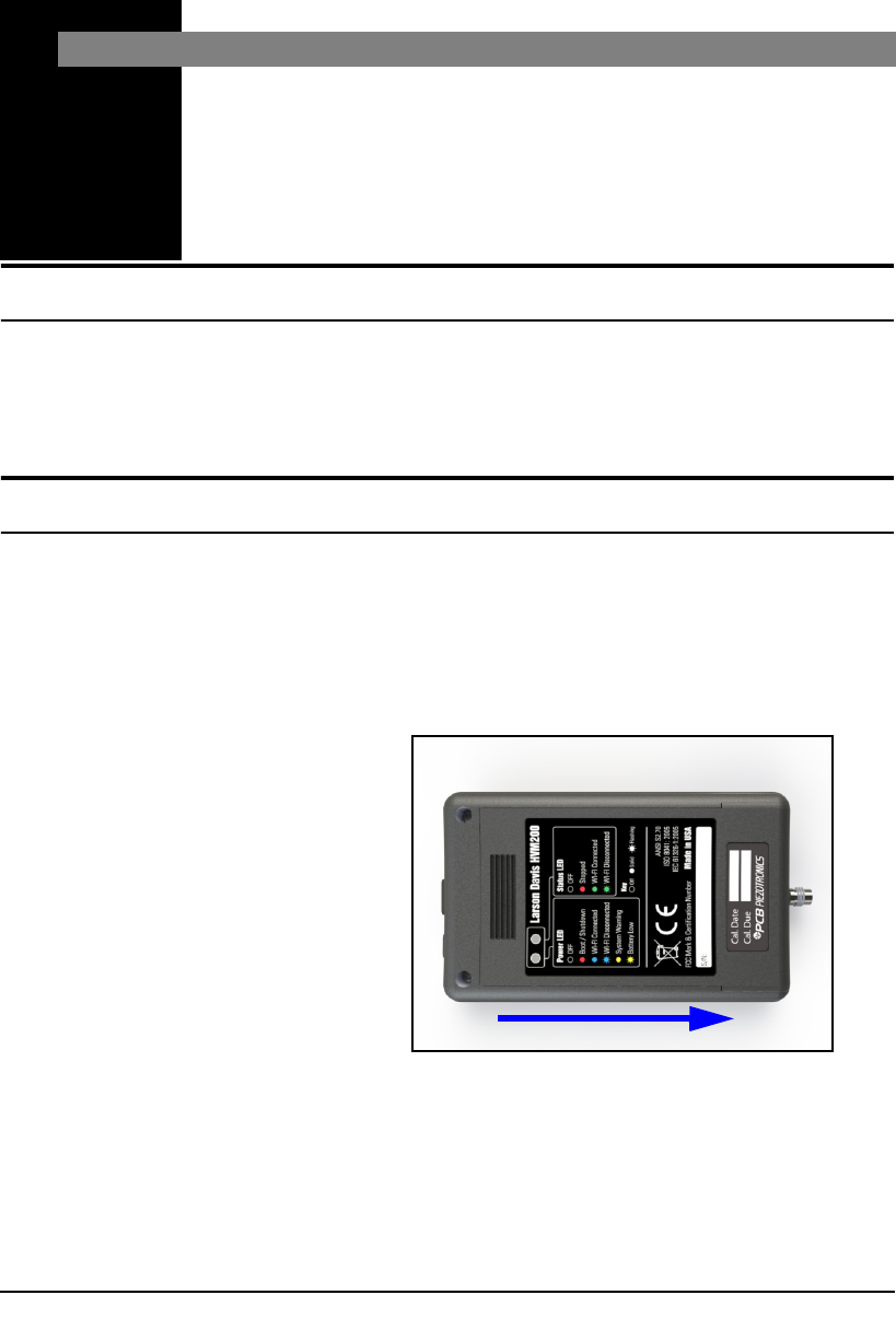
Step 1 Slide and remove the back battery cover from the
HVM200 meter.
FIGURE 2-1 Remove Battery Cover
Step 2 Insert the supplied battery into the HVM200 so that
the battery contacts align with the power contacts
in the device.
Step 3 Slide the back battery cover onto the HVM200.
2-2 Downloading the HVM200 App HVM200 Manual
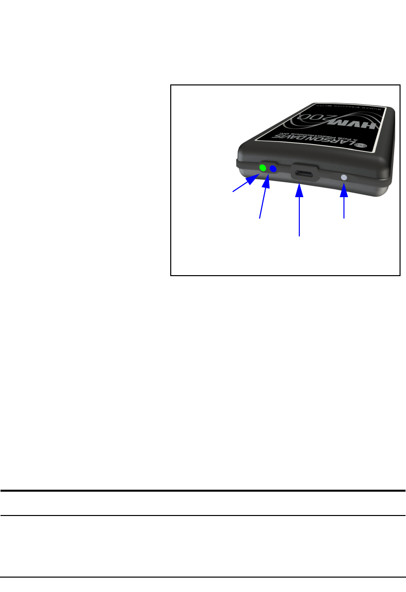
Step 4 Connect one end of the supplied cable to the
HVM200 micro-USB port and the other end to a
powered USB port.
The Power LED displays a yellow
color while charging. If the LED
does not show any color, push the
power button in for a few seconds.
FIGURE 2-2 HVM200 Micro-USB Port
Refer to the back label of your
HVM200 for a description of each
LED indication.
Step 5 Make sure the HVM200 is fully charged before
performing any operations. When fully charged,
the Power LED displays a solid green (not
blinking) color. This may take up to 6 hours,
depending on the type of USB port used to charge
the device.
Step 6 Once fully charged, allow the battery to
completely drain with HVM200 usage in the first
cycle before recharging. This allows the battery
power display in the software to more accurately
reflect battery life. After completing the first
cycle, avoid leaving the battery drained for
extended periods of time. This will maximize
overall battery life.
Downloading the HVM200 App
Once your HVM200 is fully charged, use your mobile
device to find and download the HVM200 app from Google
Play or the Apple Store®.
Power LED
Status LED Power Button
Micro-USB
port
HVM200 Manual Connecting to a Wi-Fi Network 2-3
Connecting to a Wi-Fi Network
To establish a Wi-Fi connection with the HVM200 meter,
follow these steps:
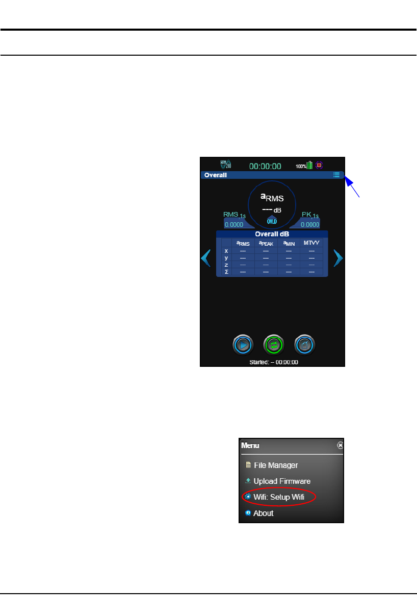
Step 1 Launch the HVM App.
Step 2 Click the menu icon, as shown in Figure 2-3.
FIGURE 2-3 HVM200 App
Step 3 On the HVM200 Menu, select Setup Wi-Fi.
FIGURE 2-4 Wi-Fi Setup
Menu
Icon
2-4 Connecting to a Wi-Fi Network HVM200 Manual
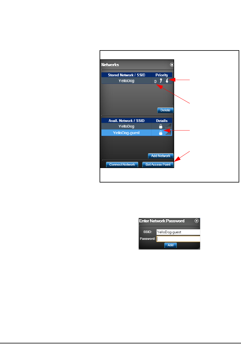
Step 4 If no stored networks appear in the Networks
dialog box, select an available network and click
Add Network.
If you have already entered a
password and a stored network
appears, select it and click Connect
Network.
FIGURE 2-5 Networks Settings
Larson Davis recommends using
secure Wi-Fi networks with your
HVM200 meter.
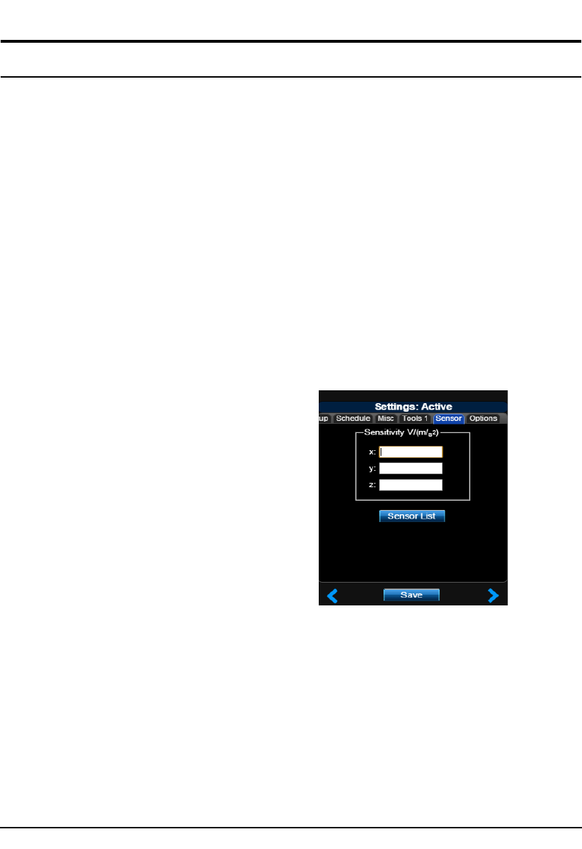
Step 5 Enter the network password, if required, and click
Add.
With multiple stored networks, you
can establish a connection order by
assigning a priority number to the
network. An automatic connection is
first made to the network with the
highest priority. If multiple stored
networks have the same priority
number, an automatic connection is
made with the network displayed
higher on the list.
FIGURE 2-6 Enter Network Password
Step 6 Select the stored network and click Connect.
Step 7 Assign a connection priority value for the
network, if needed.
Step 8 If no network is available, click Set Access Point.
This enables the HVM200 to transmit and receive
data through Wi-Fi to your mobile device.
Click the up or down
arrow to raise or lower
the priority of the
network connection.
Secure network requires
password.
Higher numerical values
establish higher priority
in connection sequence.
If no network is
available, click to
transmit and receive data
through Wi-Fi from the
HVM200 to a mobile
device.
HVM200 Manual Connecting the Accelerometer 2-5
Connecting the Accelerometer
Refer to the "Introduction" in this
manual for information on selecting
the proper accelerometer for the
HVM200 meter.
To connect the accelerometer to your HVM200 meter,
follow these steps:
Step 1 Insert the accelerometer cable into the 4-pin
connector on the HVM200 and then screw it tight.
Step 2 Insert the other end of the accelerometer cable into
the 4-pin connector on the accelerometer and then
screw it tight.
Step 3 If the HVM200 is not already turned on, press the
power button.
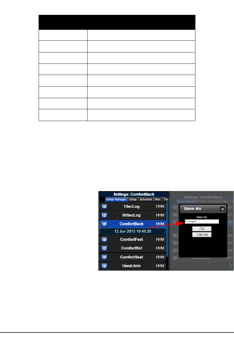
Step 4 Open the Setup Manager in the HVM200 App and
click the Sensor tab.
If you are using an accelerometer
with Transducer Electronid Data
Sheet (TEDS) capabilities, the
sensitivity values will already be
displayed for the x, y, and z axes of
the sensor.
FIGURE 2-7 Sensor Tab
Step 5 Click Sensor List.

2-6 Connecting the Accelerometer HVM200 Manual
Sensor information, including
model, serial number, and sensitivity
specifications are usually listed on
the calibration certificate that comes
with an accelerometer.
FIGURE 2-8 Sensor List Identification and
Sensitivity
If you are using an accelerometer
with TEDS capabilities, sensor
information will appear
automatically in this list.
In the Sensor List, type the model, serial number of your
accelerometer, and the sensitivity for the x, y, and z axes and
then click Add.
Select the accelerometer when it appears in the list and click
Select. The sensitivity values will automatically appear on
the Sensor tab. Click Save.
Use the Sensor List to quickly access and select stored
sensors for future measurements.

HVM200 Manual Making a Measurement 3-1
CHAPTER
3Making a Measurement
This chapter provides an example procedure for
performing a vibration measurement with the HVM200
meter and the HVM200 App.
Overview
The following example demonstrates procedures for
measuring vibration, including:
• Setting Up the Measurement
• Making the Measurement
• Downloading the Measurement Data
Setting Up the Measurement
To set up the measurement:
1. Perform a calibration check.
2. Specify a setup file on your mobile device.
The following sections describe these steps in more detail.
Perform a Calibration Check
Performing a calibration check tests the circuitry of the
HVM200 to verify that all functions are working. To
perform a calibration check:
Specify a Setup File on Your Mobile Device
The HVM200 App includes nine default setups on its
Settings list. These default setups correspond to settings
typically used for different methods of measurement.
Default Setup Application
1secLog
Table 3-1 HVM200 Default Setups
3-2 Setting Up the Measurement HVM200 Manual
You can also create new setup files on the Settings list. To
create a new setup file, follow these steps:
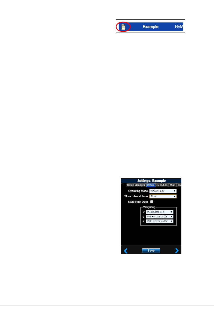
Name the Setup File
The easiest way to create a new
setup file is to modify an existing
default setup and save it with a
different name.
Step 1 Right-click on a default setup file in the Settings
list. Select Save As and specify the setup name.
FIGURE 3-1 Name the Setup File
If you return to the Setup Manager
tab from a settings tab, you are
prompted to save settings. Click Ye s
to apply the changes to the setup.
Step 2 Find and click the setup file you just created. The
list now displays a report icon next to your new
setup file.
60secLog
ComfortBack
ComfortFeet
ComfortRot
ComfortSeat
Hand-Arm
HealthSeat
WmBuilding
Default Setup Application
Table 3-1 HVM200 Default Setups
HVM200 Manual Setting Up the Measurement 3-3
FIGURE 3-2 Select New Setup File
Set Operating Mode, Interval Time, and Weighting
The interval time values represent
the span that data is collected,
averaged, and stored before starting
a new sample. The Slow option is an
exponential detector, meaning that
each 1 second average computation
includes all previous data in the
measurement.
Step 3 On the Setup tab, specify any changes to your
settings and select the Store Raw Data option if
you have the it installed and need it for your post-
measurement analysis. The Store Raw Data option
will greatly increase the amount of memory
required to store the measurement. Click Save.
The supplied HVM200 memory card
can store up to 24 hours of
measurements with the Store Raw
Data option enabled. When not
enabled, the card can store
approximately 8000 hours of
measurements.
The Wh weighting is automatically
specified for all axes with the Hand/
Arm mode. For more information on
operating mode options and
weighting curves, see the "Technical
Specifications" in this manual and
ISO 8041:2005.
FIGURE 3-3 Operation Settings
3-4 Setting Up the Measurement HVM200 Manual
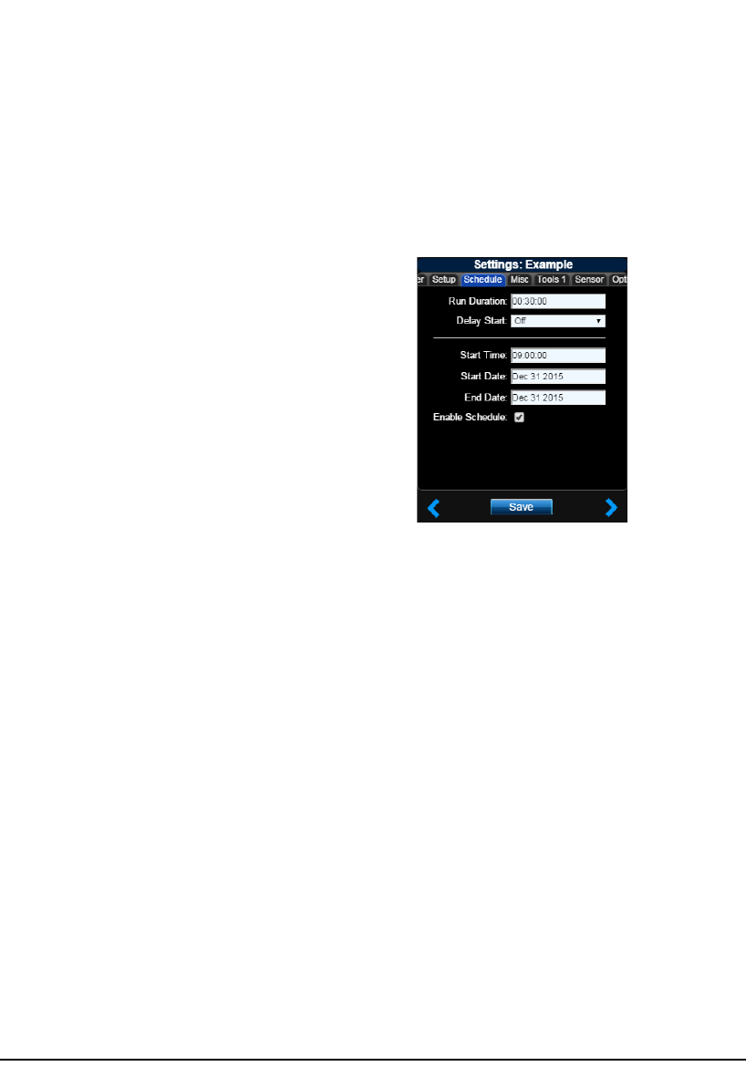
Set Measurement Schedule
Step 4 If needed, schedule the HVM200 to take a
measurement automatically by selecting the
Enable Schedule option on the Schedule tab.
Specify the Start Date and Start Time, as well as
the End Date and Duration. Specify a Delay
Start, if needed. Click Save.
FIGURE 3-4 Schedule Settings
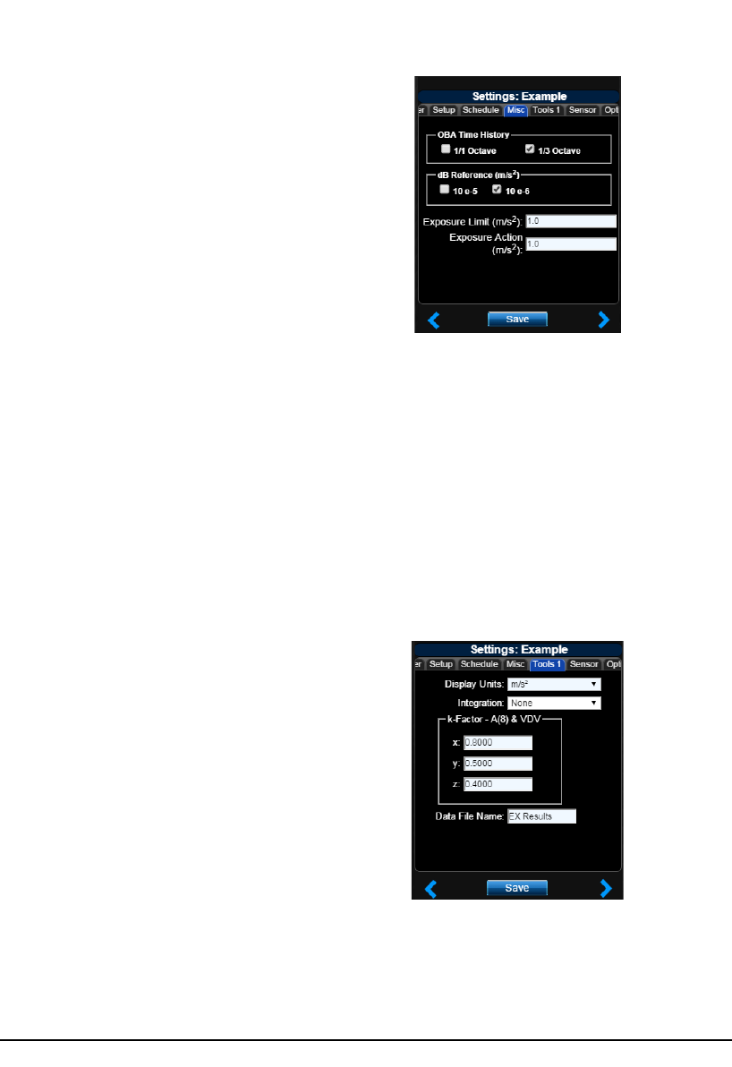
Set OBA Time History, Decibel Reference, and Exposure Settings
The dB Reference options are
applicable only if you have selected
to display acceleration, velocity, or
displacement in decibels on the
Tools tab; otherwise, the dB
Reference selection is ignored.
Step 5 On the Misc tab, select 1/1 Octave or 1/3 Octave
to include octave band analysis in your
measurement data, if you have the options
installed. Select 10e-5 or 10e-6 as the dB
Reference, and specify the exposure settings. Click
Save.
HVM200 Manual Setting Up the Measurement 3-5
The exposure settings show default
values according to the EU Physical
Agents Directive (2002/44/EC) but
can be modified according to
differing standards or needs.
FIGURE 3-5 Misc. Settings
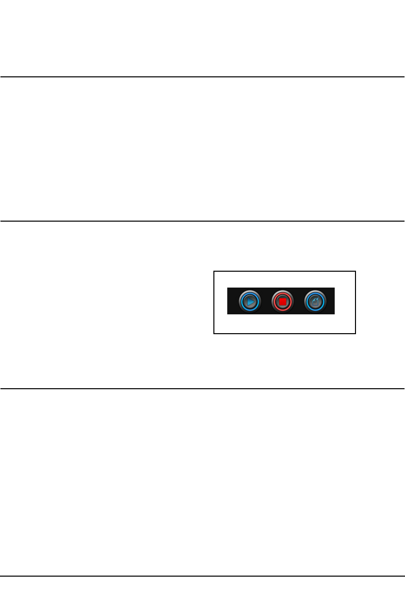
Choose Tools Settings
If you are connected to multiple
meters, the HVM200 App displays a
Tools tab for each meter, according
to their numbered order.
Single integration calculations
convert acceleration values into
velocity values; double integration
converts acceleration values into
displacement values. Display units
may be converted to match
integration results if not specified
correctly. Integration is applicable
only to the Vibration mode.
Step 6 On the Tools tab, choose the Display Units and
Integration method. Specify the k-Factor for
each axis and type a Data File Name. Click Save.

3-6 Making the Measurement HVM200 Manual
The HVM200 multiplies the specified
k-Factor by the instantaneous
acceleration for each axis to produce
the summation ( value on the
HVM200 App.
FIGURE 3-6 Tools Settings
Verify Sensor Settings
If you are using an accelerometer with TEDS capability, the
Sensor tab settings are automatically specified. If your
accelerometer does not have TEDS capability and you have
not already specified the settings, refer to the section
"Transducer Selection".
Verify Installed Options
If you have purchased Octave Band Analysis or Raw Data
options, click the Options tab and verify that they are
displayed and selected in the list.
Making the Measurement
To make the vibration measurement:
When using the HVM200 for
vibration measurements, ensure that
the ambient temperature during
operation does not exceed 50 °C
(122° F).
1. Position the HVM200 meter and accelerometer.
2. Start the measurement.
3. Observe data.
4. Stop and annotate the measurement.
The following sections describe these steps in more detail.
Position for Hand/Arm Vibration
For Hand/Arm vibration measurement, follow these steps:
Step 1 Attach the Larson Davis CCS048 Arm Band on
the person being monitored. The end with the
transparent cover should be the farthest from the
hand.
Step 2 Insert the HVM200 into the arm band so that the
accelerometer connector is nearest the hand.
HVM200 Manual Making the Measurement 3-7
Refer to the seciton "Transducer
Selection" for more information.
Step 3 Connect the accelerometer to the HVM200.
Step 4 Attach the accelerometer to an appropriate adapter.
Position for Whole Body Vibration with Seat Adapter
For whole body vibration measurements using the Larson
Davis SEN027 Seat Adapter, follow these steps:
The Seat Adapter is sold with the
SEN027 accelerometer already
housed within the adapter and with
the cable already connected to the
accelerometer.
Step 1 Place the seat adapter in the location where the
person being monitored will sit.
Step 2 Connect the accelerometer cable to the HVM200.
Step 3 Set the HVM200 meter in a secure location, where
it will not fall from its position.
Start the Measurement
Click the Start button that appears on all HVM200 App
displays.
FIGURE 3-7 Start, Stop, or Annotate the
Measurement
Observe Data
The HVM200 App provides the following data displays:
Alternatively, you can also schedule
measurements automatically on the
Schedule tab if you do not need to
observe them.
• Overall
• Summation
•X-axis
Start Stop Annotate
3-8 Making the Measurement HVM200 Manual
•Y-axis
•Z-axis
To advance from one data display to the next, click the Next
Arrow. To enlarge a data display, click the Zoom button.
The Overall display shows cumulative data for all three
axes and their summation for the measurement.
FIGURE 3-8 Overall Data Display
represents the summation of
vibration values taken from the X, Y,
and Z axes.
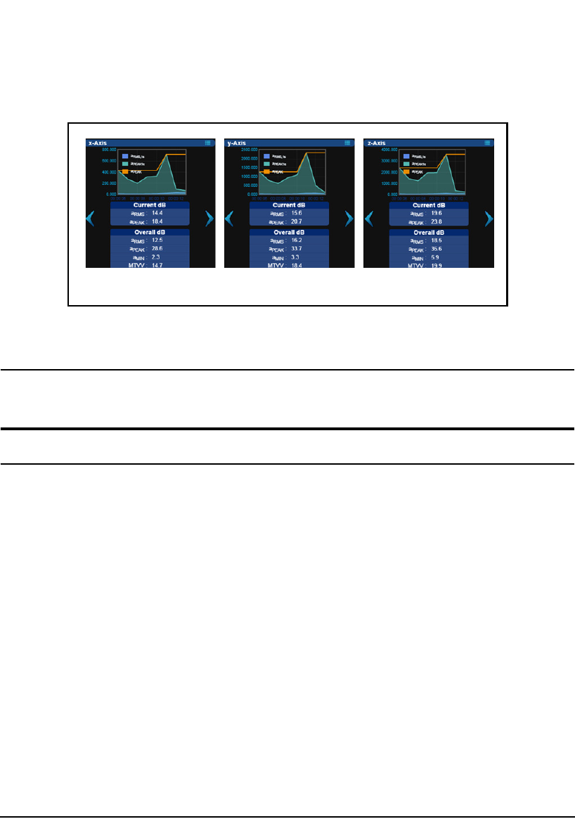
The Summation display provides a real-time graphical
representation of the current summed values from all three
axes.
Current overall root mean
square (RMS) vibration
value according to specfied
units.
Measurement
Duration Clock
RMS value from the
previous second
Overloaded Indicator
Values for each axis
Summation values
Next data display
arrow
Battery Status RMS: Root mean square value
PEAK (PK): Highest value
MIN: Lowest value
MTVV: Maximum Transient
Vibration Value, or Vibration
Dose Value (VDV)
Vibration values according
to specified units
Measurement Time
Current summed RMS value
Current summed PEAK value
Overall data for each display
HVM200 Manual Downloading the Data 3-9
FIGURE 3-9 Summation Data Display
The Axis displays provide real-time graphical
representations of current values for each axis.
FIGURE 3-10 X, Y, and Z Axis Data Displays
Stop and Annotate the Measurement
Click the Stop button and, if needed, click the Annotate
button to provide a note to include with the measurement.
Downloading the Data
Once the measurement is completed, you can download data
as raw data or with a third-party tool.
XYZ

3-10 Downloading the Data HVM200 Manual

HVM200 Manual Technical Specifications A-1
APPENDIX
ATechnical Specifications
Specifications are subject to change without notice. Numerical values given are typical. Refer to
specific calibration or test results for accurate data on a specific unit.
Functions Measured
General Characteristics
Real-time Clock/Calendar
• Accuracy: 0.02% (-10° C to 50° C)
• 24 hour clock: hh:mm:ss
Run-time Clock
• One second resolution
• Format: hh:mm:ss
• Maximum run time: 99:59:59
Mode Data Buffer Measurements Time History Buffer Measurements
Vibration Arms, Amin, Amax, Amp, Peak, Aeq,
PE
Arms with optional Peak
Hand Arm Arms, Amin, Amax, Amp, Peak, Aeq,
A(1), A(2), A(4), A(8), A(8) Exposure,
PE
Arms with optional Peak
Whole Body Arms, Amin, Amax, Amp, Peak, Aeq,
CFmp, CF, VDV,PE
Arms with optional Peak

A-2 Physical Characteristics HVM200 Manual
Effects of Temperature
The RMS level varies 0.5 dB when the complete instrument is tested over the - 10° C to 50° C
temperature range. The reference reading, for this test, is taken at 20° C and 36% relative humidity
(RH); the input signal is at 79.6 Hz.
Effects of Humidity
The RMS level varies 0.5 dB when the complete instrument is tested over the 0% to 90% RH,
noncondensing range. This test is performed at 40° C, with an input signal of 79.6 Hz.
Limits of Temperature and Humidity
Permanent damage can occur when stored or operated above 60° C or below -20° C.
Effects of Magnetic Fields
The RMS level varies 0.5 dB when the complete instrument is tested in an 80 A/m, 60 Hz magnetic
field (worst case orientation).
Effects of Mechanical Vibrations
The instrument meets the specifications for susceptibility to vibration in accordance with ISO
8041:2005(E) section 7.1.
Stabilization Time
At power-on, allow the instrument to stabilize, approximately 20 seconds, prior to performing any
measurements. When changing sensors, allow 10 seconds of stabilization time prior to performing a
new measurement.
Physical Characteristics
Dimensions/Weight
• Length: 4.6 inches (11.8 cm)
• Width: 2.6 inches (6.7 cm)
• Depth: 0.7 inches (1.8 cm)
• Weight: 4.6 ounces (130 grams) - including battery
Data Storage
• Removable micro SD memory card up to 64 GB.

HVM200 Manual Data Communication CharacteristicsA-3
• 2 GB file size limit. No limit to number of files or setups.
• No limit to number of files or setups
• 5 minute (typical) data retention for clock during battery change
• Data and settings are stored in non-volatile memory
Data Rate
• USB 2.0 hi-speed
• Data rate > 1 MBps
• Wi-Fi 802.11 b/g
Connections
• Input: 1/4-28 4-pin male
• Charging and communicaiton: Micro USB
Data Communication Characteristics
Need specs.
SSID Connection:
Bandwidth Consumption:
USB effects:
FCC Wi-Fi Characteristics:
Maximum Data Rate:
Electrical Characteristics
Power Consumption
Need specs
Power Supply
• User replaceable 2100 mAh rechargeable Lithium-ion battery
• Operation time > 12 hours
• Battery life is maintained at 80% after 2 weeks without operation
• External Power: Micro USB cable or Larson Davis Power Supply PSA035

A-4 Adaptor Resonances and Frequency Responses HVM200 Manual
Power Usage/Storage
Need specs.
Swapping Limitations
Device must be off while replacing Micro SD card or battery.
Adaptor Resonances and Frequency Responses
Need specs
Reference Values
Reference Acceleration
The reference acceleration (for displaying data in dB) is 10-6 m/s2. the user can also select a reference
of 10-5 m/s2 (see section 4-3 of the manual for an explanation of how to select the reference
acceleration.)
Reference Calibration Frequency
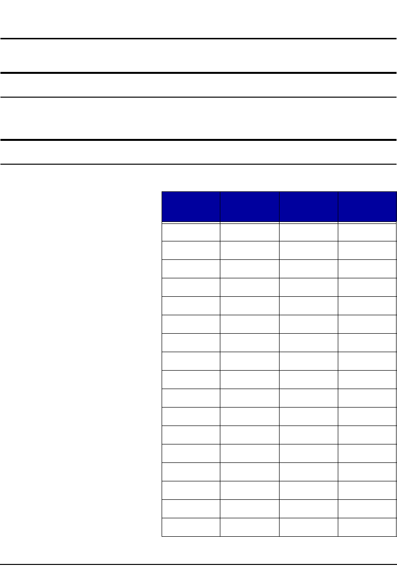
Operating Mode Frequency Weighting Reference Calibration
Frequency
Vibration Fa (0.4 Hz to 100 Hz)
Wf (Severity)
Fb (0.4 Hz to 1250 Hz)
Fc (6.3 Hz to 1250 Hz)
7.96 Hz
79.6 Hz
Hand Arm Wh 79.6 Hz
Whole Body Wm
Wb
Wc
Wd
We
Wg
Wj
Wk
7.96 Hz
HVM200 Manual Typical Measurement Ranges A-5
Reference Calibration Vibration
The reference calibration vibration is 1 m/s2
Typical Measurement Ranges
Need specs for all filters. In both mv/g and dB?
Frequency Weighting Curves
Fa (Flat 0.4 Hz to 100 Hz)
Freq ( Hz)
Nominal
Freq ( Hz)
True
Fa dB Tolerance
dB
0.100 0.1000 -24.10 +2/-
0.125 0.1259 -20.12 +2/ -
0.160 0.1585 -16.19 +2/ -
0.200 0.1995 -12.34 +2/-
0.250 0.2512 -8.71 +2/-2
0.315 0.3162 -5.51 +2/-2
0.400 0.3981 -3.05 +1/-1
0.500 0.5012 -1.48 +1/-1
0.630 0.6310 -0.65 +1/-1
0.800 0.7943 -0.27 +1/-1
1.00 1.000 -0.11 +1/-1
1.25 1.259 -0.04 +1/-1
1.60 1.585 -0.02 +1/-1
2.00 1.995 -0.01 +1/-1
2.50 2.512 0.00 +1/-1
3.15 3.162 0.00 +1/-1
4.00 3.981 0.00 +1/-1

A-6 Frequency Weighting Curves HVM200 Manual
5.00 5.012 0.00 +1/-1
6.30 6.310 0.00 +1/-1
8.00 7.943 0.00 0
10.0 10.00 0.00 +1/-1
12.5 12.59 0.00 +1/-1
16.0 15.85 0.00 +1/-1
20.0 19.95 -0.01 +1/-1
25.0 25.12 -0.02 +1/-1
31.5 31.62 -0.04 +1/-1
40.0 39.81 -0.11 +1/-1
50.0 50.12 -0.27 +1/-1
63.0 63.10 -0.64 +1/-1
80.0 79.43 -1.46 +1/-1
100 100.0 -3.01 +1/-1
125 125.9 -5.46 +2/-2
160 158.5 -8.64 +2/-2
200 199.5 -12.27 +2/ -
250 251.2 -16.11 +2/ -
315 316.2 -20.04 +2/ -
400 398.1 -24.02 +2/ -
Freq ( Hz)
Nominal
Freq ( Hz)
True
Fa dB Tolerance
dB

HVM200 Manual Frequency Weighting Curves A-7
Fb (Flat 0.4 Hz to 1260 Hz) Frequency Weighting
Freq ( Hz)
Nominal
Freq ( Hz)
True
Fb dB Tolerance
dB
0.100 0.1000 -24.10 +2 / -
0.125 0.1259 -20.12 +2 / -
0.160 0.1585 -16.19 +2 / -
0.200 0.1995 -12.34 +2 / -
0.250 0.2512 -8.71 +2 / -2
0.315 0.3162 -5.51 +1 / -1
0.400 0.3981 -3.05 +1 / -1
0.500 0.5012 -1.48 +1 / -1
0.630 0.6310 -0.65 +1 / -1
0.800 0.7943 -0.27 +1 / -1
1.00 1.000 -0.11 +1 / -1
1.25 1.259 -0.04 +1 / -1
1.60 1.585 -0.02 +1 / -1
2.00 1.995 -0.01 +1 / -1
2.50 2.512 0.00 +1 / -1
3.15 3.162 0.00 +1 / -1
4.00 3.981 0.00 +1 / -1
5.00 5.012 0.00 +1 / -1
6.30 6.310 0.00 +1 / -1
8.00 7.943 0.00 +1 / -1
10.0 10.00 0.00 +1 / -1
12.5 12.59 0.00 +1 / -1
16.0 15.85 0.00 +1 / -1
20.0 19.95 0.00 +1 / -1
25.0 25.12 0.00 +1 / -1

A-8 Frequency Weighting Curves HVM200 Manual
31.5 31.62 0.00 +1 / -1
40.0 39.81 0.00 +1 / -1
50.0 50.12 0.00 +1 / -1
63.0 63.10 0.00 +1 / -1
80.0 79.43 0.00 0
100 100.0 0.00 +1 / -1
125 125.9 0.00 +1 / -1
160 158.5 0.00 +1 / -1
200 199.5 0.00 +1 / -1
250 251.2 -0.01 +1 / -1
315 316.2 -0.02 +1 / -1
400 398.1 -0.04 +1 / -1
500 501.2 -0.11 +1 / -1
630 631.0 -0.27 +1 / -1
800 794.3 -0.64 +1 / -1
1000 1000 -1.46 +2 / -2
1250 1259 -3.01 +2 / -2
1600 1585 -5.46 +2 / -2
2000 1995 -8.64 +2 / -2
2500 2512 -12.27 +2 / -
3150 3162 -16.11 +2 / -
4000 3981 -20.04 +2 / -
5000 5012 -24.02 +2 / -
6300 6310 -28.01 +2 / -
8000 7943 -32.00 +2 / -
10000 10000 -36.00 +2 / -
Freq ( Hz)
Nominal
Freq ( Hz)
True
Fb dB Tolerance
dB

HVM200 Manual Frequency Weighting Curves A-9
Fc (Flat 6.3 Hz to 1260 Hz), Wh, and Wf Frequency Weighting.
Freq ( Hz)
Nominal
Freq ( Hz)
True
Fc dB Wh dB Tolerance
dB
Wf dB Tolerance
dB
0.800 0.7943 -36.00 -36.00 +2 / --76.00 +4 / -
1.00 1.000 -32.00 -31.99 +2 / --68.00 +4 / -
1.25 1.259 -28.01 -27.99 +2 / --60.00 +4 / -
1.60 1.585 -24.02 -23.99 +2 / --52.00 +4 / -
2.00 1.995 -20.04 -20.01 +2 / --44.00 +4 / -
2.50 2.512 -16.11 -16.05 +2 / --36.00 +4 / -4
3.15 3.162 -12.27 -12.18 +2 / --28.00 +4 / -4
4.00 3.981 -8.64 -8.51 +2 / -2 -19.90 +4 / -4
5.00 5.012 -5.46 -5.27 +2 / -2 -12.20 +4 / -4
6.30 6.310 -3.01 -2.77 +2 / -2 -5.30 +4 / -4
8.00 7.943 -1.46 -1.18 +2 / -2 -1.50 +4 / -4
10.0 10.00 -0.64 -0.43 +1 / -1 0.00 +1 / -2
12.5 12.59 -.027 -0.38 +1 / -1 0.00 +1 / -2
16.0 15.85 -0.11 -0.96 +1 / -1 0.00 +1 / -2
20.0 19.95 -0.04 -2.14 +1 / -1 0.00 +1 / -1
25.0 25.12 -0.02 -3.78 +1 / -1 0.00 +1 / -1
31.5 31.62 -0.01 -5.69 +1 / -1 0.00 +1 / -1
40.0 39.81 0.00 -7.72 +1 / -1 0.00 +1 / -1
50.0 50.12 0.00 -9.78 +1 / -1 0.00 +1 / -1
63.0 63.10 0.00 -11.83 +1 / -1 0.00 +1 / -1
80.0 79.43 0.00 -13.88 0 0.00 0
100 100.0 0.00 -15.91 +1 / -1 0.00 +1 / -1
125 125.9 0.00 -17.93 +1 / -1 0.00 +1 / -1
160 158.5 0.00 -19.94 +1 / -1 0.00 +1 / -1
200 199.5 0.00 -21.95 +1 / -1 0.00 +1 / -1

A-10 Frequency Weighting Curves HVM200 Manual
250 251.2 -0.01 -23.96 +1 / -1 0.00 +1 / -1
315 316.2 -0.02 -25.98 +1 / -1 0.00 +1 / -1
400 398.1 -0.04 -28.00 +1 / -1 0.00 +1 / -1
500 501.2 -0.11 -30.07 +1 / -1 0.00 +1 / -1
630 631.0 -0.27 -32.23 +1 / -1 0.00 +1 / -2
800 794.3 -0.64 -34.60 +1 / -1 0.00 +1 / -2
1000 1000 -1.46 -37.42 +2 / -2 0.00 +1 / -2
1250 1259 -3.01 -40.97 +2 / -2 -1.70 +4 / -4
1600 1585 -5.46 -45.42 +2 / -2 -4.30 +4 / -4
2000 1995 -8.64 -50.60 +2 / -2 -9.80 +4 / -4
2500 2512 -12.27 -56.23 +2 / --16.30 +4 / -4
3150 3162 -16.11 -62.07 +2 / --25.80 +4 / -4
4000 3981 -20.04 -68.01 +2 / --36.00 +4 / -4
5000 5012 -24.02 -73.98 +2 / --44.00 +4 / -
6300 6310 -28.01 -79.97 +2 / --52.00 +4 / -
8000 7943 -32.00 -85.97 +2 / --60.00 +4 / -
10000 10000 -36.00 -91.97 +2 / --68.00 +4 / -
Freq ( Hz)
Nominal
Freq ( Hz)
True
Fc dB Wh dB Tolerance
dB
Wf dB Tolerance
dB

HVM200 Manual Frequency Weighting Curves A-11
Wm, Wc, and Wd Frequency Weightings
Freq ( Hz)
Nominal
Freq ( Hz)
True Wm dB Wc dB Wd dB Tolerance
dB
0.100 0.100 -32.04 -24.10 -24.09 +2 / -
0.125 0.1259 -28.20 -20.12 -20.12 +2 / -
0.160 0.1585 -23.98 -16.19 -16.18 +2 / -
0.200 0.1995 -20.23 -12.34 -12.32 +2 / -
0.250 0.2512 -16.71 -8.71 -8.68 +2 / -2
0.315 0.3162 -13.51 -5.51 -5.47 +2 / -2
0.400 0.3981 -10.98 -3.05 -2.98 +1 / -1
0.500 0.5012 -9.53 -1.47 -1.37 +1 / -1
0.630 0.6310 -8.71 -0.64 -0.50 +1 / -1
0.800 0.7943 -8.38 -0.25 -0.08 +1 / -1
1.00 1.00 -8.29 -0.08 +0.10 +1 / -1
1.25 1.259 -8.27 +0.00 +0.06 +1 / -1
1.60 1.585 -8.07 +0.06 -0.26 +1 / -1
2.00 1.995 -7.60 +0.10 -1.00 +1 / -1
2.50 2.512 -6.13 +0.15 -2.23 +1 / -1
3.15 3.162 -3.58 +0.19 -3.88 +1 / -1
4.00 3.981 -1.02 +0.21 -5.78 +1 / -1
5.00 5.012 0.21 +0.11 -7.78 +1 / -1
6.30 6.310 0.46 -0.23 -9.83 +1 / -1
8.00 7.943 0.21 -0.97 -11.87 0
10.0 10.0 -0.23 -2.20 -13.91 +1 / -1
12.5 12.59 -0.85 -3.84 -15.93 +1 / -1
16.0 15.85 -1.83 -5.74 -17.95 +1 / -1
20.0 19.95 -3.00 -7.75 -19.97 +1 / -1
25.0 25.12 -4.44 -9.80 -21.98 +1 / -1

A-12 Frequency Weighting Curves HVM200 Manual
31.5 31.62 -6.16 -11.87 -24.01 +1 / -1
40.0 39.81 -8.11 -13.97 -26.08 +1 / -1
50.0 50.12 -10.09 -16.15 -28.24 +1 / -1
63.0 63.10 -12.43 -18.55 -30.62 +1 / -1
80.0 79.43 -15.34 -21.37 -33.43 +1 / -1
100 100.0 -18.72 -24.94 -36.99 +1 / -1
125 125.9 -23.00 -29.39 -41.43 +2 / -2
160 158.5 -28.56 -34.57 -46.62 +2 / -2
200 199.5 -34.03 -40.20 -52.24 +2 / -
250 251.2 -39.69 -46.04 -58.09 +2 / -
315 316.2 -45.65 -51.98 -64.02 +2 / -
400 398.1 -51.84 -57.95 -70.00 +2 / -
Freq ( Hz)
Nominal
Freq ( Hz)
True Wm dB Wc dB Wd dB Tolerance
dB

HVM200 Manual Frequency Weighting Curves A-13
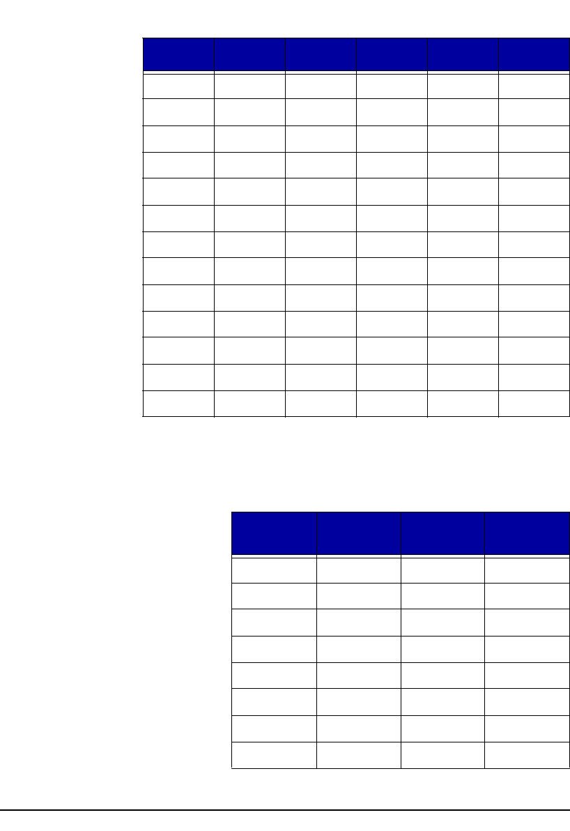
We, Wj, and Wk Frequency Weighting
Freq ( Hz)
Nominal
Freq ( Hz)
True We dB Wj dB Wk dB Tolerance
dB
0.100 0.100 -24.08 -30.18 -30.11 +2 / -
0.125 0.1259 -20.09 -26.20 -26.14 +2 / -
0.160 0.1585 -16.14 -22.27 -22.21 +2 / -
0.200 0.1995 -12.27 -18.42 -18.37 +2 / -
0.250 0.2512 -8.60 -14.79 -14.74 +2 / -2
0.315 0.3162 -5.36 -11.60 -11.55 +2 / -2
0.400 0.3981 -2.86 -9.15 -9.11 +1 / -1
0.500 0.5012 -1.27 -7.58 -7.56 +1 / -1
0.630 0.6310 -0.55 -6.77 -6.77 +1 / -1
0.800 0.7943 -0.52 -6.42 -6.44 +1 / -1
1.00 1.00 -1.11 -6.30 -6.33 +1 / -1
1.25 1.259 -2.29 -6.28 -6.29 +1 / -1
1.60 1.585 -3.91 -6.32 -6.13 +1 / -1
2.00 1.995 -5.80 -6.34 -5.50 +1 / -1
2.50 2.512 -7.81 -6.22 -3.97 +1 / -1
3.15 3.162 -9.85 -5.60 -1.86 +1 / -1
4.00 3.981 -11.89 -4.08 -0.31 +1 / -1
5.00 5.012 -13.93 -1.99 +0.33 +1 / -1
6.30 6.310 -15.95 -0.47 +0.46 +1 / -1
8.00 7.943 -17.97 +0.14 +0.32 0
10.0 10.0 -19.98 +0.26 -0.10 +1 / -1
12.5 12.59 -21.99 +0.22 -0.93 +1 / -1
16.0 15.85 -23.99 +0.16 -2.22 +1 / -1
20.0 19.95 -26.00 +0.10 -3.91 +1 / -1
A-14 Frequency Weighting Curves HVM200 Manual
Wg Frequency Weighting (Defined in BS6841:1987)
25.0 25.12 -28.01 +0.06 -5.84 +1 / -1
31.5 31.62 -30.04 +0.00 -7.89 +1 / -1
40.0 39.81 -32.11 -0.08 -10.01 +1 / -1
50.0 50.12 -34.26 -0.25 -12.21 +1 / -1
63.0 63.10 -36.64 -0.63 -14.62 +1 / -1
80.0 79.43 -39.46 -1.45 -17.47 +1 / -1
100 100.0 -43.01 -3.01 -21.04 +1 / -1
125 125.9 -47.46 -5.45 -25.50 +2 / -2
160 158.5 -52.64 -8.64 -30.69 +2 / -2
200 199.5 -58.27 -12.26 -36.32 +2 / -
250 251.2 -64.11 -16.11 -42.16 +2 / -
315 316.2 -70.04 -20.04 -48.10 +2 / -
400 398.1 -76.02 -24.02 -54.08 +2 / -
Freq ( Hz)
Nominal
Freq ( Hz)
True
Wg dB Tolerance
dB
1.00 1.00 -7.5 +1 / -1
1.25 1.26 -6.0 +1 / -1
1.60 1.59 -4.6 +1 / -1
2.00 2.00 -3.4 +1 / -1
2.50 2.51 -2.2 +1 / -1
3.15 3.16 -0.9 +1 / -1
4.00 3.98 -0.0 +1 / -1
5.00 5.01 +0.4 +1 / -1
Freq ( Hz)
Nominal
Freq ( Hz)
True We dB Wj dB Wk dB Tolerance
dB

HVM200 Manual Frequency Weighting Curves A-15
6.30 6.31 +0.1 +1 / -1
8.00 7.94 -1.0 0
10.0 10.00 -2.5 +1 / -1
12.5 12.59 -4.2 +1 / -1
16.0 15.85 -6.3 +1 / -1
20.0 19.95 -8.2 +1 / -1
25.0 25.12 -10.1 +1 / -1
31.5 31.62 -12.1 +1 / -1
40.0 39.81 -14.2 +1 / -1
50.0 50.12 -16.3 +1 / -1
63.0 63.10 -18.7 +1 / -1
80.0 79.43 -21.6 +1 / -1
Freq ( Hz)
Nominal
Freq ( Hz)
True
Wg dB Tolerance
dB

A-16 Frequency Weighting Curves HVM200 Manual
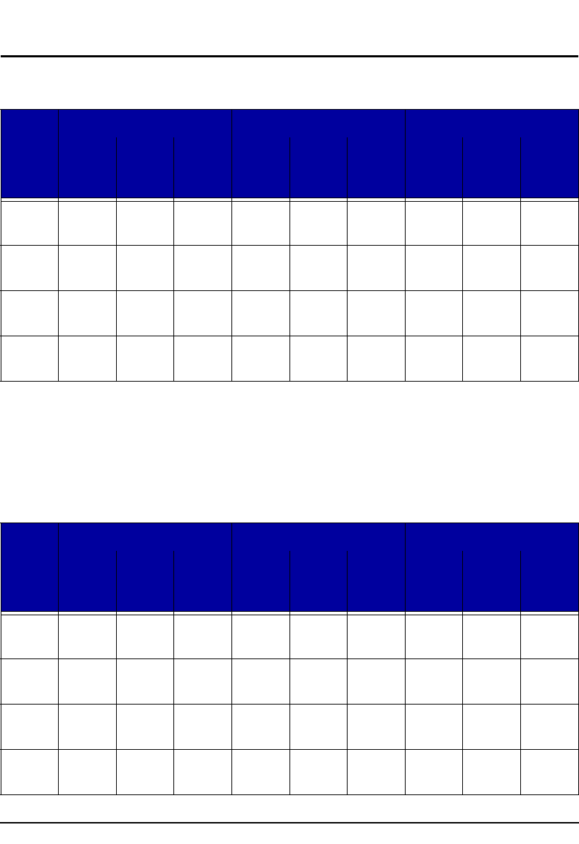
Wm (Whole Body) Frequency Weighting
Freq ( Hz)
Nominal
Freq ( Hz)
True
WM dB Tolerance
dB
0.100 0.100 -36.00 +2 / -
0.125 0.1259 -32.00 +2 / -
0.160 0.1585 -28.01 +2 / -
0.200 0.1995 -24.02 +2 / -
0.250 0.2512 -20.05 +2 / -
0.315 0.3162 -16.12 +2 / -
0.400 0.3981 -12.29 +2 / -
0.500 0.5012 -8.67 +2 / -2
0.630 0.6310 -5.51 +2 / -2
0.800 0.7943 -3.09 +2 / -2
1.00 1.00 -1.59 +2 / -2
1.25 1.259 -0.85 +1 / -1
1.60 1.585 -0.59 +1 / -1
2.00 1.995 -0.61 +1 / -1
2.50 2.512 -0.82 +1 / -1
3.15 3.162 -1.19 +1 / -1
4.00 3.981 -1.74 +1 / -1
5.00 5.012 -2.50 +1 / -1
6.30 6.310 -3.49 +1 / -1
8.00 7.943 -4.70 0
10.0 10.0 -6.12 +1 / -1
12.5 12.59 -7.71 +1 / -1
16.0 15.85 -9.44 +1 / -1
20.0 19.95 -11.25 +1 / -1
25.0 25.12 -13.14 +1 / -1

HVM200 Manual Frequency Weighting Curves A-17
31.5 31.62 -15.09 +1 / -1
40.0 39.81 -17.10 +1 / -1
50.0 50.12 -19.23 +1 / -1
63.0 63.10 -21.58 +1 / -1
80.0 79.43 -24.38 +2 / -2
100 100.0 -27.93 +2 / -2
125 125.9 -32.37 +2 / -2
160 158.5 -37.55 +2 / -2
200 199.5 -43.18 +2 / -
250 251.2 -49.02 +2 / -
315 316.2 -54.95 +2 / -
400 398.1 -60.92 +2 / -
500 501.2 -66.91 +2 / -
630 631.0 -72.91 +2 / -
800 794.3 -78.91 +2 / -
Freq ( Hz)
Nominal
Freq ( Hz)
True
WM dB Tolerance
dB
A-18 Frequency Weighting Curves HVM200 Manual
Typical Measurements Ranges
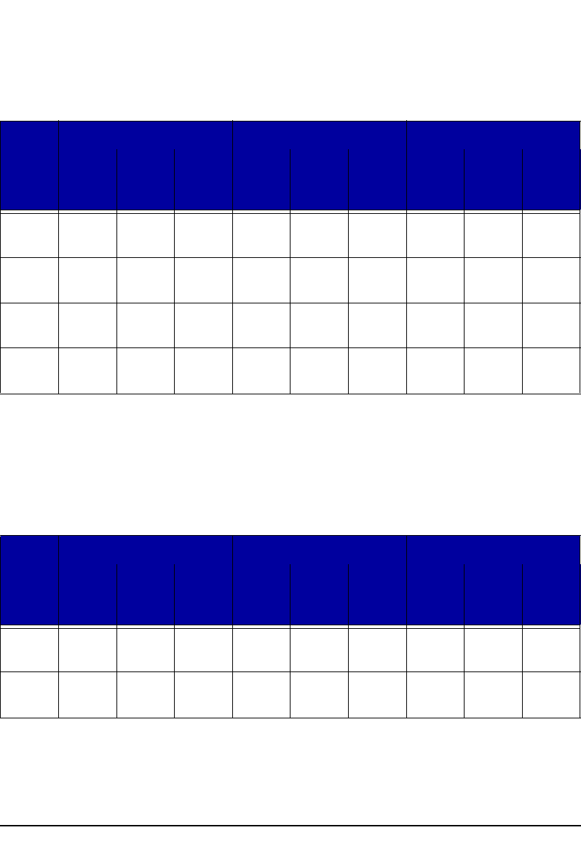
Vibration - Fa
Notes:
1. Under-Range (?) - The noise floor is below the measurement range of the analog to digital
converter.
2. The data in the above table was obtained by electrically testing the HVM200.
Vibration - Fb, Fc, and Wf
Direct Charge (1000pF) ICP®
Gain Noise
Floor
dBµV
RMS
Range
dBµV
Peak
Range
dBµV
Noise
Floor
dBµV
RMS
Range
dBµV
Peak
Range
dBµV
Noise
Floor
dBµV
RMS
Range
dBµV
Peak
Range
dBµV
0 dB See
Note 1
60 dB
74-134
38 dB
99-137
See
Note 1
60 dB
74-134
38 dB
99-137
See
Note 1
60 dB
74-134
38 dB
99-137
20 dB See
Note 1
60 dB
54-114
38 dB
79-117
See
Note 1
60 dB
54-114
38 dB
79-117
See
Note 1
60 dB
54-114
38 dB
79-17
40 dB 26 58 dB
36-94
36 dB
61-97
26 58 dB
36-94
36 dB
61-97
26 58 dB
36-94
36 dB
61-97
60 dB 17 47 dB
27-74
25 dB
52-77
17 47 dB
27-74
25 dB
52-77
23 41 dB
33-74
19 dB
58-77
Direct Charge (1000pF) ICP®
Gain Noise
Floor
dBµV
RMS
Range
dBµV
Peak
Range
dBµV
Noise
Floor
dBµV
RMS
Range
dBµV
Peak
Range
dBµV
Noise
Floor
dBµV
RMS
Range
dBµV
Peak
Range
dBµV
0 dB 64 60 dB
74-134
38 dB
99-137
64 60 dB
74-134
38 dB
99-137
64 60 dB
74-134
38 dB
99-137
20 dB 44 60 dB
54-114
38 dB
79-117
44 60 dB
54-114
38 dB
79-117
44 60 dB
54-114
38 dB
79-117
40 dB 30 54 dB
40-94
32 dB
65-97
30 54 dB
40-94
32 dB
65-97
30 54 dB
40-94
32 dB
65-97
60 dB 23 41 dB
33-74
19 dB
58-77
23 41 dB
33-74
19 dB
58-77
23 41 dB
33-74
19 dB
58-77
HVM200 Manual Frequency Weighting Curves A-19
Notes
1. The data in the above table was obtained by electrically testing the HVM200.
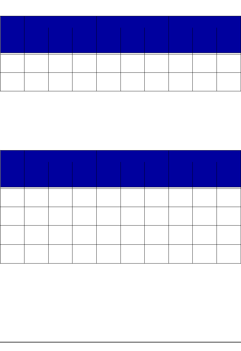
Hand Arm - Wh
Notes:
1. Under-Range (?) - The noise floor is below the measurement range of the analog to digital
converter.
2. The data in the above table was obtained by electrically testing the HVM200.
Whole Body - Wm
Direct Charge (1000pF) ICP®
Gain Noise
Floor
dBµV
RMS
Range
dBµV
Peak
Range
dBµV
Noise
Floor
dBµV
RMS
Range
dBµV
Peak
Range
dBµV
Noise
Floor
dBµV
RMS
Range
dBµV
Peak
Range
dBµV
0 dB See
Note 1
60 dB
74-134
38 dB
99-137
See
Note 1
60 dB
74-134
38 dB
99-137
See
Note 1
60 dB
74-134
38 dB
99-137
20 dB See
Note 1
60 dB
54-114
38 dB
79-117
See
Note 1
60 dB
54-114
38 dB
79-117
See
Note 1
60 dB
54-114
38 dB
79-117
40 dB See
Note 1
60 dB
34-94
38 dB
59-97
See
Note 1
60 dB
34-94
38 dB
59-97
See
Note 1
60 dB
34-94
38 dB
59-97
60 dB 10 54 dB
20-74
32 dB
45-77
10 54 dB
20-74
32 dB
45-77
10 54 dB
20-74
32 dB
45-77
Direct Charge (1000pF) ICP®
Gain Noise
Floor
dBµV
RMS
Range
dBµV
Peak
Range
dBµV
Noise
Floor
dBµV
RMS
Range
dBµV
Peak
Range
dBµV
Noise
Floor
dBµV
RMS
Range
dBµV
Peak
Range
dBµV
0 dB See
Note 1
60 dB
74-134
38 dB
99-137
See
Note 1
60 dB
74-134
38 dB
99-137
See
Note 1
60 dB
74-134
38 dB
99-137
20 dB See
Note 1
60 dB
54-114
38 dB
79-117
See
Note 1
60 dB
54-114
38 dB
79-117
See
Note 1
60 dB
54-114
38 dB
79-117
A-20 Frequency Weighting Curves HVM200 Manual
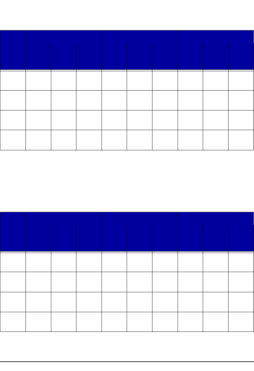
Notes:
1. Under-Range (?) - The noise floor is below the measurement range of the analog to digital
converter.
2. The data in the above table was obtained by electrically testing the HVM200.
Whole Body - Wc
Notes:
1. Under-Range (?) - The noise floor is below the measurement range of the analog to digital
converter.
2. The data in the above table was obtained by electrically testing the HVM200.
40 dB See
Note 1
60 dB
34-94
38 dB
59-97
See
Note 1
60 dB
34-94
38 dB
59-97
See
Note 1
60 dB
34-94
38 dB
59-97
60 dB 14 50 dB
24-74
28 dB
49-77
14 50 dB
24-74
28 dB
49-77
14 50 dB
24-74
28 dB
49-77
Direct Charge (1000pF) ICP®
Gain Noise
Floor
dBµV
RMS
Range
dBµV
Peak
Range
dBµV
Noise
Floor
dBµV
RMS
Range
dBµV
Peak
Range
dBµV
Noise
Floor
dBµV
RMS
Range
dBµV
Peak
Range
dBµV
0 dB See
Note 1
60 dB
74-134
38 dB
99-137
See
Note 1
60 dB
74-134
38 dB
99-137
See
Note 1
60 dB
74-134
38 dB
99-137
20 dB See
Note 1
60 dB
54-114
38 dB
79-117
See
Note 1
60 dB
54-114
38 dB
79-117
See
Note 1
60 dB
54-114
38 dB
79-117
40 dB See
Note 1
60 dB
34-94
38 dB
59-97
See
Note 1
60 dB
34-94
38 dB
59-97
See
Note 1
60 dB
34-94
38 dB
59-97
60 dB 13 51 dB
23-74
29 dB
48-77
13 51 dB
23-74
29 dB
48-77
23 41 dB
33-74
19 dB
58-77
Direct Charge (1000pF) ICP®
Gain Noise
Floor
dBµV
RMS
Range
dBµV
Peak
Range
dBµV
Noise
Floor
dBµV
RMS
Range
dBµV
Peak
Range
dBµV
Noise
Floor
dBµV
RMS
Range
dBµV
Peak
Range
dBµV
HVM200 Manual Frequency Weighting Curves A-21
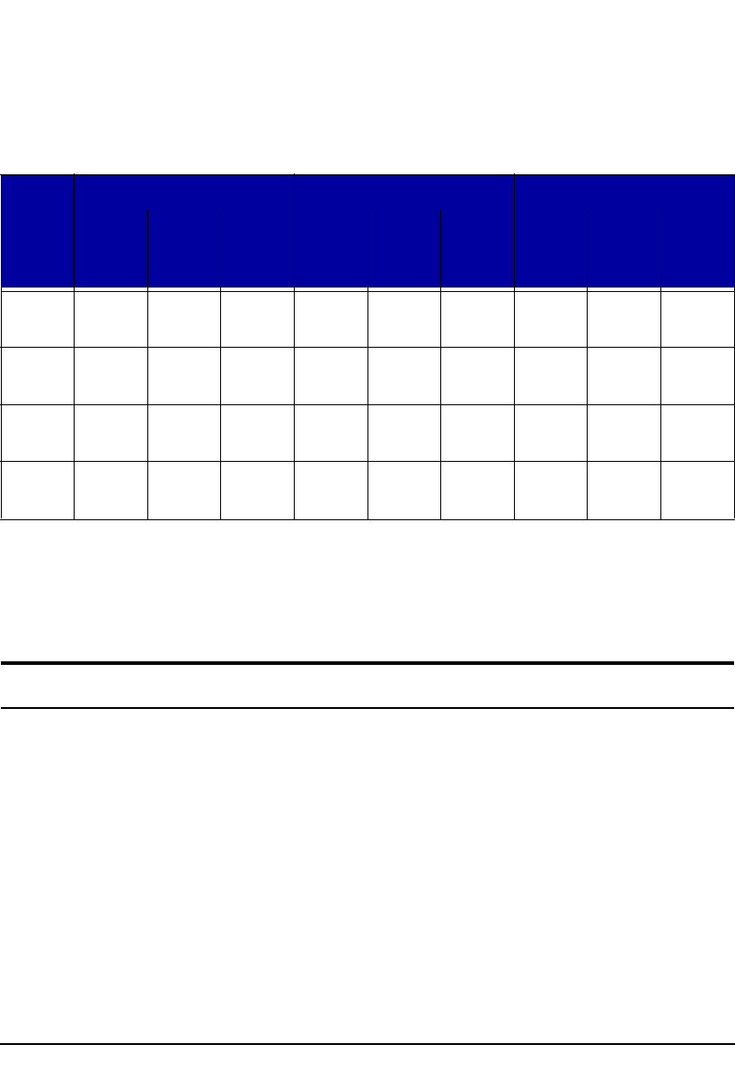
Whole Body - Wd, We
Notes:
1. Under-Range (?) - The noise floor is below the measurement range of the analog to digital
converter.
2. The data in the above table was obtained by electrically testing the HVM200.
Whole Body - Wg
Notes:
Direct Charge (1000pF) ICP®
Gain Noise
Floor
dBµV
RMS
Range
dBµV
Peak
Range
dBµV
Noise
Floor
dBµV
RMS
Range
dBµV
Peak
Range
dBµV
Noise
Floor
dBµV
RMS
Range
dBµV
Peak
Range
dBµV
0 dB See
Note 1
60 dB
74-134
38 dB
99-137
See
Note 1
60 dB
74-134
38 dB
99-137
See
Note 1
60 dB
74-134
38 dB
99-137
20 dB See
Note 1
60 dB
54-114
38 dB
79-117
See
Note 1
60 dB
54-114
38 dB
79-117
See
Note 1
60 dB
54-114
38 dB
79-117
40 dB See
Note 1
60 dB
34-94
38 dB
59-97
See
Note 1
60 dB
34-94
38 dB
59-97
See
Note 1
60 dB
34-94
38 dB
59-97
60 dB 11 53 dB
21-74
31 dB
46-77
11 53 dB
21-74
31 dB
46-77
23 41 dB
33-74
19 dB
58-77
Direct Charge (1000pF) ICP®
Gain Noise
Floor
dBµV
RMS
Range
dBµV
Peak
Range
dBµV
Noise
Floor
dBµV
RMS
Range
dBµV
Peak
Range
dBµV
Noise
Floor
dBµV
RMS
Range
dBµV
Peak
Range
dBµV
0 dB See
Note 1
60 dB
74-134
38 dB
99-137
See
Note 1
60 dB
74-134
38 dB
99-137
See
Note 1
60 dB
74-134
38 dB
99-137
20 dB See
Note 1
60 dB
54-114
38 dB
79-117
See
Note 1
60 dB
54-114
38 dB
79-117
See
Note 1
60 dB
54-114
38 dB
79-117
40 dB 24 60 dB
34-94
38 dB
59-97
24 60 dB
34-94
38 dB
59-97
24 60 dB
34-94
38 dB
59-97
60 dB 14 50 dB
24-74
28 dB
49-77
14 50 dB
24-74
28 dB
49-77
14 50 dB
24-74
28 dB
49-77
A-22 Standards Met HVM200 Manual
1. Under-Range (?) - The noise floor is below the measurement range of the analog to digital
converter.
2. The data in the above table was obtained by electrically testing the HVM200.
Whole Body - Wm, Wj, Wk
Notes:
1. Under-Range (?) - The noise floor is below the measurement range of the analog to digital
converter.
2. The data in the above table was obtained by electrically testing the HVM200.
Standards Met
Type Precision
The Larson Davis HVM200 Human Vibration Meter is a Type 1 instrument designed for use in
assessing vibration as perceived by human beings. The instrument meets the requirements of ISO
8041:2005(E).HVM200
Additionally, the current ISO 8041:2005 standard, and therefore the HVM200 is compatible with the
standards listed below. These standards define methods for the measurement of whole-body and hand-
arm vibration.
• ISO 2631-1:1997 Mechanical vibration and shock -- Evaluation of human exposure to whole-
body vibration -- Part 1: General requirements
• ISO 2631-2:2003 Evaluation of human exposure to whole-body vibration -- Part 2: Continuous
and shock-induced vibrations in buildings (1 to 80 Hz)
Direct Charge (1000pF) ICP®
Gain Noise
Floor
dBµV
RMS
Range
dBµV
Peak
Range
dBµV
Noise
Floor
dBµV
RMS
Range
dBµV
Peak
Range
dBµV
Noise
Floor
dBµV
RMS
Range
dBµV
Peak
Range
dBµV
0 dB See
Note 1
60 dB
74-134
38 dB
99-137
See
Note 1
60 dB
74-134
38 dB
99-137
See
Note 1
60 dB
74-134
38 dB
99-137
20 dB See
Note 1
60 dB
54-114
38 dB
79-117
See
Note 1
60 dB
54-114
38 dB
79-117
See
Note 1
60 dB
54-114
38 dB
79-117
40 dB 24 60 dB
34-94
38 dB
59-97
24 60 dB
34-94
38 dB
59-97
24 60 dB
34-94
38 dB
59-97
60 dB 13 51 dB
23-74
29 dB
48-77
13 51 dB
23-74
29 dB
48-77
18 46 dB
28-74
24 dB
53-77

HVM200 Manual Standards Met A-23
• ISO 2631-4:2001 Mechanical vibration and shock -- Evaluation of human exposure to whole-
body vibration -- Part 4: Guidelines for the evaluation of the effects of vibration and rotational
motion on passenger and crew comfort in fixed-guideway transport systems
• ISO 5349-1:2001 Mechanical vibration -- Measurement and evaluation of human exposure to
hand-transmitted vibration -- Part 1: General requirements
• ISO 5349-2:2001 Mechanical vibration -- Measurement and evaluation of human exposure to
hand-transmitted vibration -- Part 2: Practical guidance for measurement at the workplace
Declaration of Conformity
PCB Piezotroncs Inc. declares that:
• Product Name: Human Vibration Meter
• Model: HVM200
The Model HVM200 Human Vibration Meter complies with the European Community EMC
Directive (2004/108/EC) and also with the Low Voltage Safety Directive (2006/95/EC) by meeting
the following standards:
• IEC 61326-1:2005-Electrical equipment for measurement, control and laboratory use-EMC
requirements-Part 1: General requirements.
•IEC 61000-4-2:2008-Electrostatic discharge immunity test ±4kV contact ESD and ±8kV air
ESD). Performance Criteria B.
•IEC61000-4-3:2006 with am1 2007-Radiated, radio-frequency electromagnetic field immunity
test. 26 to 1,000 MHz at 10 V/m, 1.4 to 2.0 GHz at 3 V/M, and 2.0 to 2.7 GHz at 1 V/M, all with
AM 80%, 1 kHz. ±6% from 1 g. Performance Criteria A.
•IEC61000-4-8:2009: Power frequency magnetic field immunity test. 80 A/m, 50/60 Hz. 3%
from 1 g. Performance Criteria A.
•CISPR 11:2009-Industrial, scientific and medical equipment-Radio-frequency disturbance char-
acteristics-Limits and methods of measurement. Class B, Group 1.
• IEC 61010-1:2001- Safety requirements for electrical equipment for measurement, control, and
laboratory use-Part 1:General requirements.

A-24 Standards Met HVM200 Manual
HVM200 Manual Glossary B-1
APPENDIX
BGlossary
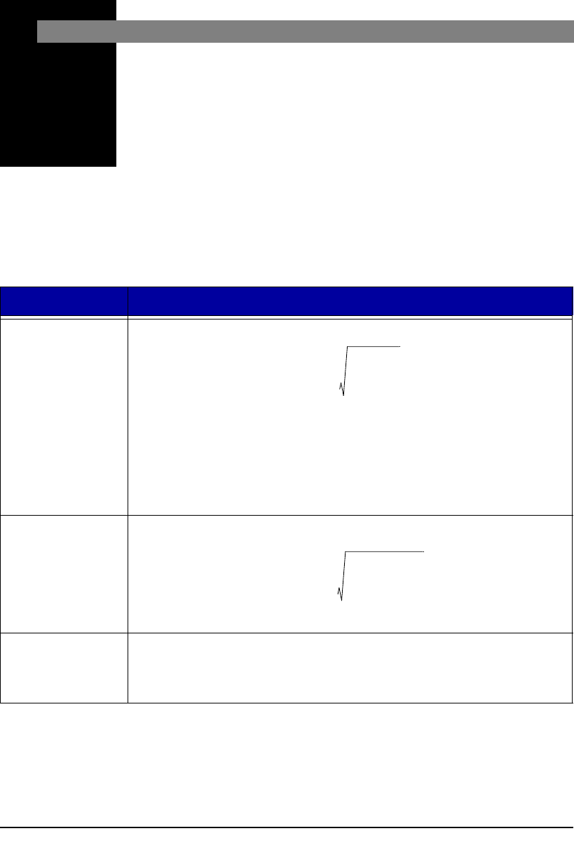
The following table contains definitions and calculations for
terminology used in the HVM200 manual.
Term Equation Description
RMS
Acceleration
T= Integration time in seconds.
aw (t) = instantaneous acceleration.
t = Time, in seconds.
The Aeq integration time is from Run to Reset; the display is updated once
per second.
RMS
Acceleration in
Decibels
ao = reference acceleration, 10-6 m/s2 or 10-5 m/s2 (user selectable)
Allowed
Exposure Time
Aeq 1
T
---aw
2ttd
0
T
=
Aeq 20Log 1
T
---aw
2t
ao
2
-------------td Bd
0
T
=
2.8ms
2
Aeq
28hours
B-2 HVM200 Manual
Energy
Equivalent RMS
Acceleration
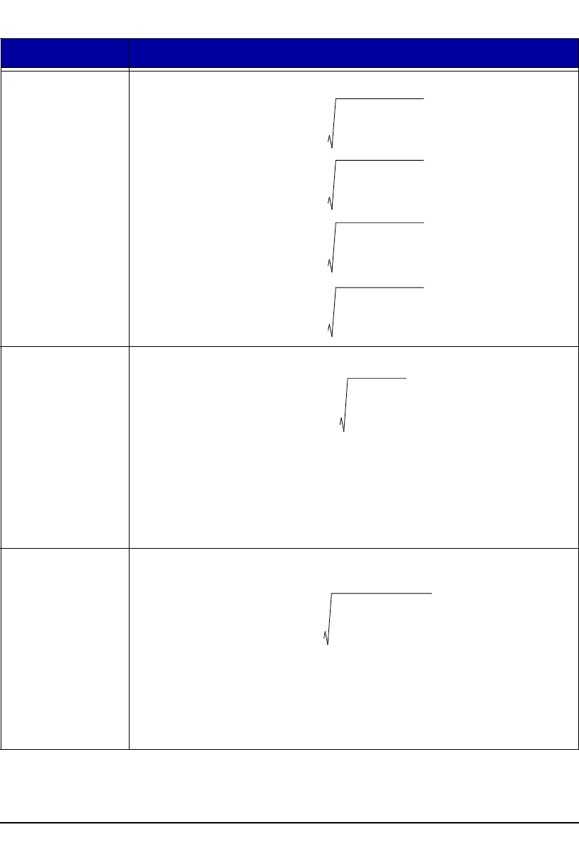
The HVM100 measures the following quantities:
Running RMS
Acceleration
LINEAR
Integration time, in seconds.
to = Observation time
The linear Arms integration time is controlled by the Averaging time setting;
a new linear Arms value is calculated and displayed at the end of each inte-
gration period.
Running RMS
Acceleration
EXPONENTIAL
Time constant of the measurement.
An averaging time of SLOW is equivalent to a time constant of 1 second.
Term Equation Description
A8 1
8Hours
------------------- aw
2ttd
0
T
=
A4 1
4Hours
------------------- aw
2ttd
0
T
=
A2 1
2Hours
------------------- aw
2ttd
0
T
=
A1 1
1Hours
------------------- aw
2ttd
0
T
=
Arms 1
---aw
2ttd
t0
t0
=
-
Arms 1
---aw
2t tt
0
------
exp td
t0
=
-
-

HVM200 Manual B-3
Vibration Dose
Value
The VDV integration time is from Run to Reset; the display is updated once
per second. The VDV is not calculated for units of dB or g.
Maximum
Transient
Vibration Value
Amax = maximum reading of all Arms readings from Run to Reset.
The display is updated at the end of each Averaging time period.
Minimum
Transient
Vibration Value
Amin = minimum reading of all Arms readings from Run to Reset.
The display is updated at the end of each Averaging time period.
Long Term
Maximum Peak Amp = peak level of the instantaneous weighted acceleration, aw(t); mea-
sured over the entire measurement period, from Run to Reset.
The displayed Amp value is updated once per second.
Short Term
Maximum Peak Peak = peak level of the instantaneous weighted acceleration, aw(t); mea-
sured during one Averaging time period.
The peak measurement period is controlled by the Averaging time setting; a
new Peak value is calculated and displayed at the end of each Averaging
time period.
Long Term Crest
Factor
The CFmp measurement period is from Run to Reset; the display is updated
once per second.
Term Equation Description
VDV aw
4ttd
0
T
1
4
---
=
CFmp Amp
Aeq
-----------=

B-4 HVM200 Manual
Short Term
Crest Factor
The CF measurement period is controlled by the Averaging time setting; a
new CF value is calculated and displayed at the end of each Averaging time
period. CF is not calculated if the Averaging time setting is SLOW.
Summed
Instantaneous
Acceleration
aw(t) = instantaneous, summed acceleration
awx(t), awy(t), awz(t) = X, Y, and Z axis instantaneous acceleration
Kx,Ky,Kz = X, Y, and Z axis Sum Factors
The HVM200 uses the formula above to calculate the instantaneous,
summed acceleration, aw(t). This value is then used to calculate a sum
quantity for the Arms,Amin, Amax, Amp, Aeq, Peak, VDV, and PE. K factors
affect only sum value and not individual axis data.
Term Equation Description
CF Peak
Arms
-------------=
Kxawx t 2Kyawy t 2
+Kzawz t 2
+

HVM200 Manual Regulatory Compliance Statement A-1
APPENDIX
ARegulatory Compliance
Statement
FCC
This device complies with part 15 of the FCC rules. Operation is subject to the following two
conditions: (1) This device may not cause harmful interference, and (2) this device must accept any
interference received, including interference that may cause undesired operation. Any changes or
modifications not expressly approved by manufacturer could void the user’s authority to operate the
equipment.
IMPORTANT! Any changes or modifications not expressly approved by the party responsible for
compliance could void the user’s authority to operate this equipment.
Industry Canada
This device complies with Industry Canada licence-exempt RSS standard(s). Operation is subject to
the following two conditions: (1) this device may not cause interference, and (2) this device must
accept any interference, including interference that may cause undesired operation of the device.
This Class [*] digital apparatus complies with Canadian ICES-003.
Cet appareil numérique de la classe [*] est conforme à la norme NMB-003 du Canada
Le présent appareil est conforme aux CNR d’Industrie Canada applicables aux appareils radio
exempts de licence. L’exploitation est autorisée aux deux conditions suivantes: (1) l’appareil ne doit
pas produire de brouillage, et (2) l’utilisateur de l’appareil doit accepter tout brouillage radioélectrique
subi, meme si le brouillage est susceptible d’en compromettre le fonctionnement.
IMPORTANT! Tous les changements ou modifications pas expressément approuvés par la partie
responsable de la conformité ont pu vider l’autorité de l’utilisateur pour actioner cet équipment.
47 CFR 15.505- FCC
Class B
NOTE: This equipment has been tested and found to comply with the limits for a Class B digital
device, pursuant to part 15 of the FCC Rules. These limits are designed to provide reasonable
protection against harmful interference in a residential installation. This equipment generates, uses and

A-2 Class A- FCC HVM200 Manual
can radiate radio frequency energy and, if not installed and used in accordance with the instructions,
may cause harmful interference to radio communications. However, there is no guarantee that
interference will not occur in a particular installation. If this equipment does cause harmful
interference to radio or television reception, which can be determined by turning the equipment off
and on, the user is encouraged to try to correct the interference by one or more of the following
measures:
• Reorient or relocate the receiving antenna.
• Increase the separation between the equipment and receiver.
• Connect the equipment into an outlet on a circuit different from that to which the receiver
• is connected.
• Consult the dealer or an experienced radio/ TV technician for help.
Class A- FCC
NOTE: This equipment has been tested and found to comply with the limits for a Class A digital
device, pursuant to part 15 of the FCC Rules. These limits are designed to provide reasonable
protection against harmful interference when the equipment is operated in a commercial environment.
This equipment generates, uses, and can radiate radio frequency energy and, if not installed and used
in accordance with the instruction manual, may cause harmful interference to radio communications.
Operation of this equipment in a residential area is likely to cause harmful interference in which case
the user will be required to correct the interference at his own expense.