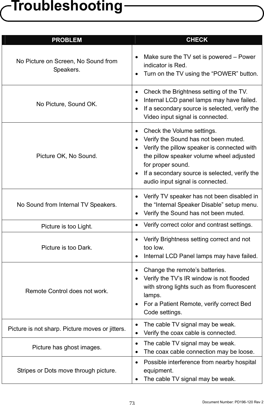
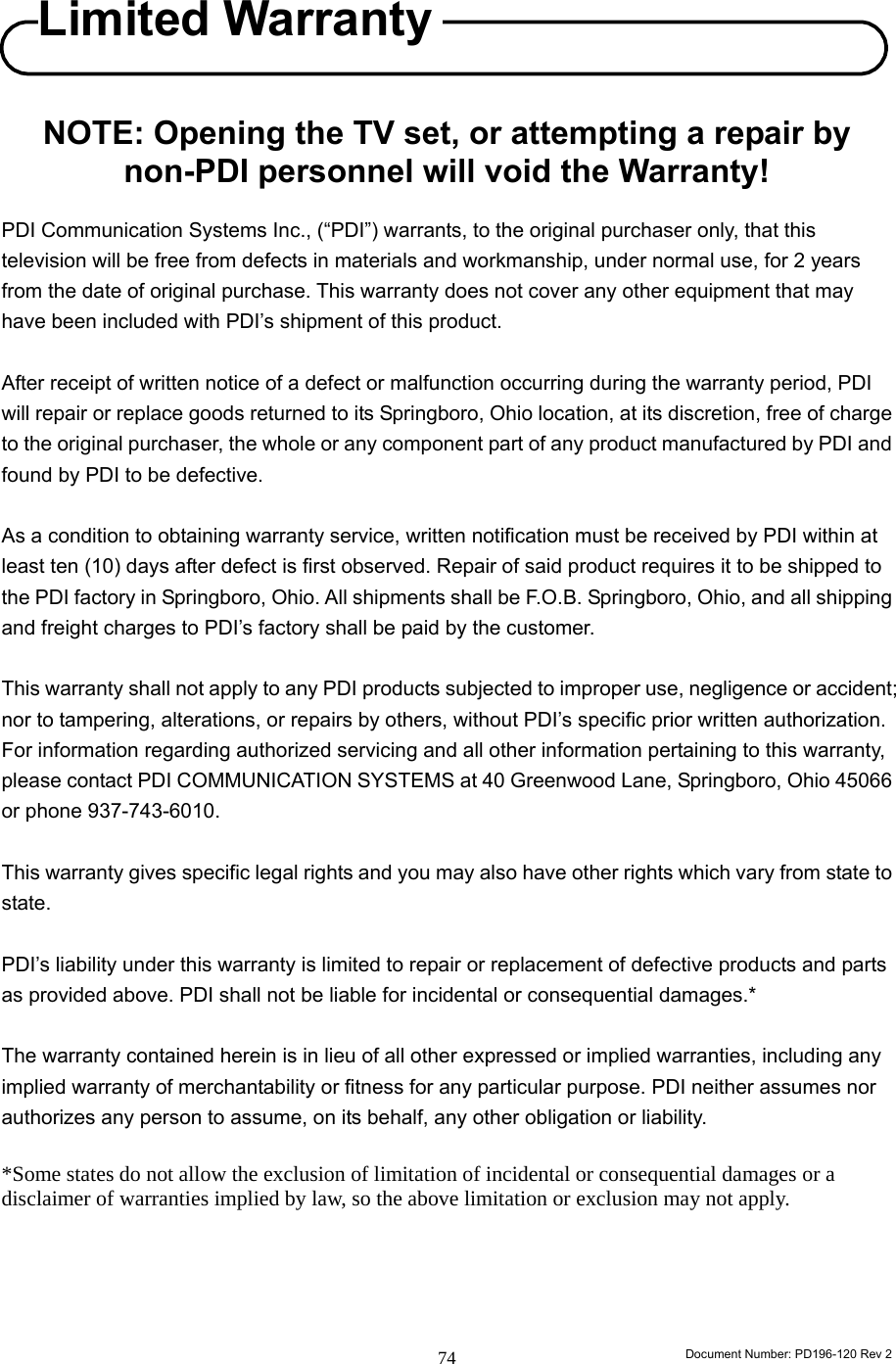
PDI Communication System P19LCDC Healthcare TV User Manual
PDI Communication System, Inc. Healthcare TV
UserManual.wiki
>
PDI Communication System
>
P19LCDC User Manual
User manual
Navigation menu
Upload a User Manual
Namespaces
Wiki Guide
HTML
PDF
Info
Views
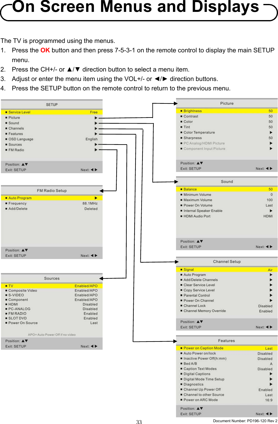
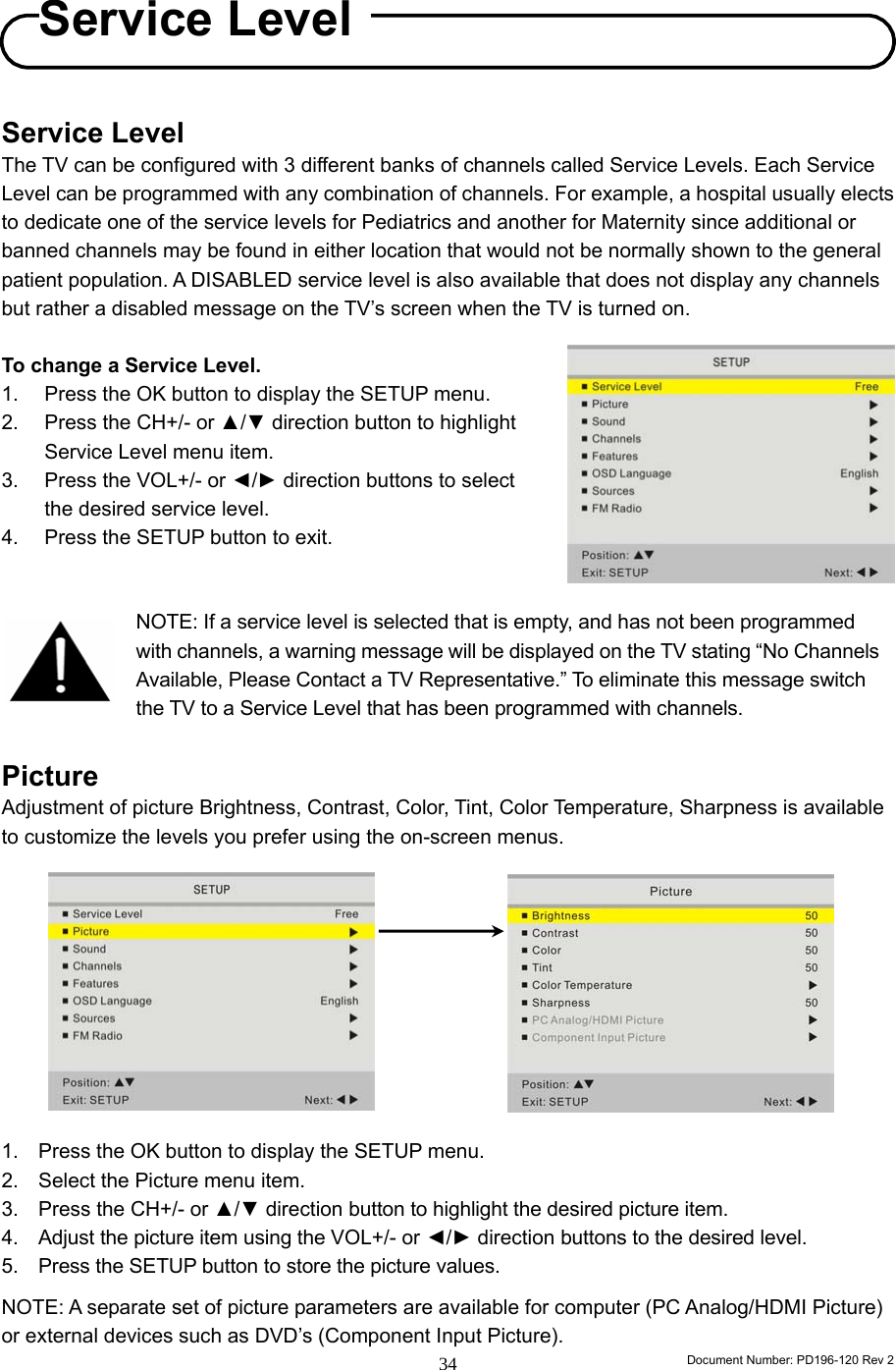
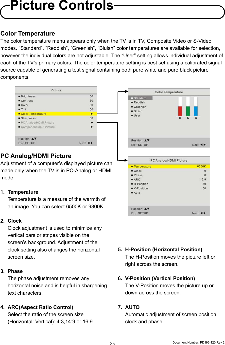
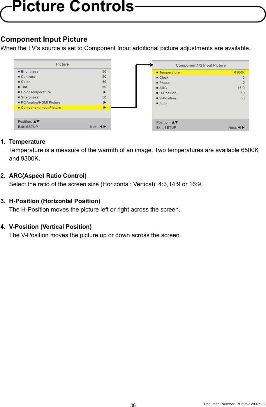
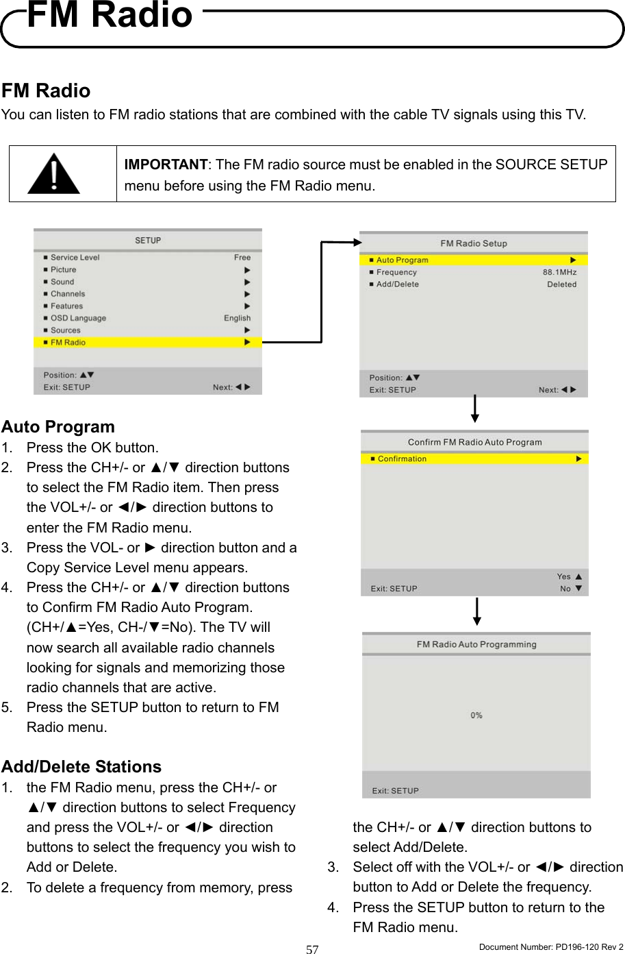
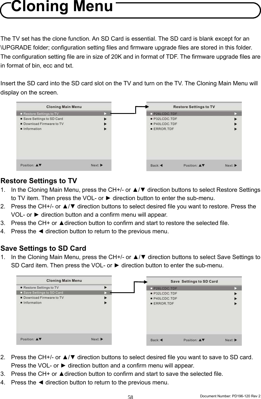
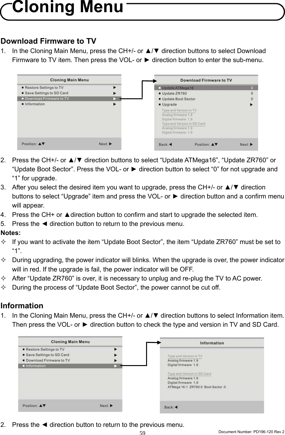
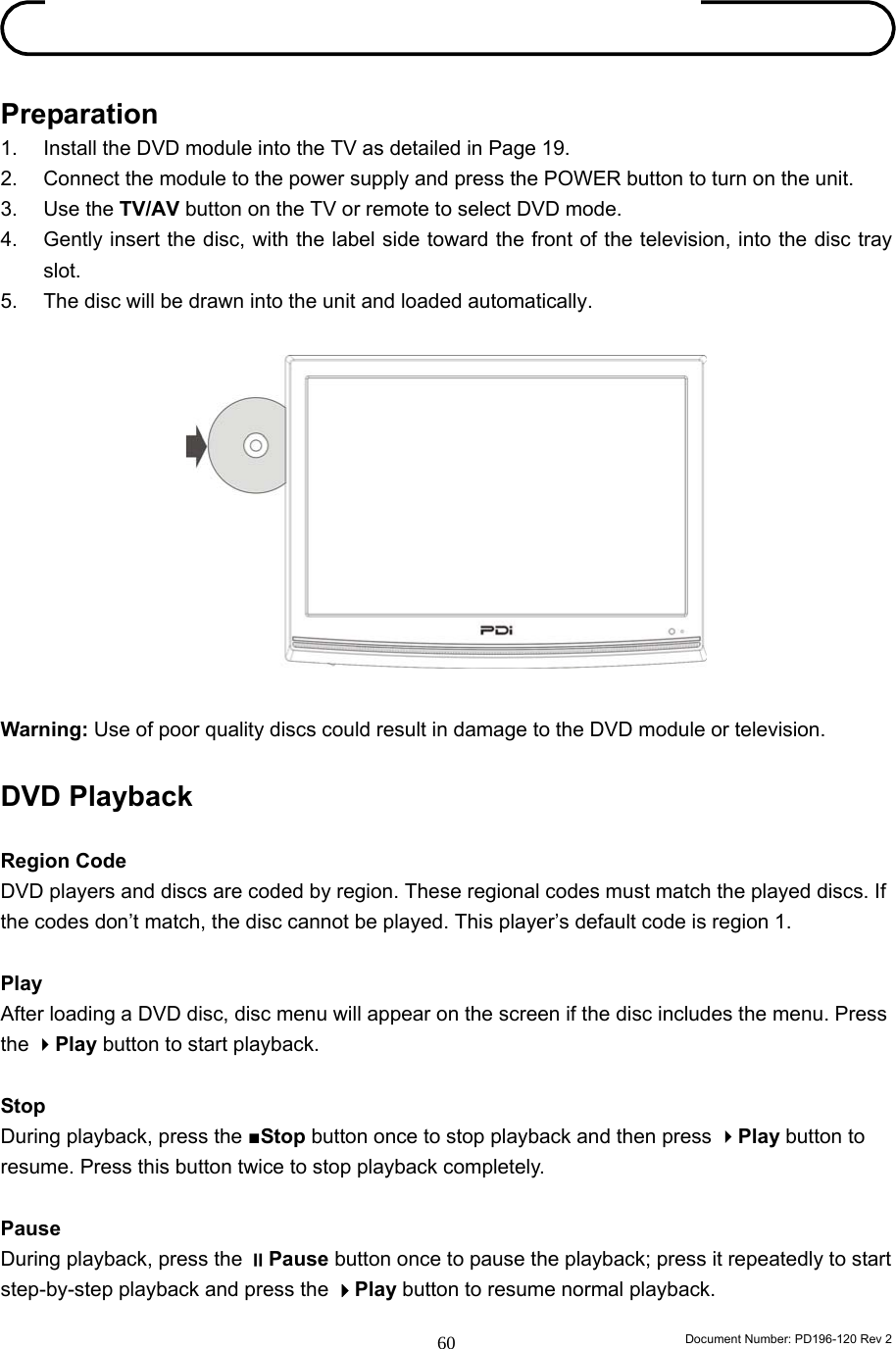
User Manual
Discussion / Help
Navigation