PEERLESS Boiler Manual L0308189
User Manual: PEERLESS PEERLESS Boiler Manual PEERLESS Boiler Owner's Manual, PEERLESS Boiler installation guides
Open the PDF directly: View PDF ![]() .
.
Page Count: 45
MI/MIH
Boilers
Installation,
Operation
Maintenance
Manual
Pr=-EI_LESS _
CAST IRON BOILERS

MI Model Available for Natural or LP Gas
•Standit_g Pilot (3 9 sectior_) with 8(7_ AFUE
•[-Ioneywell SmartValve ®Intermittent Ignition (3-9 section)
with 82% AFUE
MIH Mid-E._f_ency Model Available in 3-6 Sections
for Natural Gas
• Honeywell SmartValve ®Intermittent Ignition with 83% AFUE
•Qualifies for Utility Company Energy Rebates in Some Areas
Natural Draft (Chimney) Venting
Low Profile Design
•Internal Horizontal to Vertical Draft Diverter
•Ideal for Ir_stallations with Low Ceilings
Steel Push Nipples
• Provici( _ a Permar_ent _Vct_'r 7"(c)hl Seed Between Sections
•Unaffected by PetroIcum alzd Oilier Contaminants
Deluxe Insulated Enameled Steel Jacket
•Reduces Boiler Heat Loss
•Completely Encloses Gas Valve and Burners
Safety Controls
•Vent Safety ShutoffSwitch
•Flame Rollout Safety ShutoffSwitch •Standing Pilot or Honeywell SmartValve _
Intermittent Ignition
•Honeywell Operating Controls
• Taco Circulator
• Elec. Operated Automatic Vent Damper
•Grundfos Circulator
• 50 PSI Safety Relief Valve
•Non-Combustible Floor Pan
c_xStltartVah;_t i._ r_ rt,gislt_rt,d Ircldt,illark o I llo¢letlw(tll Corporcltion.
l_crless q[f_,r on_ of tll_" mosl c:omprelt_.nsive wctrrarlly prof.jrarrus
in tttt_ ind_Lslr_/. All I_ (_rlt'ss r_'sidt't_ticd c_¢_t iro,_ !_oil<.rs inc'!_d_, c_ lidl one tj_!(_r Illarl€_rlltj. A limited. ['_[_[_-r_kl_SS ®
I{]_'limt_ ivtlrranQj Ls p¢'ovlcl_'d.]_?r tlt_' ('(t_%l ilOtl _;('('lioll.% of l)(t('rl_'._;:_ rt'sid_'llti_ll hot Ivat_:r Ix)liters
[)(y(!ll({s._; _IL'_o provld(,s cl IIIIlil('_l. It'll II(!(_lr ttl(lYltllllt] (.ill Ih¢" C(l.'ql IYOtl N(!(?liolls q['il.s I'_Si(Jt_IIli_ll
sI(_(__I_ I)oilt,rs. l'_t _(, tz!I(1 It "_I _1_"(_r _"xt_"r_(1<'(1 tmt_rrczl iIi(".s (atil X ii f_ (11id I_ll)ol ar(_ _to_v(_v(_ lied)& ". CAST IRON BOILERS
/'/(,cLs(_ co¢l._tdt ['(,('rli,ss [ ](,_ll(,_ (2)m[J(lll{/ ]OF Coltll)l(.lt, it)(iFK(llll!j it!]orlnaliorL
Peerless Heater Company * 231 North Walnut Street * Boyertown. PA 19512 1021 * 610 367 2153 * www,peerless-heater.eom
FAB MI l_l {3/02 5M)
Pnnled _n U S A
USING THIS MANUAL 1
A. INSTALLATION SEQUENCE ............. 1
B. SPECIAL ATTENTION BOXES ........... 1
1. PREINSTALLATION 2
A. ACCESSIBILITY CLEARANCES .......... 2
B. CLEARANCE FROM COMBUSTIBLE
CONSTRUCTION ..................... 2
C. AIR FOR COMBUSTION AND
VENTILATION ....................... 2
D. LIQUEFIED PETROLEUM (LP) GAS ....... 4
E. INSTALLATION SURVEY ............... 4
E PLANNING THE LAYOUT ............... 4
7. START-UP PROCEDURES 20
A. COMPLETING THE INSTALLATION ...... 20
B. CONTROL DESCRIPTIONS ............. 24
C. ADJUSTMENT OF GAS PRESSURE
REGULATOR ....................... 24
D. ADJUSTMENT OF PILOT GAS FLOW .... 24
E. CHECKING BURNER INPUT ............ 24
E CHECK-OUT PROCEDURE ............. 25
8. TROUBLESHOOTING 26
A. SHUT-DOWN CAUSED BY PILOT OUTAGE,
BLOCKED VENT SHUT-OFF SWITCH OR
FLAME ROLL-OUT SAFETY SHUT-OFF
SWITCH ........................... 26
B. TROUBLESHOOTING GUIDES .......... 26
A. BOILER SUPPLY AND RETURN .......... 6
B. SAFETY RELIEF VALVE ................ 7
C. PIPING FOR ZONED SYSTEMS .......... 8
D. EXPANSION TANK .................... 9
E. INDIRECT-FIRED WATER HEATER ........ 9
E FREEZE PROTECTION ................. 9
A. INTEGRAL DRAFT HOOD ............. !0
B. VENT DAMPER INSTALLATION -
GENERAL .......................... 10
C. VENT PIPING AND CHIMNEY .......... 11
D. BOILER REMOVAL FROM COMMON
VENTING SYSTEM ................... 12
A. GENERAL .......................... 29
B. DAILY (WITH BOILER IN USE) .......... 29
C. WEEKLY (WITH BOILER IN USE) ........ 29
D. MONTHLY (WITH BOILER IN USE) ....... 29
E. ANNUALLY (BEFORE START OF HEATING
SEASON) .......................... 30
10. BOILER DIMENSIONS _ _TINGS 31
A. BASE/COMBUSTIBLE FLOOR PAN ....... 32
B. MANIFOLD/GAS TRAIN ............... 34
C. BLOCK/DRAFT HOOD ................ 36
D. JACKET ........................... 38
E. CONTROLS/CIRCULATOR/VENT
DAMPER .......................... 40
A. WIRING ........................... 15
B. ZONED SYSTEM WIRING ............. 15
C. CONTROLS ........................ 15
D. SEQUENCE OF OPERATION ........... 16
Follow thetnsta[lattoninstructionspro',,'_ded ill this
manual m the order shown The order ot these
mstructLons has been set m order to provide the installer
with a logical sequence ol steps that wdl mulmllze
potenhal interferences and maximize safety, during
boiler mstallatLon
Indicates a condition or hazard which will cause
severe personal injury, death or major property
damage.
Throughout thLs manual you will see speoal attenuon
boxes intended to supplement the mstmct=ons and make
speoal nohce of potenhal hazards These categories
mean m the judgment of Peerless Heater Company
indicates a condition or hazard which may cause
severe personal injury, death or major property
damage.
Indmates a condition or hazard which will or can
cause minor personal injury or property damage.
indicates special attention is needed, but not directly
related to potential personal injury or property
damage.
1.!B INS
Read carefully, study these msh-uchons before beginning work
This bo,le_ must be installed by a quahfled con_ac_or
The bonler warranty can be voided _t the boder Is not installed, maintained and serviced correctly
The equipment must be installed maccordance with those installation requirements of the authority having
jurisdiction or, in the absence of such requirements, to the current edition of the National Fuel Gas Code, ANSI
Z223.1/NFPA 54.
Where requtred by the authority having jurisdiction, the installation must conform to American Society of
Mechanical Engineers Safety Code for Controls and Safety Devices for Automatically Fired Boilers, ASME CSD-I.
r_*wr:_o,[o.]:[.."[.."]I:] I ! / ik'd_a,]l :f;1 :_r_*l_[q _
Install boiler not less than 24" between the left slde. top,
and tront ot the boiler and adjacent wall or other
apphance, when access is reqmred for servicing
The design of ths boiler _scertffled for alcove mstallatlon
wlth the following clearances
I 6" between s,des and combustible construction
2 24" between top of jacket and combushble
construction
3 6" between draft hood and combustible
COl_ls_uctlon
4 6" between vent pipe and combustLble construction
5 10" between rear of ]acket and combushble
consiluctlon
Do not install this boiler on combusttble flooring
unless it is installed on a special combustible floor
pan provided by Peerless Heater Company. Boiler
installation on combustible flooring without the
special pan is a fire hazard.
To order combustible floor pan, use the 5-digit stock
codes listed in Section 11A of this manual.
Do not install this boiler on carpeting. Boiler
installation on carpeting as afire hazard. Install this
boder on non.combustible flooring or use a
combustible floor pan to install thts boder on other
non-carpeted flooring.
2
Prowde adequate facflltnes for combustlon and
vent]lahon a_r unaccordance w_th Sechon 5 3. ALrfor
Combustion and Ventilation Nanonal Fuel Gas
Code ANSI -7223 1/NFPA 54, or apphcable
prows_ons of the local budding code Subsechons 2
through 6 below are based on National Fuel Gas
Code ANSI Z223 1!NFPA 54 requnrements
DehnltlOnS
Unconfined Space: a space whose volume usnot
less than fifty (50) cubnc feet per 1000 Btu/hr of the
total input rahng of all apphances installed Jnthat
space Rooms commumeatmg dnrectly w_th the space
m which the apphances are installed, through
opemngs not furmshed w_th doors, are considered
part of the unconfined space
Unusually Tight Construction: Constmchon
where
Walls and cenlmgs exposed to the outsMe
atmosphere have a continuous water vapor
retarder wlth a rating of iperm or less wLth
openings gasketed or sealed, and
b Weatherstnppmg has been added on openable
windows and doors, and
CaulkLng or sealants are supphed to areas such
as joints around window and door frames.
between sole plates and floors, between wall-
ceflmg joints, between wall panels, at
penetratlons for plumbing, electrical and gas
hnes, and at other openings
2
3Appliances Located in Unconfined Spaces:
For installations in unconfined spaces with other
than unusually tight construction, the supply of air
for combustion and ventilation can usually be
considered adequate.
4. Unusually Tight Construction:
For equipment located in buildings of unusually tight
construction as defined on the previous page,
provide air for combustion and ventilation using the
methods described in 5a or 5b below.
5. Appliances Located in Confined Spaces:
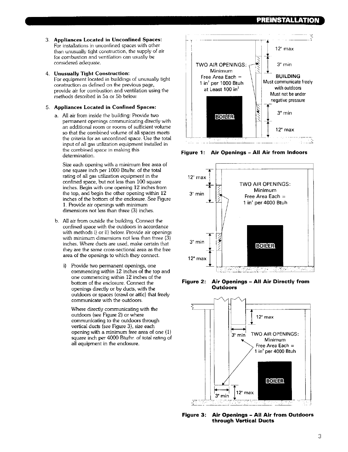
a. All air from inside the building: Provide two
permanent openings communicating directly with
an additional room or rooms of sufficient volume
so that the combined volume of all spaces meets
the criteria for an unconfined space. Use the total
input of all gas utilization equipment installed in
the combined space in making this
determination.
Size each opening with a minimum free area of
one square inch per 1000 Btu/hr. of the total
rating of all gas utilization equipment in the
confined space, but not less than I00 square
inches. Begin with one opening 12 inches from
the top, and begin the other opening within 12
inches of the bottom of the enclosure. See Figure
1. Provide air openings with minimum
dimensions not less than three (3) inches.
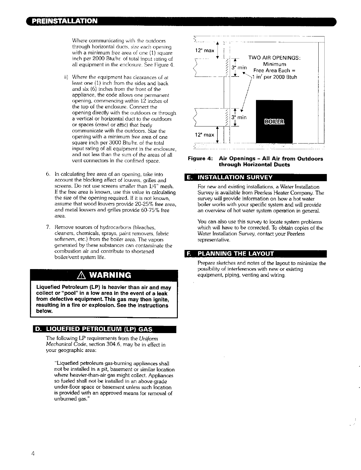
b. All air from outside the building. Connect the
confined space with the outdoors in accordance
with methods i) or ii) below. Provide air openings
with minimum dimensions not less than three (3)
inches. Where ducts are used, make certain that
they are the same cross-sectional area as the free
area of the openings to which they connect.
Provide two permanent openings, one
commencing within 12 inches of the top and
one commencing within 12 inches of the
bottom of the enclosure. Connect the
openings directly or by duets, with the
outdoors or spaces (crawl or attic) that freely
communicate with the outdoors.
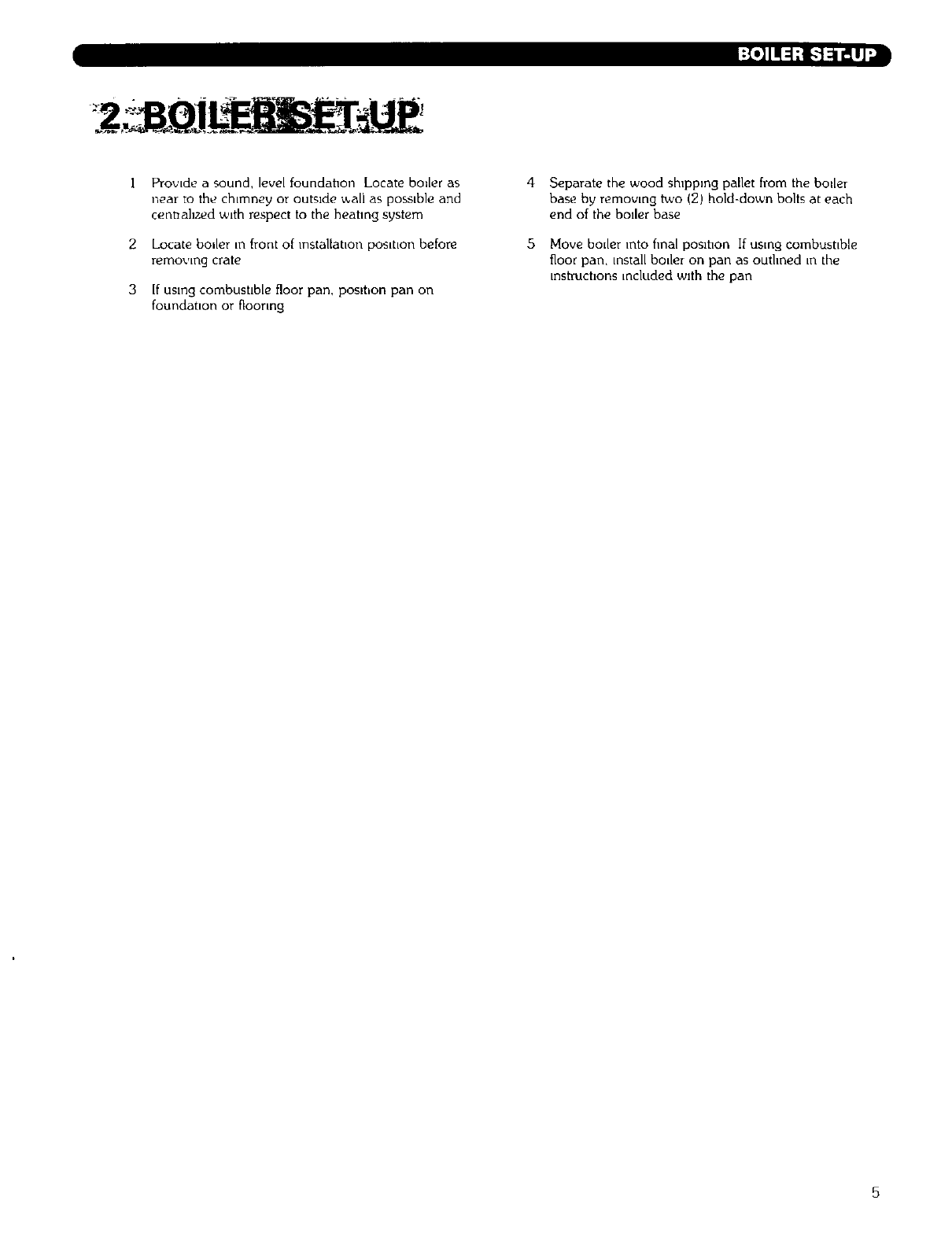
Where directly communicating with the
outdoors (see Figure 2) or where
communicating to the outdoors through
vertical ducts (see Figure 3), size each
opening with a minimum free area of one (I)
square inch per 4000 Btu/hr. of total rating of
all equipment in the enclosure.
i ?
I
12" max
TWO AIR OPENINGS:
Minimum
Free Area Each -
1 in2per 1000 Btuh
at Least 100 in2
BUILDING
Must communicatefreely
withoutdoors
Must not be under
negativepressure
12" max
Figure 1: Air Openings -All Air from Indoors
TWO AIR OPENINGS:
Minimum
Free Area Each -
1 in_per 4000 Btuh
Figure 2: Air Openings - All Air Directly from
Outdoors
Figure 3: Air Openings - All Air from Outdoors
through Vertical Ducts
6. :_ IIL_l_uf±lUHff±_ugl[e]L_l[_'q_|J;kVJ_k
7.
Where communicating with the outdoors
through horizontal ducts, size each opening
with a minimum free area of one (1) square
inch per 2000 Btu/hr of total input rating of
all equipment in the enclosure. See Figure 4.
ii) Where the equipment has clearances of at
least one (1) inch from the sides and back
and six (6) inches from the front of the
appliance, the code allows one permanent
opening, commencing within 12 inches of
the top of the enclosure. Connect the
opening directly with the outdoors or through
a vertical or horizontal duct to the outdoors
or spaces (crawl or attic) that freely
communicate with the outdoors. Size the
opening with a minimum free area of one
square inch per 3000 Btu!hr. of the total
input rating of all equipment in the enclosure,
and not less than the sum of the areas of all
vent connectors in the confined space.
In calculating free area of an opening, take into
account the blocking affect of louvers, grilles and
screens. Do not use screens smaller than i/4" mesh.
If the free area is known, use this value in calculating
the size of the opening required. If it is not known,
assume that wood louvers provide 20-25% free area,
and metal louvers and grilles provide 60-75% free
area.
Remove sources of hydrocarbons (bleaches,
cleaners, chemicals, sprays, paint removers, fabric
softeners, etc.) from the boiler area. The vapors
generated by these substances can contaminate the
combustion air and contribute to shortened
boiler/vent system life. I_ff±!_l_ll_[dl|ll:lt_VLelll
Liquefied Petroleum (LP) is heavier than air and may
collect or "pool" in a low area in the event of a leak
from defective equipment.This gas may then ignite,
resulting in a fire or explosion. See the instructions
below.
ii-i ..
12"maxl [ i 1--
, _t [jT TWO AIR OPENINGS: |
)1' Minimum l
Free Area Each =
in_per 2000 Btuh !
_ min
?
12" max
Figure 4: Air Openings - All Air from Outdoors
through Horizontal Ducts
For new and existing installations, a Water Installation
Survey is available from Peerless Heater Company. The
survey will provide information on how a hot water
boiler works with your specific system and will provide
an overview of hot water system operation in general.
You can also use this survey to locate system problems
which will have to be corrected. To obtain copies of the
Water Installation Survey, contact your Peerless
representative.
Prepare sketches and notes of the layout to minimize the
possibility of interferences with new or existing
equipment, piping, venting and wiring.
IIJ ! [o|lJ :l ;i I:ll]'.J :Eld:{o] ! ::[IILVA|_[€-r_,_..
The following LP requirements from the Uniform
Mechanical Code, section 304.6, may be in effect in
your geographic area:
"Liquefied peh'oleum gas-burning appliances shall
not be installed in a pit, basement or similar location
where heavier-than-air gas might collect. Appliances
so fueled shall not be installed in an above-grade
under-floor space or basement unless such location
is provided with an approved means for removal of
unburned gas."
l_.]llF'4T_'i:i_IrJ_
2
3
Provide a sound, level foundahon Locate boiler as
near to the chmney or outside v_ali as possLble and
cennahzed v_Jth respect to the heahng system
Locate boiler [n front of installation pos[hon before
_movll_g crate
If using combushble floor pan, poslhon pan on
foundat,on or flooring
4 Separate the wood shppmg pallet from the boiler
base by removing two (2) hold-down bolts at each
end of the boder base
5 Move boder into hnal poslhon If using combustLble
floor pan, install boder on pan as outhned ,n the
instructions included wlth the pan
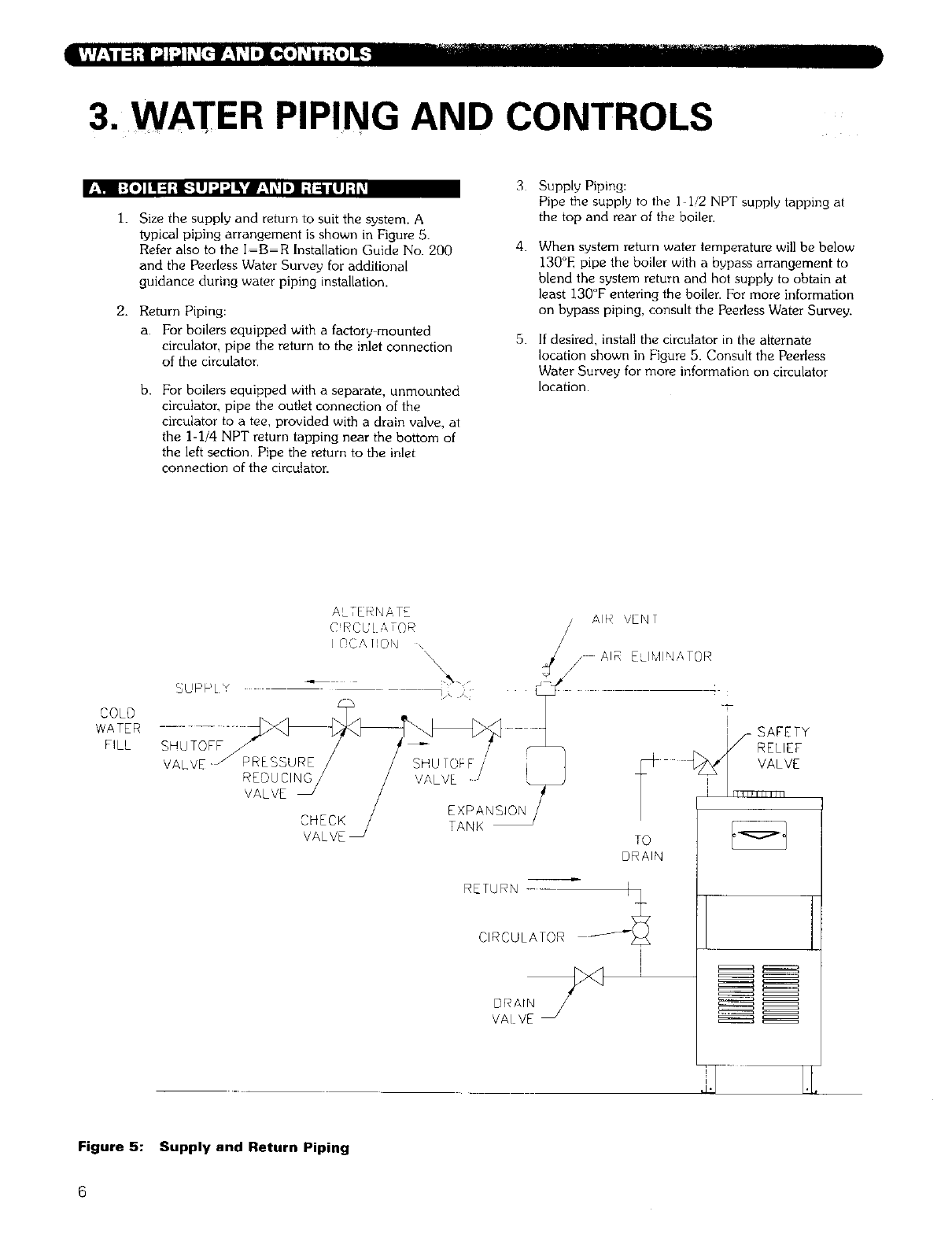
3. WATER PIPING AND CONTROLS
"-I [:{=]ll_;l[.-llJ'J_Jl_'m_,]l_ll] I;l:i[IJ;|k'
1. Size the supply and return to suit the system. A
t_pical piping arrangement is shown in Figure 5.
Refer also to the I-B-R Installation Guide No. 200
and the Peerless Water Survey for additional
guidance during water piping installation.
2. Return Piping:
a. For boilers equipped with a factory mounted
circulator, pipe the return to the inlet connection
of the circulator.
b. For boilers equipped with a separate, unmounted
circulator, pipe the outlet connection of the
circulator to a tee, provided with a drain valve, at
the 1-1/4 NPT return tapping near the bottom of
the left section. Pipe the return to the inlet
connection of the circulator.
3
4.
5.
Supply Piping:
Pipe the supply to the I i/2 NPT supply tapping at
the top and rear of the boiler.
When system return water temperature will be below
130°E pipe the boiler with a bypass arrangement to
blend the system return and hot supply to obtain at
least 130°F entering the boiler. For more information
on bypass piping, consult the Peerless Water Survey.
If desired, install the circulator in the alternate
location shown in Figure 5. Consult the Peerless
Water Survey for more information on circulator
location.
COLD
WATER
FILL
VAL VE
DRAIN
VAI VE J
TO
DRAIN
l
i
,7
Figure 5: Supply and Return Piping
6. Install this boiler so that the gas ignition system
components are protected from water (dripping,
spraying, etc ) during appliance operation and
service (circulator replacement, condensate trap,
control replacements, etc )
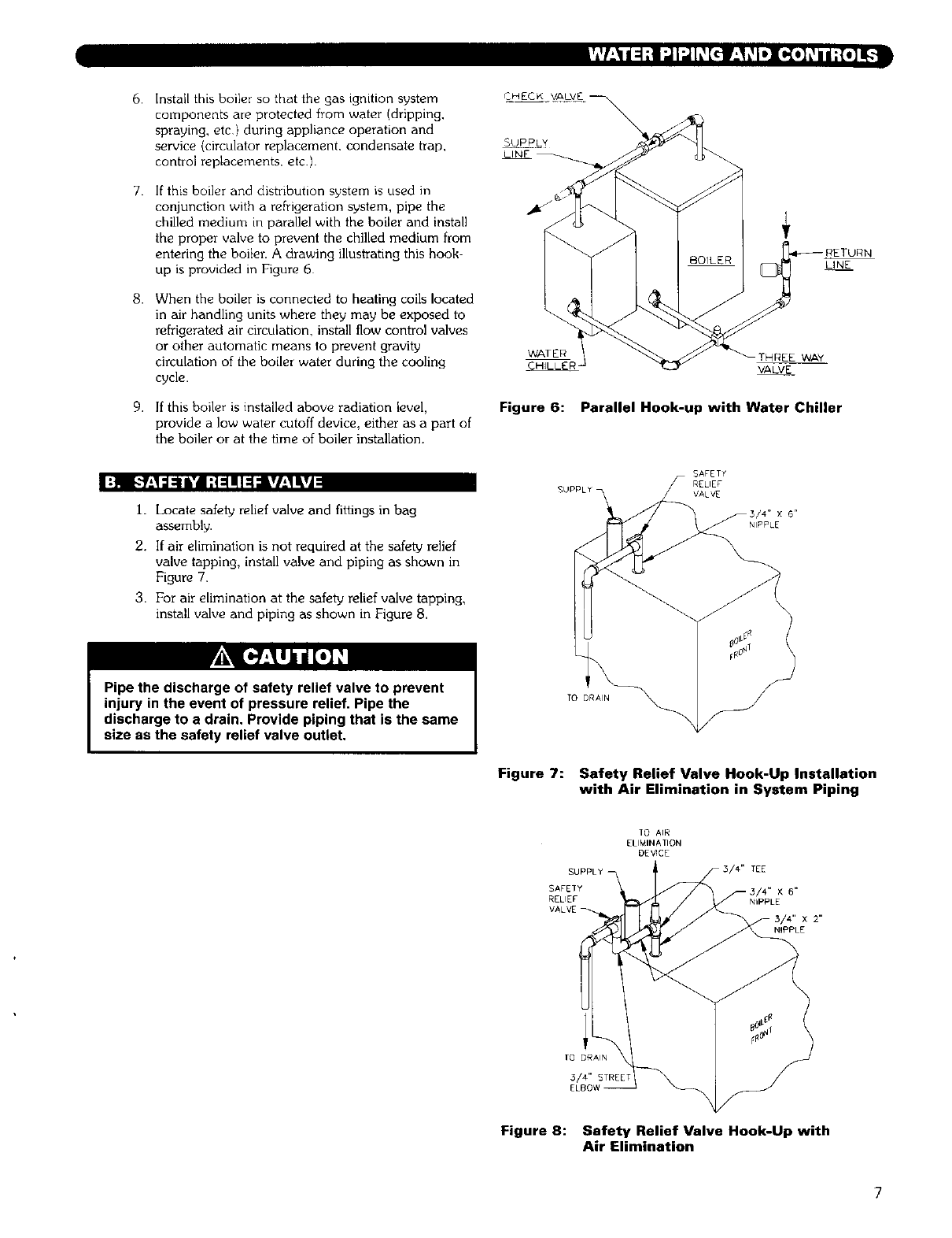
7. If this boiler and distribution system is used in
conjunction with a refrigeration system, pipe the
chilled medium in parallel with the boiler and install
the proper valve to prevent the chilled medium from
entering the boiler. A drawing illustrating this hook-
up is provided in Figure 6
8. When the boiler is connected to heating coils located
in air handling units where they may be exposed to
refrigerated air circulation, install flow control valves
or other automatic means to prevent gravity
circulation of the boiler water during the cooling
cycle.
9. If this boiler is installed above radiation level,
provide a low water cutoff device, either as a part of
the boiler or at the time of boiler installation.
C HECj VAILVEI
SUPPLY
LINE
LINE
WATER THREE WAY
_HILLER VALVE
Figure 6: Parallel Hook-up with Water Chiller
I:m l-'f!1=:lL'dI;t=l!l=l:l krl±lLvd
i I Locate safety relief valve and fittings in bag
assembly.
2. If air elimination is not required at the safety relief
valve tapping, install valve and piping as shown in
Figure 7.
3. For air elimination at the safety relief valve tapping,
install valve and piping as shown in Figure 8.
SAFETY
RELIEF
VALVE
x6"
NIPPLE
Pipe the discharge of safety relief valve to prevent
injury in the event of pressure relief, Pipe the
discharge to adrain. Provide piping that is the same
size as the safety relief valve outlet.
Figure 7: Safety Relief Valve Hook-Up Installation
with Air Elimination in System Piping
TO AIR
ELIMINATION
DE_CE
SUPPLY TEE
SAFETY X6 _
RELIEF NIPPLE
VALVE
NIPPLE
TO DRAIN
5/4" STREET
ELBO_
Figure 8: Safety Relief Valve Hook-Up with
Air Elimination
7
loll I'JI_IL'_[_ l;:[e];l v_[o]L'ql:lm]F.._'_"-]Ii :hVj_
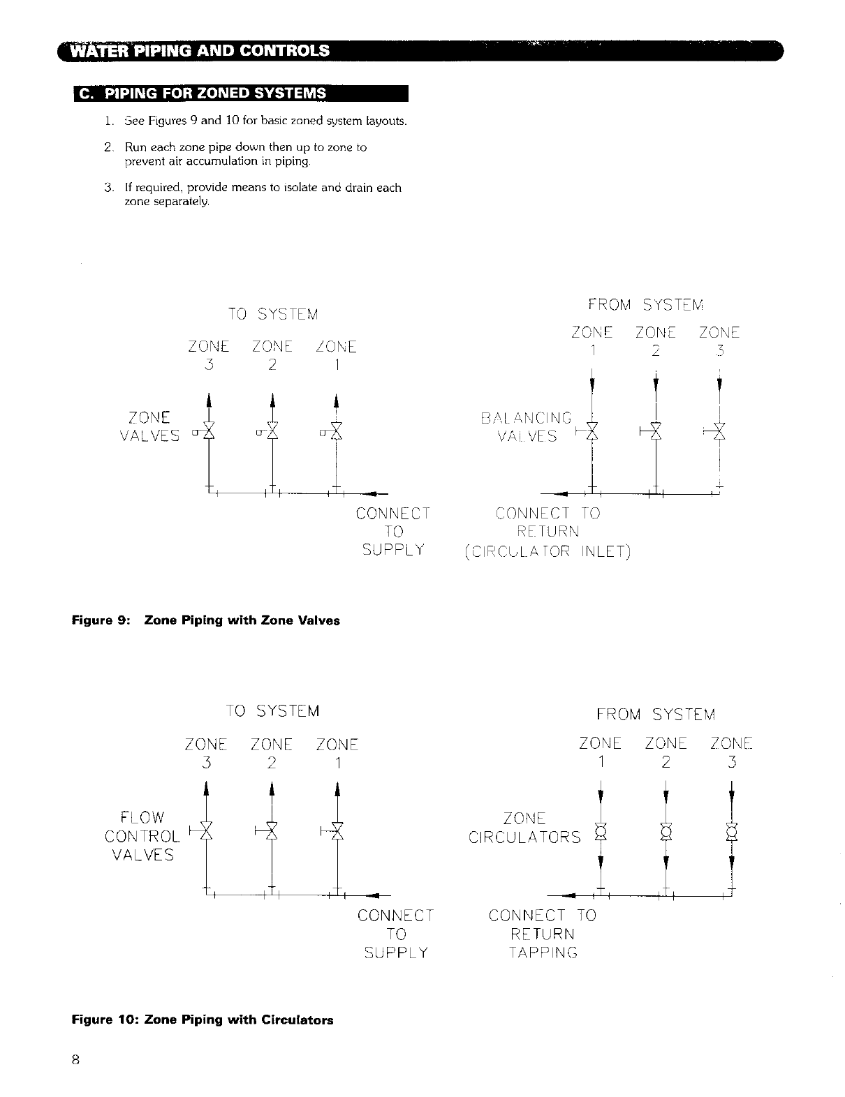
1. See Figures 9 and 10 for basic zoned system layouts.
2 Run each zone pipe down then up to zone to
prevent air accumulation in piping
3. If required, provide means to isolate and drain each
zone separately,
TO SYSTEM
ZONE ZONE ZONE
5 2 /
ZONE
VALVES
II
TO
SUPPLY
FROM SYSTEbl
BAL _,NCINO
VAi VES m',
CONNECT TO
RETURN
(CIRCULATOR INLET)
ZONE ZONE ZONE
I 2 3
I
I
±
Figure 9: Zone Piping with Zone Valves
TO SYSTEM
ZONE ZONE ZONE
5 2 1
FROM SYSTEM
ZONE ZONE
1 2 3
FLOW
CONTROL _]
VALVES
I- q
CONNECT
TO
SUPPLY
ZONE
CIRCULATORS
CONNECT TO
RETURN
TAPPING
Figure 10: Zone Piping with Circulators
8
I_ I:l;f:l:_,l: I;J;{e]i:_l,]i[o]_
1. Consult the tank manufacturer's instructions for
specific information relating to tank installation Size
the expansion tank for the required system volume
and capacity. See Table 8 in Section 10 for boiler
water capacity.
2. Expansion tanks are available with built-in fill valves
and check valves for reducing supply water pressure
and maintaining minimum system pressure. Check
the design features of the tank and provide valves as
necessary.
Refer back to Figure 5 for typical expansion tank piping.
I::m I I£qm]I:| =[o,]iI_ :ll:t ::1e]I_l,__ii =1;t I: I_,__ii ::1
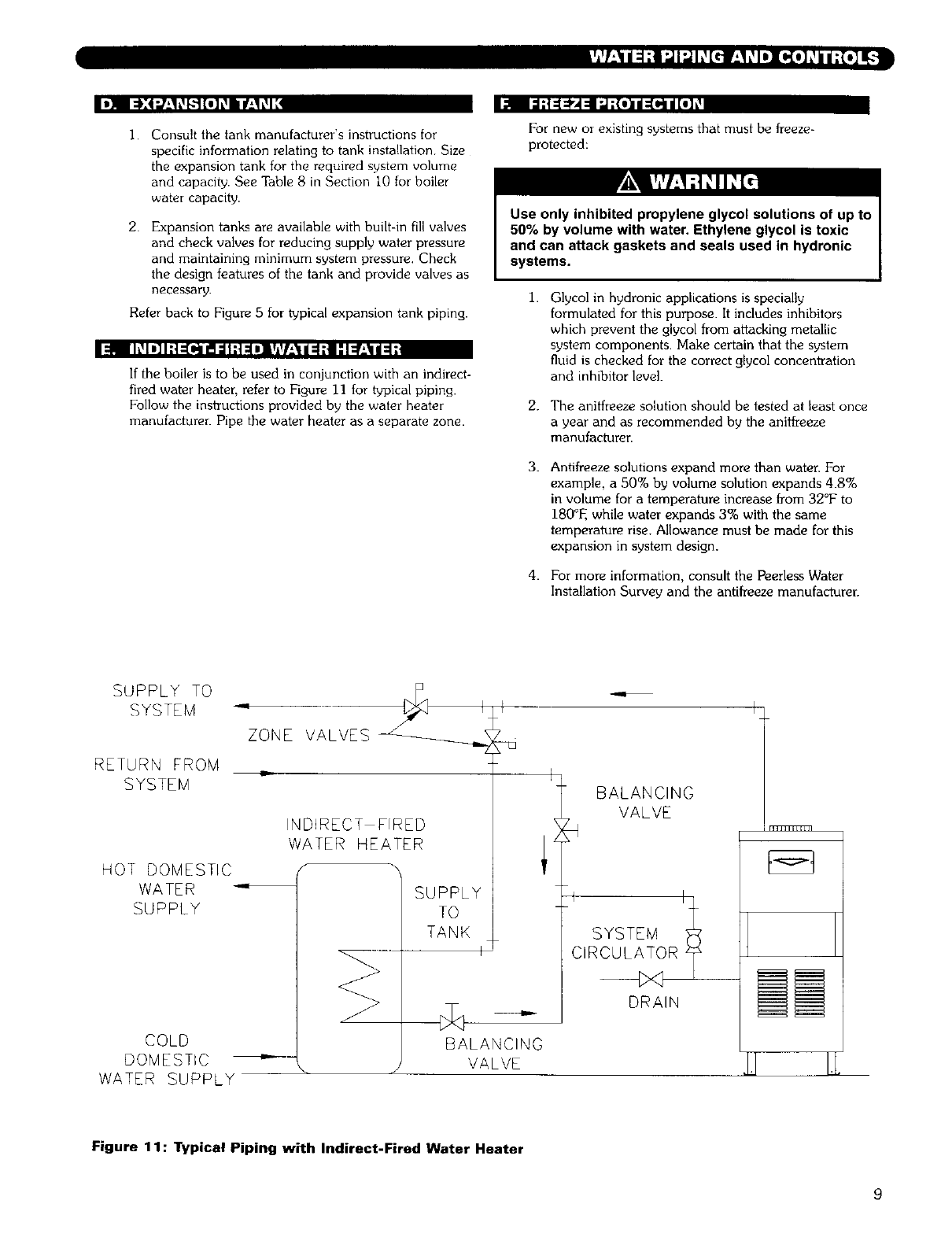
If the boiler is to be used in conjunction with an indirect-
fired water heater, refer to Figure 11 for typical piping.
Follow the instructions provided by the water heater
manufacturer. Pipe the water heater as a separate zone.
For new or existing systems that must be freeze-
protected:
Use only inhibited propylene glycol solutions of up to
50% by volume with water. Ethylene glycol is toxic
and can attack gaskets and seals used in hydronic
systems.
1. Glycol in hydronic applications is specially
formulated for this purpose. It includes inhibitors
which prevent the glycol from attacking metallic
system components. Make certain that the system
fluid is checked for the correct glycol concentration
and inhibitor level.
2. The anitfreeze solution should be tested at least once
a year and as recommended by the antifreeze
manufacturer.
3.
4.
Antifreeze solutions expand more than water. For
example, a 50% by volume solution expands 4.8%
in volume for a temperature increase from 32°F to
180°F, while water expands 3% with the same
temperature rise. Allowance must be made for this
expansion in system design.
For more information, consult the Peerless Water
Installation Survey and the antifreeze manufacturer.
SUPPLY TO
SYSTEM
RETURN FROM
SYSTEM
ZONE VALVES
INDIRECT FIRED
WATER HEATER
HOT DOMESTIC
WATER
SUPPLY
COLD
DOMESTIC _-
WATER SUPPLY
SUPPLY
TO
TANK
J
BALANCING
VALVE
]
BALANCING
VALVE
i I
SYSTEM
CIRCULATOR _
DRAIN
Figure 1 1: Typical Piping with Indirect-Fired Water Heater
9
Lt/:1_/Jl_[,':t
4; VENTING
|_,!1 h,'_ii::[d; f_,_II o] ;f_,_;Iil -"[o_o] g
1. The MIiMIH boiler is equipped with a built in draft
hood This device is designed to:
a provide for the ready escape of flue gases from
the boiler in the event of no draft.
b. prevent a backdraft [Tom entering the boilen
c. control stack draft during operation.
These tasks are accomplished without the extra
height requirements of a separate draft hood.
2. The draft hood relief opening is the large rectangular
passage at the front of the boiler. Make certain that
there are no obstructions to airflow in front of this
opening.
3. A vent safety shut off switch is located within the
draft relief opening to shut off the boiler in case of a
blocked vent condition. See Section 7B for details
regarding this device. See Figure 16 in Section 6
(Electrical) for spill switch location.
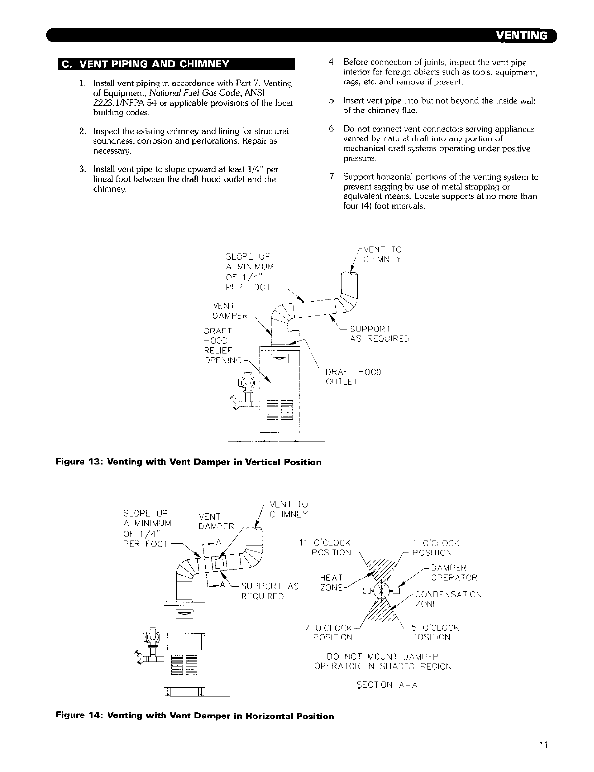
4. The vent damper can be mounted directly onto the
round draft hood outlet (vent connector) on top of
the boiler, or in vent piping close to the boiler. See
the Vent Damper Installation Instructions below.
].
2.
3.
4.
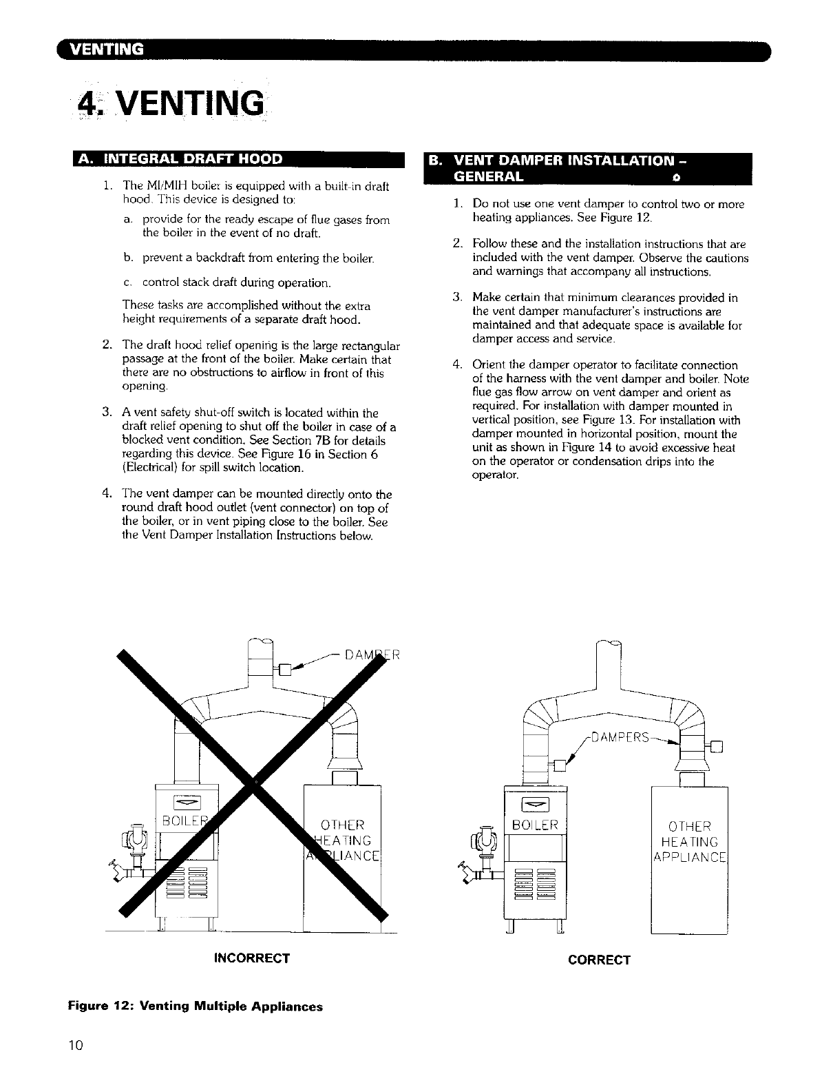
Do not use one vent damper to control two or more
heating appliances. See Figure 12.
Follow these and the installation instructions that are
included with the vent damper. Observe the cautions
and warnings that accompany all instructions.
Make certain that minimum clearances provided in
the vent damper manufacturer's instructions are
maintained and that adequate space is available for
damper access and service.
Orient the damper operator to facilitate connection
of the harness with the vent damper and boiler. Note
flue gas flow arrow on vent damper and orient as
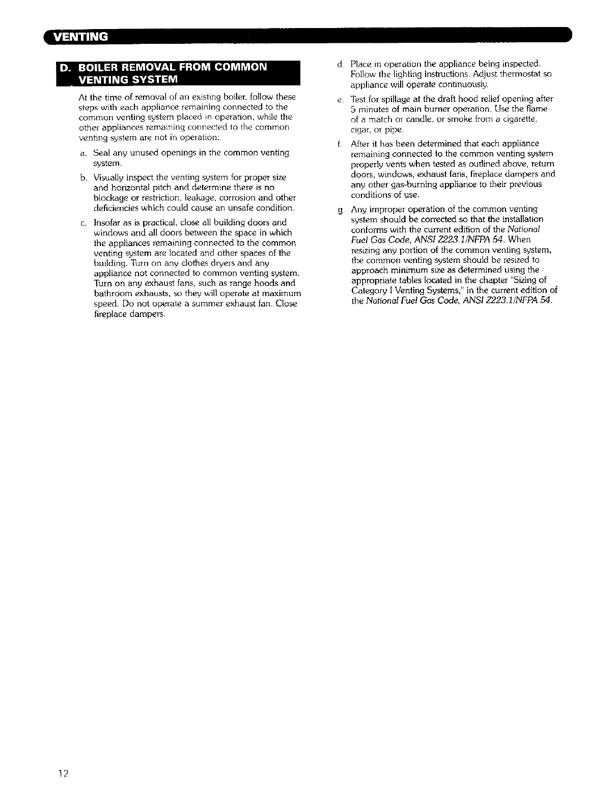
required. For installation with damper mounted in
vertical position, see Figure 13. For installation with
damper mounted in horizontal position, mount the
unit as shown in Figure 14 to avoid excessive heat
on the operator or condensation drips into the
operator.
BOILER
c:::::::_ c:::::::_
c:::=_ c:::::_
c:::::::_ c:::::::_
OTHER
HEATING
&PPLIANCE
INCORRECT CORRECT
Figure 12: Venting Multiple Appliances
10
_o,,NkVJ:h,_/uI:JI:,,]h,1[€_V_*l_._ID][o,]-"I hVjh._I_"
1. Install vent piping in accordance with Part 7. Venting
of Equipment, National Fuel Gas Code, ANSI
Z223. I/NFPA 54 or applicable provisions of the local
building codes.
2. Inspect the existing chimney and lining for structural
soundness, corrosion and perforations. Repair as
neces_Fy.
3. Install vent pipe to slope upward at least I/4" per
lineal foot between the draft hood outlet and the
chimney.
4.
5.
6.
7.
Before connection of joints, inspect the vent pipe
interior for foreign objects such as tools, equipment,
rags, etc. and remove if present.
Insert vent pipe into but not beyond the inside wall
of the chimney flue.
Do not connect vent connectors serving appliances
vented by natural draft into any portion of
mechanical draft systems operating under positive
pressure.
Support horizontal portions of the venting system to
prevent sagging by use of metal strapping or
equivalent means. Locate supports at no more than
four (4) foot intervals.
SLOPE uP
A MINIMUM
OF 1/4"
PER FOOT
VENT
DAMP
DRAFT _ _ f¢3
HOOD
RELIEF
flVENT TO
CHIMNEY
SUPPORT
AS REQUIRED,
DRAFT HOOD
OUTLET
Figure 13: Venting with Vent Damper in Vertical Position
SLOPE UP VENT
A MINIMUM DAMPER
OF I/4"
PER FOOT_,,_
_VENT TO
CHIMNEY
11 O'CLOCK i O'CLOCK
POSITION POSITION
!
SUPPORT AS
REQUIRED
ri
HEAT
_CONDENSATION
ZONE
7O'CLOCK _5 O'CLOCK
POSITION POSIT'ON
DO NOT MOUNT DAMPER
OPERATOR IN SHADED REGION
SECTION A
Figure 14: Venting with Vent Damper in Horizontal Position
11
At the time of removal of an existing boiler, follow these
steps with each appliance remaining connected to the
common venting system placed in operation, while the
other appliances remaining connected to the common
venting system are not in operation:
a. Seal any unused openings in the common venting
system.
b, Visually inspect the venting system for proper size
and horizontal pitch and determine there is no
blockage or restriction, leakage, corrosion and other
deficiencies which could cause an unsafe condition.
C_ Insofar as is practical, close all building doors and
windows and all doors between the space in which
the appliances remaining connected to the common
venting system are located and other spaces of the
building. Turn on any clothes dryers and any
appliance not connected to common venting system.
Turn on any exhaust fans, such as range hoods and
bathroom exhausts, so they will operate at maximum
speed. Do not operate a summer exhaust fan. Close
fireplace dampers.
d
e.
g.
Place in operation the appliance being inspected.
Follow the lighting instructions. Adjust thermostat so
appliance will operate continuously.
Test for spillage at the draft hood relief opening after
5 minutes of main burner operation. Use the flame
of a match or candle, or smoke from a cigarette,
cigar, or pipe,
After it has been determined that each appliance
remaining connected to the common venting system
properly vents when tested as outlined above, return
doors, windows, exhaust fans, fireplace dampers and
any other gas-burning appliance to their previous
conditions of use.
Any improper operation of the common venting
system should be corrected so that the installation
conforms with the current edition of the National
Fuel Gas Code, ANSI 7-223.1/NFPA 54. When
resizing any portion of the common venting system,
the common venting system should be resized to
approach minimum size as determined using the
appropriate tables located in the chapter "Sizing of
Category I Venting Systems," in the current edition of
the National Fuel Gas Code, ANSI Z223.1/NFPA 54.
12
2
3
4
5
SLZeand w,-_tal[the gas supply plpmg properly in
ordeT to provide a supply of gas sufflc,ent to meet
the maximum demand wlthout undue loss of
pressure between the meter and the boder
Determine the volume of gas to be provlded to the
boller in cublc feet per hour To obtain this value,
thv]de the Btu per hour rating (on the boiler rating
plate) by the heating value ot the gas ]n Btu per
cubic feet Obtain the heating value of the gas from
the gas suppher As an alternatwe use Table 1 2 or
3 on the next page to obtain the volume of gas to be
p_ovLded to the boder
Use the value obtained above as the bas_s for p_pmg
SLZmg SLze the gas piping m accordance w_th Table
4 Consult the Natzonal Fuel Gas Code ANSI
Z223 I,'NFPA 54 for other slzlng optmns
Locate the drop pipe adjacent to, but not m front of
the boder
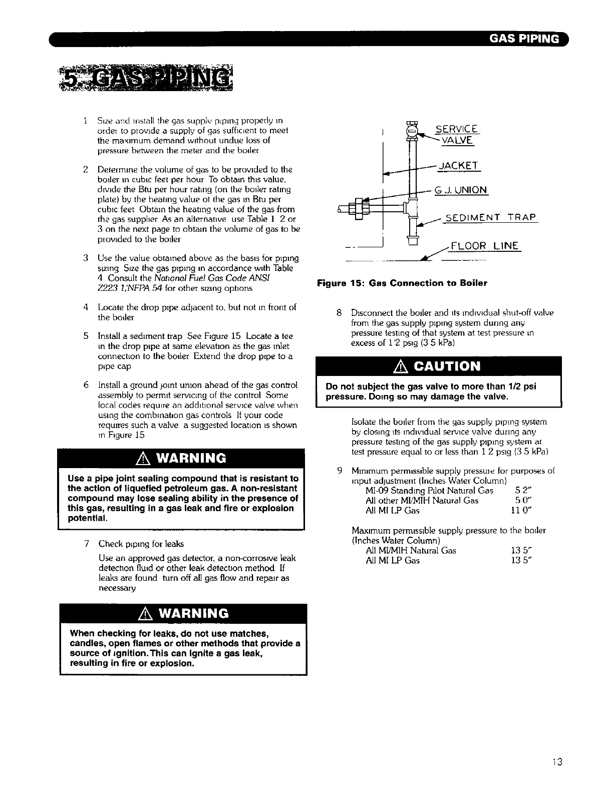
Install a sedlment trap See Figure 15 Locate a tee
m the drop plpe at same elevatlon as the gas inlet
connechon to the bo_Ler Extend the drop p_pe to a
pLpe cap
Install a ground joint umon ahead of the gas control
assembly to permit serwcmg of the control Some
Localcodes reqmre an additional serwce valve when
using the combmat,on gas controls If your code
reqmres such a valve a suggested IocatLon Lsshown
in FLgure 15
Use a pipe joint sealing compound that is resistant to
the action of tiquefied petroleum gas. A non-resistant
compound may lose sealing ability in the presence of
this gas, resulting in a gas leak and fire or explosion
potential.
Check pLpmg for leaks
Use an approved gas detector, a non-corroslve leak
detectlon flu,d or other leak detecUon method If
leaks are found turn off all gas flow and repalr as
necessal_j
j _ SERVICE
-----JAC K ET
_GJ. UNION
_ I _fSEDIMENT TRAP
_/FLOOR LINE
Figure 15: Gas Connection to Boiler
8 Disconnect the boiler and its ]ndlwdual shut-off valve
from the gas supply piping system dunng any
pressure testLng of that system at test pressure m
excess of i '2 psLg (3 5 kPa)
Do not subject the gas valve to more than 1/2 psi
pressure. Doing so may damage the valve.
Isolate the boiler from the gas supply p_pmg system
by closing _ts _ndw_dual serwce valve dunng any
pressure testing of the gas supply plpmg system at
test pressure equal to or less than i 2 pslg (3 5 kPa)
9 Mlmmum permlsslble supply pressule for purposes of
,nput adjustment (Inches Water Column)
MI-09 Standing Pdot Natural Gas 5 2"
All other MI/MIH Natural Gas 5 0"
All MI LPGas II 0"
Maximum permlsslble supply pressure to the boder
(Inches Water Column)
All MI/MIH Natural Gas 13 5"
All MI LP Gas 13 5"
When checking for leaks, do not use matches,
candles, open flames or other methods that provide a
source of =gnition.This can ignite a gas leak,
resulting in fire or explosion.
13
[tl :I-2[_igl_tl
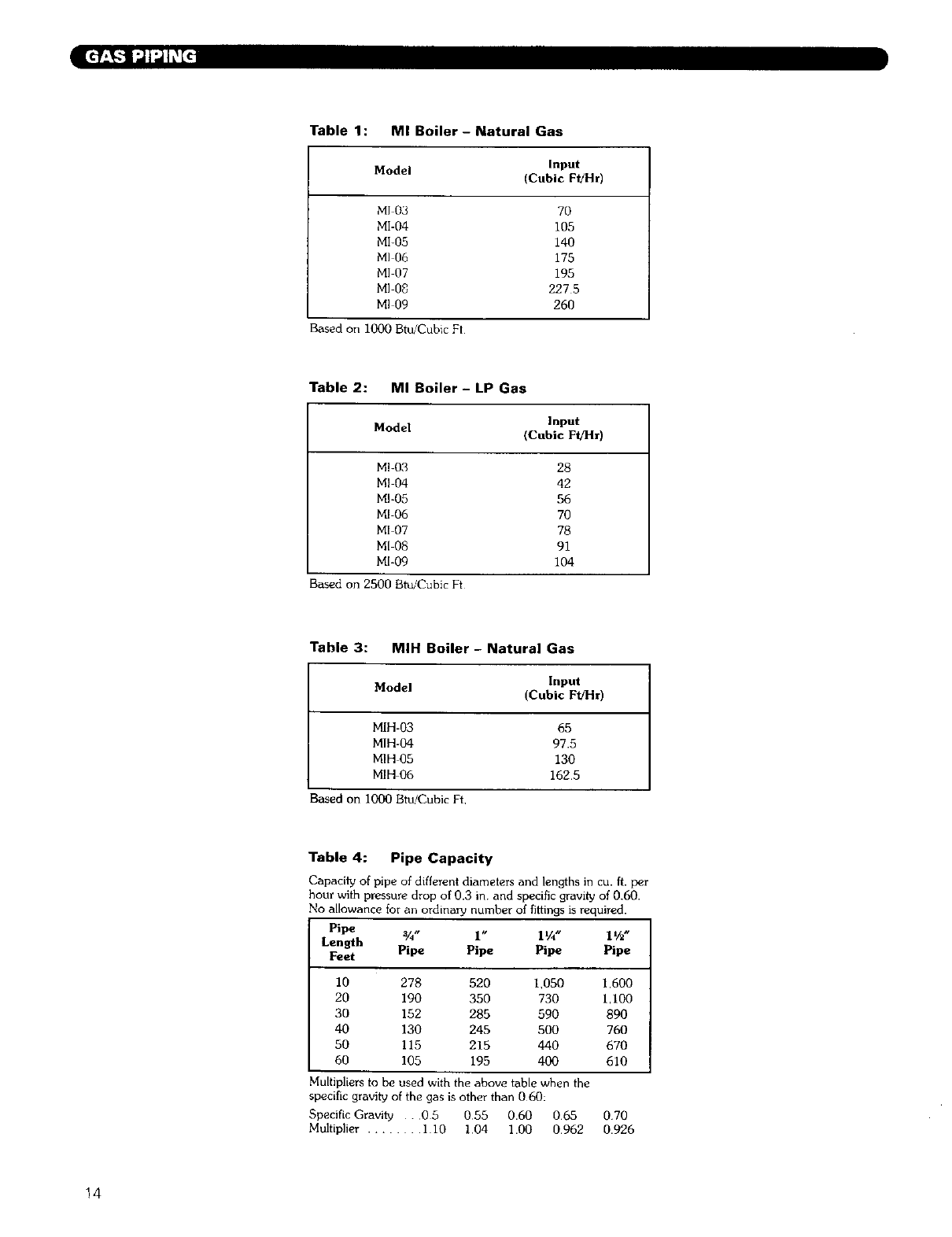
Table 1: MI Boiler- Natural Gas
Model Input
(Cubic F_Hr)
MI 03 70
MI-04 105
MI-05 140
MI Ofi 175
MI 07 195
M] 0_ 227 5
MI 09 260
Based on i000 Btu/Cubic Ft
Table 2: MI Boiler - LP Gas
Model Input
(Cubic FI/Hr)
Ml-03 28
MI 04 42
MI-05 56
MI-06 70
MI-07 78
M[ 08 91
MI-09 104
Based on 2500 Bt_ICubicFt
Table 3: MIH Boiler - Natural Gas
Model Input
(Cubic FffHr)
MIH-03 65
MIH-04 97.5
MIH 05 130
MIH 06 162.5
Based on 1000Btu/CubicFt,
Table 4: Pipe Capacity
Capacity of pipe of different diameters and lengths in cu. ft. per
hour with pressure drop of 0.3 in and specific gravity of 0.60.
No allowance for an ordinary number of fi_ings is required.
Pipe V4" l" 11/4" 11/2u
Length
Feet Pipe Pipe Pipe Pipe
I0 278 520 1,050 1,600
20 190 350 730 1,100
30 152 285 590 890
40 130 245 500 760
50 115 215 440 670
60 105 195 400 610
Multipliers to be used with the above table when the
specific gravity of the gas is other than 060:
Specific Gravity . 0 5 055 0.60 065 070
Multiplier ........ 110 1,04 1.00 0.962 0.926
14
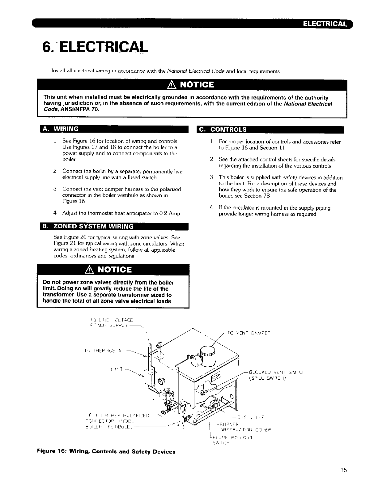
6.*ELECTRICAL
Install all elechlcal wrong m accoldance wLth the National Elecmcal Code and local requirements
This umt when installed must be electrically grounded in accordance with the requirements of the authority
having JUrlSdtctton or, in the absence of such requirements, with the current edlbon of the National Electrical
Code, ANSI/NFPA 70.
r_,! iv=,il;llL_[€ _.41 [*(o] L_iiII-'{e]I_
2
3
See Figure 16 for locatEon of wrong and conh'ols
Use Figures 17 and 18 to connect the boder to a
power supply and to connect components to the
boiler
Connect the bo=le_ by a separate, permanently live
electrLcal supply hne with a fused switch
Connect _he vent damper harness to the polarLzed
connector Lnthe boder vest=bule as shown m
Figure 16
4 Adjust the thermostat heat antlcipator to 0 2 Amp
1
2
3
4
For proper locatlon of controls and accessories refer
to Flgure 16 and Section I i
See the attached control sheets for specific details
regarding the instal]atlon of the various conlzols
Thin boiler is supphed wlth safety dev=ces m addttlon
to the hmlt For a descnpt_on of these dewces and
how they work to ensure the safe operatlon of the
boiler, see Secuon 7B
If the clrculator [smounted m the supply plpmg,
provLde longer wrong harness as requLred
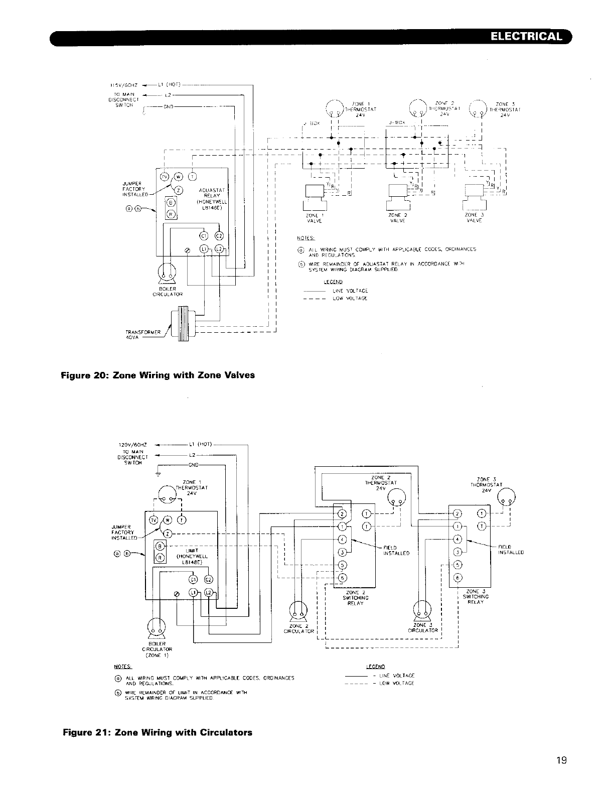
See Figure 20 for typLcal wiring w=th zone valves See
Figure 21 for t_pLcal wrong with zone cLrculators When
wLrlng a zoned heating system, follow all apphcable
codes ordinances and regulations
Do not power zone valves directly from the boiler
limit. Doing so will greatly reduce the life of the
transformer Use a separate transformer sized to
handle the total of all zone valve electrical loads
i9 LIHL OL IACE
T,:, THEPrlOST_T _
Lit IIT -_._
C, Jr I-L_IPE_ POL'I:t2ED
F _,r Jr JEC T,)_' iIPI3BDL
E JlLC_ P_ /IBLILE,
_- _ TO ','EN7 DAMPEP
_ "---... _ GLC,CXED _Er_T SWITCH
DB_E_.',' nbr4 CO_L_
LeL_t IE _JCILLOU T
Figure 16: Wiring, Controls and Safety Devices
15
CONNECTION DIAGRAM
24V THERMOSTAT (BY OTHERS)
.... LB148£ C_81NATIO_i DISCONNECT
"r.....
NSTALLF_ _ 60 LI BK
R SUPgLY L2 SER_C£
eK_ THESE]_TO--
0{,.!B.i l 'i
I _ERMO¢OUpI "_
L2T22_ ,
Ii
CONNECTOR rifle RelJ_e,4JTS_l F _=t__
wV#_lTE
C_NEC1]ON DIAGRAM LEG{.ND 0 ORANCE
BL BLUE
-- UNE VOLTAGE _IZE _¢ A_ TYPE TW, TFF'N OR 1EW/A_ _IRE
-- UNE VOLTAGE _ZE 16-18 AWG TYPE I%V TFFN OR I_W/A_%a V_RE
-- LOW '_LTAGE SIZE 18 A_G TYPE TC CABLE
-- -- LOW VOLTAGE SIZE 16-18 AWG WR[ TYPE TEW/AV_, TFFN _R£
NOTESm
I) ALL _RING MUST COMPLY V_IH APPUANC[ CODES, ORDINANCES AND REGULATIONS
2) IF ANY OF 1HE ORIGINAL MRE AS SUpPU_O _4TH THE ApPLiANCE MUST BE
REPLACED, IT MUST B_ REPLACED V4T_ _RE AS SHO_
LADDER OIAGRAM
115/60/i L2
pOV_ER
SUPPLy
C_ C2
FUSE{) RI
DISCONNECT SER_CE
S_TCH S_4TCH pR_MAR Y
TR ANS_Oei4 ER
SZCONDARY
I B2,
I
I PRS BvS
L 1%.
RZ LIMIT I
,
IT_ERNOCOUP_
LAODER DIACRAM I[G_NO I
-- 120v INTERNAL WIRIN_ i
-- 120V EXTERNAL _IRtNG [
24V INI_RNAL _,tRING
-- 24V [XERNAL _IRINg
---- MIU IVOLT _RING
0 L_I4BE _RMtNAL
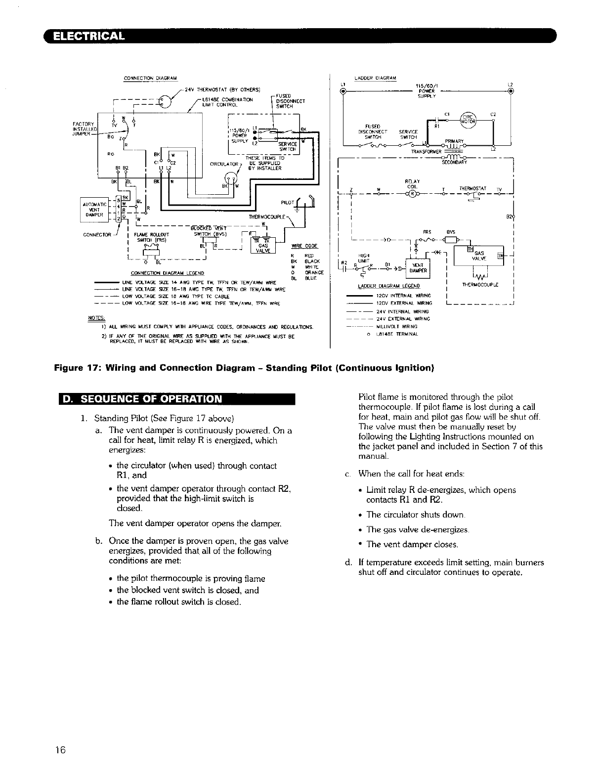
Figure 17: Wiring and Connection Diagram -Standing Pilot (Continuous Ignition)
I'_ F.']:[olli:l_[o,]:l [o]d[oir,,l=l;__41/[o]_
I. Standing Pilot (See Figure 17 above)
a. The vent damper is continuously powered. On a
call for heat, limit relay R is energized, which
energizes:
• the circulator (when used) through contact
R1, and
• the vent damper operator through contact R2,
provided that the high-limit switch is
closed.
The vent damper operator opens the damper.
b. Once the damper is proven open, the gas valve
energizes, provided that all of the following
conditions are met:
• the pilot thermocouple is proving flame
• the blocked vent switch is closed, and
• the flame rollout switch is closed.
Pilot flame is monitored through the pilot
thermocouple. If pilot flame is lost during a call
for heat, main and pilot gas flow will be shut off.
The valve must then be manually reset by
following the Lighting Instructions mounted on
the jacket panel and included in Section 7 of this
manual.
c. When the call for heat ends:
• Limit relay R de-energizes, which opens
contacts RI and R2.
• The circulator shuts down.
• The gas valve de-energizes.
• The vent damper closes.
d. If temperature exceeds limit setting, main burners
shut off and circulator continues to operate.
16
" i:!!;["_e_2_
CONN£CTI_ DIAGR_ L*_[R [_AGRAM
L 1 11p_o_45_LR_1 L2
¢1 C2
FUSED RI
D'S_EC T_5_ T_I_
T ....
HIGH I
R U_IIT
28R B! I I
LAD{)_R DIAGRAM L[G[NO [ 1_+41T_ __AM_ I
-- ND I
-- 120V INT_RN_L I_IR1NG I _PPILOT
-- t20v [XT_RHAL_RIN_ L _BNC)]
---- _4V iN.HAL _4RIN_
-- -- 24V [XTERNAL _I_IN_
....... _>iLOT _RIN@
oLO14_ T_R_IN_-
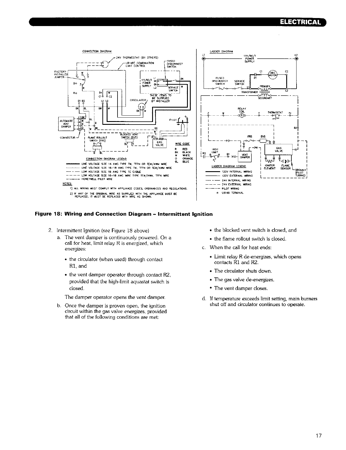
Figure 18: Wiring and Connection Diagram - Intermittent Ignition
2. Intermittent Ignition (see Figure 18 above)
a. The vent damper is continuously powered. On a
call for heat, limit relay R is energized, which
energizes:
• the circulator (when used) through contact
RI, and
• the vent damper operator through contact R2,
provided that the high-limit aqu_stat switch is
closed.
The damper operator opens the vent damper.
b. Once the damper is proven open, the ignition
circuit within the gas valve energizes, provided
that all of the following conditions are met:
• the blocked vent switch is closed, and
• the flame rollout switch is closed.
c. When the call for heat ends:
• Limit relay R de-energizes, which opens
contacts R1 and R2.
• The circulator shuts down.
• The gas valve de-energizes.
• The veat damper closes.
d. If temperature exceeds limit setting, main burners
shut off and circulator continues to operate.
17
START
APPLY24 VAC ITO APPLIANCE
ITHERMOSTAT ICALLS FOR HEAT
TRIAL
FOR
IGNITION
MAIN
BURNER
OPERATION
I FLAME SIGNAL
DETECTED_ NO
I INTERNAL CHECK OKAY? INO
_YES
I • PILOT VALVE OPENS I
•IGNITER POWERED
PILOTLIGHTSAND FLAME NO
IS SENSED DURING /_-_
TRIAL FOR IGNITION?
YES
[ " IGNITER OFF I• MAIN VALVE OPENS
•WAIT FOR FLAME SIGNAL
TO DISAPPEAR
•PILOT VALVE/IGNITER
REMAIN OFF
/
•PILOT VALVE CLOSES L
/
•IGNITER OFF
[THREE-SECOND FLAME JFAILURE RECYCLE DELAY
I FLAME SIGNAL LOST?
I THERMOSTATCALL FOR IHEAT ENDS
I•MAIN AND PILOT VALVES CLOSE
END
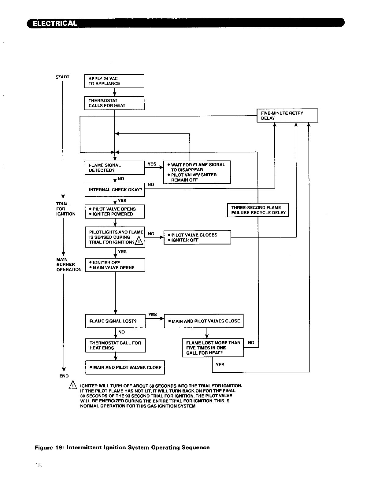
L/_ IGNITER WILL TURN OFF ABOUT 30 SECONDS INTO THE TRIAL FOR IGNITION.
IF THE PILOT FLAME HAS NOT LIT, IT WILL TURN BACK ON FOR THE FINAL
30 SECONDS OF THE 90 SECOND TRIAL FOR IGNITION. THE PILOT VALVE
WILL BE ENERGIZED DURING THE ENTIRE TRIAL FOR IGNmON. THIS IS
NORMAL OPERATION FOR THIS GAS IGNITION SYSTEM.
I
•MAIN AND PILOT VALVES CLOSE I
I
FLAME LOST MORE THAN NI NO
FIVE TIMES IN ONE
CALL FOR HEAT?
I l
FIVE-MINUTEDELAYRETRY I
A
Figure 19: Intermittent Ignition System Operating Sequence
!8
I15V/60HZ _LI (HOT}
TO MAIN _ _2
DISCONNECT
g_TCH J GND
dUMPER
FACTORY
INSTALLED--
F -
I F
I !
AOOASTAT
RELAY
(HONEYWELL
LS148E)
// _ZONE I/_ _ ZONE 2 \ ZONE 3
,_× I I j _c× I
[ [ ' i I •
- I I q I I 7 1
[ 7 I L _ , 71 1 _
v I I y I y] l
[
ZONE , ZONE 2 ZONE 3
VALVE VALVE VALVE
NO_
_ AlL WIRING MUST COMPLY WITH APPLICABLE CODEg• OROLNANCES
AND PEGULATIONS
(_ WIRE REMAINDER OF AQUASTAT RELAY IN ACCORDANC_ WITH
SYSTEM WIRING DIAGRAM SUPPLIED
kkGX.N_
UN_ VOLTAGE
LOW VOLTAGE
Figure 20: Zone Wiring with Zone Valves
I20V/6OHZ _LI (_OT)--
TO MAIN
DISCONNECT L2
SWITCH _GND
ZONE 1
THERMOSTATm _ 24V
I I
JUMPER
FACTORy
LIMI T(HONEYWELL
LBI48E)
L
i
1
I
1I
I
ZONE 2 i
CIRCULATOR i
BOILER
CIRCULATOR
(ZONE I)
(_) ALL ',_RING MUST COMPLY '_TH APPLICABLE CODES, ORDINANCES
AND REGULATIONS
(_ _RE REMAINDER OF LIMIT IN ACCORDANCE _TN
SYSTEM _R_NC DIAGRAM SUPPLIED
ZONE 2
THER_OvSTAT
I_ -_ [NSTALLE O
#
S_ICHING
RELAY
ZON£ 3
CIRCULATO_ I
L L ............. •
L .........
- LINE VOLTAGE
LOW VOLTAGE
ZON[ 3
IHERMOSTAI
24V
INSTALLED
S_TCHING
RELAY
Figure 21: Zone Wiring with Circulators
19
7. START-UP PRO_GI RES +
f-'l [a"[o) L'+I"JII:IIIIh'_[€"li l -"I=IIh';F-"+lIr-"1! l;_li to] L_
1
2
3
4
5
Cont£rm that all water gas and electnclly are
turned off
Inspect the boiler combu,,t]on chamber for foreLgn
objects and remove if present
Check phystcal cond]tton of burners and pilot Make
certain that there are no unusual bends or
perforations m the burners or pilot Replace
components if necessary
Verify that water pLpmg venting gas ptpmg and
electrical wlrLng and components are mstalled
properly Refer back to prevtou+ sections of these
mstructtons as well as egutpmen[ manufacturer's
mstruchons as necessary
Fill the boiler and system with water making certain
to vent all air from all points in the system To check
water level in the system open and close each vent
m the system Water should exit from each vent
when it _sopened
The pressure reducing valve on the fill hne w=ll
typically allow the system to be hlled and pressurized
to 12 pm Consult the vab+,e and expansion tank
manufacturer for mote specff,c reformation
Check lotnts and fitting+ throughout the system for
Leaks [f leaks are found dram the system and repatr
as required
9
i0
11
12
13
Connect a manometer to the gas val_,e on the valve
outlet (ga, manifold) Use the 1 8 NPT tappLng
prowded
Confirm that the gas supply pressure to the boiler Rs
above the mlmmum and below the maximum values
for the gas being used See the end of Section 5 for
these values If a supply pressure check _s reqmred
_solare the boiler and gas valve before performing
the pressure check If the supply pressure is too high
or too low contact the gas supplier
Turn on electrtctw and gas to boiler
Light the boiler by followmg the Llghnng Operating
Instrucnons label mounted to the jacket panel The
Lnltlal Ignition may requve several tries as the piping
ts purged of atr
Use the sequence descnptlons m Figures 17 18 and
19 in Section 6 (Electrical) to follow l,ght-off and
shutdown sequences and to asmst m dmgnosmg
problems If the boiler does not funcbon properly
consult Section 8, Troubleshooting
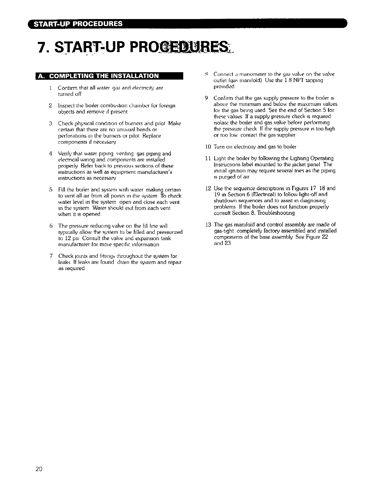
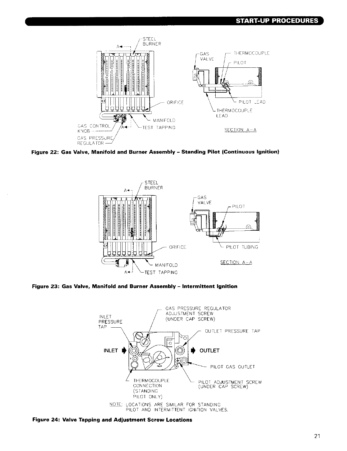
The gas manifold and control assembly are made of
gas-tlght completely factory assembled and installed
components of the base assembly See Figure 22
and 23
2O
!UUUL L4
'_ PILOI _EAD
THERMOCOUPLE
LEAD
SECTION A A
Figure 22: Gas Valve, Manifold and Burner Assembly - Standing Pilot (Continuous Ignition)
-GAS
VALVE
S ORIFICE
_\ MAN,FOLD
A"_ _TEST TAPPING
PILOT TUBING
SECTION A A
Figure 23: Gas Valve, Manifold and Burner Assembly - Intermittent Ignition
7 GAB PRESSURE REGULATOR
/ADJUSTMENT SCREW
22_BURE /_UNOERCA_SCREW)
TAPLET_ouUTLETIN TLET PRESSURE TAP
LTHERMOCOUPLE _ PILOT ADJUSTMENT SCREW
CONNECTION (UNDER CAP SCREW)
(STANDING
PILOT ONLY)
NOTE: LOCATIONS ARE SIMILAR FOR STANDING
PILOT AND INTERMITTENT IGNRION VALVES.
Figure 24: Valve Tapping and Adjustment Screw Locations
21
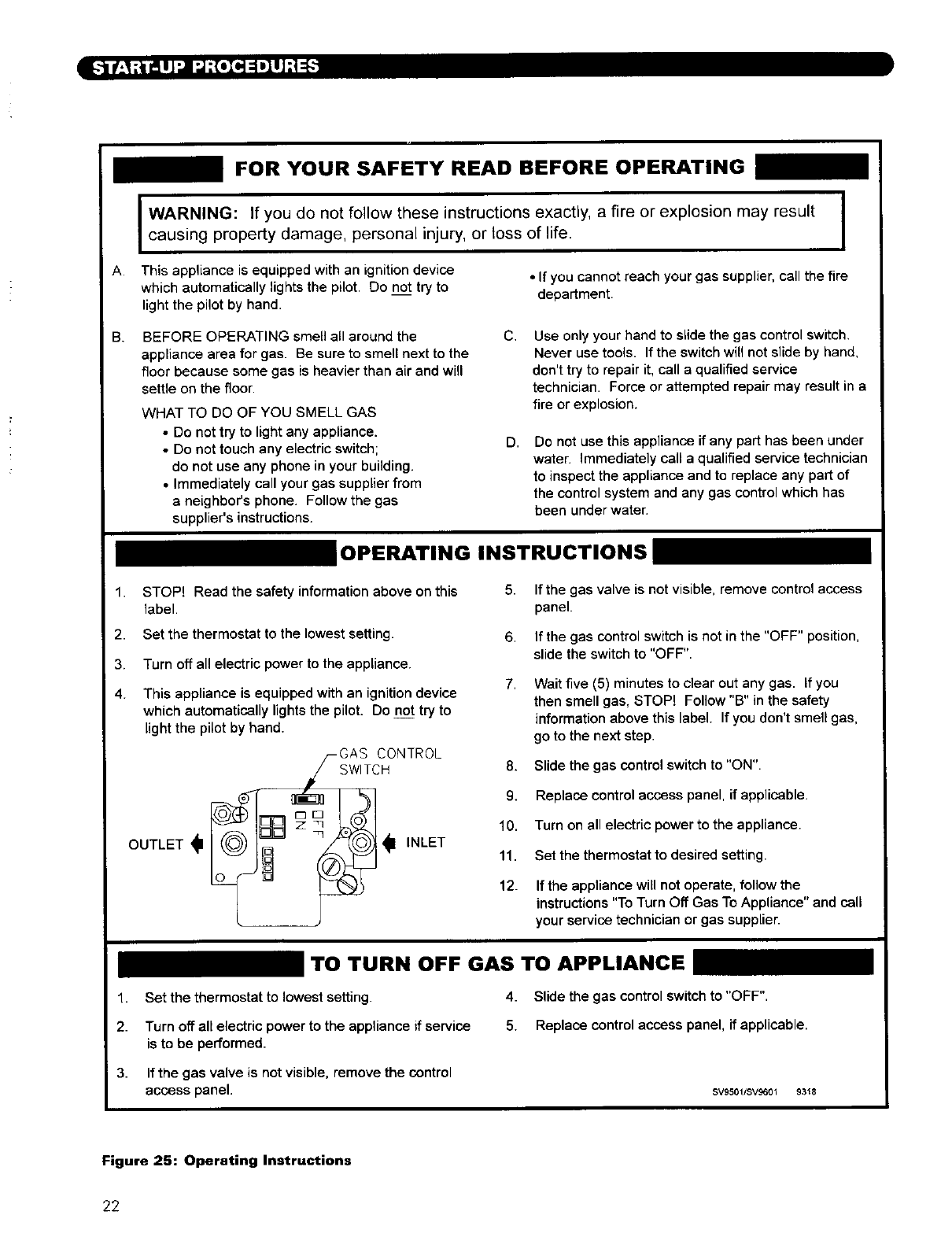
FOR YOUR SAFETY READ BEFORE OPERATING
I WARNING: If do follow these instructions a fire or explosion result I
you not exactly, may
causing property damage, personal injury, or toss of life. I
A. This appliance is equipped with an ignition device • If you cannot reach your gas supplier, call the fire
which automatically lights the pilot. Do not try to department.
light the pilot by hand.
g. BEFORE OPERATING smell all around the
appliance area for gas. Be sure to smell next to the
floor because some gas is heavier than air and will
settle on the floor.
WHAT TO DO OF YOU SMELL GAS
• Do not try to light any appliance.
• Do not touch any electric switch;
do not use any phone in your building.
• Immediately call your gas supplier from
a neighbor's phone. Follow the gas
supplier's instructions.
C, Use only your hand to slide the gas control switch,
Never use tools. If the switch will not slide by hand,
don't try to repair it, call a qualified service
technician. Force or attempted repair may result in a
fire or explosion.
D, Do not use this appliance if any part has been under
water. Immediately call a qualified service technician
to inspect the appliance and to replace any part of
the control system and any gas control which has
been under water,
_OPERATING INSTRUCTIONS
1. STOP! Read the safety information above on this
label.
5. If the gas valve is not visible, remove control access
panel.
2. Set the thermostat to the lowest setting.
3. Turn off all electric power to the appliance.
4. This appliance is equipped with an ignition device
which automatically lights the pilot. Do not try to
light the pilot by hand.
/--GAS CONTROL
SWITCH
6. If the gas control switch is not in the "OFF" position,
slide the switch to "OFF".
7. Wait five (5) minutes to clear out any gas. If you
then smell gas, STOP! Follow "B" in the safety
information above this label. If you don't smell gas,
go to the next step.
8. Slide the gas control switch to "ON".
9. Replace control access panel, if applicable.
10. Turn on all electric power to the appliance.
11. Set the thermostat to desired setting.
12. If the appliance will not operate, follow the
instructions "To Turn Off Gas To Appliance" and call
your service technician or gas supplier.
TO TURN OFF GAS TO APPLIANCE _
1. Set the thermostat to lowest setting. 4. Slide the gas control switch to "OFF".
2. Turn off all electric power to the appliance if service 5. Replace control access panel, if applicable.
is to be performed.
3. If the gas valve is not visible, remove the control
access panel. SV95011SV9601 9318
Figure 25: Operating Instructions
22
I[,-']t-'; • ,'_ B• "]
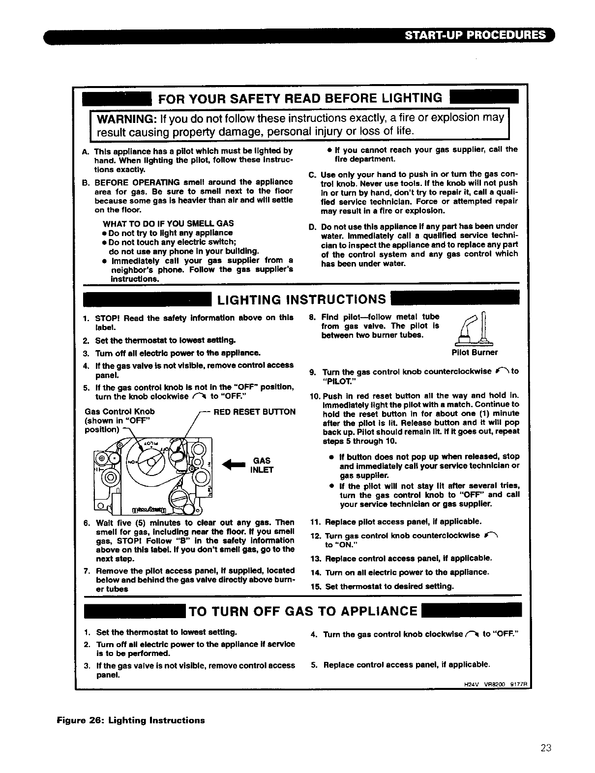
FOR YOUR SAFETY READ BEFORE LIGHTING
I
A. This •ppU•nce has a pilotwhich must be lighted by
hand. When lighting the pilot, follow these instruc-
tions exactly.
B. BEFORE OPERATING smell •round the appliance
area for gas. Be sure to smell next to the floor
because some gas is heavier than air and will settle
on the floor.
WARNING: If you do not follow these instructions exactly, a fire or explosion may
result causing property damage, personal injury or loss of life.
WHAT TO DO IF YOU SMELL GAS
• Do not try to light any appliance
• Do not touch any electric switch;
do not u•e any phone In your building.
• Immediately call your gas supplier from a
neighbor's phone. Follow the gas suppller's
instructions.
• If you cannot reach your gas supplier, call the
fire department.
C. Use only your hand to push in or turn the gas con-
trol knob. Never use tools. If the knob will not push
In or turn by hand, don't try to repair it, call a quali-
fied service technician. Force or attempted repair
may result in a fire or explosion.
D, Do not use this appliance if any pert has been under
water. Immediately cell a qualified service techni-
cian to inspect the appliance and to replace any part
of the control system and any gas control which
has been under water.
LIGHTING INSTRUCTIONS
1. STOP! Read the safety information above on this
label.
2. Set the thermostat to lowest setting.
3. Turn off •11 electric power to the appllence.
4. If the gas valve is not visible, remove control aceess
panel.
5. If the gas control knob is not in the "OFF" position,
turn the knob clockwise _to "OFF."
Gas Control Knob F'- RED RESET BUTTON
(shown in _OFF" /
position) -_ /
J*o_ id 41 A
. _1 INLET
6. Walt five (5) minutes to clear out any gas. Then
smell for gas, including near the floor. If you smell
gas, STOP; Follow "B" in the safety information
above on this label. If you don't smell gas, go to the
next step.
7. Remove the pilot access panel, if supplied, located
below and behind the gas valve directly above burn-
er tubes
8. Find pilot--follow metal tube F_
from gas valve. The pilot is
between two burner tubes.
Pilot Burner
9. Turn the gas control knob counterclockwise #"% to
"PILOT."
10. Push In red reset button all the way and hold in.
Immediately fight the pilot with • match. Continue to
hold the reset button in for •bout one (1) minute
after the pilot is lit. Release button and it will pop
back up. Pilot should remain llt. If it goes out, repeat
steps 5 through 10.
• If button does not pop up when released, stop
and immediately call your service tachnici•n or
gas supplier.
•If the pllet will not stay lit after several tries,
turn the gas control knob to "OFF" and cell
your service technician or gas supplier.
11. Replace pilot access panel, if applicable.
12. Turn gas control knob counterclockwise
to "ON."
13. Replace control access panel, if applicable.
14. Turn on all electric power to the •ppllance.
15. Set thermostat to desired setting.
_TO TURN OFF GAS TO APPLIANCE _
1. Set the thermostat to lowest setting.
2. Tum off all electric power to the appliance if service
is to be performed.
3. If the gas valve is not visible, remove control access
panel.
4. Turn the gas control knob clockwise (_ to "OFF."
5. Replace control access panel, if applicable.
H24V VR8200 9177R
Figure 26: Lighting Instructions
23
IsJ V-ll_i ilJ-*t iLhl_l i [*]; L:JII[*]t 11[€1r-"!.:1I_ K*PA
:]q '=*,[*]=_//;{*]n Im]:_'[*_;]lM/[*]_:
See Figure 16 in Section 6 (Electrical) for locations of
these devices.
I. FLAME ROLL-OUT SAFETY SHUT-OFF SWITCH
(FLAME ROLL OUT SWITCH) - A thermally
activated switch located between the first burner
from the left and the manifold bracket. The flame
roll-out safety shut-off switch will sense excessive
temperature caused by continued flame roll out and
shut down main burner gas. This is anon-recycling
switch that must be replaced once it has been
activated and the cause of the roll-out eliminated.
2.
3,
4.
VENT SAFETY SHUT-OFF SWITCH (SPILL
SWITCH) - A thermally activated, manually
resetable switch located in the draft hood relief
opening. If venting system becomes partially or
totally blocked, the vent safety shut-off switch will
sense excessive temperature caused by flue products
exiting the draft hood relief opening and shut down
main burner gas.
LIMIT (AQUASTAT) - A thermally activated,
manually adjustable switch located on the left side of
the boiler, towards the top and rear. The temperature
sensing element is placed in the supply and will shut
down main burner gas ifthe supply water exceeds
the preset temperature limit. This is a recycling
switch that will automatically reset when the supply
water falls below the preset temperature.
LOW WATER CUT-OFF (FOR GRAVITY SYSTEMS
OR HOT WATER BOILERS INSTALLED ABOVE
RADIATION LEVEL) -A level-sensing device (float
or probe) located in supply piping near the boiler. If
water level in the system drops below the control's
position, it will shut down main burner gas. The
control will automatically reset once the water level
rises above its position.
1.
I[*4:I=[NNh_(€4 :|lJ:t_J_:t IIL_I'._IJ
2,
3.
4.
Using the manometer setup installed in part 7A, set
manifold pressure as follows for various gases.
a. Natural Gas .......... 3.5" Water Column
b. LPGas ............ I0.0" Water Column
To adjust gas pressure, turn adjusting screw of gas .
pressure regulator counterclockwise to decrease
pressure, clockwise to increase pressure. Refer to
Figure 24 for location of gas pressure regulator.
Replace the cap screw when adjustment is complete.
In no case should the final manifold pressure vary
more than ±0.3 inches water column from the
above specified pressures. Any necessary major
changes in the flow should be made by changing the
size of the burner orifice spuds.
When adjustment is complete, turn off boiler, gas
flow and electricity to boiler. Remove manometer
connection from valve and plug tapping with plug
provided. Turn utilities back on and resume
checkout.
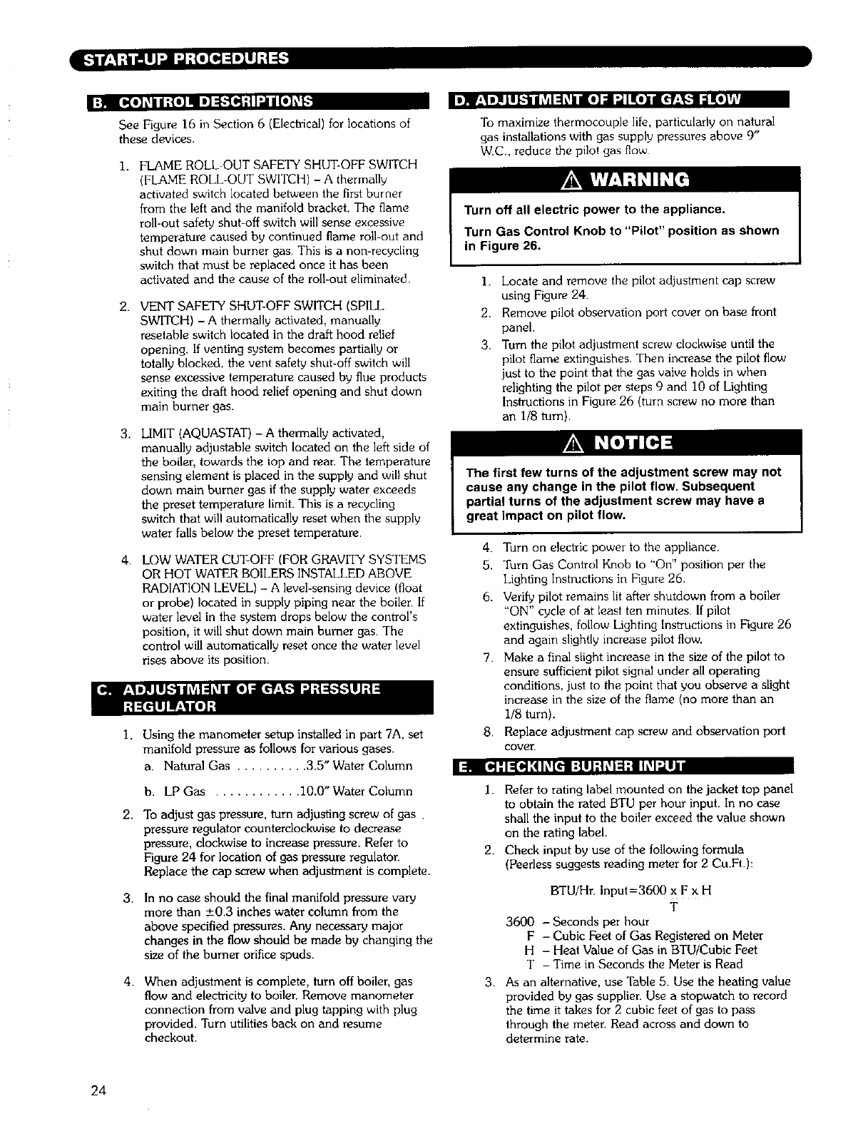
To maximize thermocouple life, particularly on natural
gas installations with gas supply pressures above 9"
W.C.. reduce the pilot gas flow
Turn off all electric power to the appliance.
Turn Gas Control Knob to "Pilot" position as shown
in Figure 26.
].
2.
3.
Locate and remove the pilot adjustment cap screw
using Figure 24.
Remove pilot observation port cover on base front
panel.
Turn the pilot adjustment screw clockwise until the
pilot flame extinguishes. Then increase the pilot flow
just to the point that the gas valve holds in when
relighting the pilot per steps 9 and 10 of Lighting
Instructions in Figure 26 (turn screw no more than
an i/8 turn).
The first few turns of the adjustment screw may not
cause any change in the pilot flow, Subsequent
partial turns of the adjustment screw may have a
great impact on pilot flow.
4. Turn on electric power to the appliance.
5. Turn Gas Control Knob to "On" position per the
Lighting Instructions in Figure 26.
6. Verify pilot remains lit after shutdown from a boiler
"ON" cycle of at least ten minutes. If pilot
extinguishes, follow Lighting Instructions in Figure 26
and again slightly increase pilot flow.
7. Make a final slight increase in the size of the pilot to
ensure sufficient pilot signal under all operating
conditions, just to the point that you observe a slight
increase in the size of the flame (no more than an
I/8 turn).
8. Replace adjustment cap screw and observation port
cover.
I. Refer to rating label mounted on the jacket top panel
to obtain the rated BTU per hour input. In no case
shall the input to the boiler exceed the value shown
on the rating label.
2. Check input by use of the following formula
(Peerless suggests reading meter for 2 Cu.Ft.):
3.
BTU/Hr. Input=3600 x F x H
T
3600 -Seconds per hour
F - Cubic Feet of Gas Registered on Meter
H - Heat Value of Gas in BTU/Cubic Feet
T - Time in Seconds the Meter is Read
As an alternative, use Table 5. Use the heating value
provided by gas supplier. Use a stopwatch to record
the time it takes for 2 cubic feet of gas to pass
through the meter. Read across and down to
determine rate.
24
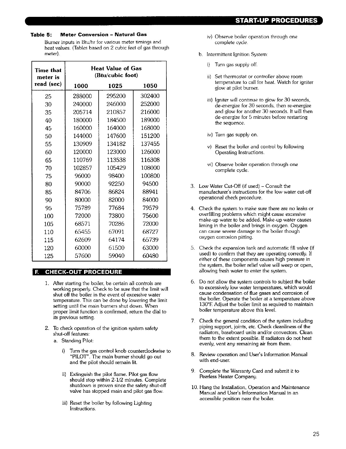
Table 5: Meter Conversion - Natural Gas
Burner inputs in Btu/hr for various meter timings and
heat values. (Tables based on 2 cubic feet of gas through
meter).
Time that Heat Value of Gas
meter is (Btu/cubic foot)
read (sec)
25
30
35
40
45
50
55
60
65
70
75
80
85
90
95
I00
105
110
115
120
125
1000
288000
240000
205714
180000
160000
144000
130909
120000
110769
102857
96000
90000
84706
80000
75789
72000
68571
65455
62609
60000
57600
1025 1050
295200 302400
246000 252000
210857 216000
184500 189000
164000 168000
147600 151200
134182 137455
123000 126000
113538 116308
105429 108000
98400 100800
92250 94500
86824 88941
82000 84000
77684 79579
73800 75600
70286 72000
67091 68727
64174 65739
61500 63000
59040 60480
I;;I [O4:l=(O4[_eleJld :J;{ole]=lmlgl;|
I. After starting the boiler, be certain all controls are
working properly. Check to be sure that the limit will
shut off the boiler in the event of excessive water
temperature. This can be done by lowering the limit
setting until the main burners shut down. When
proper limit function is confirmed, return the dial to
its previous setting.
2. To check operation of the ignition system safety
shut-off features:
a. Standing Pilot:
i) Turn the gas control knob counterclockwise to
"PILOT". The main burner should go out
and the pilot should remain lit.
ii) Extinguish the pilot flame. Pilot gas flow
should stop within 2-I/2 minutes. Complete
shutdown is proven since the safety shut-off
valve has stopped main and pilot gas flow.
iii) Reset the boiler by following Lighting
Instructions.
3.
4.
5.
6.
7.
8.
9.
i0.
iv) Observe boiler operation through one
complete cycle
b. Intermittent Ignition System:
i) Turn gas supply off
it) Set thermostat or controller above room
temperature to call for heat. Watch for igniter
glow at pilot burner.
iii) Igniter will continue to glow for 30 seconds,
de-energize for 30 seconds, then re-energize
and glow for another 30 seconds. It will then
de-energize for 5 minutes before restarting
the sequence.
iv) Turn gas supply on.
v) Reset the boiler and conlrol by following
Operating Instructions.
vi) Observe boiler operation through one
complete cycle.
Low Water Cut-Off (if used) -Consult the
manufacturer's instructions for the low water cut-off
operational check procedure.
Check the system to make sure there are no leaks or
overfilling problems which might cause excessive
make-up water to be added. Make-up water causes
liming in the boiler and brings in oxygen. Oxygen
can cause severe damage to the boiler though
oxygen corrosion pitting.
Check the expansion tank and automatic fill valve (if
used) to confirm that they are operating con-ectly. If
either of these components causes high pressure in
the system, the boiler relief valve will weep or open,
allowing fresh water to enter the system.
Do not allow the system controls to subject the boiler
to excessively low water temperatures, which would
cause condensation of flue gases and corrosion of
the boiler. Operate the boiler at a temperature above
130°E Adjust the boiler limit as required to maintain
boiler temperature above this level.
Check the general condition of the system including
piping support, joints, etc. Check cleanliness of the
radiators, baseboard units and!or convectors. Clean
them to the extent possible. If radiators do not heat
evenly, vent any remaining air from them.
Review operation and User's Information Manual
with end-user.
Complete the Warranty Card and submit it to
Peerless Heater Company.
Hang the Installation, Operation and Maintenance
Manual and User's Information Manual in an
accessible position near the boiler.
25
In the event of a shut-down caused by a pLlot outage
actLon of the blocked vent shut-ott sw_tch or flame Toll-
out safety shut-off swltch effechng a shin-down of the
mallq burners
a Refer to the Lighting, Operating Instructions Ln
Figures 25 and 26 to properly turn oft the gas to the
boiler
b Turn off all electric power to the boder
c Call a qualified heatlng servlce orgamzahon or Local
gas company and have the cause of the shut-down
mveshgated and corrected
d Refer to L_ghtlng'Operatmg Instruchons to
re start bo_ler
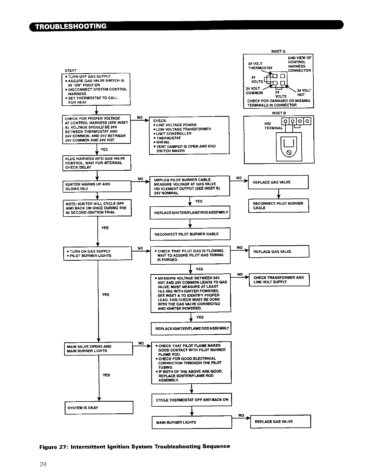
:! I |'{o]lJ :| i :_'t : [oil) i h,_[_ [_lll I I] :_
Use Table 6 to assist m determining causes and
prowdmg corrective actions to boiler problems Refer
also to Figure 27 to _oubleshoot the [merm_ttent lgnLtLOn
System Control These guLdes must be used only by
quahhed serwce techntoans These mdwlduals must
tollow all apphcable codes and _egulat,ons ,n repair of
any bo,le_ problems
When servicing or replacing items that communicate
with the bonier water, be certain that"
•There is no pressure on the boLler
•The boiler us not hot.
•The power is off.
When servicing the gas valve or pilot, be certain that:
•The gas is off.
•The electricity is off.
Do not use this appliance if any part has been under
water. Improper or dangerous operation may result.
Immedmtely call a qualified service technician to
inspect the bonier and to replace any part of the
control system and any gas control which has been
under water.
Label all wires prior to disconnection when servicing
controls. Wiring errors can cause improper and
dangerous operation. Verify proper operation after
servicing.
Should overheating occur or the gas supply fail to
shut off, do not turn off or disconnect the electrical
supply to the pump.This may aggravate the problem
and increase the likelihood of boiler damage. Instead,
shut off the gas supply at a location external to the
appliance.
26
Inj ;[.luJ :_! _; [oD_ ni1_L_
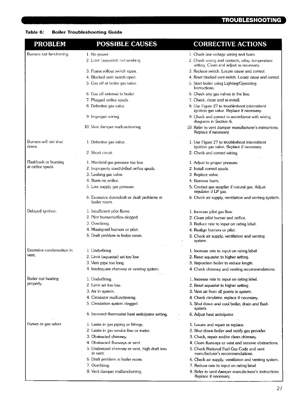
Table 6: Boiler Troubleshooting Guide
Burners not functioning ] No power
2. Limit (aquastat) not working
3. Flame rollout switch open
4. Blocked vent switch open
.5 Gas off at boiler gas valve
6 Gas off external to boiler
7 Plugged orifice spuds
8. Defective gas valve
9 Improper wiring
10 Vont damper malfunctioning
Burners will not shut
down
Flashback or burning
at orifice spuds.
Delayed ignition.
1. Defective gas valve.
2 Short circuit
I. Manifold gas pressure too low
2. Improperly sized/drilled orifice spuds.
3. Leaking gas valve
4 Burrs on orifice.
5Low supply gas pressure.
6 Excessive downdraft or draft problems in
boiler room
l Insufficient pilot flame
2. Pilot burner/orifice clogged.
30verfiring.
4 Misaligned burners or pilot.
5 Draft problem in boiler room.
Excessive condensation in
vent.
Boiler not heating
properly.
Fumes or gas odors
I. Underfiring
2. Limit (aquastat) set too low.
3 Vent pipe too long.
4. Inadequate chimney or venting system.
1. Underflring
2 Limit set too low.
3. Air in system.
4. Circulator malfunctioning.
5 Circulation system clogged.
6. Incorred thermostat heat anticipator setting.
I. Leaks in gas piping or fittings.
2. Leaks in gas service line or meter
3. Obstructed chimney.
40bslructed flueways or vent.
5 Undersized chimney or vent, high draft loss
in vent
6 Draft problem in boiler room.
7. Overfiring.
8 Vent damper malfunctioning.
I Check line voltage wiring and fuses.
2 Check wiring and contacts, relay, temperature
setting. Clean and adjust as necessary
3. Replace switch Locate cause and correct.
4. Reset blocked vent switch. Locate cause and correct.
5 Start boiler using Lighting/Operating
Instructions.
6 Check any gas valves in the line.
7 Check, clean and re-install.
8 Use Figure 27 to troubleshoot intermittent
ignition gas valve. Replace if necessary.
9. Check and correct in accordance with wiring
diagrams in Section 6.
I0 Refer to vent damper manufacturer's instructions.
Replace if necessary.
1. Use Figure 27 to troubleshoot intermittent
ignition gas valve. Replace if necessary.
2. Check and correct wiring.
I. Adjust to proper pressure.
2. Install correct spuds.
3 Replace valve.
4. Remove burrs.
5. Contact gas supplier if natural gas. Adjust
regulator if LP gas.
6 Check air supply, ventilation and venting system.
1. Increase pilot gas flow,
2. Clean pilot burner and orifice.
3. Reduce rate to input on rating label.
4. Realign burners or pilot.
5. Check air supply, ventilation and venting
system.
I. Increase rate to input on rating label.
2. Reset aquastat to higher setting.
3. Reposition boiler to reduce length.
4. Check chimney and venting recommendations.
1. Increase rate to input on rating label.
2. Reset aquastat to higher setting.
3. Vent air from all points in system.
4. Check circulator, replace if necessa W.
5. Shut down and cool boiler, drain and flush
system.
6. Adjust heat anticipator.
I. Locate and repair or replace.
2. Shut down boiler and notify gas provider.
3. Check, repair and/or clean chimney.
4. Clean fiueways or vent and remove obstructions.
5. Check National Fuel Gas Code and vent
manufacturer's recommendations.
6. Check air supply, ventilation and venting system.
7. Reduce rate to input on rating label.
8. Refer to vent damper manufacturer's instructions.
Replace if necessary.
27
START
I• TURN OFF GAS SUPPLY
•ASSURE GAS VALVE SWITCH IS
iN "ON" POSITION
• DISCONNECT SYSTEM CONTROL
HARNESS
•SET THERMOSTAT TO CALL
FOR HEAT
l
CHECK FOR PROPER VOLTAGE NI NO _[
AT CONTROL HARNESS (SEE INSET I1
A). VOLTAGE SHOULD BE 24V
BETWEEN THERMOSTAT AND
24V COMMON, AND 24V BETWEEN
24V COMMON AND 24V HOT.
YES
ii i: ',Fo L
l
I, .:W,:oW RMSUPANDQ
+
NOTE: iGNITER WILL CYCLE OFF
AND BACK ON ONCE GURING THE
90 SECOND IGNITION TRIAL
IYES
•TURN ON GAS SUPPLY _=_
• PILOT BURNER IJGHTS
YES
r
I MAIN VALVE OPENS AND
MAIN BURNER LIGHTS
YES
CHECK:
•LINE VOLTAGE POWER
•LOW VOLTAGE TRANSFORMER
• LIMIT CONTROLLER
•THERMOSTAT
•WIRING
•VENT DAMPER IS OPEN AND END
SWITCH MAKES
INSET A
UNPLUG PILOT BURNER CABLE.
MEASURE VOLTAGE AT GAS VALVE I '
HSI ELEMENT OUTPUT (SEE INSET B)
24V NOMINAL
I YEs
IREP CE'GN'TE MEROOA--OLYI
I RECONNECT PILOT BURNER CABLE I
END VIEW OF
24 VOLT CONTROL
THERMOSTAT HARNESS
CONNECTOR
VOLTS
24 VOLT 24 VOLT
COMMO VOLTS HOT
CHECK FOR DAMAGED OR MISSING
TERMINALS IN CONNECTOR
INSET B
REPLACE GAS VALVE I
I
I RECONNECTPILOTBURNER I
CABLE
•CHECK THAT PILOT GAS IS FLOWING. REPLACE GAS VALVE
WAIT TO ASSURE PILOT GAS TUBING
IS PURGED,
YES ,NO,
•MEASURE VOLTAGE BETWEEN 24V _CHECK TRANSFORMER AND
HOT AND 24V COMMON LEADS TO GAS I i LINE VOLT SUPPLY
VALVE. MUST MEASURE AT LEAST
19.5 VAC WITH IGNITER POWERED.
SEE INSET A TO IDENTIFY PROPER
LEAD. THIS CHECK MUST BE DONE
WITH THE GAS VALVE CONNECTED
AND IGNITER POWERED,
YES
I REPLACE IG NITER/FLAM E ROD ASSIEMBLY ]
CYCLE THERMOSTAT OFF AND BACK ON I
SYSTEM IS OKAY
I MAIN BURNER LIGHTS _1 REPLACE GAS VALVE
• CHECK THAT PILOT FLAME MAKES
GOOD CONTACT WITH PILOT BURNER
FLAME ROD.
•CHECK FOR GOOD ELECTRICAL
CONNECTION THROUGH THE PILOT
TUBING
•IF BOTH OF THE ABOVE ARE GOOO,
REPLACE IGNITER/FLAME ROO
ASSEMBLY.
I I
I
I
Figure 27: Intermittent Ignition System Troubleshooting Sequence
28
h',!_,!1_i i 4 _<'_!_,l7[.I:
9. MAINTENANce.
l-*! [€l _L'I_IP.t.
1 Disconnect this boiler from the gas supply piping
durung any pressure testing of the gas system
2 Check pipes adjacent to cold walls or in unheated
spaces Insulate and tape them Lfnecessary to be
sure they can t freeze up Keeping the water moving
at all times will reduce the likelihood of freezing See
Section 3 for antifreeze instnictions
3 If there is considelable foreign matter in the boiler
water the boiler should be shut down and allowed to
cool then drained and thoroughly flushed out Use
the dram valve at the bottom of the return
connect,on to drain the boiler Pipe the dram cock to
a suitable drain or containment dewce _f antifreeze is
used Flush the system to remove remaining matter
If there is evidence that hard scale has formed on the
internal surfaces, the boiler should be cleaned by
chemical means as prescribed by a quahhed water
treatment specLal_st
There must not be signs of continuous wetness at the
chimney If s_gns of continuous wetness are
observed, a qual_hed service agency must be
consulted to modify the vent confLguratLon to prevent
the tormatlon of condensate
i:II Ill7,_!ll'lllVi_li/ll :loll!!llh"lll--'l"
Daily boiler observatLon can be performed by the owner
If any potential problems are found, a quahfLed installer
or service techmc_an,'agency must be notffued
Remove any combustible materials, gasohne and
other flammable hqulds and substances that generate
flammable vapors from the area where the bouler LS
contained Make certain that the boiler area has
ample air for combustion and venhlation and that
there are no obstructions to the free flow of air to
and from the boiler
2 Observe general boiler conditions (unusual noises,
vibrations, etc )
Observe operatLng temperature and pressure on the
combmatlon gauge located on the left side of the
boiler Boiler pressure should never be higher than
5 psl below the rating shown on the safety rehef
valve {25 ps_g max,mum for a 30 psLg rating, 45 pslg
maximum for a 50 pslg rating) The valve rating can
be found on the top of the safety relief valve (see
Figure 5 for location of the safety relief valve) Boiler
temperature should never be higher than 250 GF
4 Check for water leaks in boiler and system piping
5 Smell around the apphance alea for gas It you smell
gas. follow the procedure listed m the
LLghtJng, Operatlng Instructions m Section 7
lllhll I 1 [! li'illrlll / iI I :[o] I I 11tl li'lllll-'t :
I Flush float-type low-water cut-off (if used) to remove
sedLment from the float bowl as stated m the
manufacturer's instructions
Uill_'5 [oli_i/ l lii'llli,_i / I: i :io]I I 1 :g h,'_lil..'ti
1 Check boiler room floor dlalns fol proper
functioning
2Check function of the safety relief valve (monthly
unless speofled otherwise by manufacturer) by
performung the follo_,,ungtest
aCheck valve pLpmg to determine that ,t is
properly installed and supported
b Check boiler operating temperature and pressure
c Lift the ti'y level on the safety relief valve to the
full open position and hold Ltfor at least five
seconds or until clean water LSdischarged
Release the try lever and allow the valve to close
If the valve leaks, operate the lever two or thlee
times to clear the valve seat of foreign matter It
may take some t_me to deteu'mne _tthe valve has
shut completely
eIf the valve continues to leak. it must be replaced
before the boiler is returned to operation
f Check that operating pressure and temperature
have returned to normal
g Check again to confirm that valve has closed
completely and is not leaking
3 Test low-water cut-off (if used) as descnbed by the
manufacturer
4 Test limit as described in Section 7E "Check-Out
Procedure "
5 Test function of gas safety shut-off features as
described by gas valve and ugnution control
manufacturer
6 Cycle the boiler at least once and check operation of
the vent damper
29
When servicing or replacing components, be
absolutely certain that the following conditions are
met:
• Water, gas and electricity are off.
• The boiler is at room temperature.
•There is no pressure in the boiler.
OUTE ON i
// [)ARK BL JL //_\
IN CC' OR , /
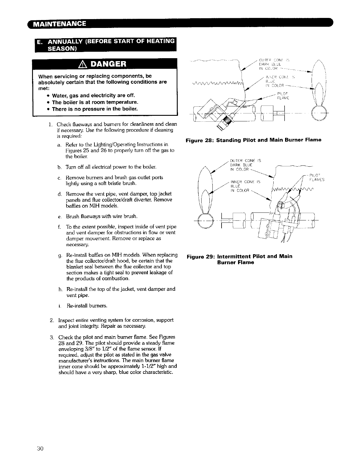
1. Check flueways and burners for cleanliness and dean
if necessary. Use the following procedure if cleaning
is required:
a. Refer to the Lightin_Operating Instructions in
Figures 25 and 26 to properly turn off the gas to
the boiler.
b. Turn off all electrical power to the boiler.
c. Remove burners and brush gas outlet ports
lightly using a soft bristle brush.
d. Remove the vent pipe, vent damper, top jacket
panels and flue collector/draft diverter. Remove
baffles on MIH models.
e. Brush flueways with wire brush.
To the extent possible, inspect inside of vent pipe
and vent damper for obstructions in flow or vent
damper movement. Remove or replace as
necessa[v.
g. Re-install baffles on MIH models. When replacing
the flue collector/draft hood, be certain that the
blanket seal between the flue collector and top
section makes a tight seal to prevent leakage of
the products of combustion.
h. Re-install the top of the jacket, vent damper and
vent pipe.
i. Re-install burners.
Figure 28: Standing Pilot and Main Burner Flame
INNER CONE IS
BLUE
IN COLOR
FLA_EB
Figure 29: Intermittent Pilot and Main
Burner Flame
2.
3.
Inspect entire venting system for corrosion, support
and joint integrity. Repair as necessary.
Check the pilot and main burner flame. See Figures
28 and 29. The pilot should provide a steady flame
enveloping 3/8" to i/2" of the flame sensor. If
required, adjust the pilot as stated in the gas valve
manufacturer's instructions. The main burner flame
inner cone should be approximately 1-1/2" high and
should have a very sharp, blue color characteristic.
3O
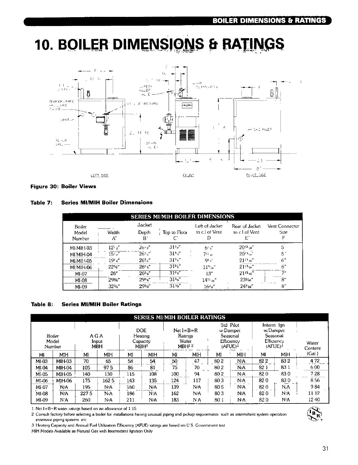
10. BOILER DIMENSIONS 8RA !N GS
II I,
_,111 ,
TEtd_"E_ - [iIPE
b- _ I_IFE l .
FL ,L_=
LIrL
I
I.
FLLIEF
Figure 30: Boiler Views
irllt_ ii
I
Table 7: Series MI/MIH Boiler Dimensions
Boiler
.ode] / Width
Number IA"
111:i I1i,.I1_Ia_ I I: I :[l] I I1_1:i 1]I_ I =1_._1[l]_p
I
Jacket Left of Jacket Rear of Jacket Vent Connector
i
Depth I Top _o F]oo_ to c ]ot Vent to c ] of Vent Size
B' C' D E" F
ML,MIH-03 121 -/'
MI$4IH-04 15%"
MbMIH-05 19_4"
M['MIH-06 22%"
MI-07 26"
MI-08 29%"
MI-09 32_"
20_ " 31%" 61 ," 2013Le" 5
26%" 31%" 7 n,_ 20_,,J 5'
26%" 31%" 9_ '2Ill,#" 6"
26%" _ 31%" 11%." 21_'_ " 6"
26%" 31_ " 13" 21_q_ " ;T'
29%" 31%" 14 u =_" 235h_" I8-
29_,_,, 31%- ; 16%- 24%e- 8..
I
Table 8: Series MI/MIH Boiler Ratings
DOE
Boiler A GA Heaung
Model Input Capacity Water Efficiency EMc[enc_ Water
Number MBH MBH3 MBHI2 (AFUE)3 I (AFUE)3 Content
.l IMIH I.i. Mi I ,H :Mill, MIH I (Gal)
M1-04 MIH-04 I05 1 975 86 i _l_ 75 1 70 802 I N/A _821 1 831 :600
M 05 MH-05 140 130 _ 115 I 108 i_4 94 ° 802 1 N/A 820 830 728
MI-06' MIH-06 175 11625 _ 143 I 135_ 124 _ 117 803 _ N/A_20 830 856
MJ-07_ N/A _ _95 11 N/A | 160 1_]39, N/A 805 t N,A I820 1 N,AI 98_
MI-08 I N/A 2275 N,,A / 186 / N'A I 162 N/A 803 N/A [ 82o / N'A _ _ ]2
MI-09 N'A 260 N,A I 211 INIA ;183 IN A 80 1 I N_A 82 0 N,A 12 40
Net I=B=R waterratingsbased on an allowance of 1 15 L_I_I_!
ConsulI factory before s_]e_lng a boiler _or installations having unusual piping and pickup requlrement_ such as intermittent system operahon
e_.[enslv_ piping s_s[ems etc
3Heatln9 Capacityand Annual FuelUbl_anon Efficiency (AFUE) rabngsarebasedon USGovernmenttest
N[H ModelsAvailable asNatural Gas wn[hInlerm_ttenlIgmhonOnly
31
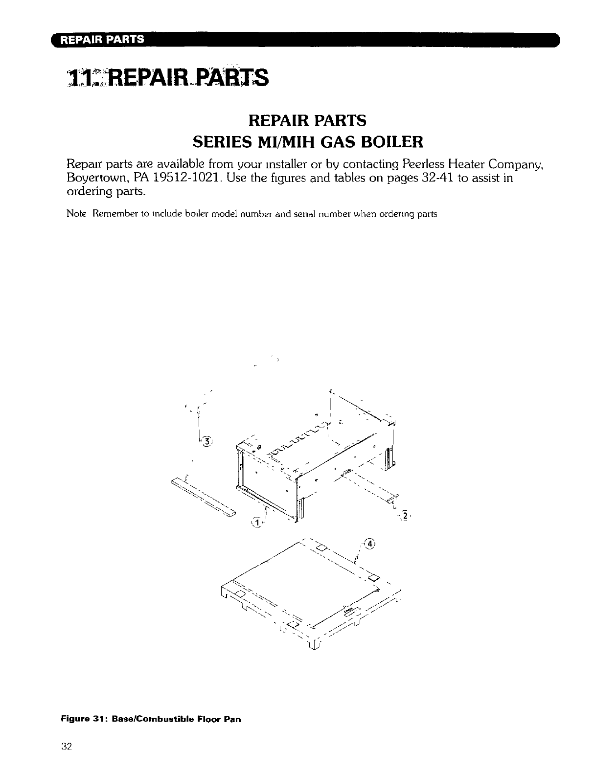
]3 ;;_ EPAIR_PABTS
REPAIR PARTS
SERIES MI/MIH GAS BOILER
Repair parts are available from your installer or by contacting Peerless Heater Company,
Boyertown, PA 19512-1021. Use the figures and tables on pages 32-41 to assist in
ordering parts.
Note Remember to include boiler model number and serial number when ordenng parts
3
Figure 31: Base/Combustible Floor Pan
32

Table 9: Base/Combustible Floor Pan
]Base Assembly
2 Observation Cover Door
3 Base Blanket Seal
4 Combustible Floor Pan Assembly
Specify length
91518
51771
50867
90700
91883 91897
51771 51771
50867 50867
90701 90702
91909 93561
51771 51771
50867 50867
90703 90704
93573 81036
51771 81771
50867 50867
90705 90706
33
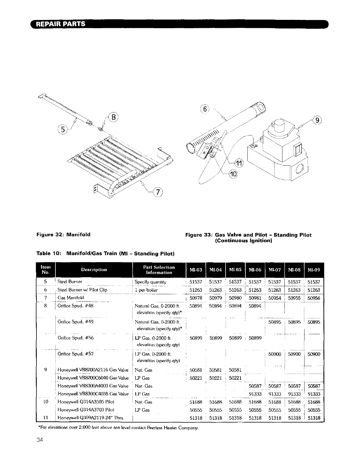
,,6) _\\
Figure 32: Manifold
Table 10: Manifold/Gas Train (MI - Standing Pilot)
Figure 33: Gas Valve and Pilot - Standing Pilot
(Continuous Ignition)
Steel Burner ! Specify quantity
• t
6 _Steel Burner w/Pilot Clip I per boiler 51263 51263
i _as Manifold -" -- i 50978 "50979
I
8 _'_i Orifice Spud_48 i Natural Gas,O 2000 ft, : 50894 50894
o,ficespuZ_49
I
Orifice Spud, #56
_Or_f_ceSpud,#57
i
i elevation (specify qty)*
Natural Gas, 0-2000 ft.
elevation (specify q_)*
i LP Gasl 0;2000 _, 50899 50899 50899 : 50899
elevation (specify qty)
i LP Gas, 0-2000 ft.
i
! elevation (specify qty)
i
9Honeywell VR8200A2116 Gas Va]ve [Nat. Gas
Honeywe!! VR820(_6040 Gas Valve LP Gas
] Honeywell VR8300A4003 Gas Valve Nat Gas
I Honeywell VR8300C4035 Gas Valve i LP Gas
I0 Honeywell Q314A3505 Pilot I Nat. Gas
HoneYwell Q314A3703 pi!ot . LP Gas
11 IHoneywellQ309A2119-24" Thin I
51263 51263 51263
50980 50981 0954 50955
50894 50894
i 50895 50895 50895
I
i 50900 50900_ s0900
!
50581 50581
5022ii50 21';0s87! 0587
91333 91333 91333 ' 91333
51688 51688 51688 51688 51688 51688
•;
50555 50555 50555 i 50555
51318 51318 51318 i 51318
50581
50221
51688
50555 50555 50555
51318 ! 51318 ! 51318
*For elevations over 2,000 feet above sea level contact Peerless Heater Company.
34
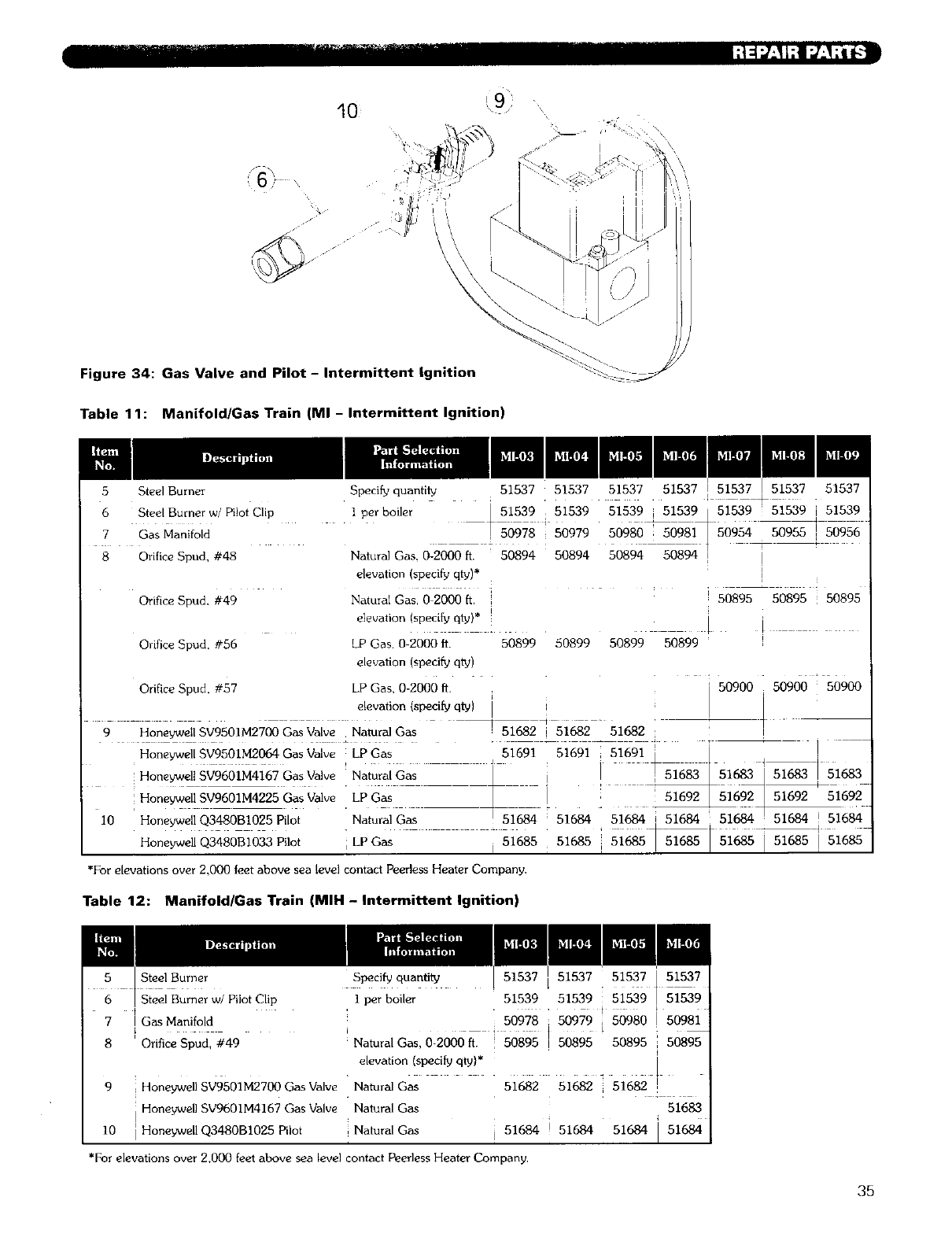
Figure 34: Gas Valve and Pilot -Intermittent ignition
Table 11: Manifold/Gas Train (MI - Intermittent Ignition)
5 Steel Burner
6 Steel Burner w/Pilot Clip
7 Gas Manifold
8 Orifice Spud, #48
Speci_ quanfl_ 51537 51537 51537 51537 [ 51537 51537
lperbo er i 51539i5153951539i51539 51539!51539i 51539
:s097950980 s09 , 50956
Natural Gas, 0-2000 fi. 50894 50894 50894 50894 I
elevation (specify qty)*
Orifice Spud, #49 Natural Gas, 0 2000 ft. , i 50895--50895 50895
i
elevation (specify qty)* [ [
Orifice Spud, #56 LP Gas. 0-2000 ft. 50899 50899 50899 50899
elevation (specify qty)
Orifice Spud, #57 LP Gas, 0-2000 It. 50900 50900 50900
elevation (specify q_} i
9 Honeywell SV9501M2700 Gas Valve Natural Gas ! 51682 i 51682 51682 I
Honeywell SV9501M2064 Gas Valve LP Gas J 51691 51691 i 51691 i [ ]
Honeywell SV9601M4167 Gas Valve i Natura! Gas _ ] 1
Honeywell SV9601M4225 Gas Valve• Lp Gas _ L : _6!!_692
I0 Honeywell Q3480B1025 Pilot Natural Gas ! 5168451684 51_ ;51684 516_ 51684 !51684
Honeywell Q3480B1033 Pilot i LPGas I 51685 81685 51685 51685 51685 ] 51685 ] 51685
*For elevations over 2,000 feet above sea level contact Peerless Heater Company•
Table 12: Manifold/Gas Train (MIH - intermittent ignition)
7
8
9
I0
Steel Burner
Steel Burner w/Pilot Clip
Gas Manifold
Orifice Spud, #49
Honeywell SV9501M2700 Gas Valve Natural Gas
Honeywell SV9601M4167 Gas Valve Natural Gas
Honeywell Q3480BI025 Pilot Natural Gas
Specify quantily 51537 51537
1 per boiler 51539 51539 51539
5097850979 ] 50980 [ S098i
Natural Gas, 0-2000 fi. 50895 I 50895 50895 i 50895
elevation (specify qty)* i
51682 51682 51682 !
51683
,51684 i 51684 51684 ] 51684
*For elevations over 2,000 feet above sea level contact Peerless Heater Company,
35
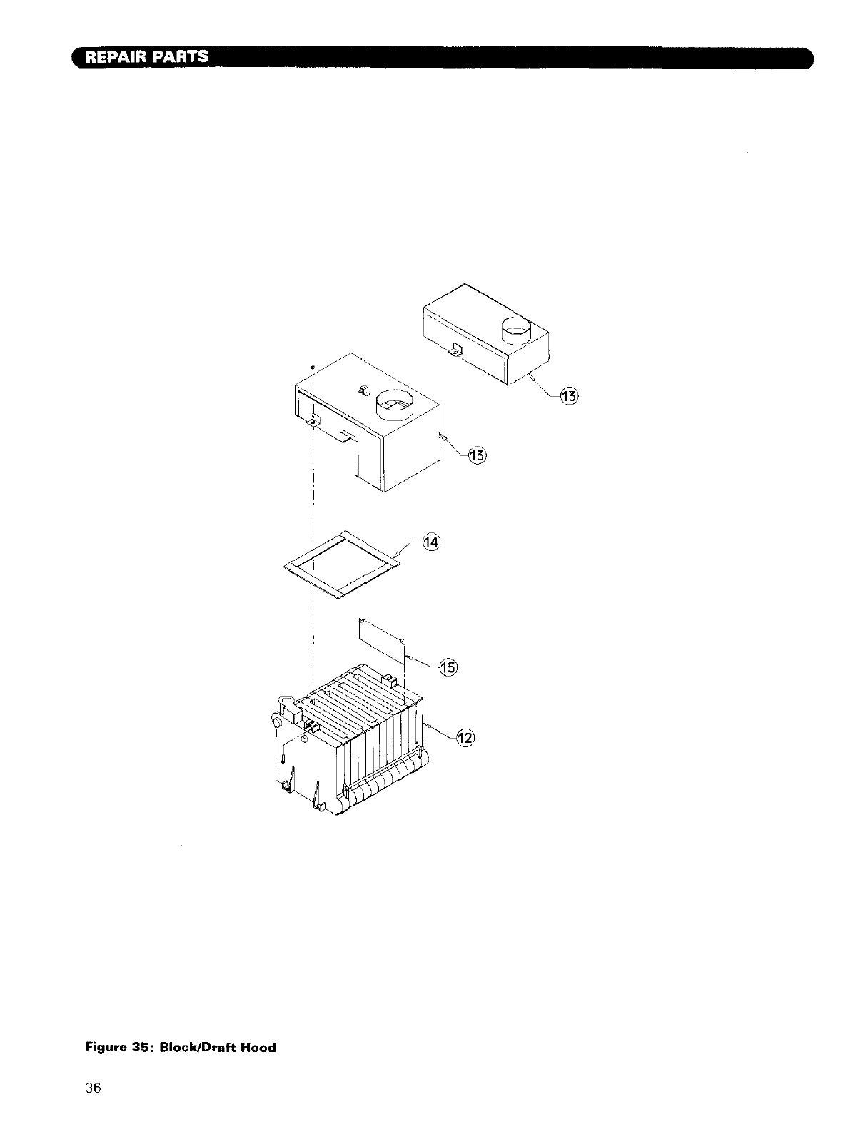
Figure 35: Block/Draft Hood
36
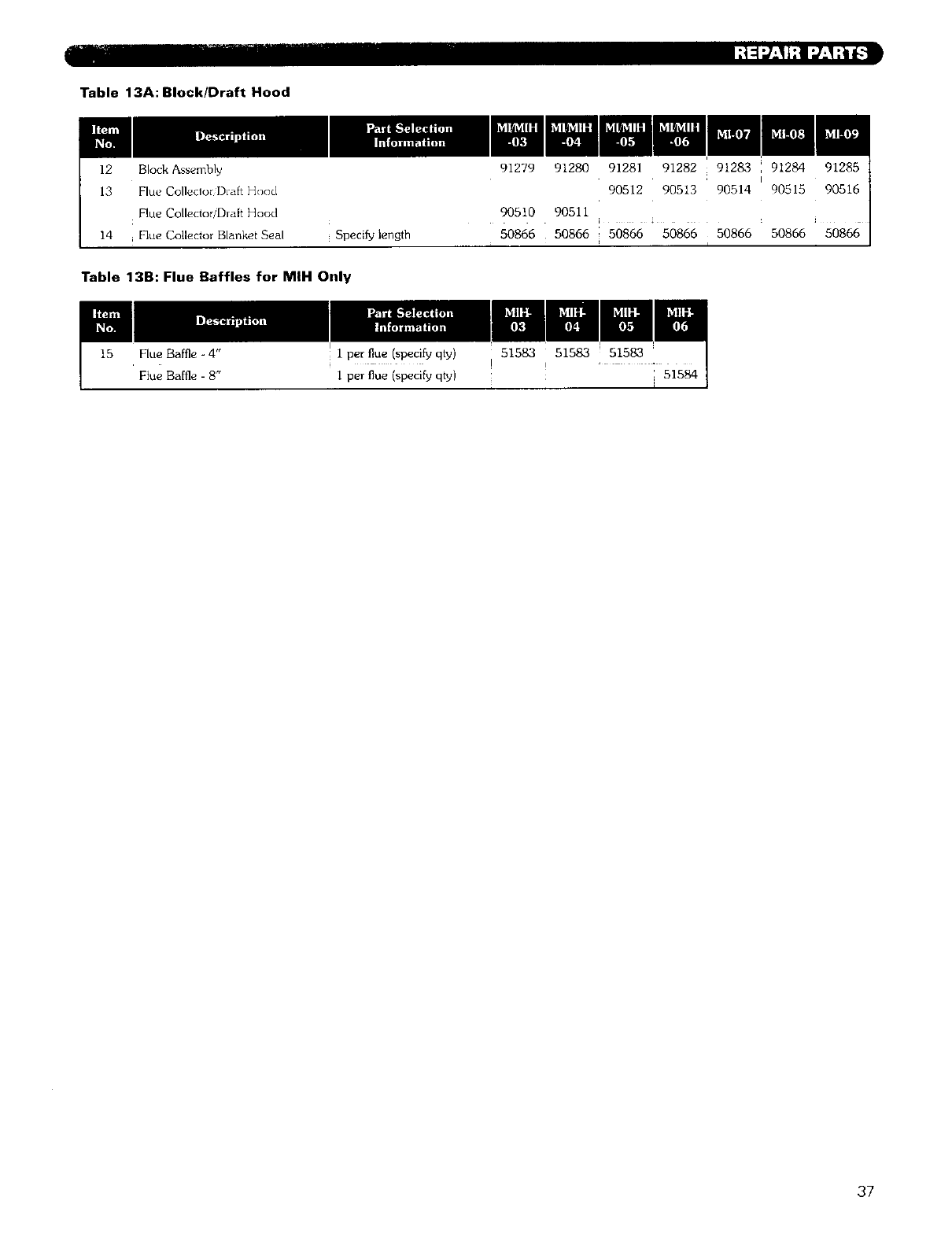
Table 13A: Block/Draft Hood
12 Block Assembly
13 Flue CollecloriDraft Hood
Flue CollectorlDraft Hood
14 _ Flue Collector Blanket Seal Specify length
Table 13B: Flue Baffles for MIH Only
50866
91280
90511
50866
15 Flue Baffle - 4"
Flue Baffle - 8"
I1 per flue (specify qty)
1 per flue (specify qty)
51583
I
37
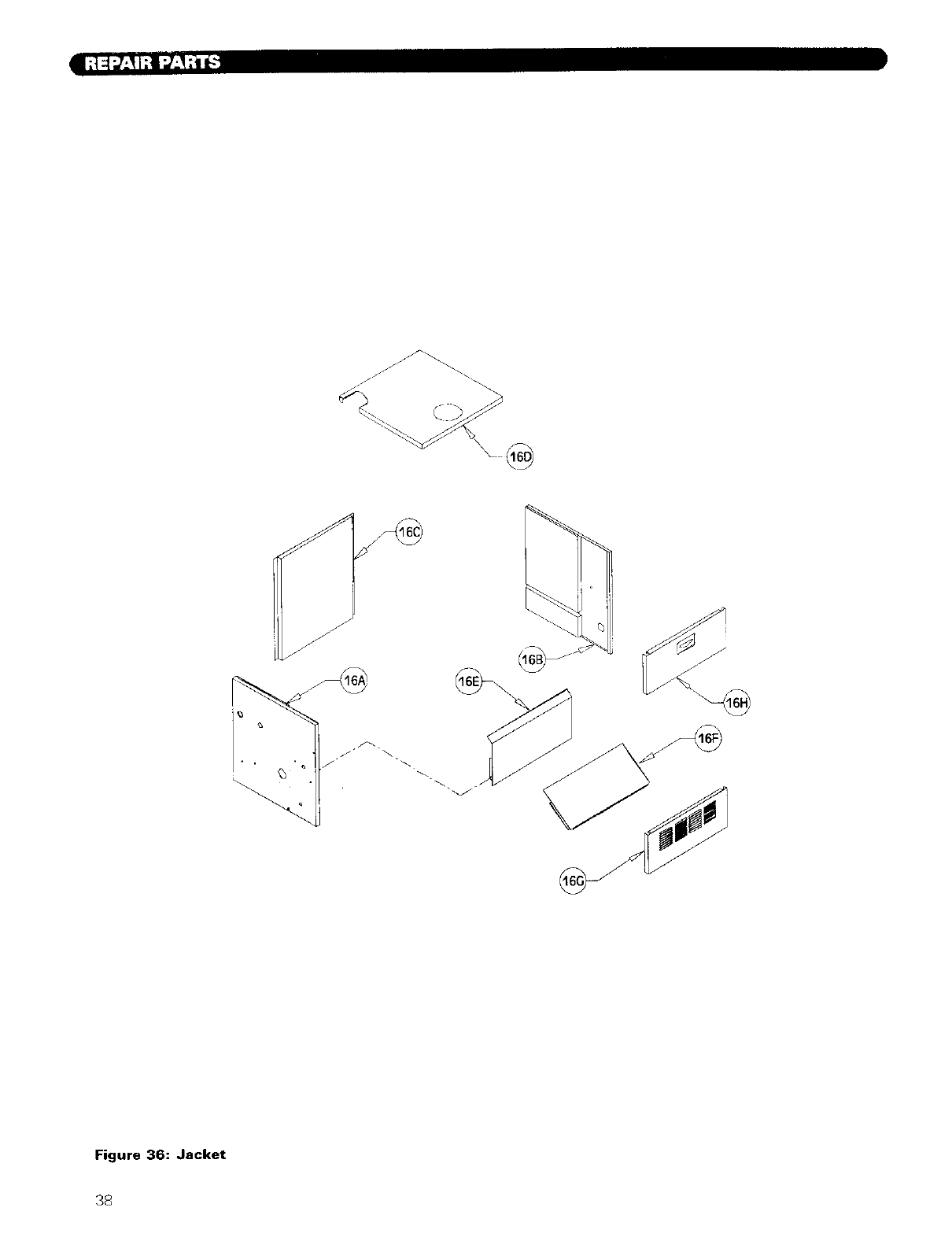
\
Figure 36: Jacket
38
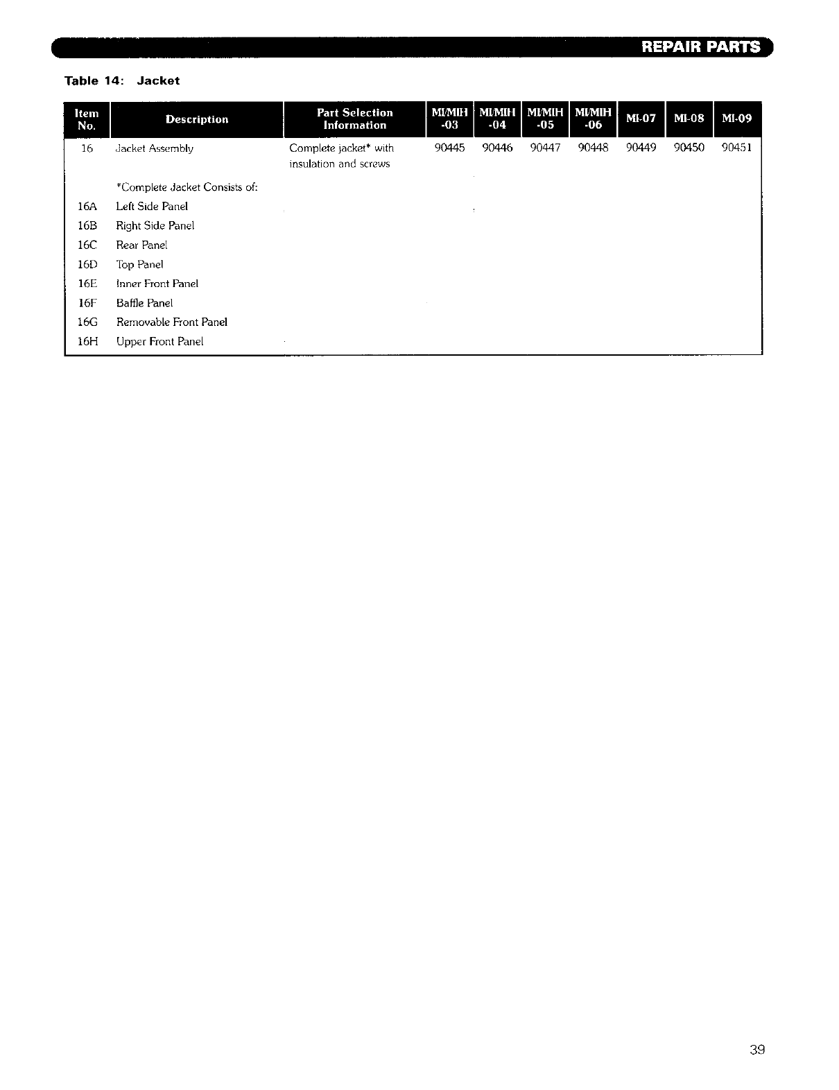
Table 14: Jacket
16 ,Jacket Assembly
*Complete Jacket Consists of:
]6A Left Side Panel
16B Right Side Panel
16C Rear Panel
16D Top Panel
16E Inner Front Panel
16F Baffle Panel
16G Removable Front Panel
16H Upper Front Panel
Complete jacket* with
insulation and screws
90445 90446 90447 90448 90449 90450 90451
39
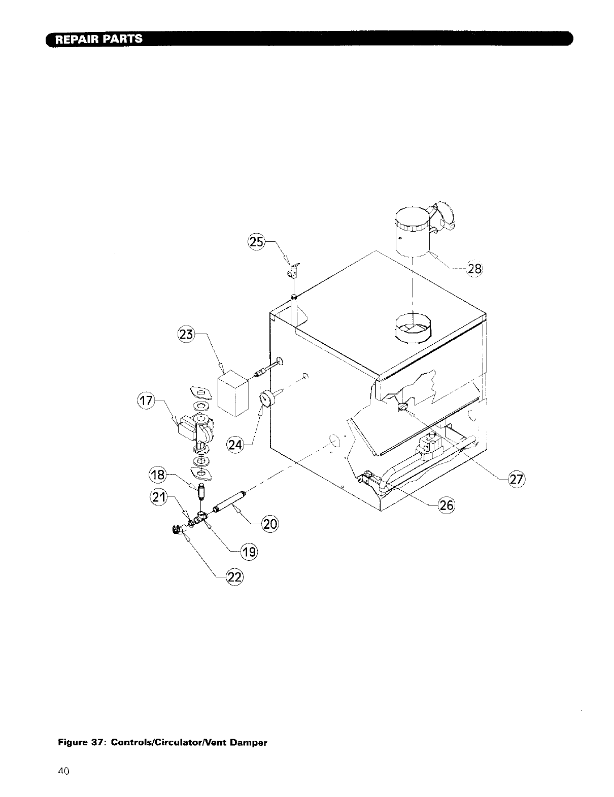
I_t"-Jl_I_ 1;t I=a_l_-']
\
\
I
i
I
Figure 37: Controls/Circulator/Vent Damper
4O
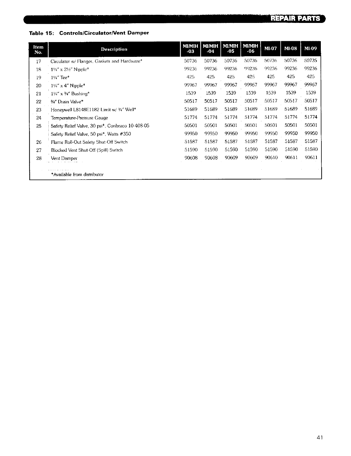
Table 15: Controls/Circulator/Vent Damper
17 Circulator w/Flanges. Gaskets and Hardware*
18 1%" x 2_//' Nipple*
19 1%" Tee*
20 11/4" x 4" Nipple*
21 IV4" x 3/4" Bushing*
22 3/4"Drain Valve*
23 Honeywell L8148E1182 Limit w/%" Well*
24 Temperature-Pressure Gauge
25 ! Safety Relief Valve, 30 psi*. Conbraco 10-408 05
Safety Relief Valve, 50 psi*, Watts #350
26 Flame Roll-Out Safety Shut Off Switch
27 Blocked Vent Shut Off (Spill) Switch
28 Vent Damper
*Available from distributor
50736
99236
425
99967
1539
50517
51689
51774
50501
99950
51587
51590
90608
50736 50736
99236 99236
425 425
99967 99967
1539 1539
50517 50517
51689 51689
51774 51774
50501 50501
99950 99950
51587 51587
51590 51590
90608 90609
50736 50736
99236 99236
425 425
99967 99967
1539 1539
50517 50517
51689 51689
51774 51774
50501 50501
99950 99950
51587 51587
51590 51590
90609 90610
50736 50735
99236 99236
425 425
99967 99967
1539 1539
50517 50517
51689 51689
51774 51774
50501 50501
99950 99950
51587 51587
51590 51590
90611 90611
41

Series MI/MIH
Gas Boilers
Installation,
Operation
Maintenance
Manual
TO THE INSTALLER:
This manual is the property of the owner and must
be affixed near the boiler for future reference.
TO THE OWNER:
This boiler should be inspected annually by a
Qualified Service Agency.
HI Division ASME
of gama
PEr-I_LESS ®
CAST IRON BOILERS
PEERLESS HEATER COMPANY
231 NORTH WALNUT STREET •BOYERTOWN, PA 19512-1021 •PHONE 61_367-2153
vvww.peerless-heater.com
THE PREFERRED HEATING CHOICE
@2002 Peerless Heater Company MI8038 R5 (12/02-10M)
Printed in U.S.A.
