PEERLESS Boiler Manual L0308199
User Manual: PEERLESS PEERLESS Boiler Manual PEERLESS Boiler Owner's Manual, PEERLESS Boiler installation guides
Open the PDF directly: View PDF ![]() .
.
Page Count: 61

LC/LCE
Gas/Off Boilers -Steam
Installation,
Operation
Maintenance
Manual
PEERLESS °
CAST IRON BOILERS

22 Sizes 4-24 Sections 4.75 to 32.5 GPH Input Up to 83.7% Combustion Efficiency
Forced Draft Venting
•Only Requires a Three Foot Vent Above the Roof
High Efficiency Power Burners
•Choice ofBeckett, Carlin, Gordon-Piatt, Power Flame or Webster
Integral Cast Iron Flue Collector
•Adds Durability and Reduces Operating Noise
Rear Flue Outlet on LC, Top Flue Outlet on LCE
• Provides Optimum Flue Gas Travel for Increased Efficiency
•Includes Locking Damper
Wet Base Section Design with Tubular Heat Exchanger
•Provides Additional Heating Surface for Optimum Heat Transfer
Safety Controls
•Probe or Float Type Low Water Cut OffAvailable
Tankless Coils
• For Domestic Hot Water Production on Hot Water Boilers
Unique Flex-Seal Flow Port Gaskets
• Injection Molded for Superior Performance and Flexibility
•Assures a Water Tight Seal Between Sections
Individual Draw Rods
•For Ease of Assembly
Insulated Enameled Steel Jacket
•Reduces Bo_er Heat Loss
• Honeywell Operating Controls
•Manual Reset High Limit Control
• LWCO on Packaged Boilers
• Tankless Coils
• Various Burner Opliol_s and Voltages
•FM and IRI Control Syslems
Peerless Boilers is pleased to qlTer one of the most comptz,h_,nsive wantruly programs irl the indttstl y. All Peerless commercial
cast i1oll boil_'rs irlclude a filll, one year it_atTatlty. A limitt_¢t, tell year tt!Cllwa_ll[j Oil lilt; ¢'(ISl ir_)tl ._('cIioIIs is provided.lbr (111 col_l
lTlul'ci¢l{ ]tol It!¢ll_'l CJlICI sleanl boilers. Fivt_ (lll(_ lell year ¢'.k'I¢'llc'l¢!¢l it;(lrl(ltl{i¢'s Oil 11(111.% (llld !¢llx)l ¢1r€" iiott_ available,. /)l¢'(lst' ¢'¢._tt
still Pt'erlt,ss [Joilera.lot complete tv(trratlly it{lbrmaliotl,
Peerless Boilers •610-367-2153 * www.peerless-heater.com
FA6 LC R3 i3031MI
Pr_n_o_Jirl U S A
pr=-r=-RLESS o
CAST IRON BOILERS
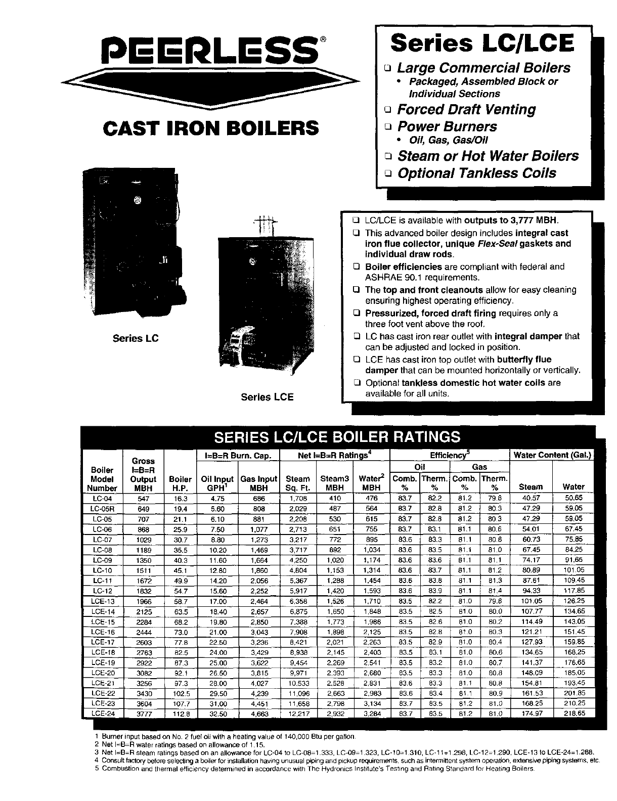
Series LC/LCE
Large Commercial Boilers
• Packaged, Assembled Block or
Individual Sections
oForced Draft Venting
Power Burners
•Oil, Gas, Gas/Oil
QSteam or Hot Water Boilers
Optional Tankless Coils
Series LC
Series LCE
Net I=B=R Ratings 4 Efficiency 5Water Content
Oil Gas
.... I I m
Model Output Boiler Oil Input Gas Input l Steam Steam3 Water 2Comb. Therm. Comb. Therm.
Number MBH H,P. GPH 1MBH Sq. Ft. MBH MBH % % % % Steam Water
LC-O4 547 16.3 4.75 686 1,708 410 476 83.7 82.2 81.2 79.8 40.57 50,65 mm
,0.05,_,9 19.4 5.60 80_ 2.029,7 56, _.7 62.561.290._47.29 69.0,m
LC-05 707 21.1 6.10 881 2,208 530 615 83.7 82.8 81.2 803 47.29 59.05 II
LC-06 866 25.9 7.59 1,077 2,713 651 755 83.7 83,1 81,1 80.8 54.01 67.45 I
LC-07 1029 30.7 8.80 1,273 3,217 772 895 83.6 83.3 61.1 806 60.79 75.55 I
LC-08 1189 35.5 10.20 1,469 3,717 892 1,034 83.6 835 61.1 81.0 67.46 84.25 I
LC-09 1350 40.3 11.60 1,864 4,250 1,020 1,174 83,6 83.6 811 81.1 74.17 91.65 I
LC-10 1511 45.1 12.80 1,860 4,804 1,153 1,314 83.6 83.7 81.1 81.2 80.88 101,05 I
LC-11 1872 48.9 14.26 2,056 5,367 1,288 1,454 63.6 83.8 811 81.3 87,61 109,45 I
LC-12 1832 54,7 15.60 2,252 5,917 1,420 1,593 83.6 83.9 811 814 94.33 117,65 I
LCE-13 1966 58.7 17,00 2,464 6,358 1,526 1,710 83,5 822 61.0 79,8 101.05 126,25 I
LCE-14 2128 83.5 18.40 2,657 6,875 1,650 1,848 83.5 625 810 80.0 107.77 134,65 •
LCE-15 2284 66,2 19.80 2,850 7,388 1,773 1,986 83.5 826 510 80.2 114.49 143,05 I
LCE-16 2444 73,0 21.00 3,043 7,908 1,896 2,125 83.5 82.8 610 80.3 121.21 151.45 I
LCE-17 2603 77.8 22.50 3,236 8,421 2,021 2,283 83.5 629 81.0 80.4 t 27.93 15985 I
LCE-18 2763 82.5 24.00 3,429 6,938 2,145 2,403 83.5 83.1 810 80.6 134.65 168.25 I
LCE-19 2922 87.3 2500 3,622 9,454 2,289 2,541 83,5 83.2 81.0 80.7 141.37 176.65 I
LCE-80 3082 92.1 2650 3,815 9,971 2,393 2,680 83.5 833 810 806 148,09 18505 I
LCE-21 3256 97.3 2800 4,027 10,533 2,528 2,831 83.6 63 3 81 1 809 15481 19345 I
LCE-22 3430 102.5 29.80 4,239 11,096 2,663 2,983 83.6 834 8t 1 808 161.53 20185 •
LCE-23 3604 107.7 31.00 4,451 11,658 2,798 3,134 83.7 835 812 81.0 168.25 210.25 •
LCE-24 3777 1128 32,50 4,663 12,217 2,932 3,284 83.7 835 812 81.0 174.97 218.65 I
1 Burner input based on No. 2 fuel oit with a beating value of 140,000 Btu per garlon
2 Net I_B-R water ratings based on allowance of 1.15.
3 Net I=B-R steam ratings based on an allowance for LC-04 to LC-05 1.333, LC-09 1.323, LC-10-1.310, LC-11=1.298, LC-12 1.290, LCE-13 to LCE-24=1.288.
4 Consult factory before selecting a boiler for installation having unusual piping and pickup requirements, such as intermitlent system operation, extensive piping systems, etc
5 Combustion and thermal efficiency determined in accordance with The Hydronics Institute's Testing and Rating Standard for Heating Boilers
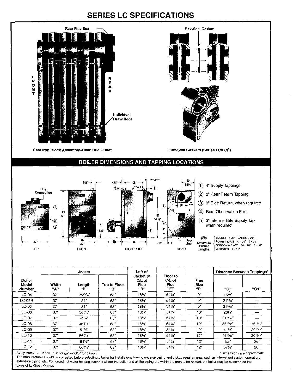
SERIES LC SPECIFICATIONS
F_[o]llll=l_ I_]]_r_l_J_.-][o_[,."]F_1Lqi]If.'1_ ][e[_ _[,,.'!1
Boiler
Model
Number
LC-04
LC-05R
LC-05
LC-06
LC-07
LC-08
LC-09
LC-10
LC-11
LC-12
Width
"A"
37"
37"
37"
37"
37"
37"
37"
37"
37"
37"
Jacket
Length
"B"
25_%#'
31"
31"
36¼s"
41W'
46%6"
513/."
56%#'
61½"
66%s"
Top to Floor
63"
63"
63"
63"
63"
63"
63"
63"
63"
63"
Left of Floor to
C/L of
Flue
"E"
54W'
54W'
54W'
541/8 `'
54W'
54W'
541/8 ''
54W'
54W'
54W'
Flue
Size
"F"
9"
9"
9"
10"
10"
10"
12"
12"
12"
12"
Distance Between Tappings*
Jacket to
C/L of
Flue
18W'
181/4 "
18V4"
18_ ,,
18V4"
18V4"
181/4"
18V4"
18W'
18_A,,
liG_l
16_/_"
21_A#'
219/_6"
265/8"
31"/_e"
36_3/_#'
417/_"
46_5/_e"
52"
57W'
"GI"
15_¾6"
20_%6"
20_¾8"
26"
26"
Apply Prefix "O" for oil--"G" for gas--"GO" for gas-oil *Dimensions are approximate
The manufacturer should be consulted before selecting a boiler for installations having unusual piping and pickup requirements, such as intermittent system operation,
extensive piping, etc. For forced hot water heating systems where the boiler and all the piping are within the area to be heated, the boiler may be selected on the
basis of its Gross Output.
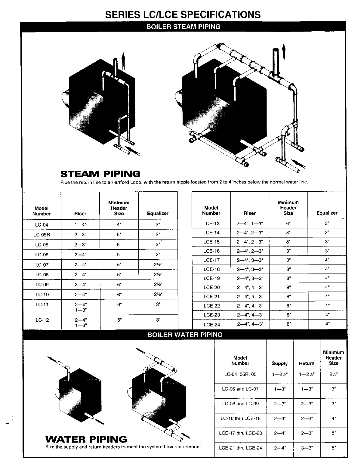
SERIES LC/LCE SPECIFICATIONS
STEAM PIPING
Pipe the return line to a Hartford Loop, with the return nipple located from 2 to 4 inches below the normal water line.
Model
Number
LC-04
LC-O5R
LC-05
LC-06
LC-07
LC-08
LC-09
LC-IO
LC- 11
LC-12
Riser
14"
2--3"
2--3"
24"
24"
24"
24"
24"
24"
1--3"
2_"
Minimum
Header
Size Equalizer
4" 2"
5" 2"
5" 2"
5" 2"
5" 21/2"
6" 21/2"
6" 21/2'
6" 21/2"
6" 3"
6. 3.
14"
Model
Number
LCE-13
LCE-14
LCE-15
LCE-16
LCE-17
LCE-18
LCE-19
LCE-20
LCE-21
LCE-22
LCE-23
Riser
2_4", 1_3"
2_", 2--3"
2_4", 2--3"
2---4", 2--3"
24", _"
2_", 3_3"
24", 3--3"
24", 4_3"
24", 4---3"
2_4", 4---3"
24", 4--3"
Minimum
Header
Size
6"
8"
8"
8"
8"
8"
6"
8"
8"
8"
6"
6"
Equalizer
3"
3"
3'=
3"
4"
4"
4"
4"
4"
4"
4"
4"
WATER PIPING
Size the supply and return headers to meet the system flow requirement.
Model
Number
LC-64, 85R, 65
LC-06 and LC-07
LC-68 and LC-09
LCqO thru LCE-16
LCE-17 thru LCE*20
LCE-21 thru LCE*24
Supply Return
1--2W' 1--2Vz"
1--3" 1--3"
2--3" 2--3"
2--4" 2--3"
2_" 2--3"
24" 3-3"
Minimum
Header
Size
21/2,,
3"
3"
4"
6"
5"
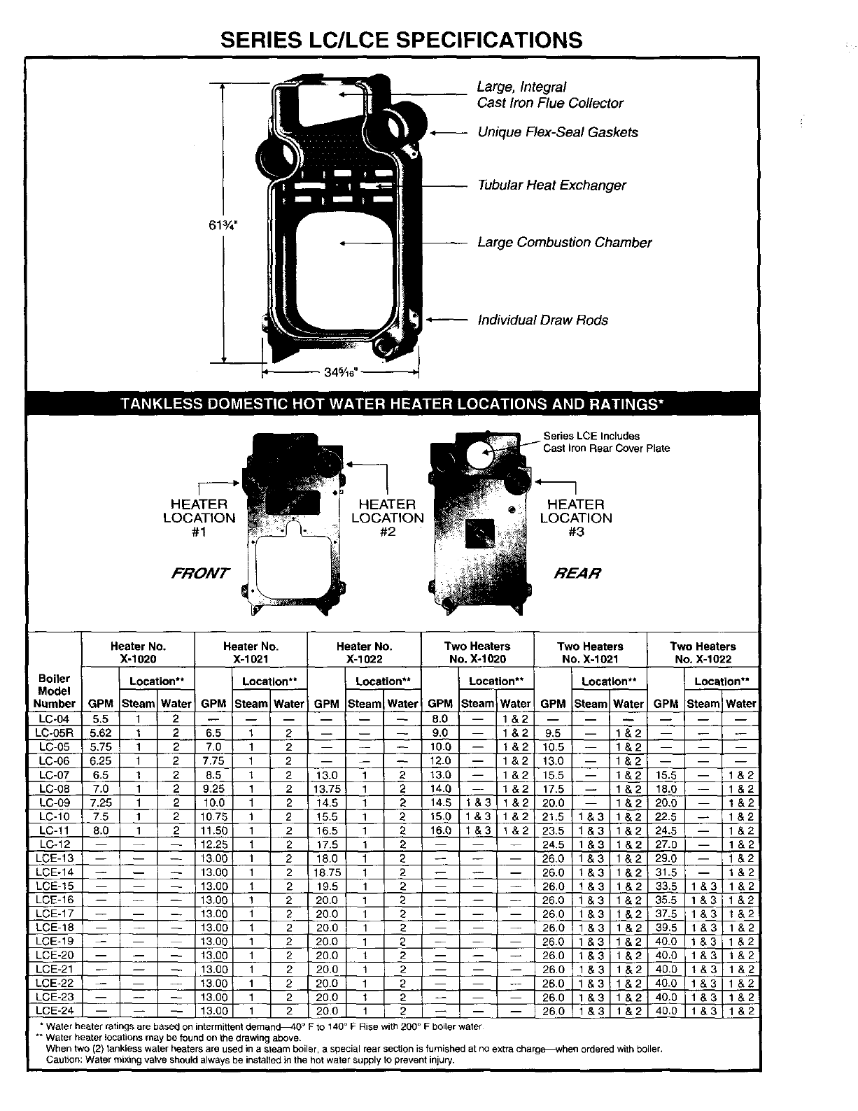
SERIES LC/LCE SPECIFICATIONS
613/4"
-- --_ 345,46,,
Large, Integral
Cast Iron Flue Collector
Unique Flex-Seal Gaskets
-- Tubular Heat Exchanger
-- Large Combustion Chamber
Individual Draw Rods
HEATER
LOCATION
#1
FRONT
HEATER
LOCATION
#2
I
_ Series LCE Includes
E _i Cast lron Rear Cover Plate
_:m - _ LOCATION
Heater No.
X-1020
Boiler Location**
Model mTw
Number GPM Stea ater
LC-04 5.5 1 2
LC-O5R 5.62 t 2
LC-05 5.75 1 2
LC-06 6.25 1 2
LC-07 6.5 1 2
LC-08 7.0 1 2
LC-09 7.25 1 2
LC-10 7.5 1 2
LC-11 8.0 1 2
LC-12
LCE-13
LCE-14
LCE-15
LCE-16
LCE-17
LCE-18
LCE-19
LCE-20
LCE-21
LCE-22
LCE-23
LCE-24
Heater No. Heater No. Two Heaters Two Heaters
X-1021 X-1022 No. Xo1020 No. X-1021
Location** Location** Location** Location**
GPM SteamlWater GPM Steam Water GPM Steam Water GPM ,Steam Water
8.0 -- 1&2
Two Heaters
No. X-1022
Location**
GPM Steam Wate!
13.00 1 2 20.0 1 2 1 & 2
" Water heater rahngs are based on intermittent deman_O ° P to 140 ° F Rise with 200 ° Fboiler water
** Water beater locations may be found on the drawing above.
When two (2) tankless water heaters are used in asteam boiler, a special rear section is furnished at no extra charg_when ordered with boiler,
Caution: Water mixing valve should always be installed in the hot water supply to prevent injury.
6.5 129.0 -- 1 & 2 9,5 -- 1&2
7.0 1 2 10.0 -- 1&2 10.5 -- 1&2
7.75 1 2 12.0 -- 1&2 13.0 -- 1&2
8.5 1 2 13.0 1 2 13.0 -- 1&2 15.5 -- 1&2 15.5 -- 1&2
9.25 1 2 13.75 1 2 14.0 -- 1 & 2 17.5 -- 1 & 2 18.0 -- 1 & 2
10.0 1 2 14.5 1 2 14.5 1&3 1&2 20.0 -- 1&2 20.0 -- 1&2
10.75 1 2 15.5 1 2 15,9 1&3 1&2 21.5 1&3 1&2 22.5 -- 1&2
11.56 1 2 16.5 1 2 16.0 1&3 1&2 23.5 1&3 1&2 24.5 -- 1&2
12.25 1 2 17.5 1 2 ..... 24.5 1&3 1&2 27.0 -- 1&2
13,00 1 2 18.0 1 2 26,0 1&3 1&2 29.0 -- 1&2
13.00 1 2 18.75 12 ..... 26.0 1&3 1&2 31.5 -- 1&2
13.00 1 2 19.5 1 2 ..... 26.0 1&3 1&2 33.5 1&3 1&2
13.00 1 2 20.0 1 2 26.0 1&3 1&2 35.5 1&3 1&2
13.00 1 2 20.0 1 2 - IZI I __I-- 26.0 1&3 1&2 37.5 1&3 1&2
13.00 1 2 20,0 1 2 26.0 1&3 1&2 39.8 1&3 1&2
13.00 1 2 20.0 1 2 ..... 26.0 1&3 1&2 40.0 1&3 1&2
13.00 1 2 20.0 1 2 ..... 26.0 1&3 1&2 40.0 1&3 1&2
13.00 1 2 20.0 1 2 ..... 26.0 1&3 1&2 40.0 1&3 1&2
13.00 1 2 20.0 1 2 26.0 11&3 1&2 40.0 1&3 1&2
i
13.00 1 2 20.0 I2 -- 26.0 11&3 1&2 40:0 1&3 1&2
, -- ' -- 26.0 I 1&3 40.0 1&3 1&2
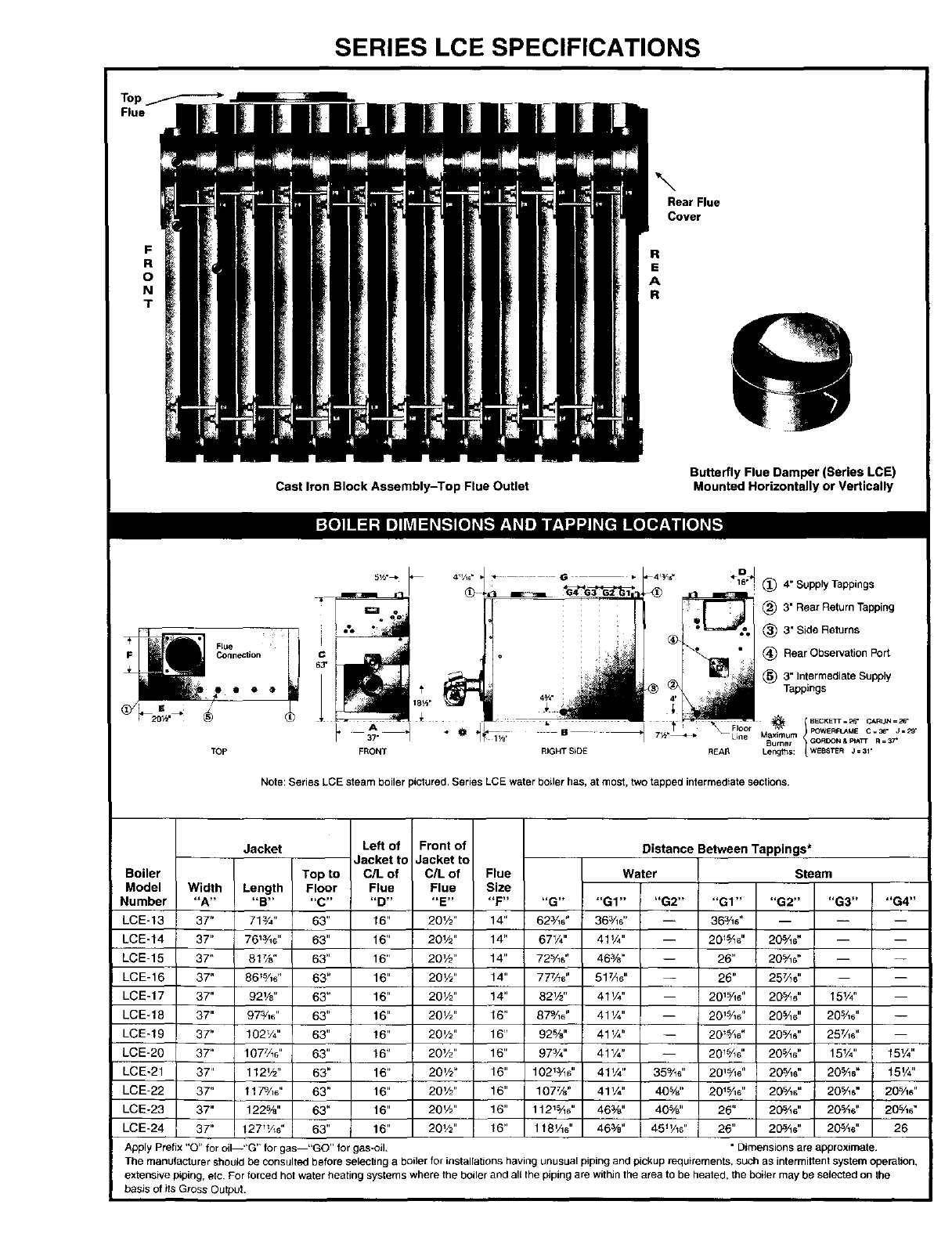
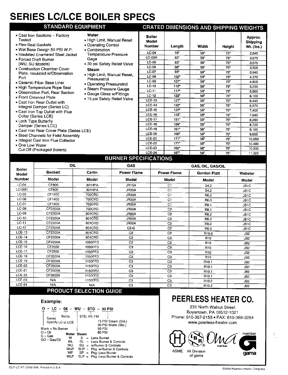
SERIES LCE SPECIFICATIONS
\Rear Flue
Cover
R
E
A
R
Cast Iron Block Assembly-Top Flue Outlet Butterfly Flue Damper (Series LCE)
Mounted Horizontally or Vertically
TOp
_l_ <D I
4_/,_" • .* G_ 4,_,_¢ 16'_1(_ 4"SupplyTappings
]- : _ (_) 3"RearReturnTapping
• I=.=._o _) 3"Side Returns
c" Re"r°b e 'ati°nF "
63" T_3"IntermediateSupply
"ii __, 4_/£ Tappings
37" @ lye Line M_ximum POWERFLAMEC=36"
Burner G CRDON &RATr R = _7 _
FRONT RIGHT SSDE REAR Lengths: WEBSTER J=31"
Note: Series LCE steam boiler pictured, Series LCE water boiler has, at most, two tapped intermediate sections.
Boiler
Model
Number
LCE-13
LCE-t4
LCE-15
LCE-16
LCE-17
LCE-18
LCE-19
LCE-20
LCE-21
LCE-22
LCE-23
LCE-24
Width
"A"
37"
37"
37"
37"
37"
37"
37"
3T'
37"
37"
37"
37"
Jacket Left of Front of
Jacket to Jacket to
Top to C/L of C/L of Flue
Length Floor Flue Flue Size
"B .... C.... D.... E.... F"
715/4" 63" 16" 20%" 14"
76_5/16" 63" 16" 20V2" 14"
81%" 63" 16" 20%" 14"
86_%6" 63" 16" 201/2" 14"
92 Vs" 63" 16" 20V2" 14"
97_A6" 63" 16" 20V2" 16"
102W' 63" 16" 20'/2" 16"
1077/_s'' 63" 16" 20'/2" 16"
112W' 63" 16" 20%" 16"
1179/,6" 63" 16" 20%" 16"
122%" 63" 16" 20W' 16"
127_/_ " 63" 16" 201/2" 16"
Distance Between Tappings*
Water Steam
"G .... G1 .... G2 .... G1.... G2 .... G3 .... G4"
625/16" 363/16" -- 365/16" -- -- --
67V4" 41%" -- 201-%6" 20%6" -- --
72%6" 46%" -- 26" 20%6" -- --
777/_6' 517/_6" -- 26" 255/_6" -- --
82W' 41%" -- 2015/'16" 20_/_e" 151/'4" --
875/16" 41V4" -- 20_%6" 205/_e" 205/_6" --
92%" 41 _/4" -- 20_16" 205/16 " 257/16 " --
973/'4" 41%" -- 2015/;6" 205/16" 15Y_" 15%"
102_3/_" 41VZ' 35%6" 2015/16" 205/16" 205/16" 15%"
107%" 41V." 40%" 2O_/_e" 20%s" 20%6" 205/_6"
1121%_" 46%" 40%" 26" 20_A_" 20%6" 20"%_"
1t81/_" 46%" 45 _/_6" 26" 205/_6" 205/_#' 26
Apply Prefix "O" for oil--"G" for gas "GO" for gas-oil. " Dimensions are approximate.
The manufacturer should be consulted before selecting a boiler for installations having unusual piping and pickup requirements, such as intermittent system operation,
extensive piping, etc For forced hot water heating systems where the boiler and all the piping are within the area to be heated, the boiler may be selected on the
basis of its Gross Output.
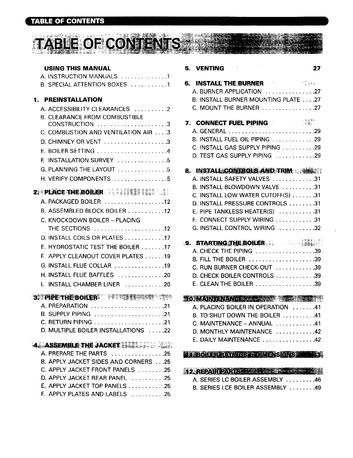
SERIES LC/LCE BOILER SPECS
• Cast Iron Sections- Factory
Tested
• Flex-Seal Gaskets
• Wet Base Desi_.. 50 PSI W.P.
• Insulated Enameled Steel Jacket
• Forced Draft Burner
(WU, SU Models)
• Combustion Chamber Cover
Plate, Insulated w/Observation
Port
• Ceramic Fiber Base Liner
• High Temperature Rope Seal
• Observation Port, Rear Section
• Front Cleanout Plate
• Cast Iron Rear Outlet with
Integral Damper (Series LC)
• Cast Iron Top Outlet with Flue
Collar (Series LCE)
• Lock Type Butterfly
Damper (Series LCE)
• Cast Iron Rear Cover Plate (Series LCE)
• Steel Channels for Field Assembly
• Integral Cast Iron Flue Collector
• One Low Water
Cut-Off (Packaged Boilers)
Water
•High Limit,Manual Reset
•OperatingControl
•Combination
Temperature-Pressure
Gage
•30 psi Safety Relief Valve
Steam
•High Limit,Manual Reset,
Pressuretrol
•Operating Pressuretrol
•Steam Pressure Gauge
• Gauge Glass w/Fittings
• 15 psi Safety Relief Valve
Model
Number
LC-04
LC-05R
LC-05
LC-O6
LC-07
LC-08
LC-09
LC-10
LC-11
LC-12
LCE-13
LCE-14
LCE-15
LCE-16
LCE-17
LCE-18
LCE-19
LCE-20
LCE-2r
LCE-22
LCE-23
Boiler
Model
Number
LC_4
LC-05R
LC-05
LC-06
LC-07
LC-08
LC-O9
LC-10
LC-11
LC-12
LCE-13
LCE-14
LCE-15
LCE-16
LCE-17
LCE-18
LCE-19
LCE-20
LCE-21
LCE-22
LCE-23
LCE-24
Length
78"
83"
83"
88"
93"
102"
107"
112"
117"
122"
127"
132"
137"
142"
151"
156"
161"
166"
171"
177"
182"
187"
Width
58"
58"
58"
58"
58"
58"
58"
58"
58"
58"
58"
58"
58"
58"
58"
58"
58"
58"
58"
58"
58"
Height
75"
75"
75"
75"
75"
75"
75"
75"
75"
75"
75"
75"
75"
75"
75"
75"
75"
75"
75"
75"
75"
Approx.
Shipping
Wt. (Ibs.)
2,645
3,075
3,075
3,505
3,940
4,370
4,805
5,235
5,665
6,100
6,495
6,970
7,405
7,840
8,280
8,720
9,165
9,605
10,050
I0,490
10,930
GAS GAS, OIL, GAS/OIL
Beckett Carlin Power Flame Power Flame Gordon Piatt Webster
Model
CFS00
CF800
CF1400
CF1400
CF1400
CF2300A
CF2300A
CF2300A
CF2300A
CF2300A
CF2300A
CF2300A
CF2300A
CF2506
CF2500
CF3500A
CF3500A
CF3500A
CF3500A
CF3500A
N/A
Model
JR15A
JR30A
JR30A
JR30A
JR30A
JR50A
JR50A
JRSOA
JR50A
C2-G
C2
C2
C2
C3
C3
C3
C3
C3
C3
C3
C3
Example:
Model
301HPA
301HPA
702CRD
702CBD
702CBD
702CRD
601CRD
801CRD
801CRD
501CRD
801CRD
801CRD
1050FFD
1050FFD
1150FFD
1150FFD
1150FFD
1150FFD
1150FFD
1150FFD
1150FFD
O - LC -06 - WU - STD -30PSI
/Sects. STD, IRI, FM
Series
Specify LC or LCE 15 PSI Steam (Std.)
30 PSI Water (Std.)
Blank = No Burner 50 PSi
O = Oil Water Steam 80 PSI
G = Gas W S = Less Burner
GO- Gas/Oil WL SL -Less Burner & Controls
WU SU = w/Burner& Controls
WUP SUP - Pkg. w/Burner & Controls
WP SP = Pkg. Less Burner
WLP SLP = Pkg Less Burner & Controls
Model
C1
C1
C1
C1
C1
C2
C2
C2
C2
C2
C2
C2
C2
C3
C3
C3
C3
C3
C3
C3
C3
C3
Model
$4.2
$4.2
R6.2
R6.3
R8.1
R8.1
R8.2
R8.2
R8.2
R8,3
R10.9
R10
R10
R10
R10
R10
R10.1
R10.1
R10.1
R10.1
R10.2
R10.2
i
Model
JB1C
JB1C
JBIC
JB1C
JB1C
JB1C
JB1C
JB1C
JB1C
JB1C
JB2
JB2
JB2
JB2
JB2
JB2
JB2
Ja2
JB2
JB2
JB2
JB2
m
PEERLESS HEATER CO.
231 North Walnut Street
Boyertown, PA 19512-1021
Phone: 610-367-2153 • FAX: 610-369-3284
www.peerless-heater.com
ASME HI Division member • _1
of gama ganla
CUT-LC R7 (12/02.5M) Printed in US A @2002 peerPess Heater Compan
1,
USING THIS MANUAL
A. INSTRUCTION MANUALS .............. 1
B. SPECIAL ATTENTION BOXES ........... 1
PREINSTALLATION
A. ACCESSIBILITY CLEARANCES .......... 2
B. CLEARANCE FROM COMBUSTIBLE
CONSTRUCTION ..................... 3
C. COMBUSTION AND VENTILATION AIR .... 3
D. CHIMNEY OR VENT ................... 3
E. BOILER SETTING ..................... 4
E INSTALLATION SURVEY ............... 5
G. PLANNING THE LAYOUT ............... 5
H. VERIFY COMPONENTS ................ 5
A. PACKAGED BOILER .................. 12
B. ASSEMBLED BLOCK BOILER ........... 12
C. KNOCKDOWN BOILER - PLACING
THE SECTIONS ..................... 12
D. INSTALL COILS OR PLATES ............ 17
E. HYDROSTATIC TEST THE BOILER ....... 17
E APPLY CLEANOUT COVER PLATES ...... 19
G. INSTALL FLUE COLLAR ............... 19
H. INSTALL FLUE BAFFLES .............. 20
I. INSTALL CHAMBER LINER ............ 20
5, VENTING 27
.INSTALL THE BURNER
A. BURNER APPLICATION ............... 27
B. INSTALL BURNER MOUNTING PLATE .... 27
C. MOUNT THE BURNER ................ 27
7. CONNECT FUELPIPING
A. GENERAL .......................... 29
B. INSTALL FUEL OIL PiPiNG ............. 29
C. INSTALL GAS SUPPLY PIPING .......... 29
D. TEST GAS SUPPLY PIPING ............ 29
8, ;It
A. INSTALL SAFETY VALVES ............. 31
B. INSTALL BLOWDOWN VALVE .......... 31
C. INSTALL LOW WATER CUTOFF(S) ....... 31
D. INSTALL PRESSURE CONTROLS ........ 31
E. PIPE TANKLESS HEATER(S) ........... 31
E CONNECT SUPPLY WIRING ............ 31
G. INSTALL CONTROL WIRING ........... 32
A. CHECK THE PIPING .................. 39
B. FILL THE BOILER .................... 39
C. RUN BURNER CHECK-OUT ............ 39
D. CHECK BOILER CONTROLS ............ 39
E. CLEAN THE BOILER .................. 39
A. PREPARATION ...................... 21
B. SUPPLY PIPING ..................... 21
C. RETURN PIPING ..................... 21
D. MULTIPLE BOILER INSTALLATIONS ..... 22
A. PREPARE THE PARTS ................ 25
B. APPLY JACKET SIDES AND CORNERS ...25
C. APPLY JACKET FRONT PANELS ........ 25
D. APPLY JACKET REAR PANEL .......... 25
E. APPLY JACKET TOP PANELS ........... 25
E APPLY PLATES AND LABELS .......... 25
A. PLACING BOILER IN OPERATION ....... 41
B. TO SHUT DOWN THE BOILER .......... 41
C. MAINTENANCE - ANNUAL ............ 41
D, MONTHLY MAINTENANCE ............ 42
E. DAILY MAINTENANCE ................ 42
A. SERIES LC BOILER ASSEMBLY ......... 46
B. SERIES LCE BOILER ASSEMBLY ........ 49
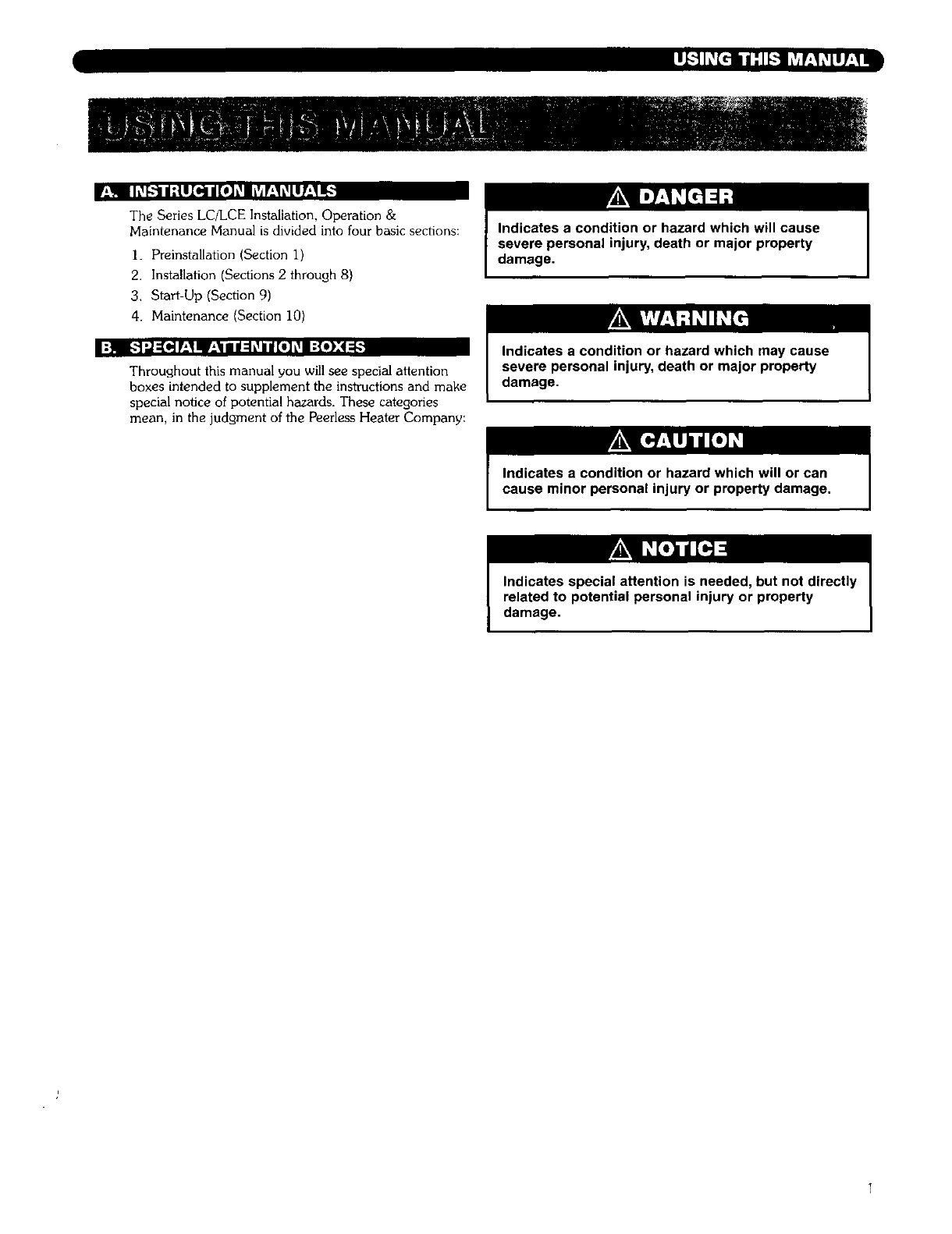
r*_l IL_['-'_I/:tII_/[e]L_I LvJ¥±_L_Ir-'_
The Series LC/LCE Installation, Operation &
Maintenance Manual is divided into four basic sections:
I. Preinstallation (Section I)
2. Installation (Sections 2 through 8)
3. Start-Up (Section 9)
4. Maintenance (Section 10)
:H _.'_'.,I:[_P_I! F-_III:IL_Ii[O]L_I ;{*):4:[,
Throughout this manual you will see special attention
boxes intended to supplement the instrudions and make
special notice of potential hazards. These categories
mean, in the judgment of the Peerless Heater Company:
Indicates a condition or hazard which may cause
severe personal injury, death or major property
damage.
Indicates special attention is needed, but not directly
related to potential personal injury or property
damage.
Theequipmentmustbeinstalledinaccordancewithinstallationrequirementsoftheauthorityhaving
jurisdictionor,intheabsenceofsuchrequirements,to thecurrenteditionoftheNational Fuel Gas Code, ANSI
Z223.1/NFPA 54.
Where required by the authority having jurisdiction, the installation must conform to American Society of
Mechanical Engineers Safety Code for Controls and Safety Devices for Automatically Fired Boilers, ASME CSD-I.
Carefully read these instructions and the Ignition System and Conbols Manual before beginning work. Understand all aspects of
the installation. Contact your Peerless Heater Company sales representative or customer service for help in answering questions.
This boiler must be installed by a qualified contractor. The boiler warranty can be voided if the boiler is not installed correctly.
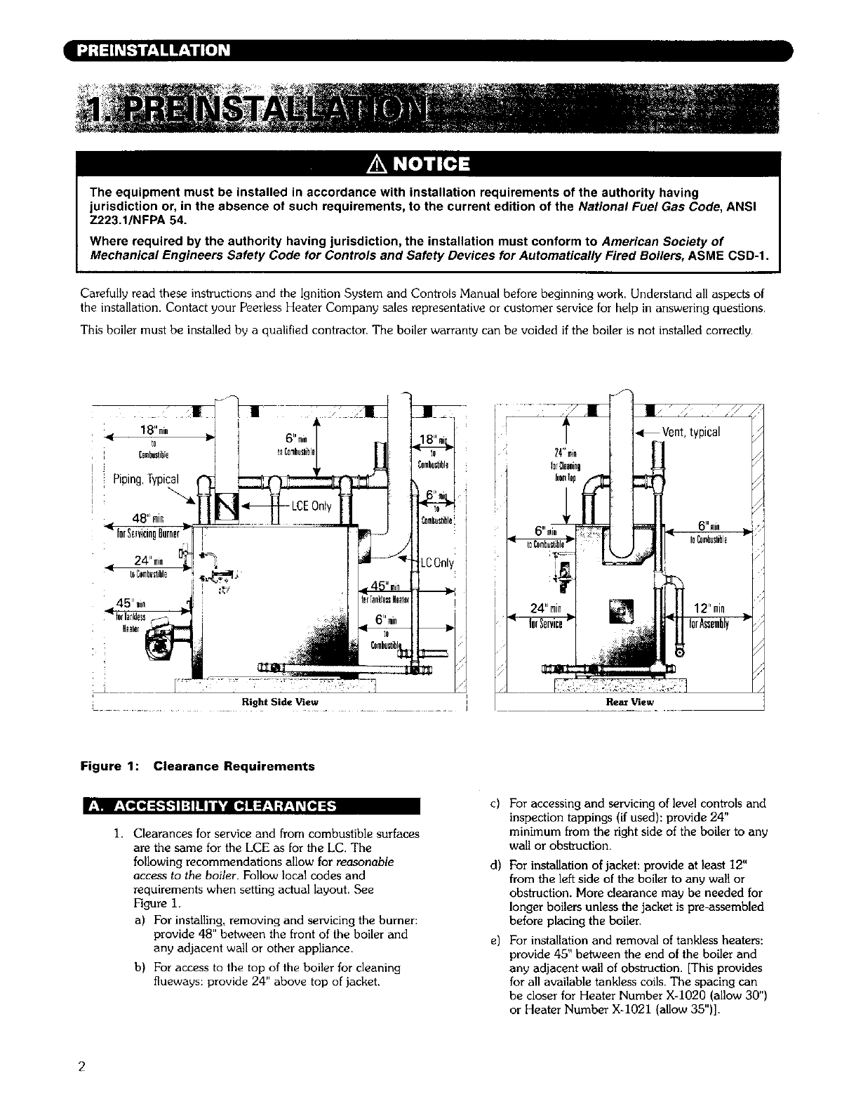
Right Side View Rear View
Figure 1: Clearance Requirements
r,_l!
1. Clearances for service and from combustible surfaces
are the same for the LCE as for the LC. The
following recommendations allow for reasonable
access to the boiler. Follow local codes and
requirements when setting actual layout. See
Figure 1.
a) For installing, removing and servicing the burner:
provide 48" between the front of the boiler and
any adjacent wall or other appliance.
b) For access to the top of the boiler for cleaning
flueways: provide 24" above top of jacket.
c) For accessing and servicing of level controls and
inspection tappings (if used): provide 24"
minimum from the right side of the boiler to any
wall or obskuction.
d) For installation of jacket: provide at least 12"
from the left side of the boiler to any wall or
obstruction. More clearance may be needed for
longer boilers unless the jacket is pre-assembled
before placing the boiler.
e) For installation and removal of tankless heaters:
provide 45" between the end of the boiler and
any adjacent wall of obstruction. [This provides
for all available tankless coils. The spacing can
be closer for Heater Number X-1020 (allow 30")
or Heater Number X4021 (allow 35")].
h
oN [*.]-'liLVJlk_l:i'4[a):]LvJq_l
Provide the following minimum clearances to
combustible construction• See Figure i.
.,i [I,{.]_VJl:{l_"_l/[e]_._lf±lL'_llp]ivJ::lL_b/llV___l/[O]l._lV'_II;
2,
3.
4,
I Sides: 6"
2. Rear of Jacket: 6"
3. Front of Jacket: 24**
4. Top of Jacket: 24"
5. Steam and Hot Water Pipes: 6"
6. Vent or Chimney Connector: 18"
The installation must provide adequate air for
combustion and ventilation.
Unless the boiler room construction and natural air
infiltration are sure to provide all the air needed,
provide an opening or duct to the outside with a free
cross sectional area of at least I square inch per
4000 Btuh input for all installed appliances. At high
altitude, increase this requirement 4% for each i000
feet above sea level.
The boiler room must never be under negative
pressure. If exhaust fans or other equipment can
cause a negative pressure in the boiler room, the air
openings and equipment design must be engineered
to assure a neutral or slightly positive pressure in the
boiler room at all times of operation. If the
equipment design and air openings cannot assure
this, then the boiler must be located in an isolated
rOOM.
Using combustion air dampers:
a) If motorized dampers are used on the
combustion and ventilation air openings, wire
them such that they must open when the boiler
tries to operate• They must include a switch
which prevents the boiler from operating if they
do not open. See Figure 2.
I.
2
3.
4.
5.
6.
7.
Inspect the existing chimney or vent system Make
sure it is in good condition• Inspect chimney liner
and repair or replace if necessary•
The vent system and installation must be in
accordance with the current edition of the American
National Standard ANSI/NFPA 21 i, "Chimneys,
Fireplaces, Vents, and Solid Fuel Burning
Appliances", or applicable provisions of the local
building codes. The venting requirements for the
LCE are the same as for the LC. Figure 3 shows the
top flue outlet required on LCE boilers
Chimney/Vent Operation: The vent system must be
sized and installed to remove all combustion
products. If the vent system is not sized properly, the
burner may not operate properly. This can cause
poor combustion or sooting to occur.
If the vent terminates in an area where wind-
generated downdrafts are likely, install a suitable vent
cap which can control wind effects.
This boiler is designed to fire only with a pressurized
fire box. The breeching and vent may be sized for
negative, neutral or positive pressure (no more than
0.I inches water column at the boiler outlet) as
desired. But negative pressure overfire can cause
lifting of the flame and poor combustion or
overheating of the boiler crown sheet•
Forced draft breechings and vents must be sealed
and of heavy gauge steel construction and must
comply with all applicable codes of construction.
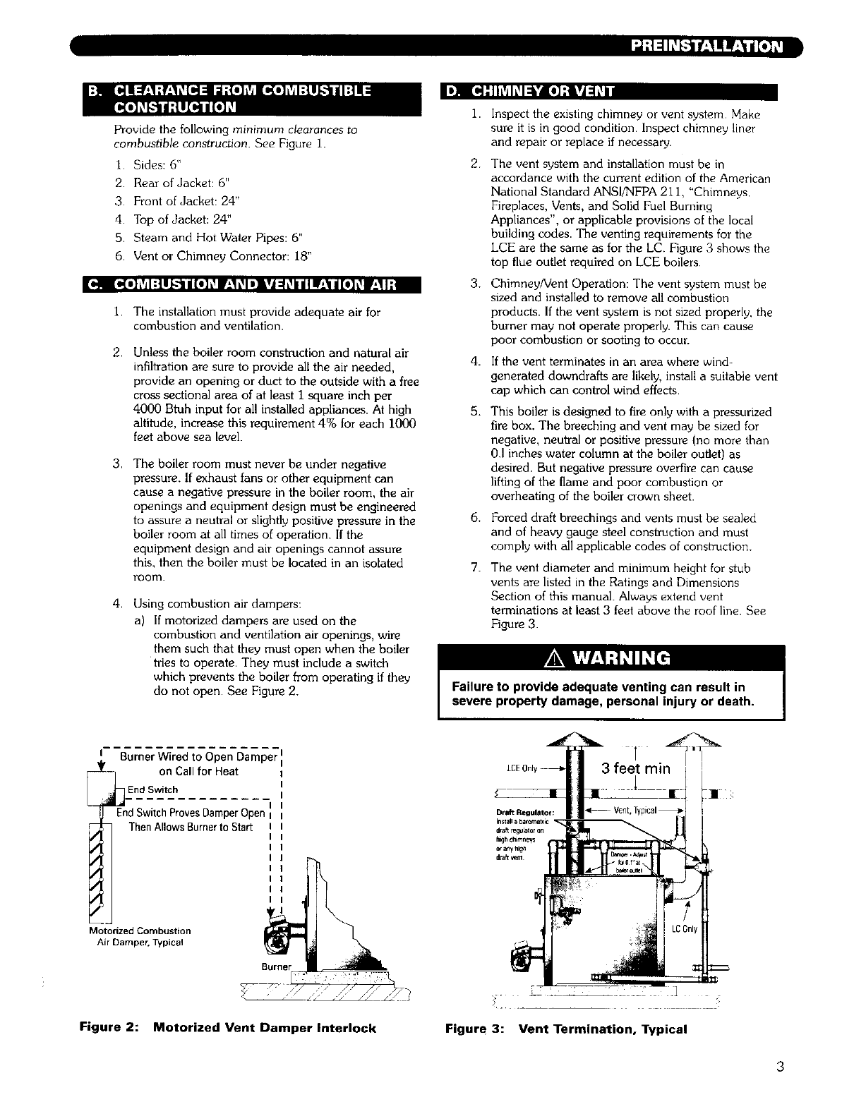
The vent diameter and minimum height for stub
vents are listed in the Ratings and Dimensions
Section of this manual. Always extend vent
terminations at least 3 feet above the roof line. See
Figure 3.
Failure to provide adequate venting can result in
severe property damage, personal injury or death.
IBurner Wired to Open Damper
i_ on Call for Heat
EdSdw/_cV-htC-phrovesDamper Open
Then Allows Burner to Start
Motorized Combustion
Air Damper, Typical
Burner
Figure 2: Motorized Vent Dumper Interlock Figure 3: Vent Termination, Typical
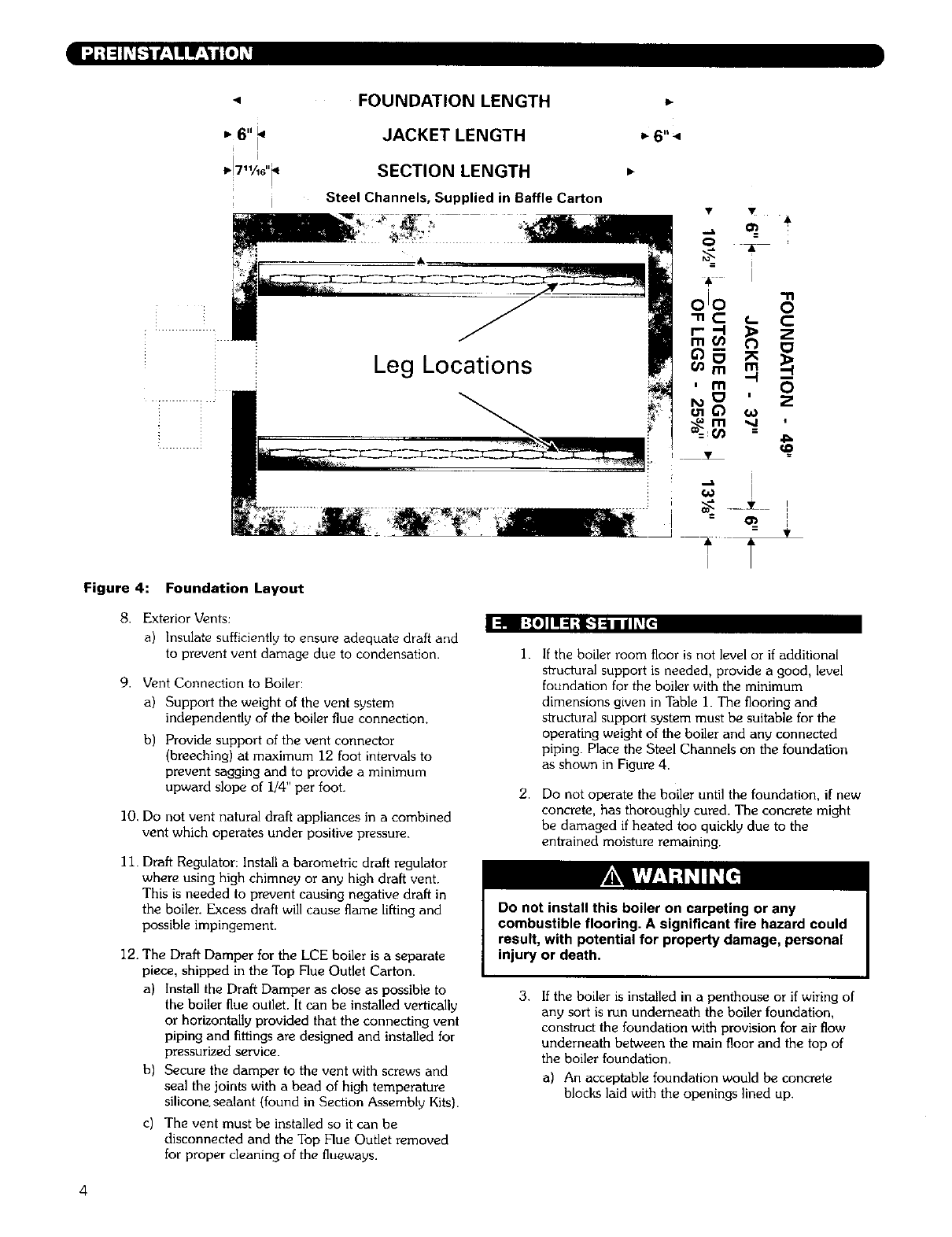
Figure 4:
FOUNDATION LENGTH
JACKET LENGTH
SECTION LENGTH
Steel Channels, Supplied in Baffle Carton
Leg Locations
I
Foundation Layout
8. Exterior Vents:
a) Insulate sufficiently to ensure adequate draft and
to prevent vent damage due to condensation.
I=lli :{0] II =1;__-'1:11/ I_f{
9. Vent Connection to Boiler:
a) Support the weight of the vent system
independently of the boiler flue connection.
b) Provide support of the vent connector
(breeching) at maximum 12 foot intervals to
prevent sagging and to provide a minimum
upward slope of i/4" per foot.
10, Do not vent natural draft appliances in a combined
vent which operates under positive pressure.
11. Draft Regulator: Install a barometric draft regulator
where using high chimney or any high draft vent.
This is needed to prevent causing negative draft in
the boiler Excess draft will cause flame lifting and
possible impingement.
12. The Draft Damper for the LCE boiler is a separate
piece, shipped in the Top Flue Outlet Carton.
a) Install the Draft Damper as close as possible to
the boiler flue outlet. It can be installed vertically
or horizontally provided that the connecting vent
piping and fittings are designed and installed for
pressurized service.
b) Secure the damper to the vent with screws and
seal the joints with a bead of high temperature
silicone, sealant (found in Section Assembly Kits).
c) The vent must be installed so it can be
disconnected and the Top Flue Outlet removed
for proper cleaning of the flueways.
1.
2.
If the boiler room floor is not level or if additional
structural support is needed, provide a good, level
foundation for the boiler with the minimum
dimensions given in Table 1. The flooring and
structural support system must be suitable for the
operating weight of the boiler and any connected
piping. Place the Steel Channels on the foundation
as shown in Figure 4.
Do not operate the boiler until the foundation, if new
concrete, has thoroughly cured. The concrete might
be damaged if heated too quickly due to the
entrained moisture remaining.
Do not install this boiler on carpeting or any
combustible flooring. A significant fire hazard could
result, with potential for property damage, personal
injury or death.
3. Ifthe boiler is installed in a penthouse or if wiring of
any sort is run underneath the boiler foundation,
construct the foundation with provision for air flow
underneath between the main floor and the top of
the boiler foundation.
a) An acceptable foundation would be concrete
blocks laid with the openings lined up.
4
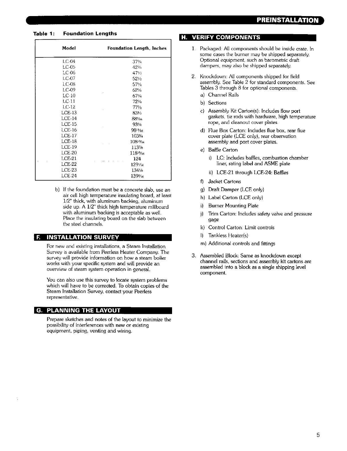
Table 1: Foundation Lengths :Pl gA=1."tI_i_[o] L'_I:,[o1L_I=1L_iiI_
b}
Model Foundation Length, Inches
LC-04 37"/_,
LC 05 42:_,_
LC 06 47V_,
LC-07 521/z
kC-08 57%
LC-09 62%
LC 10 67:_/4
LC 11 72%
kC-12 77%
LCE 13 83'/2
LCE-14 889/16
LCE-15 935A_
LCE-16 98nA6
LCE 17 1033/4
LCE-18 108Wl_
LCE-19 1137/8
LCE 20 118_5/,6
LCE-21 124
LCE-22 129'/16
LCE-23 134'/8
LCE 24 139_/1_
If the foundation must be a concrete slab, use an
air cell high temperature insulating board, at least
I/2" thick, with aluminum backing, aluminum
side up. A I/2" thick high temperature millboard
with aluminum backing is acceptable as well.
Place the insulating board on the slab between
the steel channels.
I_1 IIL_k'tl If;1! IL*_III[o] L_l.'t I J:{vJa '
For new and existing installations, a Steam Installation
Survey is available from Peerless Heater Company. The
survey will provide information on how a steam boiler
works with your specific system and will provide an
overview of steam system operation in general.
You can also use this survey to locate system problems
which will have to be corrected. To obtain copies of the
Steam Installation Survey, contact your Peerless
representative.
I.
2.
3,
Packaged: All components should be inside crate. In
some cases the burner may be shipped separately,
Optional equipment, such as barometric draft
dampers, may also be shipped separately.
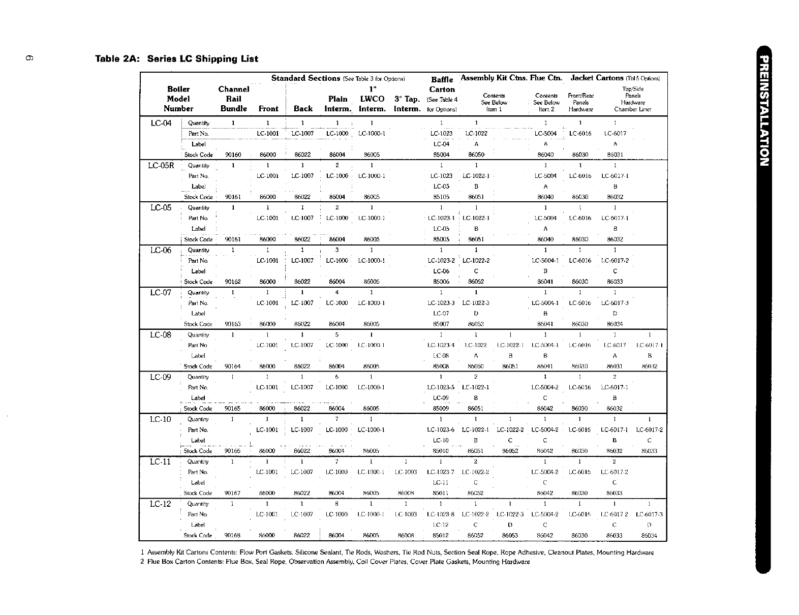
Knockdown: All components shipped for field
assembly, See Table 2 for standard components. See
Tables 3 through 8 for optional components.
a) Channel Rails
b) Sections
c) Assembly Kit Carton(s): Includes flow port
gaskets, tie rods with hardware, high temperature
rope, and deanout cover plates.
d) Flue Box Carton: Includes flue box, rear flue
cover plate (LCE only), rear observation
assembly and port cover plates.
e) Baffle Carton
i) LC: Includes baffles, combustion chamber
liner, rating label and ASME plate
ii) LCE-21 through LCE-24: Baffles
f) Jacket Cartons
g) Draft Damper (LCE only)
h) Label Carton (LCE only)
i) Burner Mounting Plate
j) Trim Carton: Includes safety valve and pressure
gage
k) Control Carton: Limit controls
I) Tankless Heater(s}
m) Additional controls and fittings
Assembled Block: Same as knockdown except
channel rails, sections and assembly kit cartons are
assembled into a block as a single shipping level
component.
[_ I:JIF_'I_I_IIL_[€: ii:l_ ilr;\Y.lll
Prepare sketches and notes of the layout to minimize the
possibility of interferences with new or existing
equipment, piping, venting and wiring.
5
(3) Table 2A: Series LC Shipping List
Standard Sections (_e Table 3for Optionsl
Boiler Channel 1" Carton
Contents Contents Front/Rear
Model Rail Plain LWCO 3" Tap. (_ Table4 S¢¢Below SeeBelow _nels
Number Bundle Front Back lnterm, lnterm. Interm. forOpfions) Item1 Item2 Hardware
] PartNo. LC.I00I LC.1007 LC.1000 LC.,000 1LC-I023 LC 1022 LC-5004 LC 6016
Label LC-04 A A
Stock Code 90160 8613(30 86022 86004 86005 85004 86050 8_5040 86030
LC-05R Quantity 1 ' l 2 I 1 I ] '
Part No LC 1001 LC 1007 LC ,0O0 LC ,0(10 1 LC 1023 LC 1022 1 LC 5004 LC 6016
Label LC-05 B A
Stock Code 90161 86000 86022 86004 860(35 85105 86051 86040 86030
LC-05 Quantity 1 1 i : 2 ' ' 1 1 1
Far{No ' LC-1001 LCI007 :LClO00 LC1000I LC,023, LC10221 LC5004 LC6016
Label LC-05 B A
[S_ockCode 90161 86000 _ 86022 86004 86005 85005 ; 86051 86040 86030
LC-06 Quantily 1 1 1 ! 3 I I I 1 1
Part No LC-1001 : LC-1007 LC-1000 LC 1000-1 LC-1023-2 LC-1022-2 LC 5004 ]LC-6016
Label i LC-06 C B
Stock Code 90162 860(X] 86022 85004 86005 85006 86052 8604, 86030
LC-07 Q_anti_ ,1]4 1 1]1 ]
Part No LC '00' LC i007 LC i000 LC 1000 l LC 1023 3 LC 1022 3 LC 5004 l LC 6016
Labe[ LC-07 D B
Stock Code 90163 86000 86022 86004 86005 8,5007 86053 86041 86030
LC-08 QuanlJ_ 1 1151 11111
Part No LC 1001 LC 1007 LC 1000 I C I000 1 I.C 1023 4 1C 1022 I C-1022 1 ! C 5004 i i C-t_016
Labe] LC 08 A B B
Stock Code 90164 86000 86022 86004 86005 85008 86050 86051 86041 8(_030
LC 09 Quantity l i i 6 i l 2 l i
Part No LC-1001 LC-1007 LCd000 LC-10_0.1 LC-I023-5 LCd022-1 LC-5004-2 LC-6016
Label LC-09 BC
s,o_,Codo 9o1_ _ooo _ _022 _®€ s600s _9 _o51 860,_2 _o3o
LC-IO Quantity 111 7] 1' 11'
Part No LC-1001 LC-1007 LC-1000 LC I000 1 LC 1023 6 LC 1022 I LC-I022-2 LC 50(]4-2 [C 6016
Labor LC '0 BC C
StockCode 90166 86000 86622 86004 _1_005 85010 8605, 86052 _W)42 86030
Part No LC 1001 LC-1007 LC i000 LC 1000 1 LC 1003 LC 1023 7LC 1022-2 LC 5004 2 LC 601(3
Labor LC-II CC
Stcck Code 90167 86000 86022 86004 86005 86008 85011 86052 86042 86030
LC-12 Quantity 1 1 1 8 1 1 I 1 1I i
Part NO LC 1001 LC ]007 LC I000 lC I000 1 IC 1003 lC I023 8 LC I022 2 LC-1022 3 LC 5004 2 LC-6016
Label [ C 12 C D C
!
Stock Code 90168 8_O0 86022 86004 86005 8Z)008 _'k_012 86052 86053 _042
Baffle Assembly Kit Ctns. Flue C_. Jacket Cartons (TblSOpttom}
86030
Top'Side
Panels
Hardware
Chamber Liner
l
LC 6017
A
86031
1
LC 6017 1
B
86032
1
LC 6017 1
B
86032
1
LC 6017-2
C
86033
1
LC 6017 3
D
86034
1
{C 6017 IC6017 I
A B
86031 86032
2
LC-6017 1
B
86032
1 1
LC 6017 I LC 6017-2
B C
86032 860.%
2
LC 6017 2
C
86033
1 1
[.C 6017 2 LC 60] 7 3
C D
86033 86034
i Assembly Kit Cartons Contents: Flow Port Gaskets, Silicone Sealant, Tie Rods, Washers, Tie Rod Nuts, Section Seal Rope, Rope Adhesive, Cleanout Plates, Mounting Hardware
2 Flue Box Carton Contents: Hue Box, Seal Rope, Observation As3,embly, Coil Cover Plates, Cover Plate Gaskets, Moun8ng Hardware
"-q
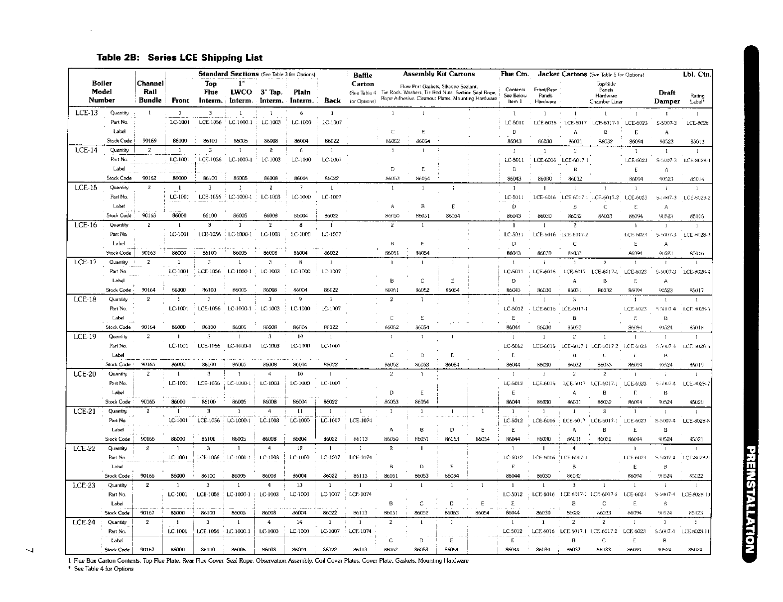
Table 2B: Series LCE Shipping List
][Standard Sections (See Table 3 for Optionsl Barge Assemb]_ Kit Cartons Flue Ctn. Jacket Cartons (s_ Table 5 Io_ Omionsl LbL Ctn.
ITop Std.
Boiler Channel :Top 1" Carton FIo_ P_rt Gas]_ets Silicone Sea_nt, ¢onlents Fmn_Rear Panels
Model J Rail !Flue LWCO 3" Tap, Plain is_*T_bJ.4 T,eRodsWashersTi_RMNu_ S_ckio_S_alRop__ Draft
Numbel" Bundle I FTont I Intern1. ; [nterm. Internl. Interm. iBack for Optmns! R°P_ Adhesive Cleanout Plates, Mounting Hardware I Se e Below Panels H_rdwar_ Ratira_
;Irem lHardware Chamber LLner Damper Label*
LCE-13 i i
LCE-14
C E
86052 i 86054
1 I
D E
_,6()53 86054
LCE 15 1 1 ]
A R E
_6_]5(/ 86051 86054
LCE-16 2 1
Quantitv :1 1 3 1 :1 6 l
Part No LC-103I LCE1056 LC 10C_ 1 LC 1003 i LC 1090 LC 10_37
!
Label I ! i
C_a,_tiW_I 2 [ 1 • 3 ;z6 .:1
ParENo LC.1001 i LCE 1056 LC 1000-I LC 1003 LC 1LY_ LC 1£X)7
Label
Stock Code 90162 86003 86100 86035 86008 86(104 860'22
Quanti_ 2 l 3 1 2 7 1
PaaNo LC-lC_I LCE 1056 LC 100¢ 1 LC 1C¢3 LC I_,F0 LC 1007
i
Labor
Sio,ck Code 90163 _ i 86100 86005 86008 86004 ; 86022
Quanfil,j 2 l ;3 l 2 8 l
F_rt _o LC 1C_I LCE 1056 LC i00_ i LC 1003 kC lOgO LC 1007
Label 4[ ' ,_+
Sto_kCod; l 90163 : 86_0 :86100 '86005 : 86008 ' 86004 [ 86022
I3 1 3 _ i 1
LC-I _)l LCE 1056 LC IO00 l LC 1003 LC 100¢ LC 1007
[ 8600_ 86100 86O35 86008 86O04 86022
3139I
LC.IOD1 LCE.I056 LC I(X_A] I LC 10_33 IC If_O LC 1_07
B E
8_051 8(,,054
1 1LCE-I? Quanlily i 2
Part NO
Label
Sleek Code 90164
LCE 18 Qua_tlt_ 2
Parl No
Label
Stock Code 9016_
LCE 19 Quanmv 2
1
E
86O54
B c
86(151 8_052
2I
c E
86100 86005 8N'_38 86004 86[322 86052 86054
1
LC 5011
DA
86043 86030 F_5_I1
I l 2
LC 5011 LCE 6016 LCE.6017 1
D B
8(_O43 : 86030 86032
I 1 i ]
LC5011 LCE6016 LCE60171 ICE60172
D B C
86043 86030 86032 660_
1 1 2
LC 5011 LCE 6016 LCE 6017 2
D C
86030 85033
i I l 2
LC.5011 LCE.6016 LCE b_17 LCE 6017 1
D A B
86043 86030 86031 86032
1 1 3
LC 5012 LCE 6016 LCE 6017 1
E B
86044 86030 86032
1 1 1 l 1 l
LCE6016 i LCE6OI7 LCE6017 I LCE6023 $50_73 LCES028
B E A
B6032 860q4 q0523 85013
1i1
LCE N)23 S 5007 3 LCE 81328 1
E A
8N194 9052_ 85014
l:l
ICE 6023 6 ,t_17 3 LCE _U2'3 :
E A
86094 90523 85015
II1
LCE 6O23 S fl(x_7 3 LCE _(],_8 3
E A
86094 9(_52:] 8._16
1 E l
LCE 6023 S 5007 3LCE t_02S 4
E A
8_194 90523 _:5017
1 1 1
1CE ()023 % F,O(_7 4 I CE _)2_ 5
E [l
8609,1 9(_524 _5(_1_.
1 3 1 3 10 1 1 ] / l 1 2 1 [
Part No LC.1001 LCE 1056 I.C 1000 I [ C 1003 [C 1000 LC 1007 LC r_12 LCE 6016 LCE 6017 I [ CE [)(117 2I CK 602_
Label C D E E B C K
Stuck Code 90165 86030 86107 86N/5 86008 825004 86022 86052 86053 86054 86044 8€1130 86032 86ql3 86094
i
LCE-20 Q_a_iW z i ;! 1 4I0 I z I 1 I 2z
i i
P_rlNo LCI00I LCEI056 LCI0_I LCI003 LCIOGO LCI007 LC.5012 LCE6016 I.CENII7 lCEbOlTl LCE6023
1
e _ :Lal_l I , _I 'o_,_ '[/ D E E A B E
otc_k _c&, 9(1165 86000 100 _ 8N)08 _ 86022 86053 86054 86044 86o:m 86o31 86o32 _6c,'94
LCE-21 Quantil_ 2 . l J 3,1 .q[ II L } l l 1 ] ,1 l _1 1 1 3 ]
PartNo LC.I(_I i LCE1056 LC-1000-1 LCl003 LC-10C_ l LCI0_7 LCEI074 LC5012 LCE6OI6 LCE6017 LCE6OITI LCE_323
La_, _ ' _. __ : t l:A B D E E A B E
S_o_kCo& I9O166 _ 8610_ I _5 ! 86o¢8 86oo4 86o22 _ _113 P,6_35o 86_51 86o53 86O54 8,5O44 86O30 86O31 86032 86094
I
LCE-22 Quantity [ 2 1 314, 12 1 1 21 1 11 I 4I
i]LCE1o56+LC :c_]:; ! LCI0_3 [ LCI000 "LCI007 LCE1074 LC5012 LCE6OI6 'LCE6OI71 LCE6023
Part No LC 1(1131
Label _ B D E E B [2
Stc<k Code 90166 NNI00 _ 86100 86005 86908 86004 i 86022 86113 86051 8605,3 86054 86044 86030 86032 86094
LCE 23 Quantity 2131 4 13 l 1 1 1 1 1 1 1 1 3 1 1
i
ParlN° iLC'IC_)I LCE1056 I LC-I0001 LCI(X)3 LC.10,P_ iLC-1007 [CE-1074 I.C5012 LCE6016 ICE6OlT] 1CE60172 I.CE6021
iD E E B C E
Slake _ 86100 86035 l 86038 86004 ! 86022 8,5113 86051 86052 860,_,3 g,5_54 8,5044 86030 861132 86033 b_5094
i
Qu_n_W I2] ; 3]!4 14 l :2l:]l2z i
LCE-24 PartNo. I l Lci001 ]LCEI056 :LC10_)I I LC-1003 LC-IO00' LC-1007 LEE-1074 i [
l [ :, _] i-- DIE _ i LC 5012 LCE 6016 LCE 0017 i "CE 6017 2 LCE 6023
L_: I,c i E B C E
1 Flue Box Cm'lon C_ntent_: Top Flue Plate, P,enr Hue Cover, Seal Rope, Observalion Assemblp, Coil Couer Plates, Cover Plate, Gaskets, Mounting Hardware
] ]
_, 51_J7 4 tCE ,_028 r
B
,Blf124 NS[llq
]
6,(HJ7 4 LCE _()2g ]
B
9q524 g5o20
I I
S 5007 4 LCE 8028
B
q0524 85021
1 1
S 5(,_}7 4 [CE MI]2_ (
B
_]524 g5022
;[
-, _,1_7 4 LCESOZB ](
R
9O524 85O23
]!
S o0_17 4 LCE<_02_ 1 ]
B
9t_24 K5024
*See Table 4 for Options
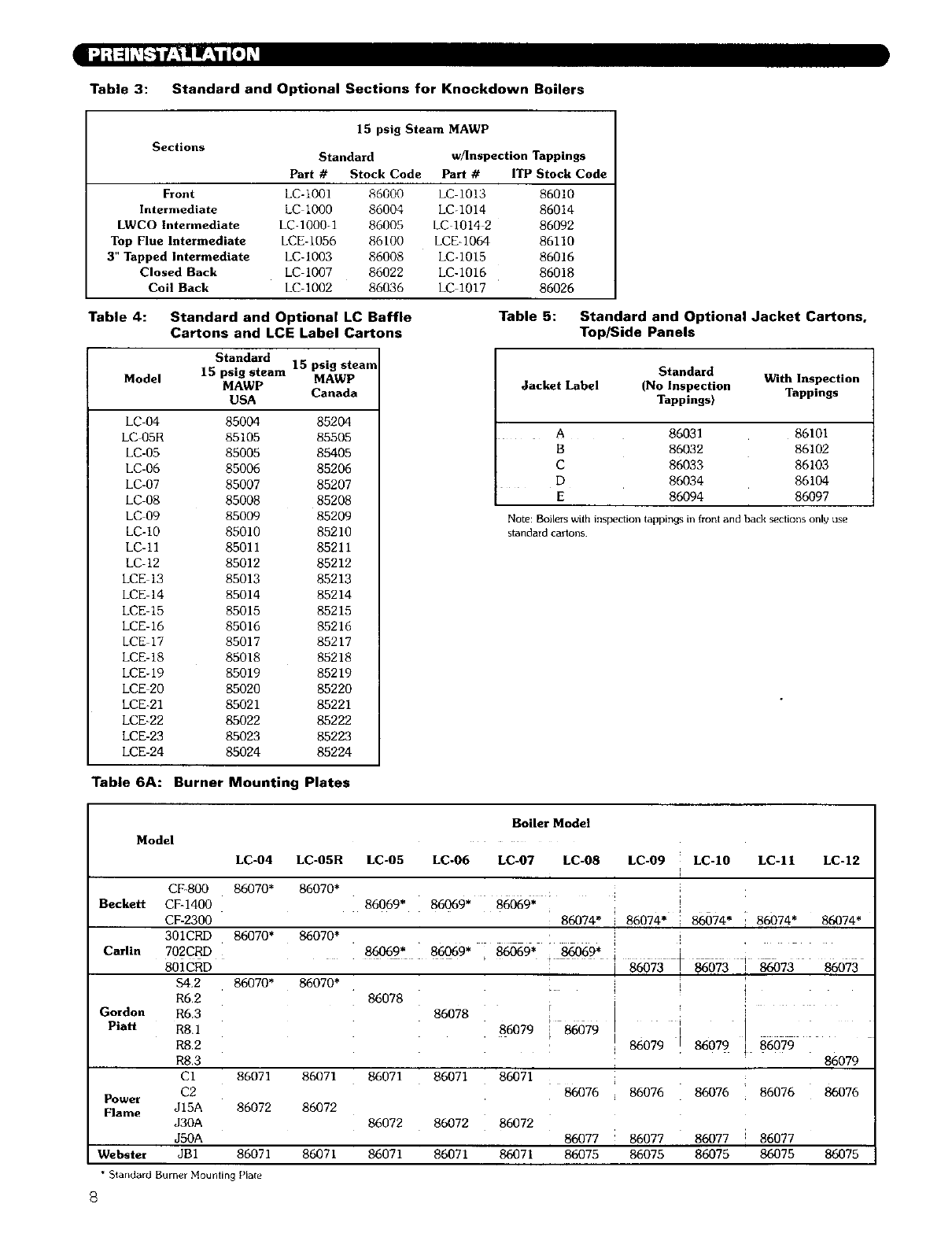
Table 3: Standard and Optional Sections for Knockdown Boilers
Sections
15 psig Steam MAWP
Standard
Part #Stock Code
Front LC-1001 86000
Intermediate LC 1000 86004
LWCO Intermediate LC-IO00-1 86008
Top Flue Intermediate LCE-1056 86100
3" Tapped Intermediate LC-1003 86008
Closed Back LC 1007 86022
Coil Back LC- 1002 86036
wflnspectionTappings
Pad #ITPStock Code
LC 1013 86010
LC-IO14 86014
LC 1014 286092
LCE-1064 86110
LC-1015 86016
LC-1016 86018
LC 1017 86026
Table 4: Standard and Optional LC Baffle
Cartons and LCE Label Cartons
Standard 15 psig steam
Model 15 psig steam MAWP
MAWP Canada
USA
LC-04 85004 85204
LC05R 85105 85505
LC-05 85005 85405
LC-06 85006 85206
LC-07 85007 85207
LC-08 85008 85208
LC 09 85009 85209
LC-10 85010 85210
LC-I1 85011 85211
LC-12 85012 85212
LCE 13 85013 85213
LCE 14 85014 85214
LCE 15 85015 85215
LCE-16 85016 85216
LCE 17 85017 85217
LCE-18 85018 85218
LCE-19 85019 85219
LCE 20 85020 85220
LCE-21 85021 85221
LCE-22 85022 85222
LCE-23 85023 85223
LCE-24 85024 85224
Table 5: Standard and Optional Jacket Cartons,
Top/Side Panels
Standard
Jacket Label (No Inspection With Inspection
Tappings) Tappings
A 86031 86101
B 86032 86102
C 86033 86103
D 86034 86104
E 86094 86097
Note: Boilem with inspection tappings in front and back sections only use
s_ndard ca_ons.
Table 6A: Burner Mounting Plates
Boiler Model
Model
LC-04 LC-05R LC-05 LC-06 LC-07 LC-08 LC-09 LC-10 LC-11 LC-12
86070*
Beckett 86069* 86069* 86069*
86074" 86074" 86674* i 86074* 86074*
! i
C_li. 86o69* _69. i ;i
(Jordon
Piatt
86070*
86070* 86070*
86070* 86070*
CF-800
CF-1400
CF-2300
301CRD
702CRD
801CRD
$4.2
R6,2
R6.3
R8.1
R8.2
R8,3
CI
C2
JI5A
J30A
J50A
JBI
T
i
i 86079
86069* 86069*
86078
86078
86071 86071
86072 86072
86079
86071
86072
86071
[
I
86079 [86079 86079
86079
86076 86076
86071 86071
Power 86076 86076 86076
Flame 86072 86072
86077 86077 86077 86077
Webster 86071 86071 86071 86071 86075 86075 86075 86075 86075
* Standard Burner Mounting Plate
{3
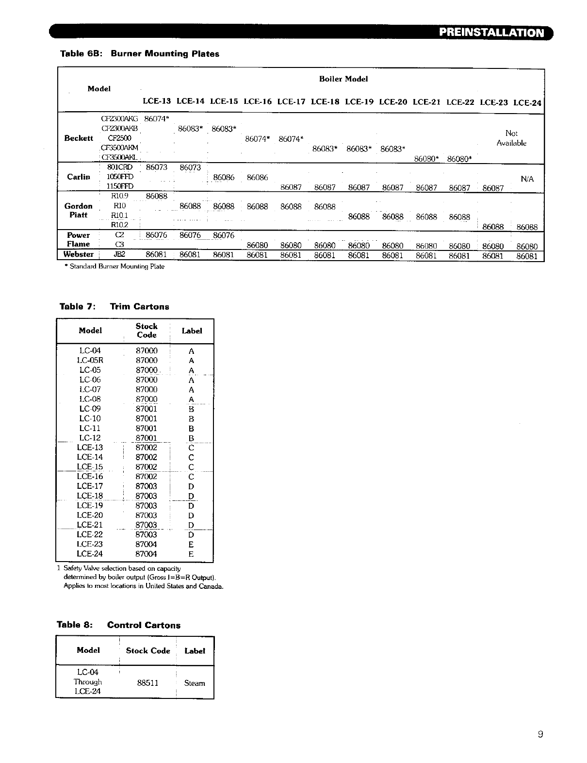
Table 6B: Burner Mounting Plates
Boiler Model
Model
LCE-13 LCE-14 LCE-15 LCE-16 LCE-17 LCE-18 LCE-19 LCE-20 LCE-21 LCE-22 LCE-23 LCE-2
CF2300AKG 86074*
CF2300AKB 86083* 86083* Not
Beckeit CF2500 86074* 86074* Available
CF35(K)ARM 86083* 86083* 86083*
CF3500PJKL 86080* 86080*
80ICRD 86073 86073
Carlin 1050FFD . 86086 86086 N/A
I150FFD 86087 86087 86087 86087 86087 86087 86087
R10.9 86088
Gordon R10 86088 86088 86088 86088 86088
Plait R10.1 86088 86088 86088 86088
R102 86088 86088
Power C2 86076 86076 86076
Flame C3 86080 86080 86080 86080 86080 86080 86080 86080 86080
Webster JB2 86081 86081 86081 86081 86081 86081 86081 86081 86081 86081 86081 86081
*Standard Burner Mounting Plate
Table 7: Trim Cartons
Model Stock
Code Label
LC-04
LC-05R
LC-05
LC 06
LC-07
LC-08
LC 09
LC-10
LC-11
LC-12
LCE-13
LCE-14
87000 A
87000 A
87000 A
87O00 A
87000 A
87000 A
87001 B
87001 B
87001 B
87001 B
87002 C
87002 C
LCE-15 87002 C
LCE-16 87002 C
LCE-17 87003 D
LCE-18 _ 87003 D
LCE-19 87003 D
LCE-20 87003 D
LCE-21 _ 87003 D
LCEo22 87003 D
LCE-23 87004 E
LCE-24 87004 E
1 Safety Valve selection based on capacity
determined by boiler output (Gross I=B=R Output).
Applies to most locations in United States and Canada.
Table 8: Control Cartons
!
Model Stock Code Label
LC-04
Through 88511 Steam
LCE-24
9
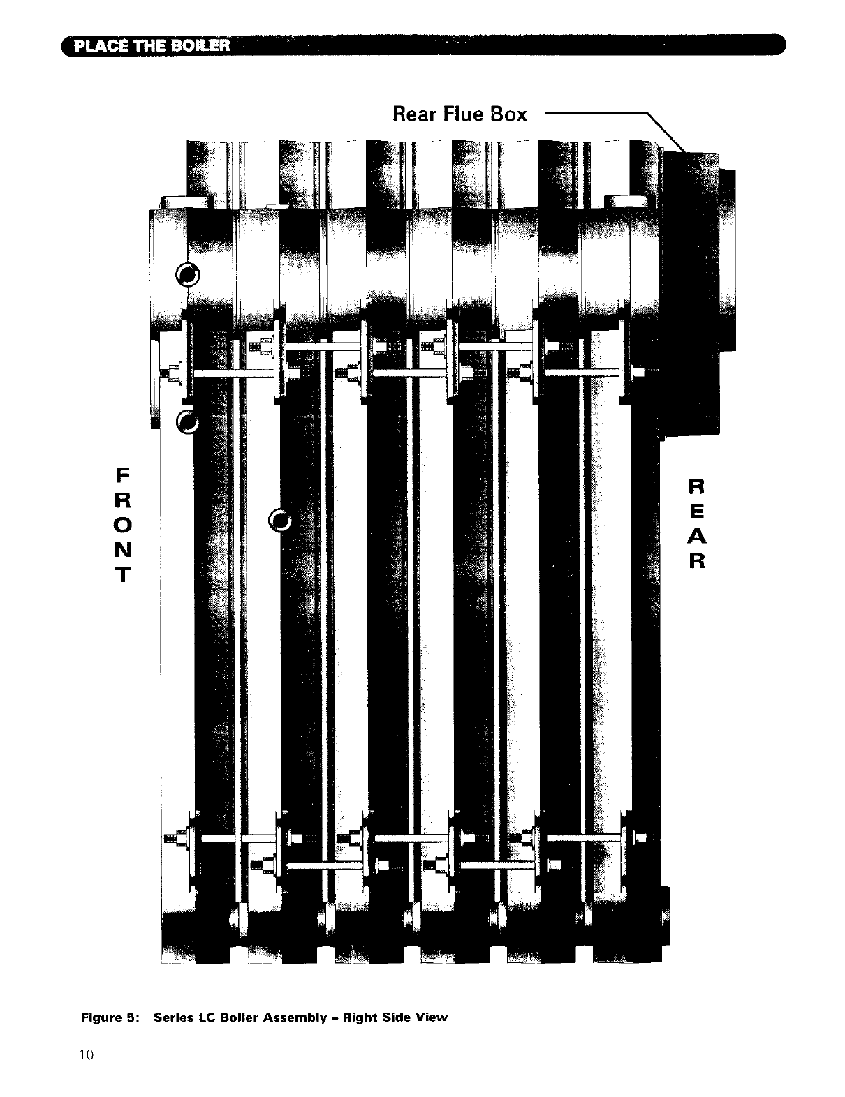
Rear Flue Box
F
R
0
N
T
R
E
A
R
Figure 5: Series LC Boiler Assembly - Right Side View
10
=3'
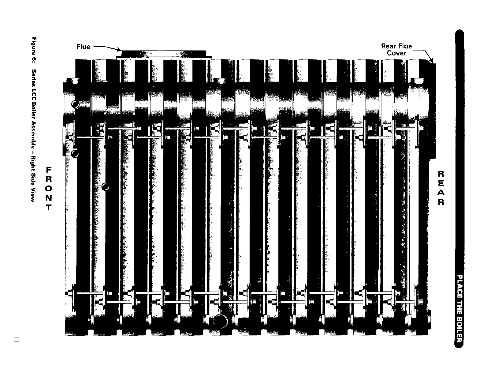
€Flue Rear Flue
Cover
®
(4
r-
i11
m
o_,
,,R
>
f_
O"
I
FR
_: R E
< o A
N R
T
_I 1:,.',_'_€,.][9_,'_€"1:=1,_]i:{*]llq_:
1. Remove crate top and sides. Remove any loose
cartons. Remove burner support pedestal and
nipple, if supplied.
2. Lift boiler off crate pallet. Move to location
determined in Chapter I: Preinstallation.
3. Remove lifting frame and hardware.
4. Re-install burner support pedestal and nipple if
necessary.
5. Proceed to Chapter 3: Piping the Boiler.
[,.)q 114i_[.I1,,][4mlmlh_lk'_li=(,,]l!_:
I:_N V;l.$'I_vJI:]l_.) :]I[.lN[4I:{o]II::i-"
i. Move block to location determined in Chapter I:
Preinstallation.
2. Remove lifting frame and hardware.
3. Proceed to Section D: Install Coils or PLates
].
2.
3.
4.
Place channel rails as shown in Figure 4.
Open the Section Assembly Kit cartons. These
cartons contain the parts needed for assembly of the
sections.
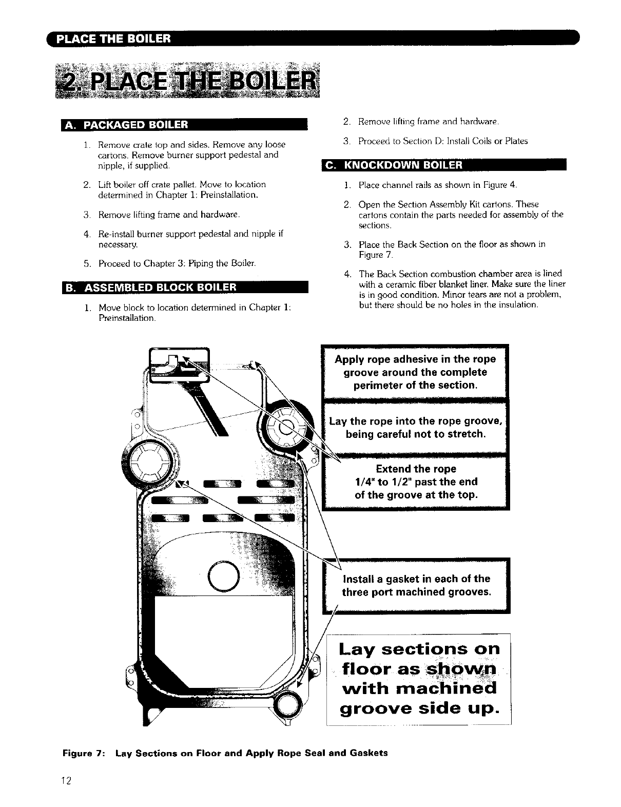
Place the Back Section on the floor as shown in
Figure 7.
The Back Section combustion chamber area is lined
with a ceramic fiber blanket liner. Make sure the liner
is in good condition. Minor tears are not a problem,
but there should be no holes in the insulation.
Lay sections on
floor as SohOw
with maChined
groove side up. i
Figure 7: Lay Sections on Floor and Apply Rope Seal and Gaskets
12
Flat'_
Machined
o?:eoJi
i.°°°2°
Flow Port
Gasket
Recess
Machined
Face
\.
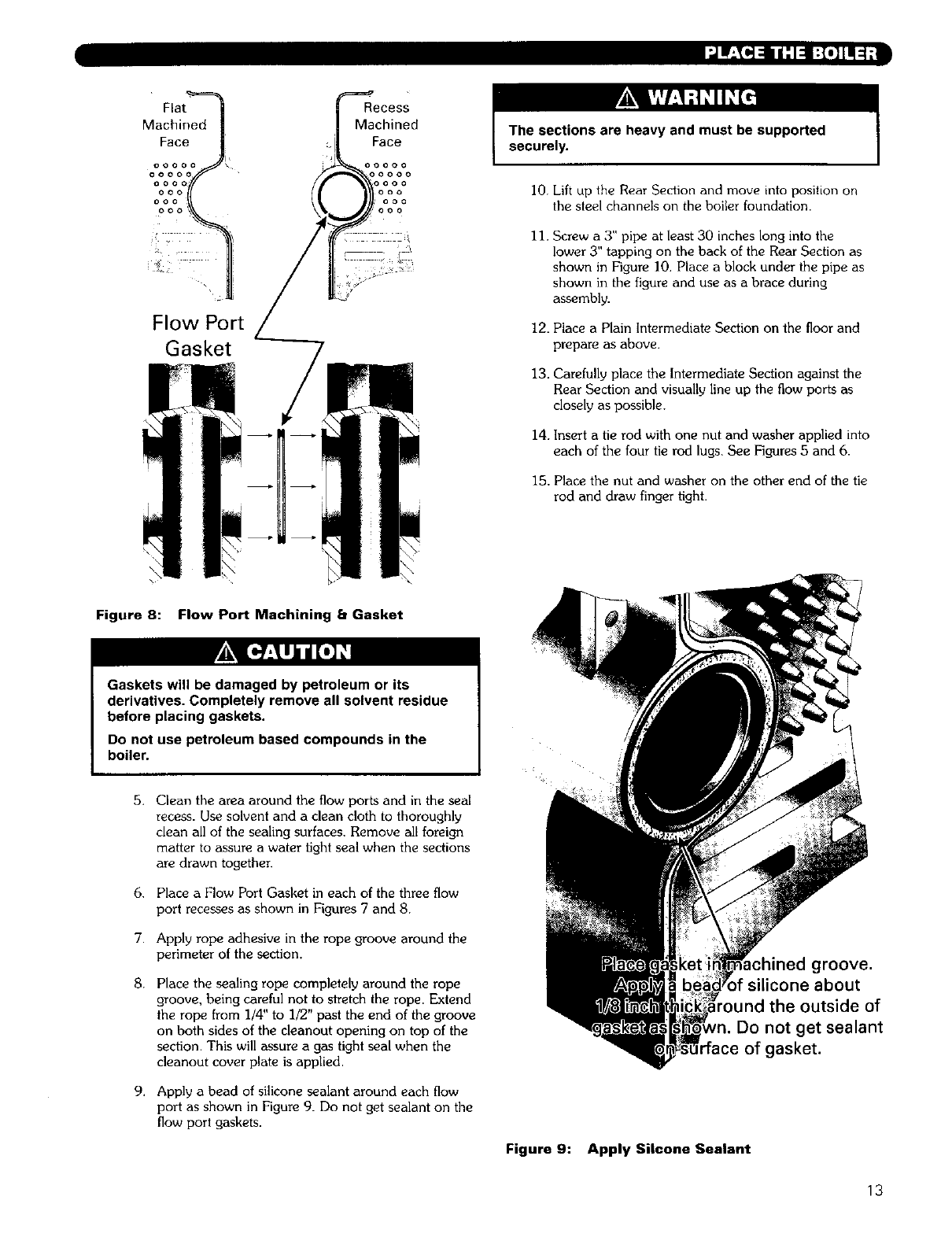
Figure 8:
\
\
Flow Port Machining bGasket
The sections are heavy and must be supported
securely.
I0. Lift up the Rear Section and move into position on
the steel channels on the boiler foundation.
11. Screw a 3" pipe at least 30 inches long into the
lower 3" tapping on the back of the Rear Section as
shown in Figure I0. Place a block under the pipe as
shown in the figure and use as a brace during
assembly.
12. Place a Plain Intermediate Section on the floor and
prepare as above.
13. Carefully place the Intermediate Section against the
Rear Section and visually line up the flow ports as
closely as possible.
14. Insert a tie rod with one nut and washer applied into
each of the four tie rod lugs. See Figures 5 and 6.
15. Place the nut and washer on the other end of the tie
rod and draw finger light.
Gaskets will be damaged by petroleum or its
derivatives. Completely remove all solvent residue
before placing gaskets.
Do not use petroleum based compounds in the
boiler.
5.
6.
7.
8.
9,
Clean the area around the flow ports and in the seal
recess. Use solvent and a clean cloth to thoroughly
clean all of the sealing surfaces. Remove all foreign
matter to assure a water fight seal when the sections
are drawn together.
Place a Flow Port Gasket in each of the three flow
port recesses as shown in Figures 7 and 8.
Apply rope adhesive in the rope groove around the
perimeter of the section.
Place the sealing rope completely around the rope
groove, being careful not to stTetch the rope. Extend
the rope from 1/4" to 1/2" past the end of the groove
on both sides of the cleanout opening on top of the
section. This will assure a gas tight seal when the
cleanout cover plate is applied.
Apply a bead of silicone sealant around each flow
port as shown in Figure 9. Do not get sealant on the
flow port gaskets.
Figure 9:
chined groove.
silicone about
ide of
Do not get sealant
"face of gasket.
Apply Silcone Sealant
13
SECTIONS ARE TOP HEAVY.
HANDLE WITH CARE TO
AVOID TIPPING OR FALLING.
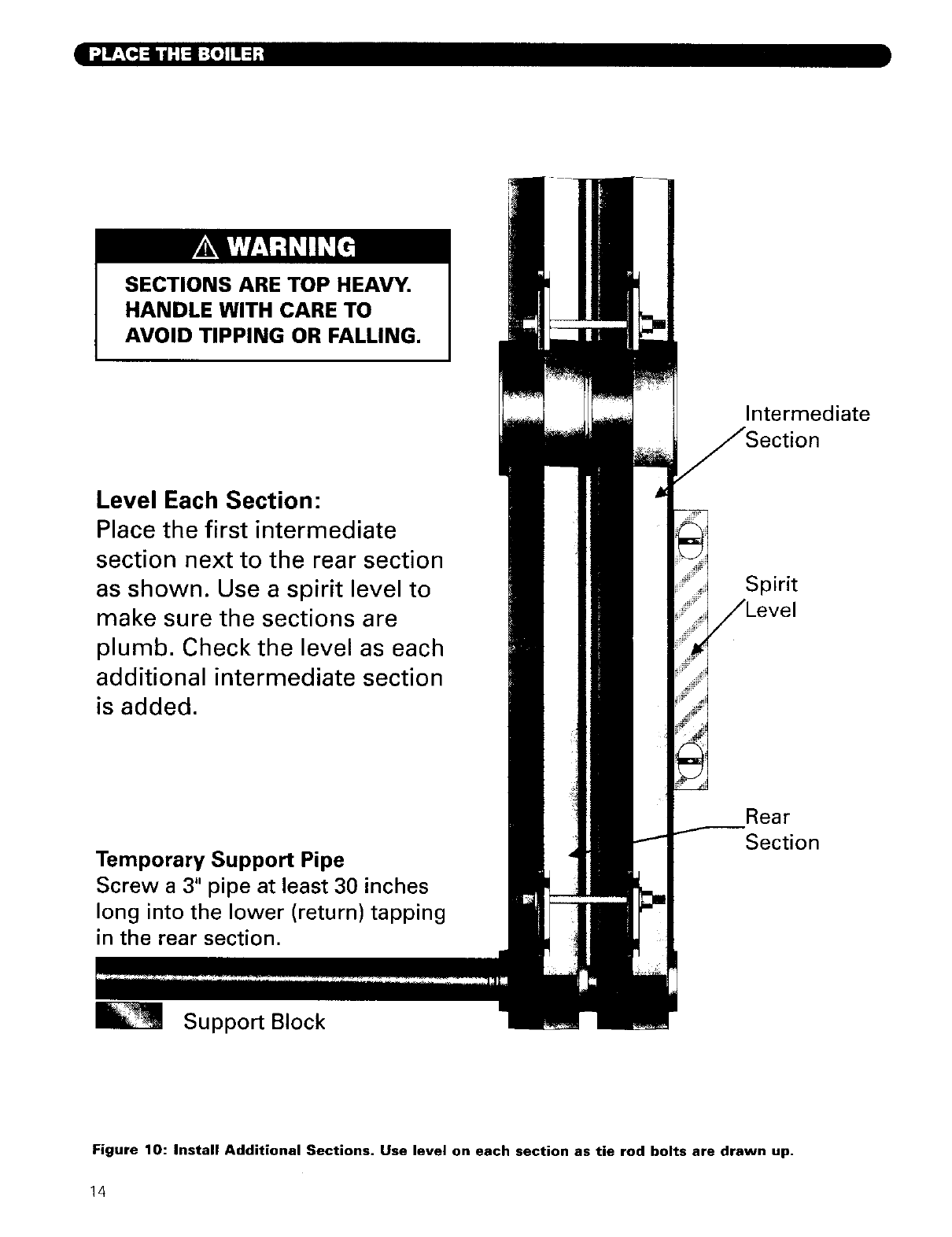
Level Each Section:
Place the first intermediate
section next to the rear section
as shown. Use a spirit level to
make sure the sections are
plumb. Check the level as each
additional intermediate section
is added.
Temporary Support Pipe
Screw a 3" pipe at least 30 inches
long into the lower (return) tapping
in the rear section.
Support Block
Intermediate
tion
Spirit
.=vel
Rear
Section
Figure 10: Install Additional Sections. Use level on each section as tie rod bolts are drawn up.
14
I "]av_..]_ ii'l_ [:7_]TI :I;1
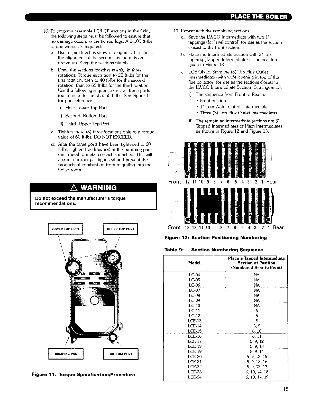
16. To propedy assemble LC/LCE sections in the field.
the following steps must be followed to ensure that
no damage occurs to the tie rod lugs. A 0-I00 ftdbs
torque wrench is required•
a, Use a spirit level as shown in Figure I0 to check
the alignment of the sections as the nuts are
drawn up Keep the sections plumb•
b. Draw the sections together evenly, in three
rotations. Torque each port to 20 ft-lbs for the
first rotation, then to 40 ftdbs for the second
rotation, then to 60 ft-lbs for the third rotation
Use the following sequence until all three ports
touch metal-to-metal at 60 ft-lbs. See Figure 11
for port reference
i) First: Lower Top Port
ii) Second: BO_LOmPort
iii) Third: Upper Top Port
c. Tighten these (3) three locations only to a torque
value of 60 ft-lbs. DO NOT EXCEED.
d. After the three ports have been tightened to 60
ft-lbs, tighten the draw rod at the bumping pads
until metal-to-metal contact is reached. This will
assure a proper gas tight seal and prevent the
products of combustion from migrating into the
boiler room.
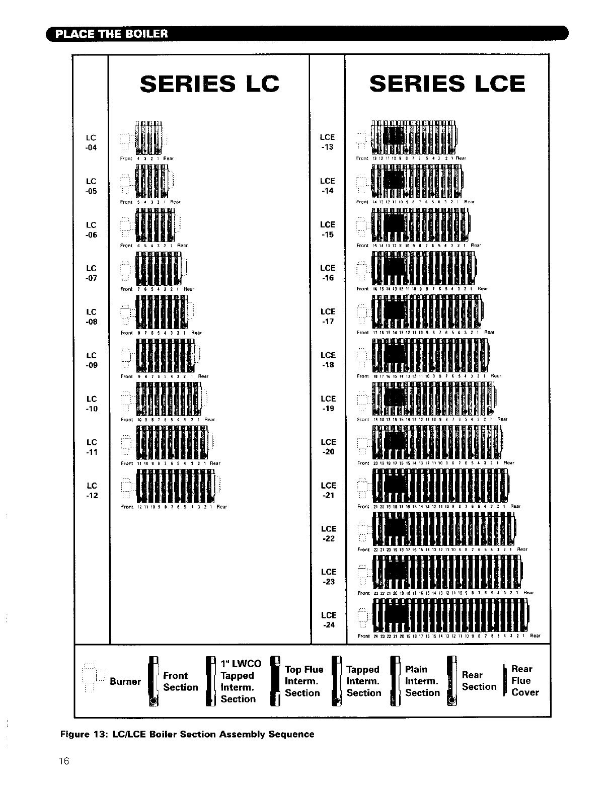
17 Repeat with the remaining sections.
a. Save the LWCO Intermediate with two I"
tappings (for level control) for use as the section
closest to the front section.
b. Place the Intermediate Section with 3" top
tapping (Tapped Intermediate) in the position
given in Figure 13
C, LCE ONLY. Save the (3) Top Flue Outlet
Intermediates (with wide opening in top of the
flue collector) for use as the sections closest to
the LWCO Intermediate Section• See Figure 13.
The sequence from Front to Rear is:
• Front Section
• I" Low Water Cut-off Intermediate
• Three (3) Top Flue Outlet Intermediates
it) The remaining intermediate sections are 3"
Tapped Intermediates or Plain Intermediates
as shown in Figure 12 and Figure 13.
Front 12 11 10 9 8 7 6 5 4 3 2 1 Rear
Do not exceed the manufacturer's torque
recommendations.
,LOWER TOP PORT I UPPER TOP PORT I
/
I
/
i ouMP,.OP.Oi I +ooPO.TI
Figure 11: Torque Specification/Procedure
iiiii
Front 13 12 11 10 9876 5 4321 Rear
Figure 12: Section Positioning Numbering
Table 9: Section Numbering Sequence
Place a Tapped Intermediate
Model Section at Position
(Numbered Rear to Front)
LC-04 NA
LC-05 NA
LC-06 NA
LC-07 NA
LC-08 NA
LC-09 NA
LC-10 NA
LC-II 6
LC-12 6
LCE-14 5, 9
LCE-15 . 6, I0
LCE-16 6, II
LCE-17 5, 9, 12
LCE-18 5, 9, 13
LCE-19 5, 9, 14
LCE-20 5, 9, 12, 15
LCE-21 5, 9, 13, 16
LCE-22 5, 9, 13, 17
LCE-23 6, I0, 14, 18
LCE-24 6, I0, 14, 19
15
l_nP_j :I=II_[o_
SERIES LC SERIES LCE
LC
-04
LC
-05
LC
-06
LC
-07
LC
-08
LC
-09
/C
-10
LC
-11
LC
-12
Fron_ 43 Z I Aear
Front 5 4 3 Z IRear
Front eS4321Rear
Front 876_ 4 3 2 I Rear
Front _ s76 5 4 3 2_Rear
Front 10 9 S 7 6 54_2I Rear
Front II Io 9_765 4 3 2 I Rear
Fron_ Iz II 10 9 e 7E64_2IRear
LCE
-13
LCE
-14
LCE
-15
LCE
-16
LCE
-17
LCE
-18
LCE
-19
LCE
-20
LCE
-21
LCE
-22
LCE
-23
LCE
-24
Front 13 IZ H 10 9 e _ 6 5 4 3 _ _ Rear
iiill
iiii
Fro_t _ I_ 13 12 _1 _0 9 n 7 6 5_3 Z I Rea_
Fron_ 16 15 _ I_ 1_ _1 _0 9 a _5_4s2qR_ar
iiill
Fro_ 19 I_ I_ _4 13 _2 I_ 10 g e 7 65 4 _ZIRear
Front I$ I_ 16 16 14 13 12 II 10 9 B 7 664 3 Z I _e_r
Front 19 19 17 IS 15 14 13 12 II 10 9 6 7 654 32T Rear
Front N 19 19 17 IB 15 14 I_ II I) I_ _ _ 1 _ _ I I l I Ftear
Fron_ zl _1 19 18 I_ _1_ 15 14 _Z _2 II l0 9 S _664 3 2 I Rear
_ront z2 Zl 2O 19 le I_ _1_ 15 14 13 _2 II _0 9S ?_ 6 4 3 Z IRear
Front Z3 _Zl _1 19 _19 15 16 14 _ 12 II 10 9B _ e_ _ 32_Rear
'! i
1" LWCO Top Flue
i i Front Tapped Interm.
,_ Burner Section _Interm. Section
I Section
_j Rear
Tapped Plain Rear Flue
Interm. Interm. Section
Section I Section _Cover
Figure 13: LC/LCE Boiler Section Assembly Sequence
16
III:(_i i/.l-, :_']f!_"
JR ILl'_[_ Ir'.._UHNIl{_o]lNl_,,_[o];| I_IIF,.._IUI:::F_ =I lii'i.];{o]_lL'l|[@/1511/II1:1.]1111
1+
2.
3.
4.
5.
6,
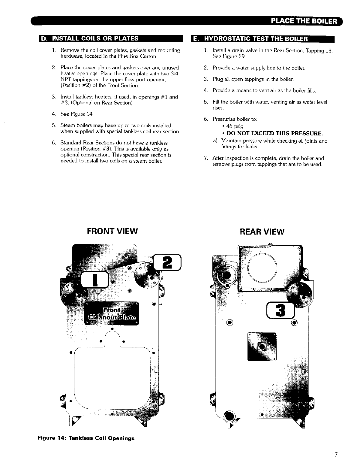
Remove the coil cover plates, gaskets and mounting
hardware, located in the Flue Box Carton•
Place the cover plates and gaskets over any unused
heater openings• Place the cover plate with two 3/4"
NPT tappings on the upper flow port opening
(Position #2) of the Front Section•
Install tankless heaters, if used, in openings #i and
#3, (Optional on Rear Section)
See Figure 14
Steam boilers may have up to two coils installed
when supplied with special tankless coil rear section•
Standard Rear Sections do not have a tankless
opening (Position #3). This is available only as
optional constroction. This special rear section is
needed to install two coils on a steam boiler
1. Install a drain valve in the Rear Section, Tapping 13
See Figure 29.
2. Provide a water supply line to the boiler
3. Plug all open tappings in the boiler
4. Provide a means to vent air as the boiler fills.
5. Fill the boiler with water, venting air as water level
rises.
6. Pressurize boiler to:
• 45 psig
•DO NOT EXCEED THIS PRESSURE.
a) Maintain pressure while checking all joints and
fittings for leaks•
7. After inspection is complete, drain the boiler and
remove plugs from tappings that are to be used.
FRONT VIEW REAR VIEW
Figure 14: Tankless Coil Openings
17
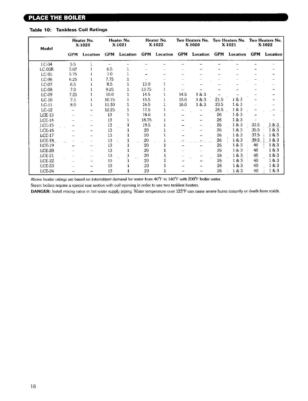
Table 10: Taokless Coil Ratings
Heater No. Heater No. Heater No. Two Heaters No. Two Heaters No. Two Heaters No.
X-1020 X-1021 X-1022 X-1020 X-1021 X-1022
Model
GPM Location GPM Location GPM Location GPM Location GPM Location GPM Location
LC-04 5 5 I
LC_05R 562 i 65
LC 05 575 I 70
LC-06 6.25 I 7.75
LC-07 6.5 i 8.5
LC-08 7.0 I 9.25
LC-09 7.25 i 10.0
LC_10 75 i 10.75
LC-11 8.0 I 11.50
LC-12 12.25
LCE 13 13
LCE-14 13
LCE-15 13
LCE-16 13
LCE-17 13
LCE-18 13
LCE-19 13
LCE-20 13
LCE 21 13
LCE 22 - 13
LCE-23 - 13
LCE-24 - 13
i
1
1
1 130 I
I 1375 I -
1 145 i 14.5 I & 3
I 15.5 i 15.0 I & 3 21.5
1 16.5 i 16.0 1 & 3 23.5
I 17.5 I - 24.5
I 18.0 1 - 26
I 18.75 1 - 26
I 19.5 I - 26
I 20 I 26
I 20 I 26
1 20 I . 26
I 20 I 26
1 20 I 26
i 20 I 26
1 20 I 26
1 20 I 26
I 20 1 26
1&3
I&3
1&3
I&3
1&3
1&3
1&3
1&3
l&3
1&3
1&3 :
I&3
I&3
l&3
1&3
33.5 i & 3
35.5 1 & 3
37.5 1 & 3
39.5 t I&3
40 1&3
40 l&3
40 l&3
40 I & 3
40 1 &3
40 1 &3
Above heater ratings are based on intermittent demand for water from 40°F to 140°F with 200°F boiler water.
Steam boilers require a special rear section with col! opening in order to use two tankless heaters.
DANGER: Install mixing valve in hot water supply piping, Water temperature over 125°F can cause severe burns instantly or death from scalds.
18
I_I'_"]51k117=I .l.l_.]Ir:l_
;IN r±_'.l;,,lN_"ie,]il_±_L_[olnnluu_e_v,a:l;_I'.lW'.._und=l',
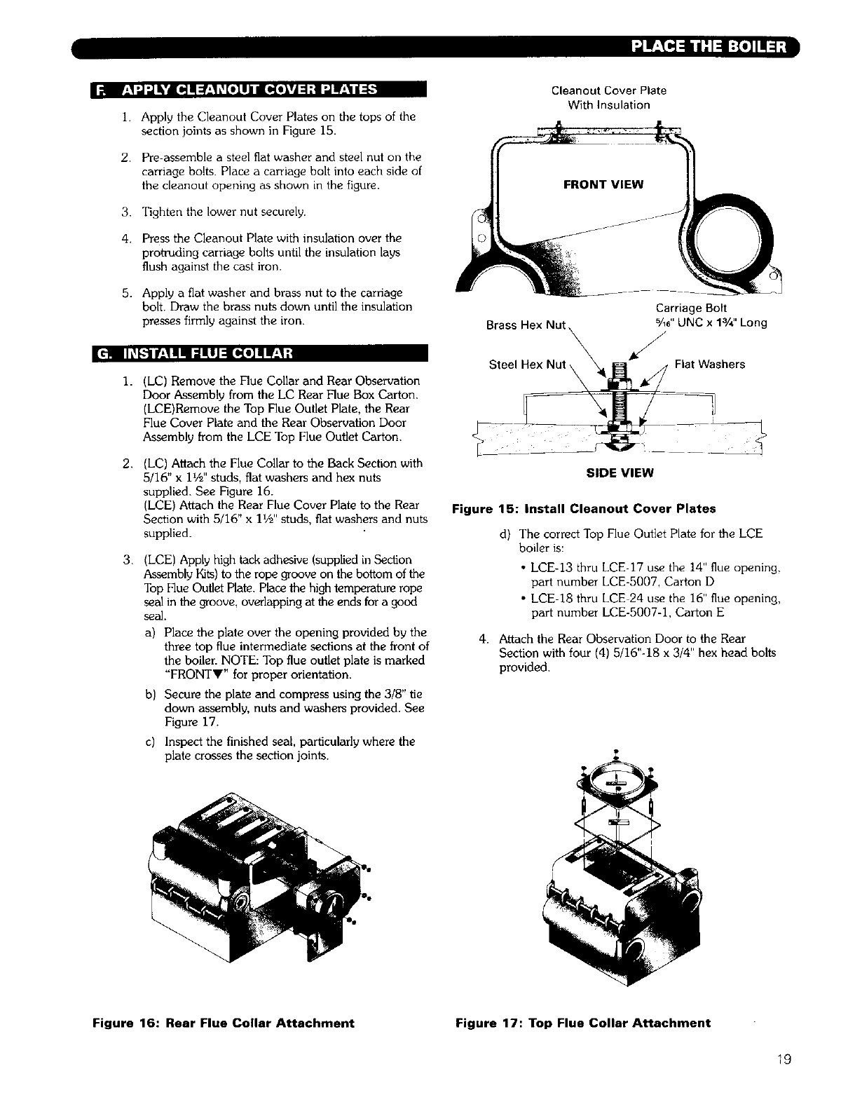
I. Apply the Cleanout Cover Plates on the tops of the
section joints as shown in Figure 15.
2. Pre-assemble a steel fiat washer and steel nut on the
carriage bolts. Place a carriage bolt into each side of
the cleanout opening as shown in the figure.
3. Tighten the lower nut securely.
4. Press the Cleanout Plate with insulation over the
protruding carriage bolts until the insulation lays
flush against the cast iron.
5. Apply a fiat washer and brass nut to the carriage
bolt. Draw the brass nuts down until the insulation
presses firmly against the iron.
1.
2.
3.
(LC) Remove the Flue Collar and Rear Observation
Door Assembly from the LC Rear Flue Box Carton.
(LCE)Remove the Top Flue Outlet Plate. the Rear
Flue Cover Plate and the Rear Observation Door
Assembly from the LCE Top Flue Outlet Carton.
(LC) Attach the Flue Collar to the Back Section with
5/16" x 11/2'' studs, fiat washers and hex nuts
supplied. See Figure 16.
(LCE) Attach the Rear Flue Cover Plate to the Rear
Section with 5/16" x 1172'' studs, fiat washers and nuts
supplied.
(LCE) Apply high tack adhesive (supplied in Section
Assembly Kits) to the rope groove on the bottom of the
Top Flue Outlet Plate. Place the high temperature rope
seal in the groove, overlapping at the ends for a good
seal.
a) Place the plate over the opening provided by the
three top flue intermediate sections at the front of
the boiler. NOTE: Top flue outlet plate is marked
"FRONTV" for proper orientation.
b) Secure the plate and compress using the 3/8" tie
down assembly, nuts and washers provided. See
Figure 17.
c) Inspect the finished seal, particularly where the
plate crosses the section joints.
Cleanout Cover Plate
With Insulation
Carriage Bolt
Brass %6" UNC x 13/4'' Long
/
J
Steel Hex Nut _ Flat Washers
\
SIDE VIEW
Figure 15: Install Cleanout Cover Plates
d) The correct Top Flue Outlet Plate for the LCE
boiler is:
• LCE-13 thru LCE 17 use the 14" flue opening,
part number LCE-5007, Carton D
• LCE-18 thru LCE 24 use the 16" flue opening,
part number LCE-5007-1, Carton E
4. Attach the Rear Observation Door to the Rear
Section with four (4) 5/16"-18 x 3/4" hex head bolts
provided.
Figure 16: Rear Flue Collar Attachment Figure 17: Top Flue Collar Attachment
19
II: _h__'_ ir_,_tlm etUJ ::It:f_,!-t;l l:_
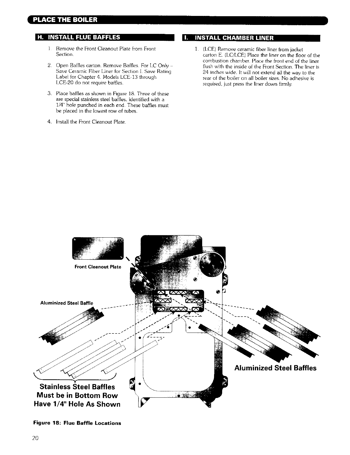
1 Remove the Front Cleanout Plate from Front
Section.
2.
3.
Open Baffles carton Remove Baffles. For LC Only -
Save Ceramic Fiber Liner for Section I Save Rating
Label for Chapter 4. Models LCE 13 through
LCE-20 do not require baffles
Place baffles as shown in Figure 18. Three of these
are special stainless steel baffles, identified with a
i/4" hole punched in each end These baffles must
be placed in the lowest row of tubes.
4. Install the Front Cleanout Plate.
ii _h,_F:-IIf:'_ I!ql_ :F,__/_I:] ::h| III i'll_i
1. (LCE) Remove ceramic fiber liner from jacket
carton E. (LC/LCE) Place the liner on the floor of the
combustion chamber, Place the front end of the liner
flush with the inside of the Front Section. The liner is
24 inches wide, It will not extend all the way to the
rear of the boiler on all boiler sizes. No adhesive is
required, just press the liner down firmly.
Front Cleanout Plate
Aluminized Steel Baffle
Aluminized Steel Baffles
Stainless Steel Baffles
Must be in Bottom Row
Have 1/4" Hole As Shown
Figure 18: Flue Baffle Locations
2O
,m ;,]1fl::1i_ :1:1:1_,]]1[_-
_! IiI; t _1",I:I -'!:!1/ [*] L_
i. The boiler must be pressure tested as outlined in the
chapter "Place the Boiler Sections" of this manual.
2. The Supply and Return piping can be installed
before the jacket is applied. Use nipples long enough
to extend through the jacket.
;N t-"llll,,ll, lli'd I:,ll:JIL_[€
1.
2.
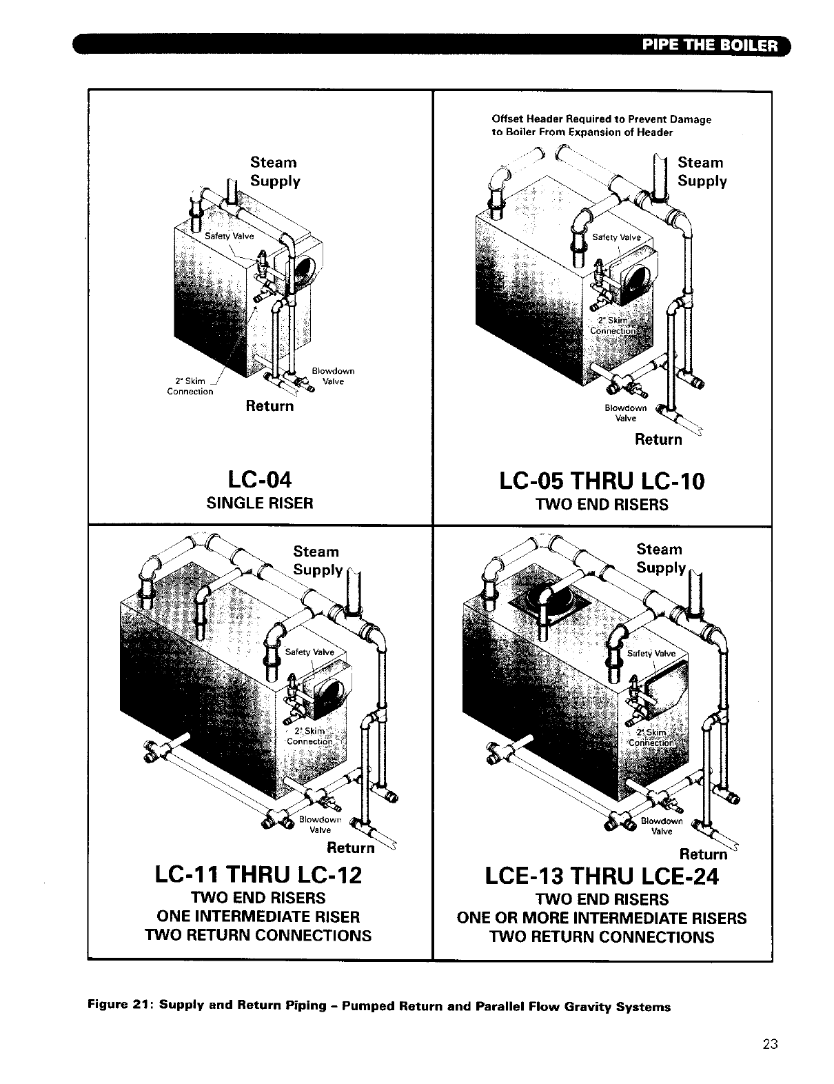
See Figure 21 for piping illustration.
Install Top connections sized per Table 11.
a) Model LC-04 requires one riser off the Rear
Section. Plug the 4" tapping in the top of the
Front Section.
b) Models LC-05 through LC-10 require two risers,
one off the Front and one off the Rear Section.
c) Models LC-11 and LC-12 require three risers,
one each off the Front and Rear Sections plus
one off the Tapped Intermediate Section.
d) LCE models require three or more risers.
5,
6.
7.
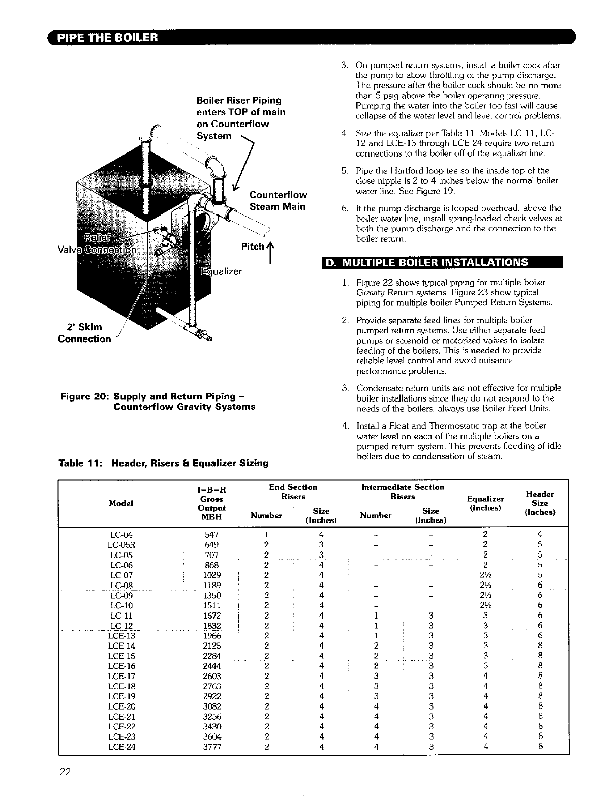
Counterflow Gravity systems require the boiler steam
line to enter the top of the steam main. See
Figure 20 for this special case.
Do not reduce the size or number of risers
shown. These are required for reliable operation of
the boiler. If the risers are undersized or incorrectly
placed, a sloped water line can occur in the boiler,
causing possible overheating of some sections.
Pipe the Header with an offset as shown in the
drawings. This offset prevents the expansion and
contraction of the Header from damaging the boiler
sections.
8.
9.
Always locate the Steam Supply take-off
between the Equalizer and the last Boiler
Riser. (See Peerless Heater Company's "Steam
Installation Survey" for discussion). Locating the
steam supply between the risers will cause water
carryover to the system.
Do not use a bull head tee to provide steam supply
and equalizer connections, this will cause water level
bounce and carryover.
Jel! I it 11ill ltl'_l fJI iI h:_lc
3.
4.
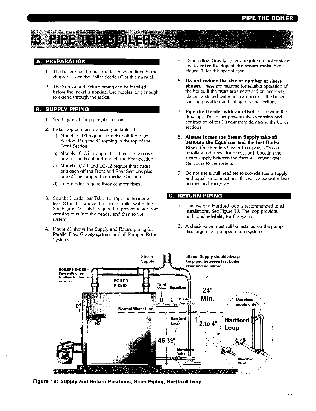
Size the Header per Table 11. Pipe the header at
least 24 inches above the normal boiler water line.
See Figure 19. This is required to prevent water from
carrying over into the header and then to the
system.
Figure 21 shows the Supply and Return piping for
Parallel Flow Gravity systems and all Pumped Return
Systems.
I. The use of a Hartford loop is recommended in all
installations. See Figure 19. The loop provides
additional reliability for the system.
2. A check valve must still be installed on the pump
discharge of all pumped return systems.
BOILER HEADER -
Pipe with offset
to allow for header
expansion
Steam
Supply
Steam Supply should always
be piped between last boiler
riser and equalizer.
I
24"
Min. ." Use close
x i
To 4" "Hartford
,Loop
Figure 19: Supply and Return Positions, Skim Piping, Hartford Loop
Blowdown /"
Valve .
/+
I
!
21
3.
Boiler Riser Piping
enters TOP of main
on Counterflow
System _ 4
Counterflow
Steam Main 6.
I)]q I fldaJallll:J ii=l I:{e] lit :I:llL_LL't IL,11iW_'_lll[O]t__
2" Skim
Connection
Figure 20: Supply and Return Piping -
Counterflow Gravity Systems
Pitch T
ualizer
On pumped return systems, install a boiler cock after
the pump to allow throttling of the pump discharge.
The pressure after the boiler cock should be no more
than 5 psig above the boiler operating pressure.
Pumping the water into the boiler too fast will cause
collapse of the water level and level control problems.
Size the equalizer per Table 11. Models LC II, LC-
12 and LCE-13 through LCE 24 require two return
connections to the boiler off of the equalizer line.
Pipe the Hartford loop tee so the inside top of the
close nipple is 2 to 4 inches below the normal boiler
water line. See Figure 19.
If the pump discharge is looped overhead, above the
boiler water line, install spring loaded check valves at
both the pump discharge and the connection to the
boiler return.
1.
2.
3.
4.
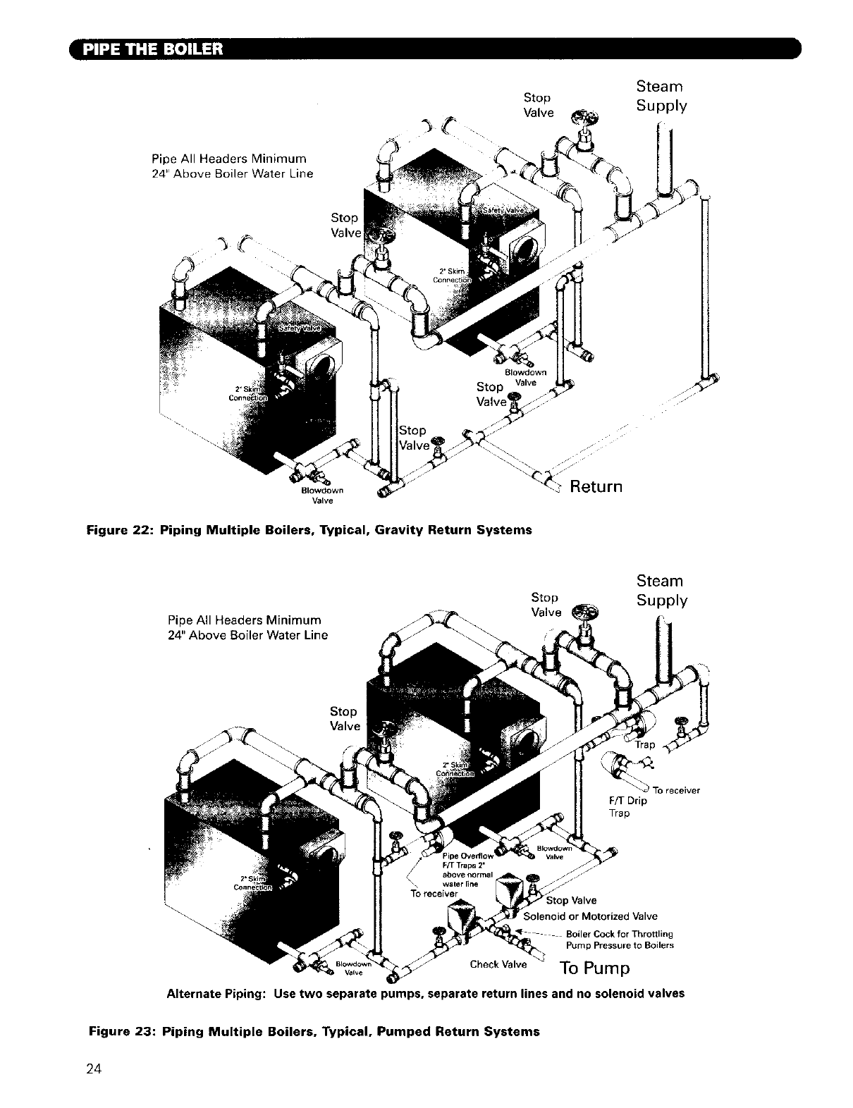
Figure 22 shows typical piping for multiple boiler
Gravity Return systems. Figure 23 show typical
piping for multiple boiler Pumped Return Systems•
Provide separate feed lines for multiple boiler
pumped return systems. Use either separate feed
pumps or solenoid or motorized valves to isolate
feeding of the boilers. This is needed to provide
reliable level control and avoid nuisance
performance problems.
Condensate return units are not effective for multiple
boiler installations since they do not respond to the
needs of the boilers• always use Boiler Feed Units.
Install a Float and Thermostatic trap at the boiler
water level on each of the mufltple boilers on a
pumped return system• This prevents flooding of idle
boilers due to condensation of steam•
Table 11: Header, Risers r: Equalizer Sizing
I=B=R End Section Intermediate Section
Model Gross !! Risers Risers Equalizer HeaderSize
Output Size Size (inches)
Number (Inches)
MBH Number (Inches) (Inches)
7
LC-04 547
LC-05R 649
LC-05 707
LC-O6 868
LC-O7 1029
LC-08 1189
LC-09 1350
LC-10 1511
LC-11 1672 ;
LC-12 1832 !
LCE-13
LCE-14
LCE-15
LCE-16
LCE-17
LCE-18
LCE-19
LCE-20
LCE 21
LCE-22
LCE-23
LCE-24
1966
2125
2284
2444
2603
2763
2922
3082
3256
3430
3604
3777
1 4
23
2 3
2 4
2 4
2 4
2 4
2 4
2 4
2 4
2 4
2 4
2 4
2 4
24
2 4
2 4
2 4
2 4
2 4
2 4
2 4
2
2
2
2
21/2
2½
21/2
1 3 3
1 3 3
1 3 3
233
2_33
233
334
334
334
434
434
434
43 4
434
4
5
5
5
5
6
6
6
6
6
6
8
8
8
8
8
8
8
8
8
8
8
22
I ;1I_ _ _ -i-i-i-i-i-i-i-i-i__ _I
LCE-13 THRU LCE-24
TWO END RISERS
ONE OR MORE INTERMEDIATE RISERS
TWO RETURN CONNECTIONS
Figure 21: Supply and Return Piping - Pumped Return and Parallel Flow Gravity Systems
23
l_1_llill_ I;I.]TI-_;t
Steam
Stop Supply
Valve
Pipe All Headers Minimum
24" Above Boiler Water Line
Stop
Valve
Blowdown
Valve
Figure 22: Piping Multiple Boilers, Typical, Gravity Return Systems
Pipe All Headers Minimum
24" Above Boiler Water Line
Stop
Valve
Steam
Supply
Stop
Valve
_f_\_ receiver
F/I- Drip
Trap
) Valve
_'_. ;olenoid or Motorized Valve
Boiler Cock for Throttling
Pump Pressure to Boilers
Check Valve To Pump
Valve
Alternate Piping: Use two separate pumps, separate return lines and no solenoid valves
Figure 23: Piping Multiple Boilers, Typical, Pumped Return Systems
24
"_1 "J,| :1_:_ H _ //'l:I _:! ;| |
le]i Ir:q"] "]k'd IqiL'Te.][4:il/ IH:I_,I:g :I_,1L_1:1
2.
Collect all the jacket cartons: Jacket Front & Back
Carton plus Jacket Side & Top Cartons. See
the Shipping List in the front of this manual for the
jacket cartons required. The cartons contain the
jacket parts and screws• The jacket panels are pre-
insulated.
Remove all needed knockouts from the jacket parts
before beginning assembly,
2.
3.
1.
Attach the Middle Front Panel and Lower Front Rail
in the same manner.
Position the Jacket Assembly with the front panels
pushed up against the front section. You will need
the jacket in this position to install the Burner Front
Plate•
Attach the Rear Jacket Panel to the Jacket Side
Panels with #10 x 1/2" sheet metal screws.
I:R F-'N']'.Jk'd qY_'To.][4:ill _"lle] :(,:]r,_lL_le][e.[e];]_l:4:[,: I_q V*-N']:,lk'd [qY:Te'][4:il/ll[e]:.i__,NLH:tl_
1.
2.
3.
4.
5.
6.
7. I=1 r_W_l_Jk"4I'.,,IW'.._Ii::(-_F;1L'_IO]lir_,l:]::ll_
[o46r_,'q-.,l:JiVdPlr±Te.][4::illiH:l:{e]b,'1|l i_._I_1:ii(_
1.
Table 12:
Model
LCE-13
LCE-14
LCE-15
LCE-16
LCE-17
LCE-18
LCE-19
LCE-20
LCE-21
LCE-22
LCE-23
LCE-24
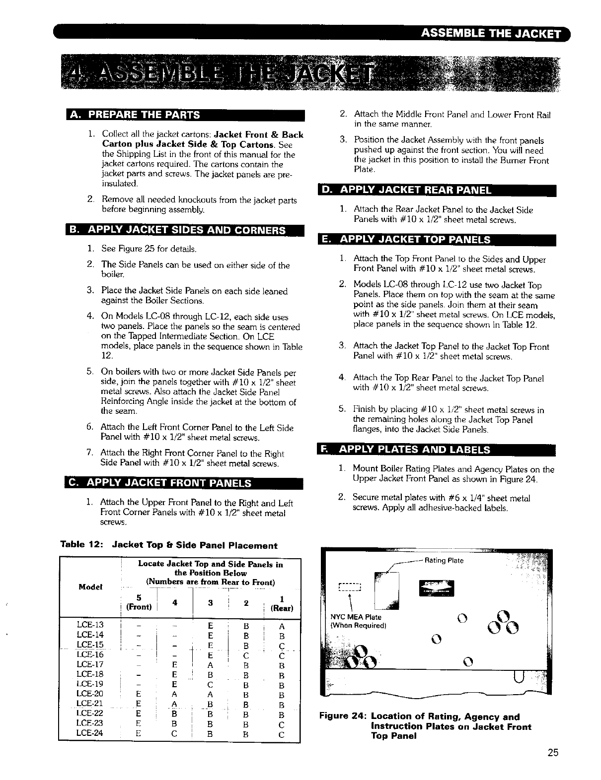
See Figure 25 for details.
The Side Panels can be used on either side of the
boiler.
Place the Jacket Side Panels on each side leaned
against the Boiler Sections.
On Models LC-08 through LC-12, each side uses
two panels. Place the panels so the seam is centered
on the Tapped Intermediate Section. On LCE
models, place panels in the sequence shown in Table
12.
On boilers with two or more Jacket Side Panels per
side, join the panels together with #I0 x I/2" sheet
metal screws. Also attach the Jacket Side Panel
Reinforcing Angle inside the jacket at the bottom of
the seam.
Attach the Left Front Corner Panel to the Left Side
Panel with # i0 x 1/2" sheet metal screws.
Attach the Right Front Corner Panel to the Right
Side Panel with #10 x i/2" sheet metal screws.
Attach the Upper Front Panel to the Right and Left
Front Corner Panels with #i0 x 1/2" sheet metal
SCreWS.
Jacket Top bSide Panel Placement
5 T
(Front) I4I
-E
I E
E A
E B
T
1 E C
E A A
E A B
E B B
E B B
E C [ B
Locate Jacket Top and Side Panels in
the Position Below
(Numbers are from Rear to Front)
21
i (Rear)
B A
B
C
€
B
B
B
B
B B
B B
C
C
i.
2.
3.
4.
5.
Attach the Top Front Panel to the Sides and Upper
Front Panel with #I0 x 1/2" sheet metal screws.
Models LC-08 through LC-12 use two Jacket Top
Panels. Place them on top with the seam at the same
point as the side panels• Join them at their seam
with #10 x 1/2" sheet metal screws. On LCE models,
place panels in the sequence shown in Table 12.
Attach the Jacket Top Panel to the Jacket Top Front
Panel with #I0 x 1/2" sheet metal screws•
Attach the Top Rear Panel to the Jacket Top Panel
with #I0 x 1/2" sheet metal screws.
Finish by placing #10 x i,,'2" sheet metal screws in
the remaining holes along the Jacket Top Panel
flanges, into the Jacket Side Panels.
i.
2.
Mount Boiler Rating Plates and Agency Plates on the
Upper Jacket Front Panel as shown in Figure 24.
Secure metal plates with #6 x 1/4" sheet metal
screws. Apply all adhesive-backed labels.
0
0
Figure 24: Location of Rating, Agency and
Instruction Plates on Jacket Front
Top Panel
25
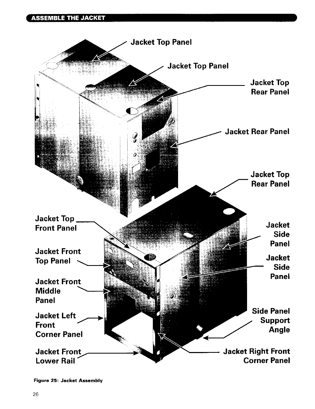
•I
Jacket Top
Front Panel
Jacket Front
Top Panel
Jacket Front
Middle
Panel
Jacket Left
Front
Corner Panel
Jacket Front
Lower Rail /
Jacket Top Panel
Jacket Top Panel
I
I
Jacket Top
Rear Panel
Jacket Rear Panel
Jacket Top
Rear Panel
Jacket
Side
Panel
Jacket
Side
Panel
Side Panel
Support
Angle
Jacket Right Front
Corner Panel
Figure 25: Jacket Assembly
26
Refer to Chapter I, preinstallation, Section D. Chimney,
or Vent for installation requirements. Refer to
Chapter 9. Startina the Boiler, Section C. Run Burner
Check Out for damper settings and draft requirements.
r:! I:{II:|L_I:I;t r:1:J'Jl[l'Y:_li[e]{
1. Refer to Burner Spec and Data Sheets for the Oil
and Gas/Oil Burners pre-tested with Series LC
boilers.
2. Make sure the nozzle sizing and spray pattern match
those given in the spec and data sheets.
[I,_ hVA[ellJL_ll I1:1: I:|II:|LII=I_
3. See Figure 26 and Table 13 for combustion chamber
dimensions.
I:_ IIL_-"]llr±!llli:]lJ-'_,_l=l;! I_v_[_l|JL_illlh_[ClI;.lff-_lll
I. The Burner Mounting Plate is made to fit the burner
being used. Burners vary in bolt pattern for the
flange, burner tube diameter, insertion length and
near-tube configuration. Make sure the front plate is
correct for your burner if purchased separately from
the boiler.
2. Remove the Burner Mounting Plate and Hardware
Bag from the crate.
3_
4.
1.
2.
3.
4.
Screw (7) 3/8"-16 x 21/4"studs into the holes in the
front section around the chamber opening.
Secure the Burner Mounting Plate to the front
section with the fiat washers and hex nuts.
Remove the Burner from its crate. Read the burner
instructions.
Insert (4) 3/8"-16 x II/4'' studs supplied with Burner
Mounting Plate into the front plate holes.
Place the high temperature gasket on the burner
front plate and secure the burner to the front plate
with 3/8" fiat washers and hex nuts.
If the burner is supplied with a pedestal, install it to
the burner per the Burner Manufacturer's
Instructions. The pedestal provides additional
support and prevents the burner from sagging.
27
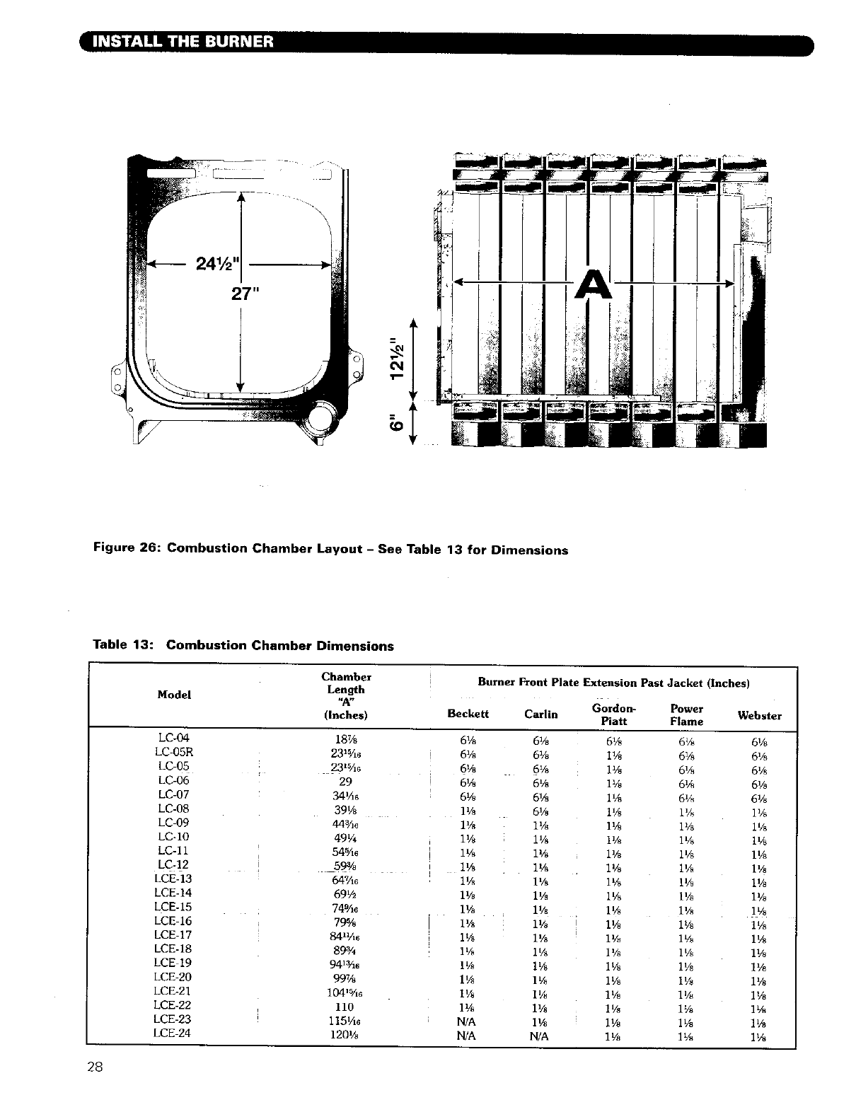
:I
Figure 26: Combustion Chamber Layout - See Table 13 for Dimensions
Table 13: Combustion Chamber Dimensions
Chamber Burner Front Plate Extension Past Jacket (Inches)
Model Length
"A" Gordon- Power
(Inches) Beckett Carlin Piatt Flame Webster
LC-04
LC-05R
LC-05
LC-06
LC-07
LC-08
LC-09
LC-IO
LC-11
LC-12
LCE-13
LCE-14
LCE-15
LCE-16
LCE-17
LCE-18
LCE 19
LCE-20
LCE-21
LCE-22
LCE-23
LCE-24
18%
23W16
23_5Ao
29
34¼€
39V_
44¾,3
49V4
54_A6
59%
647A0
69V2
749A€
79%
84_¼6
89%
941¾_
99%
104'5A6
110
1151/16
1201/8
6%
6%
6%
6V8
6_
11/8
1%
IYs
11/8
11/_
11/8
1%
11/8
1%
1%
11/_
1%
1%
1%
N/A
N/A
61/s
6%
6%
6%
6Vs
61/8
i%
II/8
1%
1%
IVs
II/8
11/_ i
i
1%
1%
I%
1Vs
U/s
1%
I%
NIA
6gs
I%
ll/s
1%
I%
11/8
1%
IV8
11/8
1%
1%
I%
II/8
IV8
11/8
I%
1%
I%
1%
11/8
I%
i'/8
6% 6%
6% 6%
6% 6%
6Va 6Vs
6_×_ 6V8
1% I%
I_/8 I%
I% I%
I% IV8
IVa IV8
IV_ IV8
1Vs 1Vo
1V8 1%
1% IVs
1% 1%
1% IV_
I% 1%
IV8 1%
IV_ 1%
i% 1%
IV8 1Ve
1% 11/_
28
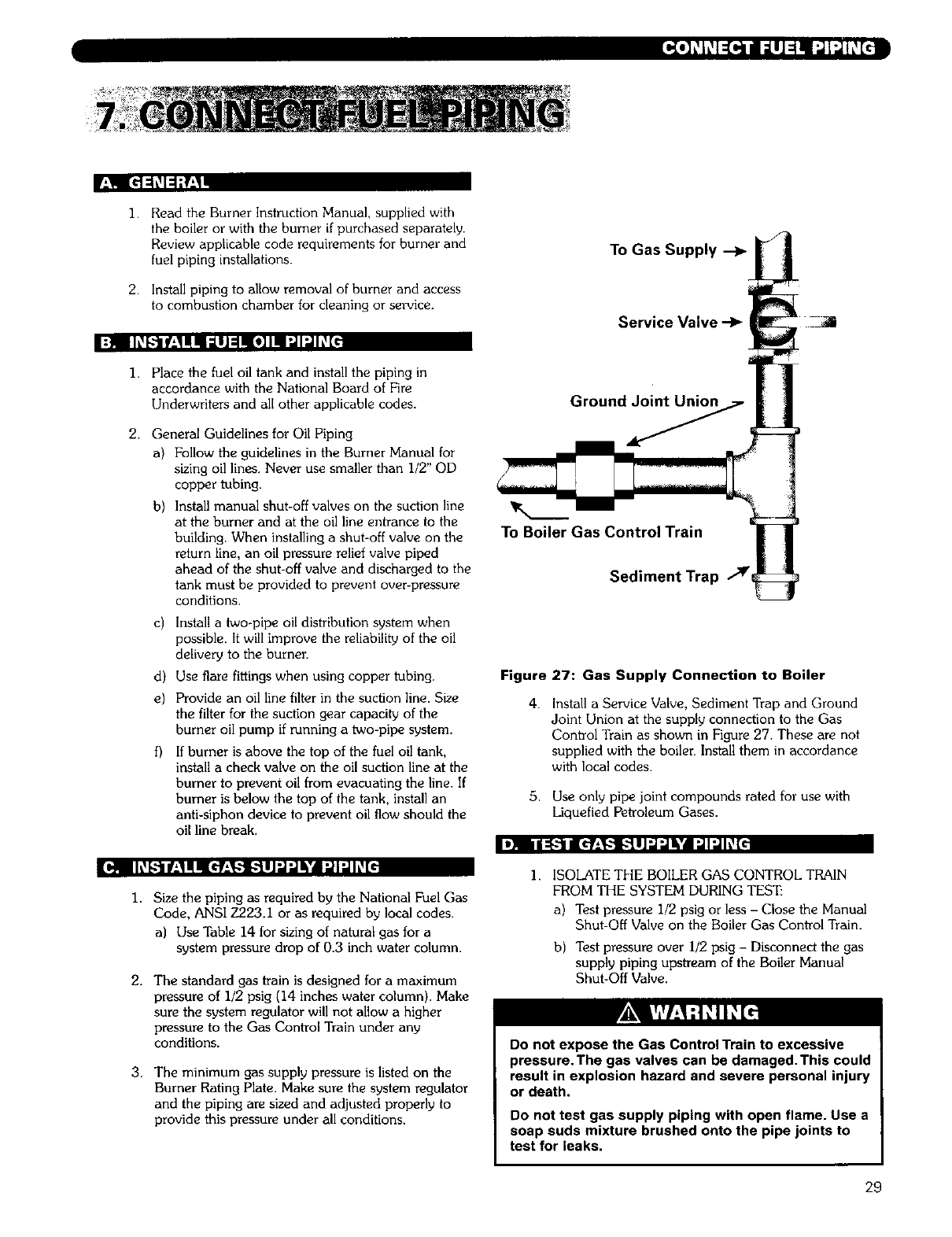
[_o]_ h'_1:(..inuI _LIJ=lml["_1"J_c7
I
].
2.
Read the Burner Instruction Manual, supplied with
the boiler or with the burner if purchased separately.
Review applicable code requirements for burner and
fuel piping installations.
Install piping to allow removal of burner and access
to combustion chamber for cleaning or service.
To Gas Supply --_
Service Valve -1_ -_
I=J IIL_l_"]llr'-l!ll:llJ =lll0]ll ",JI_IL_[,
1.
2.
Place the fuel oil tank and install the piping in
accordance with the National Board of Fire
Underwriters and all other applicable codes.
General Guidelines for Oil Piping
a) Follow the guidelines in the Burner Manual for
sizing oil lines. Never use smaller than I/2" OD
copper tubing.
b)
c)
d)
e)
Install manual shut-off valves on the suction line
at the burner and at the oil line entrance to the
building. When installing a shut-off valve on the
return line, an oil pressure relief valve piped
ahead of the shut-off valve and discharged to the
tank must be provided to prevent over-pressure
conditions.
Install a two-pipe oil distribution system when
possible. It will improve the reliability of the oil
delivery to the burner.
Use flare fittings when using copper tubing.
Provide an oil line filter in the suction line. Size
the filter for the suction gear capacity of the
burner oil pump if running a two-pipe system.
If burner is above the top of the fuel oil tank,
install a check valve on the oil suction line at the
burner to prevent oil from evacuating the line. If
burner is below the top of the tank, install an
anti-siphon device to prevent oil flow should the
oil line break.
Ground_
To Boiler Gas Control Train
Sediment Trap
Figure 27: Gas Supply Connection to Boiler
4. Install a Service Valve, Sediment Trap and Ground
Joint Union at the supply connection to the Gas
Control Train as shown in Figure 27. These are not
supplied with the boiler. Install them in accordance
with local codes.
5. Use only pipe joint compounds rated for use with
Liquefied Petroleum Gases.
t! II_-I Icf:!-I [--"].ll"J_k'dN _l:,,,lh,'_[_
ion Ih.'_[.-"lllr'_llIIc'f_'l,-"] [.'.llJ'J'Jli'd ".,]I'ilh,'1[€
1,
2.
3.
Size the piping as required by the National Fuel Gas
Code, ANSI Z223.1 or as required by local codes.
a) Use Table 14 for sizing of natural gas for a
system pressure drop of 0.3 inch water column.
The standard gas train is designed for a maximum
pressure of 1/2 psig (14 inches water column). Make
sure the system regulator will not allow a higher
pressure to the Gas Control Train under any
conditions.
The minimum gas supply pressure is listed on the
Burner Rating Plate. Make sure the system regulator
and the piping are sized and adjusted properly to
provide this pressure under all conditions.
I. ISOLATE THE BOILER GAS CONTROL TRAIN
FROM THE SYSTEM DURING TES_
a) Test pressure 1/2 psig or less - Close the Manual
Shut-Off Valve on the Boiler Gas Control Train.
b) Test pressure over 1/2 psig -Disconnect the gas
supply piping upstream of the Boiler Manual
Shut-Off Valve.
Do not expose the Gas Control Train to excessive
pressure.The gas valves can be damaged.This could
result in explosion hazard and severe personal injury
or death.
Do not test gas supply piping with open flame. Use a
soap suds mixture brushed onto the pipe joints to
test for leaks.
29
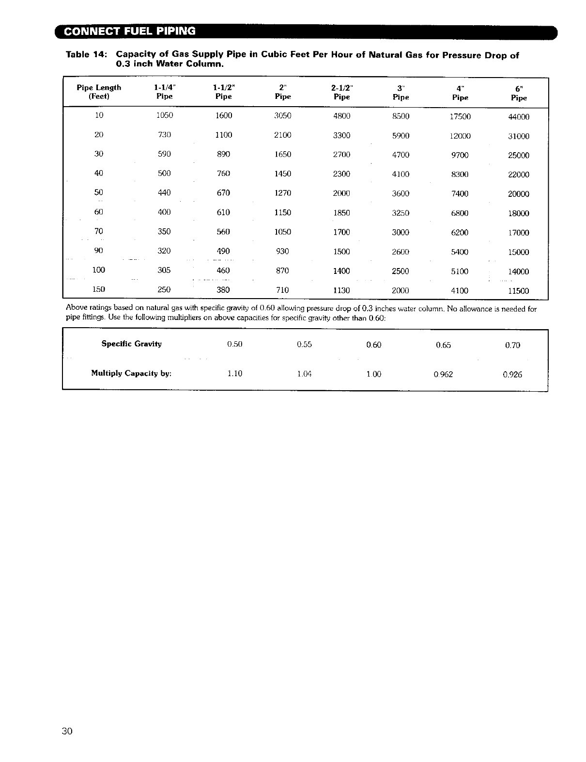
Table 14: Capacity of Gas Supply Pipe in Cubic Feet Per Hour of Natural Gas for Pressure Drop of
0.3 inch Water Column,
Pipe Length 1-1/4" 1-1/2" 2" 2-1/2" 3" 4"
(Feet) Pipe Pipe Pipe Pipe Pipe Pipe
10 1050 1600 3050 4800 8500 17500
20 730 1100 2100 3300 5900 12000
30 590 890 1650 2700 4700 9700
40 500 760 1450 2300 4100 8300
50 440 670 1270 2000 3600 7400
60 400 610 1150 1850 3250 6800
70 350 560 1050 1700 3000 6200
90 320 490 930 1500 2600 5400
I00 305 460 870 1400 2500 5100
150 250 380 710 1130 2000 4100
6 t,
Pipe
44OO0
31000
25000
22000
20000
18OOO
17OOO
15OOO
14OO0
11500
Above ratings based on natural gas with specific gravity of 0.60 allowing pressure drop of 0.3 inches water column. No allowance is needed for
pipe fittings. Use the following multipliers on above capacities for specific gravity other than 060:
Specific Gravity 0.50 0.55 060 0.65 0.70
Multiply Capacity by: 1.10 104 1 O0 0962 0.926
3O
r,l Ih_[..'_lf;11lll_',]r;1;;l::illk'4LVl;1IkvJ=[.. ID31IIs_[_"]llr;!llt!I;,l:?:k."_'_lJ:|::l[I,[i]_//:(t]l_
i. Pipe the Pop Safety Valve on a tee mounted in the
2]/2'' tapping located on the upper ]eft side of the
Rear Section. Make sure the relief valve sizing meets
local code requirements.
3. Pipe the Steam Pressure Gauge and Boiler Limit and
Operating Pressure Controls as shown in Figure 30.
Connect the control assembly to the I/2" tapping in
the front section.
Pipe the discharge of the Safety Relief Valve away
from any traffic area, preferably to a floor drain. This
is necessary to prevent injury should the valve
discharge.
Pipe the discharge full size of valve outlet.
Make sure that the ignition system components,
electrical controls, junction boxes and electrical
panels are protected from water (dripping, spraying,
rain, etc.) during boiler operation and service (trap
servicing, control replacements or other).
2. Install a 2" ball valve for skimming off the end of the
tee as shown in the piping drawings in this manual.
I;]tl Ih,_[,,:"JrIt_'111 1:] Ko]I,_I| tp[olr,_|_,'_I kVl'_1IkvJ=[-;
1. Install a IL/Z"full port ball valve off of the return
connection as shown in the "Pipe the Boiler" section
of this manual. See Figure 28.
I:q [Ke]L_h_l:[_l/[,."J.uJ:,l:,llk'dLrAVJlHh_[€
2. Pipe the valve discharge to a floor drain if available
or apply a nipple and cap to close off when not in
USe.
1:11 -,JI "]:11it_,1t_I [41 =k'_l: I:f_,t /: :ll_
1. Connect piping to any installed tankless heaters. See
Figure 35 for suggested piping for single coils and
Figure 36 for suggested piping for dual coils.
1. Install all wiring in accordance with local codes, the
National Electrical Code and other controlling
agencies or governing bodies.
tel! Ih,'ql,,,_Ir_'lll! lU(ol_l_ir_,rr_'_lti=l-"l_l,,]ljl[O]-I:r,{___
1. Mount a float type Low Water Cutoff and Gauge
Glass in the tappings provided in the side of the front
section or the side and top of the first intermediate
section.
2. Do not apply piping which would raise or lower the
location of the cutoff relative to the tappings in the
boiler. Raising the water level over the design height
will cause water carryover to the system.
3. For correct location of typical low water cutoff/feeder
or low water cutoff/pump control, see Figures 31
through 34.
4. See Figure 29 for the location of control connection
tappings.
5. Provide each float low water cutoff with a blowdown
valve. Pipe the blowdown away from traffic to a floor
drain if available. The blowdown valve is required
for proper maintenance of the control.
6. Maintain a height of 461/2" from boiler foundation to
the normal water level.
7. When using Multiple Float Type Controls: Always
pipe the controls off of the same tappings to the
boiler. Do not mount on different ends of the boiler
or in different tappings. This can cause erratic
operation and nuisance problems with the controls.
The boiler/burner must be electrically grounded in
accordance with the requirements of the authority
having jurisdiction, or in the absence of such
requirements, with the current edition of the National
Electrical Code, ANSI/NFPA Number 70.
2.
3.
4.
Use #14 gauge or heavier wire for supply wiring.
Protect the circuit with a fused disconnect switch (by
others) and a grounded neutral.
Mount an electrical junction box on the boiler Front
Panel for connection of supply wiring and
distribution to the boiler controls.
Follow the instructions in the Burner Manual and the
Wiring Diagrams supplied with the burner and the
boiler.
31
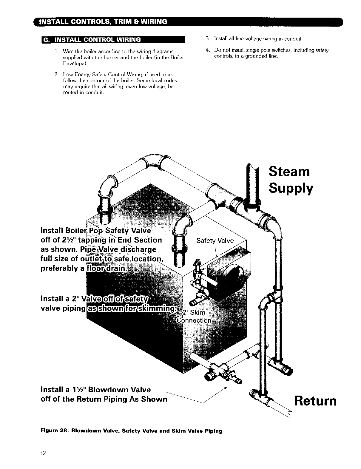
¢H h_l.."l Ih_1I! IKa,(o] _ilII;{o] INr_,_iI; i h_[_.
I. Wire the boiler according to the wiring diagrams
supplied with the burner and the boiler (in the Boiler
Envelope)
2. Low Energy Safety Control Wiring, if used, must
follow the contour of the boiler. Some local codes
may require that all wiring, even low voltage, be
routed in conduit.
3 Install all line voltage wiring in conduit
4. Do not install single pole switches, including safely
controls, in a grounded line.
Steam
Supply
Install Boiler
off of 21/2"tapp,ng in_End Section
as shown. Pi
full size
preferably a
Install a 2"
valve piping
Install a 11/2'' Blowdown Valve n_
off of the Return Piping As Show Return
Figure 28: Blowdown Valve, Safety Valve and Skim Valve Piping
32
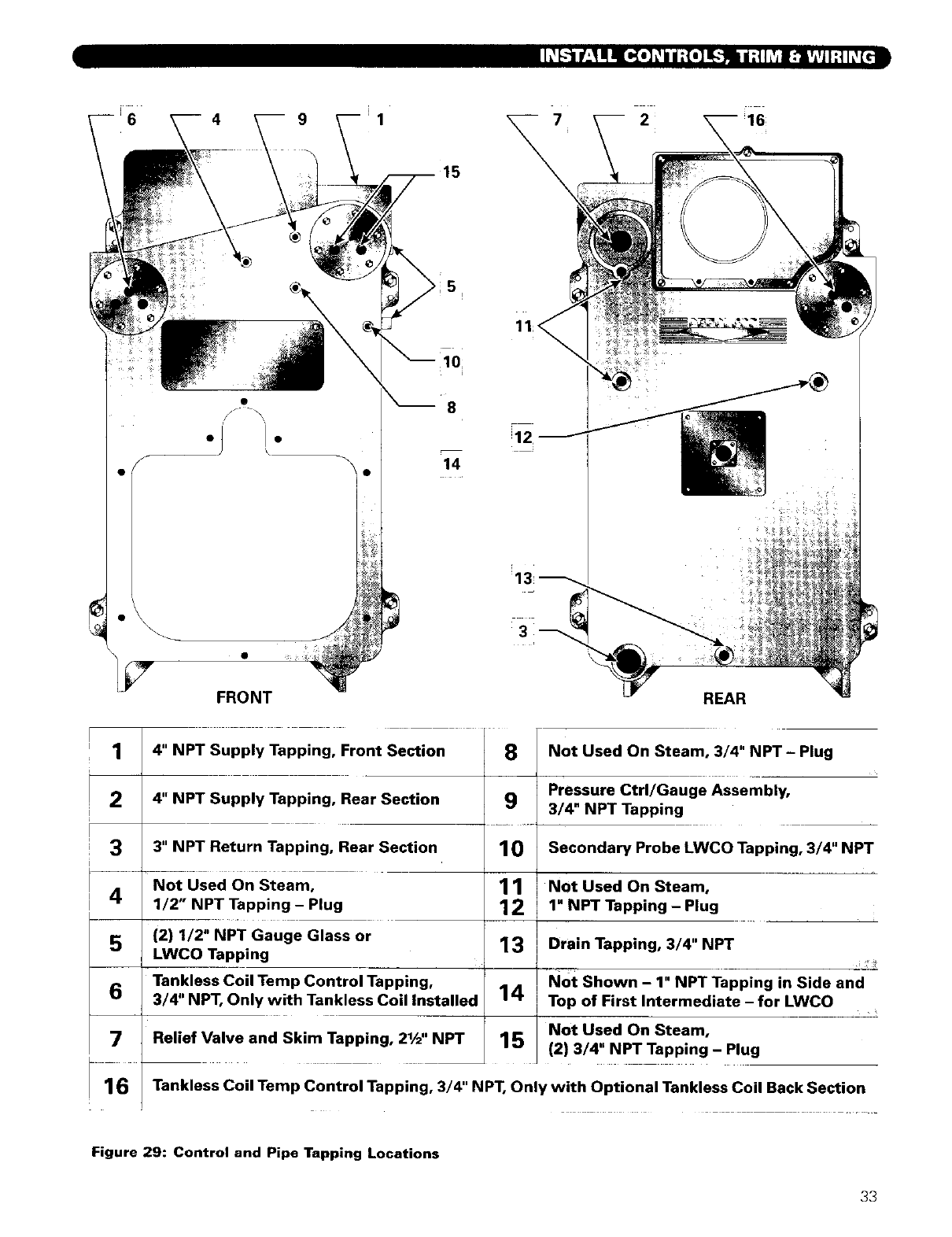
i
6 4 9 1 2 16;
f
e
7FRONT
15
10
8
14
11;<
REAR
1
2
3
4
5
6
7
16
4" NPT Supply Tapping, Front Section 8
4" NPT Supply Tapping, Rear Section 9
3" NPT Return Tapping, Rear Section 10
Not Used On Steam, 11
1/2" NPT Tapping - Plug 12
(2) 1/2" NPT Gauge Glass or 13
LWCO Tapping
Tankless Coil Temp Control Tapping,
3/4" NPT, Only with Tankless Coil Installed 14
Relief Valve and Skim Tapping, 21/2"NPT 15
Not Used On Steam, 3/4" NPT - Plug
Pressure Ctrl/Gauge Assembly,
3/4" NPT Tapping
Secondary Probe LWCO Tapping, 3/4" NPT
Not Used On Steam,
1" NPT Tapping - Plug
Drain Tapping, 3/4" NPT
NOt Shown - 1" NPT Tapping in Side and
Top of First Intermediate - for LWCO
Not Used On Steam,
(2) 3/4" NPT Tapping - Plug
Tankless Coil Temp Control Tapping, 3/4" NPT, Only with Optional Tankless Coil Back Section
Figure 29: Control and Pipe Tapping Locations
33
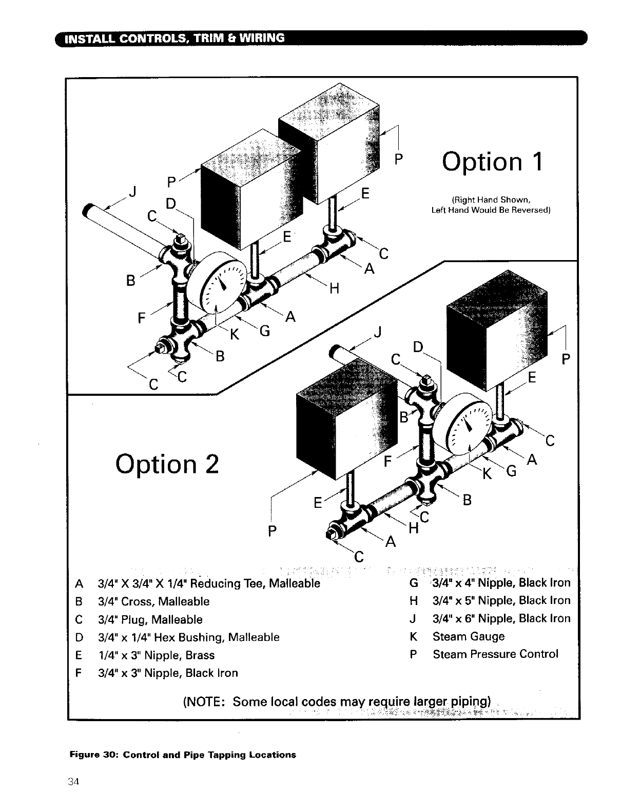
.]_[--_t'_] _ ['_k'i]_ -o_I_]_], _J;th'_l [:1_JIfll_[_
J
E
POption 1
(Right Hand Shown,
Left Hand WouEd Be Reversed)
F
CI
E
P
Option 2
PC
A
A
B
C
D
E
F
3/4" X 3/4" X 1/4" Reducing Tee, Malleable
3/4" Cross, Malleable
3/4" Plug, Malleable
3/4" x 1/4" Hex Bushing, Malleable
1/4" x 3" Nipple, Brass
3/4" x 3" Nipple, Black Iron
G 3/4" x4" Nipple, Black Iron
H 3/4" x 5" Nipple, Black Iron
J 3/4" x 6" Nipple, Black Iron
K Steam Gauge
PSteam Pressure Control
(NOTE: Some local codes may require larger piping)
Figure 30: Control and Pipe Tapping Locations
34
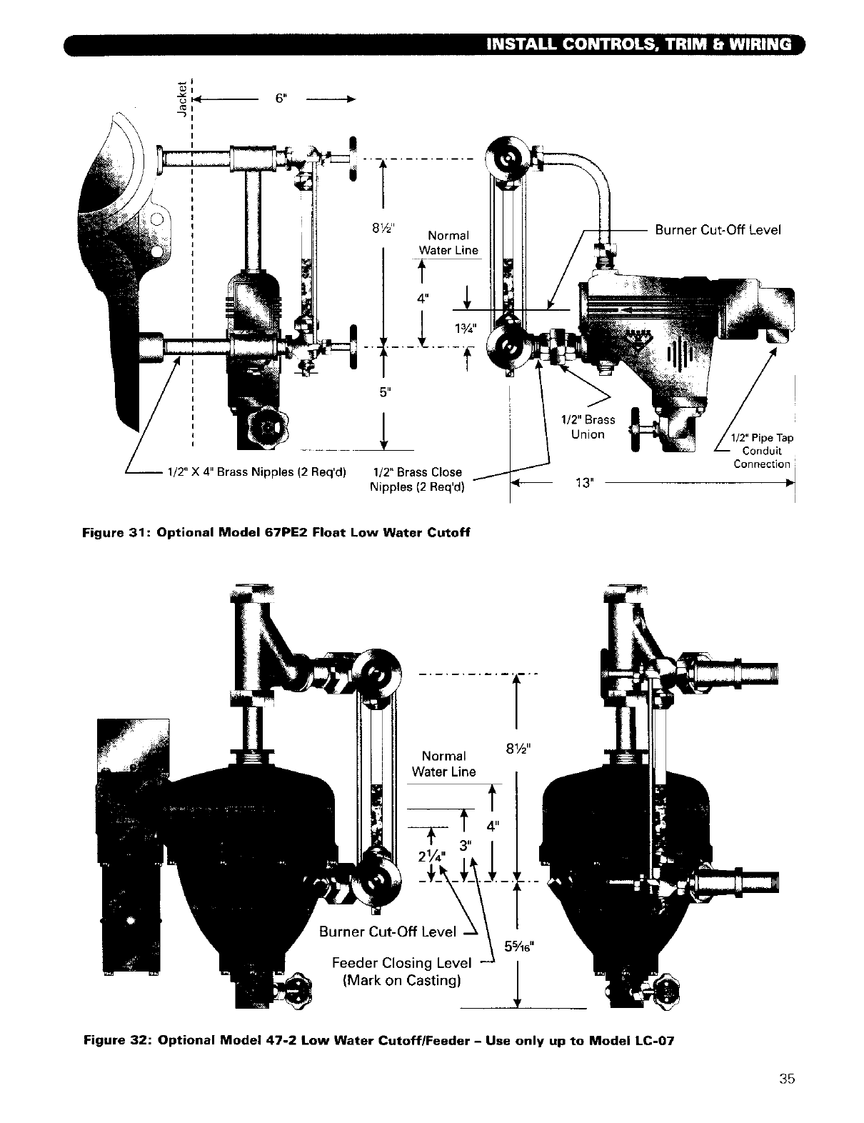
!
1/2" X 4" Brass Nipples (2 Req'd) 1/2" Brass Close
Nipples (2 Req'd)
/>
1/2" Brass
Union
-- Burner Cut-Off Level
/-- Conduit
Connection
Figure 31: Optional Model 67PE2 Float Low Water Cutoff
Normal
Water Line
Burner Cut-Off Level
Feeder Closing Level
(Mark on Casting)
81/2 ''
t
Figure 32: Optional Model 47-2 Low Water Cutoff/Feeder - Use only up to Model LC-O7
35
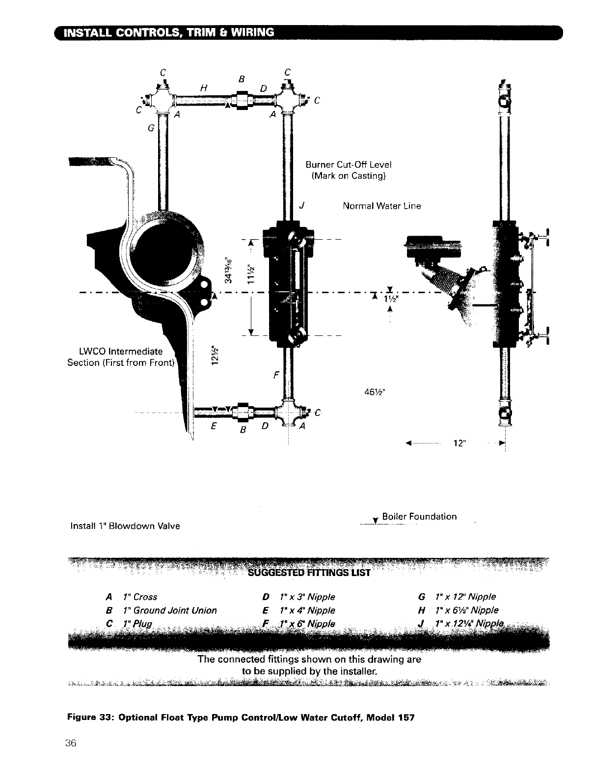
74;,] Ii;1177f4lTffitI 4
G
LWCO Intermediate
Section (First from
C
A
H
=_
E
B
B
C
A
F
Burner Cut-Off Level
Casting)
JNormal Water Line
12"
Install 1" Blowdown Valve Boiler Foundation
A 1" Cross DI" x 3" Nipple G1" x 12" Nipple
B 1" Ground Joint Union E I" x 4" Nipple N1" x 61/d'Nipple
C J
The connected fittings shown on this drawing are
to be supplied by the installer.
Figure 33: Optional Float Type Pump Control/Low Water Cutoff, Model 157
36
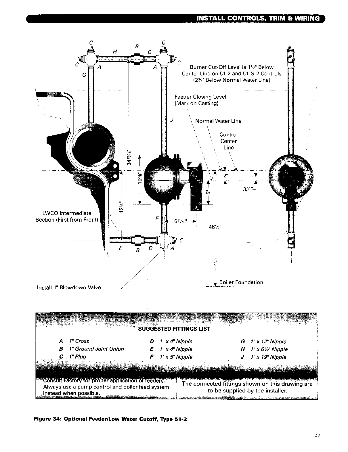
'. V *
1
B
A
C
Burner Cut-Off Level is 1V2"Below
Center Line on 51-2 and 51-S-2 Controls
(23/4" Below Normal Water Line)
Feeder Closing Level
(Mark on Castingj
JNormal Water Line
Control
Center
Line
LWCO Intermediate
Section (
E B f
/
Install 1" Blowdown Valve y_Bo!le[ Foundation
SUGGESTED FITTINGS LIST
A1" Cross D1" x 4" Nipple G1" x 12" Nipple
B1"GroundJointUnion El"x4"Nipple H1"x61/2"Nipple
C 1" Plug FI" x _' Nipple d1" x 19" Nipple
Always use a pump control and boiler feed system The connected fittings shown on this drawing are
to be supplied by the installer.
Figure 34: Optional Feeder/Low Water Cutoff, Type 51-2
37
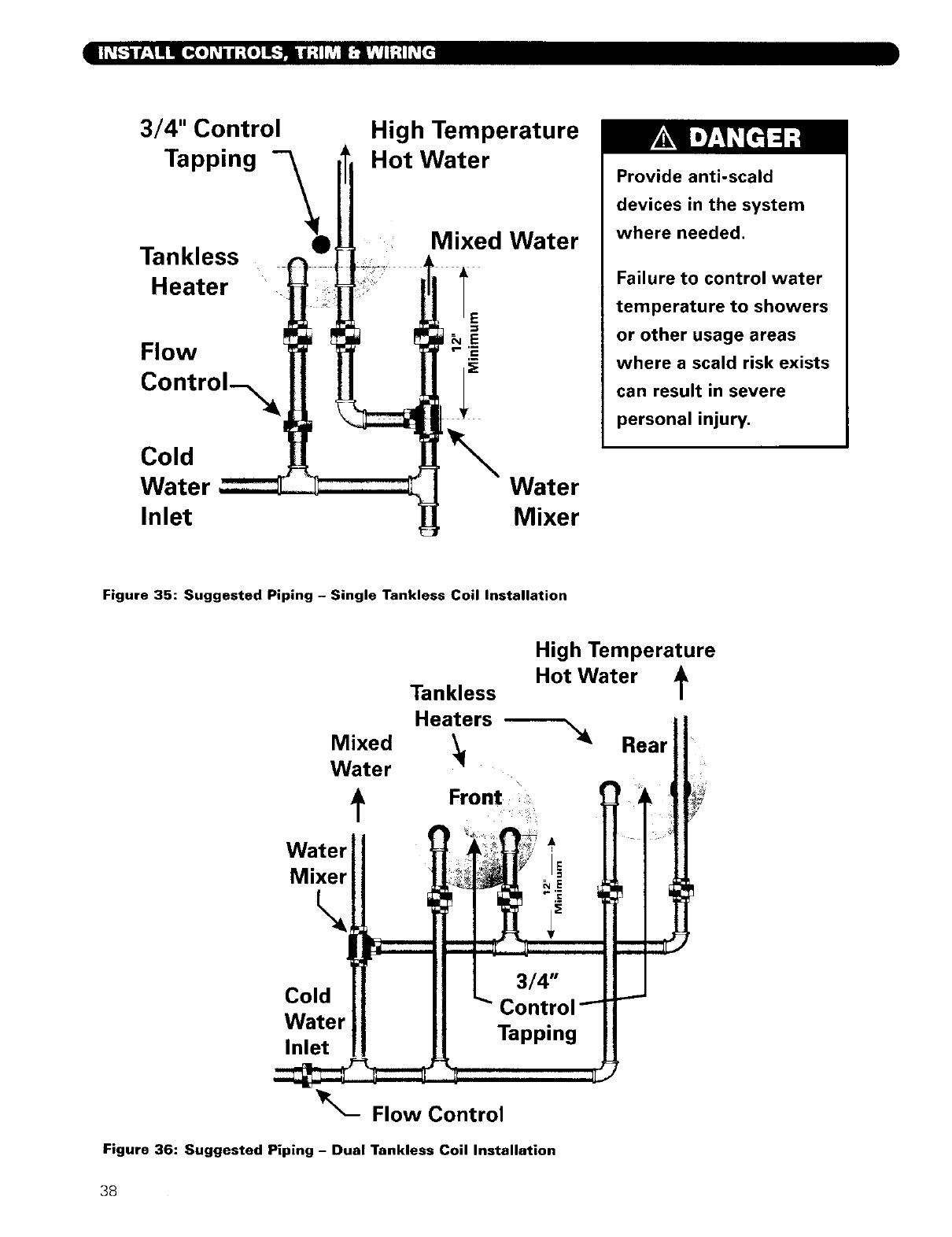
3/4" Control
Tapping
Tankless
Heater
Flow
Cold
Water
Inlet
High Temperature
Hot Water
Mixed Water
NE
Water
Mixer
Provide anti-scald
devices in the system
where needed.
Failure to control water
temperature to showers
or other usage areas
where a scald risk exists
can result in severe
personal injury,
Figure 35: Suggested Piping - Single Tankless Coil Installation
Water
Mixer
High Temperature
Tankless Hot Water
Heaiers
Mixed _4_ Rear "
Water
Front ,
V
Is
Cold
Watel
Inlet Tapping
Flow Control
Figure 36: Suggested Piping - Dual Tankless Coil Installation
38
"-!1 [_:l_[li:l; I']l'J h_[4
I. Steam Piping
a) The Boiler must have been hydrostatically tested.
b) Check the attached piping for joint tightness.
c) Continue monitoring as you proceed through
start up.
2. Gas Piping
a) Make sure the gas system piping and the
connections to the Boiler Gas Control Train(s)
have been leak tested.
b) After the boiler is in operation, check the
tightness of all joints in the boiler gas piping with
a soap suds solution.
c) Purge the gas piping of all air up to the boiler
Gas Control Train.
3. Oil Piping
a) Check the oil piping visually. Make sure all joints
are tight.
b) When the burner is firing, check the suction line
and return line pressures.
c) If the pressure exceeds the allowable pressure in
the Burner Manual or if the suction line vacuum
is higher than allowable, correct the piping as
needed to bring the suction line and return line
pressures within acceptable range.
I_ [_'I:[*,]H I:{o]ll_:l(t]L_ll;lo]_
d) Excess pressure can cause pump seal failures.
Excess vacuum will cause fuel flow problems
with the burner oil pump.
:tl I=11 II i :l:l I:{*]lllq;
i. Fill the boiler to the normal water line.
a) Gravity Systems and Pumped Return with
Condensate Units - Fill to 461/2" above the boiler
foundation (center of gauge glass).
b) Pumped Return with Boiler Feed Unit -Fill the
boiler using the boiler feed unit. Fill level will
depend on the control being used, but should be
461/2" above the boiler foundation (just below
center of gauge glass) when the pump stops.
4.
5.
When a barometric draft regulator is installed in the
venting system, adjust the boiler damper for 0" wc
pressure reading at the damper. Adjust the draft
regulator for -005" wc draft between the boiler
damper and the draft regulator.
Adjust the burner as needed for a CO 2 reading of:
a) Oil burners: CO 2 approximately 12.5% or I%
less than the level at which the smoke reading
goes above a trace on the Bacharach scale.
b) Gas burners: 9% to 10% with CO less than 50 ppm.
Inspect al[ flue gas joints (sections, attachments,
breeching and vent) for gas tightness. Remove the
jacket panels in order to thoroughly inspect all rope
seal joints between the sections.
On installations with high draft, do not leave the
boiler with a negative draft reading at the rear flue
box or draft damper. High negative draft can pull the
flame up into the boiler crown sheet and overheat the
iron.This can result in cracked sections or shortened
boiler life.
1.
2.
3.
4
5.
Limit and Operating Pressure Controls
a) Lower the setting of each control until the burner
shuts down.
Low Water Cutoffs
a) Test probe type controls by using the Push4o-Test
Button.
b) Test float type conb'ols.
Follow additional instructions in the Burner Manual
for proving the burner component operation.
Check all controls to make sure they function
correctly.
After all controls have been proven, set the
Operating and High Limit Temperature Controls to
the pressures desired.
I_ [_I_:IL_Ii/:I _n:[o]llq;;_l I;tlJ L_I :t.ll 1| L_1:1it lit : I :[_ [_.11 II
i. l_fore firing the burner, slide the Slide Gate Damper
on the rear flue box all the way down (full open) on
LC's or open the LCE Draft Damper until the handle
is parallel to the vent pipe (full open).
2. Follow the instructions in the Burner Manual for
starting the burner, adjusting air openings and fuel
rates. Perform ignition system and flame supervisory
control test and checkout as described in the manual.
3. After burner is set at rate, close the damper until the
pressure reading at the test opening in the rear flue box
or draft damper is between 0" wc and 0.1" wc positive.
See Table 15 for typical overfire pressure (measured at
the burner front plate) and boiler draft loss.
I. Clean the boiler as described below no later than
one week after the initial start-up. Cleaning will be
more effective if the boiler operates a day or two to
loosen sediment and impurities in the system.
Cleaning the boiler requires the use of very hot water
and corrosive chemicals. Use care when handling to
prevent injury.
39
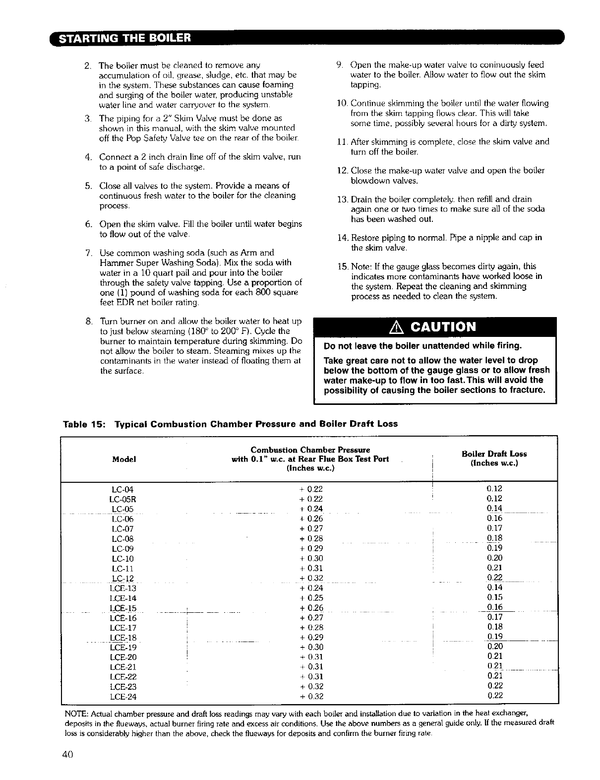
2.
3.
4.
5.
6.
7.
8.
The boiler must be cleaned to remove any
accumulation of oil, grease, sludge, etc. that may be
in the system. These substances can cause foaming
and surging of the boiler water, producing unstable
water line and water carryover to the system.
The piping for a 2" Skim Valve must be done as
shown in this manual, with the skim valve mounted
off the Pop Safety Valve tee on the rear of the boiler
Connect a 2 inch drain line off of the skim valve, run
to a point of safe discharge.
Close all valves to the system. Provide a means of
continuous fresh water to the boiler for the cleaning
process.
Open the skim valve. Fill the boiler until water begins
to flow out of the valve.
Use common washing soda (such as Arm and
Hammer Super Washing Soda). Mix the soda with
water in a 10 quart pail and pour into the boiler
through the safety valve tapping. Use a proportion of
one (1) pound of washing soda for each 800 square
feet EDR net boiler rating.
Turn burner on and allow the boiler water to heat up
to just below steaming (180 ° to 200 ° F). Cycle the
burner to maintain temperature during skimming. Do
not allow the boiler to steam. Steaming mixes up the
contaminants in the water instead of floating them at
the surface.
9. Open the make-up water valve to coninuously feed
water to the boiler, Allow water to flow out the skim
tapping.
10. Continue skimming the boiler until the water flowing
from the skim tapping flows clear. This will take
some time, possibly several hours for a dirt_ system.
11. After skimming is complete, close the skim valve and
turn off the boiler.
12. Close the make-up water valve and open the boiler
blowdown valves.
13. Drain the boiler completely, then refill and drain
again one or two times to make sure all of the soda
has been washed out.
14. Restore piping to normal. Pipe a nipple and cap in
the skim valve.
15. Note: If the gauge glass becomes dirty again, this
indicates more contaminants have worked loose in
the system. Repeat the cleaning and skimming
process as needed to clean the system.
Do not leave the boiler unattended while firing.
Take great care not to allow the water level to drop
below the bottom of the gauge glass or to allow fresh
water make-up to flow in too fast.This will avoid the
possibility of causing the boiler sections to fracture.
Table 15: Typical Combustion Chamber Pressure and Boiler Draft Loss
Combustion Chamber Pressure Boiler Draft Loss
Model with 0.1" w.c. at Rear Flue Box Test Port (Inches w.c,)
(Inches w.c.)
I0.12
0.12
0.14
LC-04
LC-05R
LC-05
LC-06
LC-07
LC-08
LC-09
LC-10
LC-11
LC 12
LCE-13
LCE-14
LCE-15
LCE-16
LCE-17
LCE-18
LCE-19
LCE-20
LCE-21
LCE-22
LCE-23
LCE-24
+ 0,22
+ 0.22
+ 0.24
+ 0.26
+ 0.27
+ 028
+ 029
+ 0.30
+ 0.31
+ 0,32
+ 0.24
+ 0.25
+ 0.26
0.16
0.17
0.18
0.19
0.20
0.21
0.22
0,14
0.15
. 0.16
+ 0,27
+ 0.28
+ 0.29
+ 0.30
+031
+0.31
+ 0.31
+ 0.32
+ 0.32
0.17
0.18
0.19
0.20
0.21
0.21
0.21
0.22
0.22
NOTE: Actual chamber pressure and draft loss readings may vary with each boiler and installation due to variation in the heat exchanger,
deposits in the flueways, actual burner firing rate and excess air conditions, Use the above numbers as a general guide only. If the measured draft
loss is considerably higher than the above, check the flueways for deposits and confirm the burner firing rate
4O
Do not store or allow combustible or flammable
materials near the boiler. Substantial fire or explosion
hazard could result, causing risk of personal injury,
death or property damage.
Do not use this boiler if any part of it has been under
water. Immediately call a qualified service technician
to inspect the boiler. Any part of the control system,
any gas control or any burner or gas component
which has been under water must be replaced.
Should overheating occur or the fuel supply fail to
shut off: Shut off the fuel supply at a location
external to the boiler. Do not turn off or disconnect
the electrical supply to the pump. Immediately call a
qualified service technician to inspect the boiler for
damage and defective components.
f.*1 I'=llF_*l_]l=_[e I:[*]ll:l:f Ih_l [*]',I=I;__'_I[*]L_
I. Start up the Burner/Boiler per the Burner Manual
and the instructions in this manual on starting the
boiler. loll hVjr:lh_//_L_rI, IL_[_l_ ,V:IL_h_IlY:I
2. Prove the correct operation of all controls on the
boiler and burner as outlined below.
3. Check the operation of the ignition and flame
proving controls as described in the Burner Manual.
4. Test the limit and operating controls to assure they
are operating correctly.
5. Inspect and test all low water cutoffs.
6. Test the pop safety valve(s) using the procedure
given by the valve manufacturer on the valve tag.
7. Visually inspect the burner and pilot flames (if
applicable).
I:H b(e] _:LIiIlllol_,_lb,'lli:l_ I:{o]llq;
1. Turn off Burner.
2. Open main line power disconnect switch to
boiler/burner.
3. Close fuel shut-off valves.
4. To take boiler out of service if the boiler and system
are not to be used when temperatures are below
freezing:
a) Drain the boiler and system completely and shut
off make-up water supply.
b) Open main line power disconnect switch to
boiler/burner. Remove the fuses or secure the
switch so that the power cannot be turned on
accidentally.
c) Do not use ethylene glycol antifreeze in a steam
boiler or system.
d) Be certain that the boiler and system are refilled
before returning to service. Follow the
Instructions in the manual and the Lighting
instructions to operate.
Before servicing the boiler:
•Turn off all electrical power to the boiler.
•Close the Gas Service Valve and Oil Shut-Off Valve.
•Allow the boiler to cool if it has been operating.
•Label all wires prior to disconnection when
servicing controls. Wiring errors can cause
improper and dangerous operation, Verify proper
operation after servicing,
1.
2.
3.
4.
Before the start of each heating season, inspect
and make all necessary adjustments to insure proper
boiler and burner operation. Use the maintenance
and inspection procedures following.
Inspect the Venting System
a) Check the chimney or vent to make sure it is
clean and free from cracks or potential leaks.
b) All joints must be tight and sealed.
c) The vent connector must extend into, but not
beyond the inside edge of the chimney or vent.
Inspect the Boiler Area
a) The boiler area must be clean and free from
combustible materials, gasoline or any other
flammable liquids or vapors.
b) The combustion air openings and the area
around the boiler must be unobstructed.
Inspect boiler flueways and burner for cleanliness. If
cleaning is required, use the following procedure.
a) Turn off all electrical power to the boiler.
b) Remove Jacket Middle Front Panel and Jacket
Top Panels. Remove Front Cleanout Plate and
Cleanout Cover Plates on each flueway. On LCE
boilers, remove the top flue outlet plate and vent
piping as necessary to access the top of the
sections.
e) Brush the boiler tube spaces both horizontally
(through cleanout openings on ends) and
vertically (from top of boiler through cleanout
openings at flueways).
41
!::lq I e7,_11k"m LvjF±I I L_/ | _ L__:1 _ [o4
5.
6.
7.
d_
e)
Remove the Burner and Burner Mounting Plate.
Remove any scale or soot from the combustion
chamber by means of vacuum cleaning or other
available means. Take care not to damage the
chamber floor liner or target wall liner.
Replace the Front Cleanout Plate, Burner
Mounting Plate, Burner and all Cleanout Cover
Plates on top of the sections. Make sure all
sealing rope and seals are in good condition.
Replace sealing rope if necessary.
f) Replace all Jacket Panels.
Inspect the boiler and piping for signs of leaks.
Check to see if there are signs of heavy make-up
water addition to the system.
When placing boiler into operation, follow Burner
Manual, all instructions supplied with the boiler and
the instructions in this chapter.
Test the operation of all limit controls, float controls
and ignition components as described in Part A,
"Placing Boiler in Operation", of this chapter.
i. Inspect the boiler area to make sure the area is free
from combustible or flammable materials and that
there are not obstructions to the flow of air to the
boiler or combustion air openings to the room.
2. Make sure there are no signs of abnormal operation,
such as overfilling or leakage.
Be very careful when adding water to a hot boiler,
Add very slowly or, if possible, allow the boiler to
cool naturally before adding water.
If an excessive loss of water occurs, check for a leak
in the piping and correct the problem. Excessive
make-up water will cause corrosion and damage to
the boiler.
!e]q hVj[o]L_||'lk'd ILVJF_,Ih_i|_L1F_,IL_[a4
1.
2.
3.
Inspect the burner and pilot flames as for the annual
inspection.
Inspect the boiler and system for any signs of
leakage or excessive make-up water usage.
Inspect and check the operation of the venting
system.
42
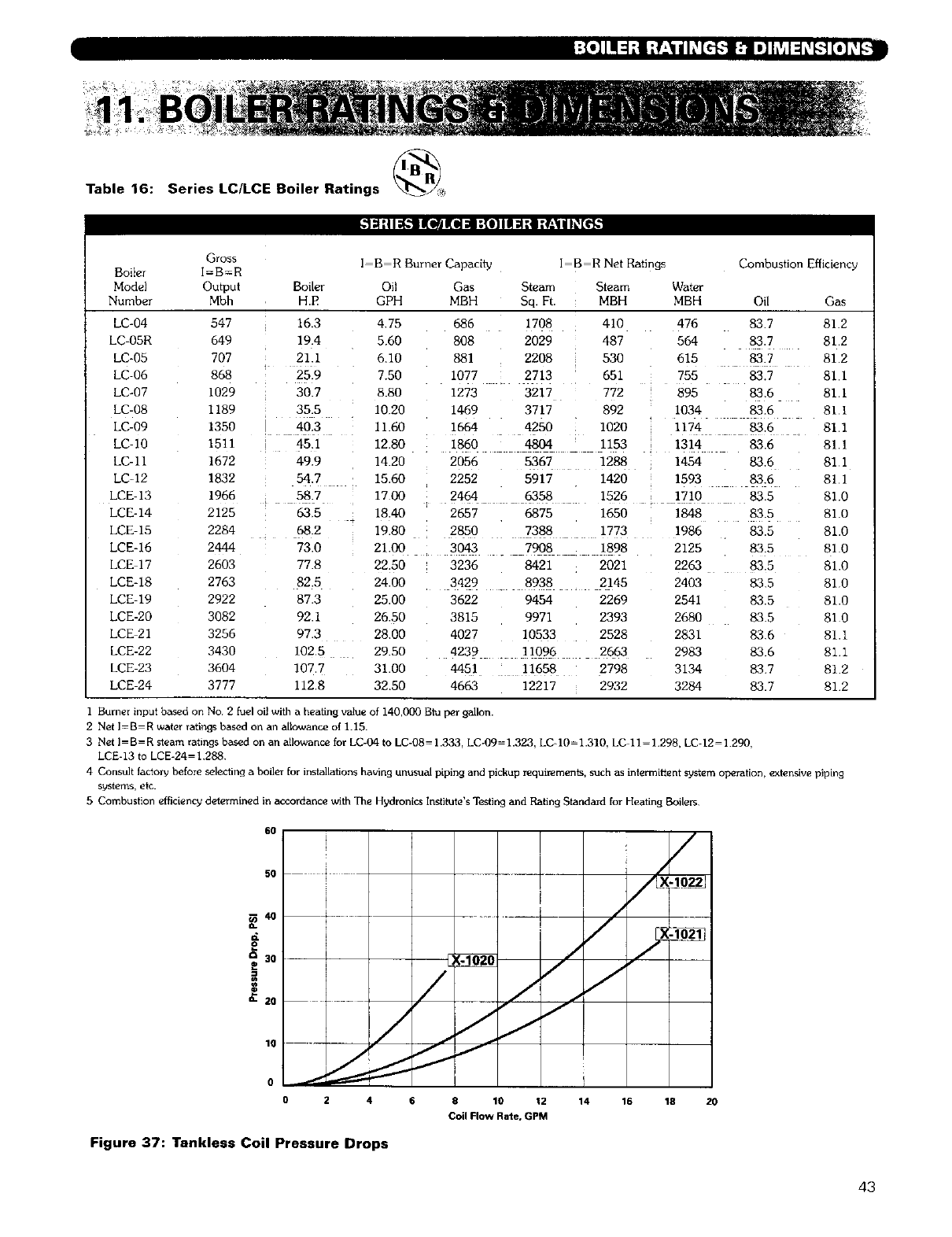
Table 16: Series LC/LCE Boiler Ratings
-'1_:11_.'II I(l_JKil =1 :(011i 1:tl :q:_ | I_[€_
Gross
Boiler I=B=R
Model Output
Number Mbh
LC-04 547
LC-O5R 649
LC=05 707
LC-06 868
LC-07 1029
LC-08 1189
LC-09 1350
LC-10 1511
LC-11 1672
LCd2 1832
LCE 13 1966
LCE-14 2125
LCE-15 2284
LCE-16 2444
LCE 17 2603
LCE-18 2763
LCE-19 2922
LCE-20 3082
LCE 21 3256
LCE-22 3430
LCE-23 3604
LCE 24 3777
Boiler
H.P
l B R Burner Capacity I B R Net Ratings Combustion Efficiency
Oil Gas Steam Steam Water
GPH MBH Sq. Ft MBH MBH Oil Gas
16.3
19.4
21.1
t25_9
30.7
35.5
i4o:3
; 45.1
49.9
54.7 :
i 58.7
63,5
68.2
73.0
77.8
82.5
87.3
92.1
97.3
1025
107.7
112.8
475 686 1708 410 476 837 81.2
560 808 2029 487 564 83.7 81.2
6.10 881 2208 530 615 83.7 81.2
7.50 1077 2713 651 755 83.7 81.1
8.80 1273 3217 772 895 83.6 81.1
1020 1469 3717 892 1034 83.6 811
II.60 1664 4250 1020 1174 83.6 81.1
12.80 1860 4804 1153 1314 83.6 81.1
14.20 2056 5367 1288 1454 83.6 811
15.60 2252 5917 1420 1593 83.6 811
1700 2464 6358 1526 1710 83.5 81.0
18.40 2657 6875 1650 1848 83.5 81.0
19.80 2850 7388 1773 1986 83.5 81.0
21.00 3043 7908 1898 2125 83.5 810
22.50 3236 8421 2021 2263 83.5 81.0
24.00 3429 8938 2145 2403 83.5 810
25.00 3622 9454 2269 2541 83.5 81.0
26.50 3815 9971 2393 2680 83.5 81 0
2800 4027 10533 2528 2831 836 81.1
29.50 4239 11096 2663 2983 83.6 811
31.00 4451 11658 2798 3134 83.7 812
32.50 4663 12217 2932 3284 83.7 812
I Burner input based on No 2 fuel oil with a heating value of 140,000 Blu per gallon.
2 Net I=B-R water ratings based on an allowance of 1.15.
3 Net I-B-R steam ratings based on an allowance for LC-04 to LC-08= 1.333, LC-09=1.323, LC-10=I.310, LC 11-1.298, LC-12-1 290,
LCE-13 to LCE-24-1 288.
4 Consult factory before selecting a boiler for installations having unusual piping and pickup requirements, such as intermitient system operation, extensive piping
systems,etc.
5 Combustion efficiency determined in accordance with The Hydronics Instgute's Testing and Rating Standard for Heating Boilers
6O
5O
4O
Q..
o
a30
==
10
i.. .
J
I
//
/ //
/
2 6 8 10 12
I
14 16 18
Coil Flow Rate, GPM
Figure 37: Tankless Coil Pressure Drops
/
2O
43
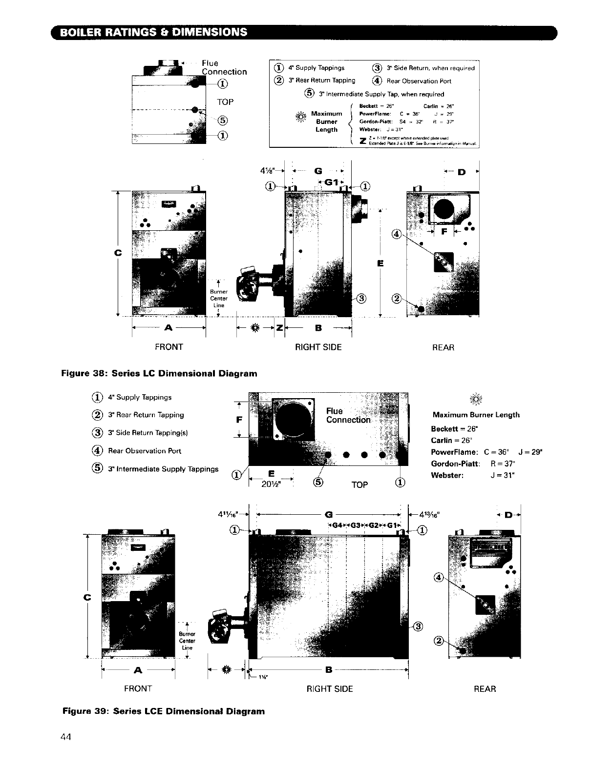
-IT[,]IIII ::1;]IT_'__dT_[_._ [_ t_bSl :l_-_]J[O]__-_]
Flue
Connection
TOP
®
(_) 4" Supply Tappings (_) 3" Side Return, when required
(_) 3" Rear Return Tapping (_ Rear Observation Port
(_ 3" Intermediate Supply Tap, when required
tBecket t = 26" Cartin = 26"
Maximum PowerFlame: C = 36" J=29=
Burner Gordon-piat_: $4 = 32" R = 37 _
Length Webster: J = 31"
Z = t 1f_ excep_whe,e e_eqd=d plate _d
Z E_end_Flate J_S6 i_ Se_Burne[info_ationmMan_al
C
FRONT RIGHT SIDE REAR
Figure 38: Series LC Dimensional Diagram
(_ 4" Supply Tappings
(_) 3" Rear Return Tapping
(_ 3" Side Return Tapping(s)
(_ Rear Observation Port
(_ 3" Intermediate Supply Tappings
F
••
TOP
Maximum Burner Length
Beckett = 26"
Carlin = 26"
PowerFlame: C = 36" J= 29"
Gordon-Piatt: R - 37"
Webster: J = 31"
C
Line
FRONT
Figure 39: Series LCE Dimensional Diagram
G
B
RIGHT SIDE REAR
44
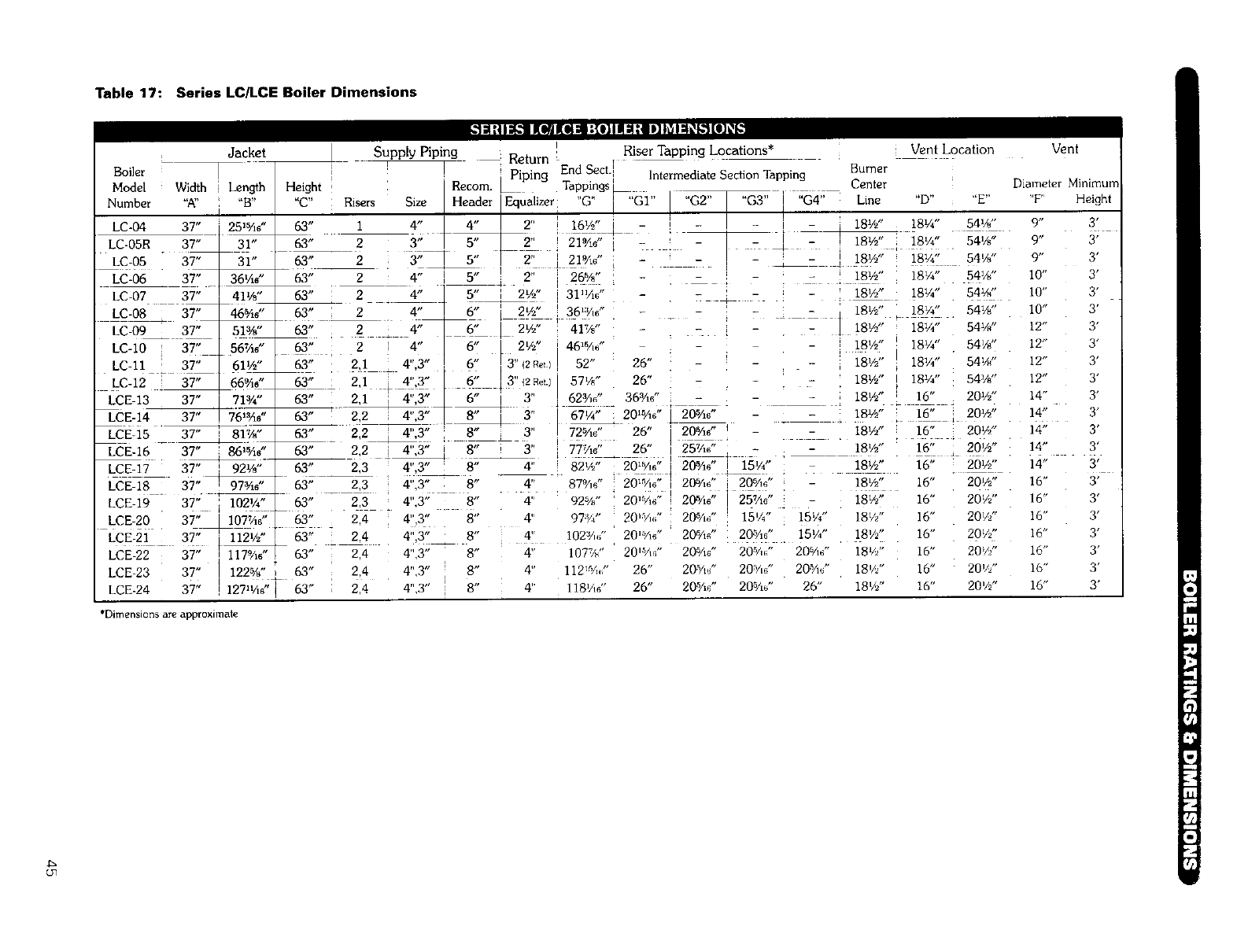
Table 17: Series LC/LCE Boiler Dimensions
Boiler
Model
Number ",K'
LC-04
LC-05R
LC-05
LC-06
LC-07
LC-08
LC-09
LC-IO l
LC-I1 T
LC-12
LCE-13
LCE-14
LCE-15
LCE-16
Jacket Supply Piping
Height '
"C" : Risers
Width i Length
Size HeaderEqualizer"0" l "Gr' I"02.... G3" i "G4" Line "D.... E"
,t t, . i I ,t i
4/4216_ + - - ti 18½" 18¼" 54w'
3" _ _2'_ ) 21'/1." i 7 ! - _ _ _ 1 18_'_" i _8¼" 54%"
3" T s" ] 2" ] t! °/1¢' - 7 , - Z = I !8'/_" _812o" p4v_"
- 18t/2 18/4 54/8
4" i 5" I_ 2" i 26%" - _ ! , l 1-
4" T 5" i 2½" i 31hAd' - - - 18W' 181/,*" 54V/'
4" 6" 2½" ! 36'Ym" _ - 7_ q 18½" 18¼" 541//'
- - ] 18W" 18¼" 541/d '
1-1iI I,,t-i ,_-TI,%wlI *|',| l ¶ ?t| -d•u,-'*"." LO]_h"
I
Return _ , Riser Tapping Locations* Vent Location Vent
Lp End Sect. I Burner
Recom. iping Tappings _ Intermediate Section Tapping Center Diameter Minimum
'rF' Height
I 18½"
:181/2,,
i
v. 18½"
--,18½" !
18½"
-18½"
18¼" 54_"
18¼" 54_"
18¼" 54¼"
16" 20½"
16" i 20½"
16" _ 20½"
63" 1
63" 2
63" 2 i
63" 2
63" 2
63" i 2
63" 2
63" 2 i 4"
63" 2,1 4",3" ,
63_ : 2,1 i 4",3"
63" 2,1 4",3"
63" ! _ 4",3"
63" 2,2 _ 4",3"
4" 6" [ 2½" 41%" =
6" 2%, 46_V,d '
6" / 3" (2R_t) I52" 26"
6" [ 3" 12net.) 57%" 26"
6" i3" 62aAa" 36V_d'
8" _ 3" I67¼" 2015A6 " ]205A6"
8" 3" , 72:A_:', _ 26" i 2o_/,o",
8" I 77V,# 26" i 25¼g ' _i 3" 18½" 16" 20½"
16" 20½"
16" 20½"
16" 20V_"
16" 201/z"
16" 20Vz"
16" 20V/'
16" 20V/'
16" 20½"
i "B"
I
37" '251_d '
37" 31"
37" 31"
37" 36¼g'
37" 41½"
37" 46%d"
37" 51%"
37" 56%d"
37" 61½"
37" 66_0"
37" _71¾"
37" _61_6"
37" T 81%"
L
37" i 861%6"
LCE-17 37" ! 92½"
LCE18- 37"_ 97¾d'
LCE-19 37" ' 102¼ _ 63"
LCE 20 3T_107Vm" 63"
LCE-21 37" _ 63"
LCE-23 37" I 122%' _,_ 63"
LCE-24 37" !127_¼_" 63"
9,, 31
63" 2,2 i 4",3"
63 H
63" _ 2,3 4",3" _ 8" 4" 87%0" 20_Y,o" I 2_Ad' _ 20_Ad" "
23 4",3" 8" "4" 92%" 20 ¼_•;' 20_Ad' ]25Vld' -
2,4 4",3" 8" 4" 97:k7' 2@_A_(' 20_A6" 15W' 15¼"
2,4 4",3" 8" 4" 102:V./' 20'V_d' 20V_d' 20"%_" 15¼"
2,4 4",3" 8" 4" 107%" 20'aA/' 20SAd'20 _/,_" 20 sad'
2,4 4",3" 8" 4" 112_%." 26" 20rV_"20V.(' 20_7_d'
2,4 4",3" 8" 4" 118¼# 26" 20%_" 20.%J 26"
2,3 4",3" 8" 4" 82½ 20 5/16 i20_Ad 'i15¼" 181/2"
18½"
18½"
18///'
18½"
181/2 "
18'//'
18½"
9. 3,
9" 3'
10" 3'
10" 3'
10" 3'
12" 3'
12" 3'
12" 3'
12" 3'
14" 3'
14" 3'
14" 3'
14" 3'
14" 3'
16"
16"
16"
16"
16"
16"
16"
3,
3'
3'
3'
3'
3'
3'
*Dimensionsareapproximate
tan

3
25
I
8
21
.f
_3i
'7 0_
o _o_
.. _-_ '-_
_._.
o-
g .
0 . 0
g _ .
_.-©
o o _
__ _5'
z _
ca- r
_.('3
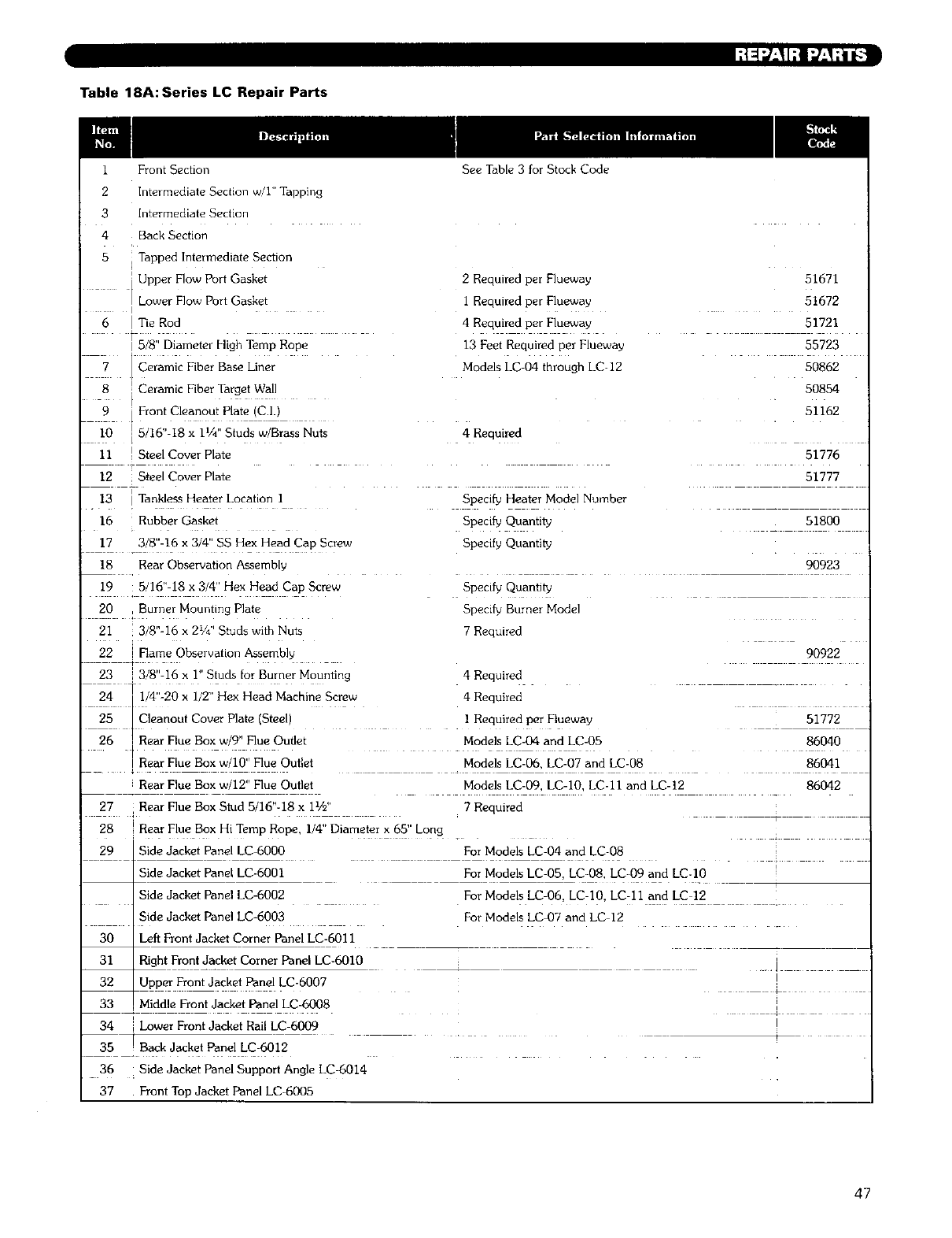
L_:I;/-_ If] i_-,_'ii-"]-
Table 18A:Series LC Repair Parts
I Front Section
2Intermediate Section w/1 '_Tapping
See Table 3 for Stock Code
3Intermediate Section
4 Back Section
5 Tapped Intermediate Section
i
'Upper Flow Port Gasket
Lower Flow Port Gasket
I
6 [ Tie Rod
I 5/8" Diameter High Temp Rope
[ Ceramic Fiber Base Liner
t
i. .
8:Ceramic Fiber Target Wall
_ 9 I Front € eanou! P!a!e !c.I.
I0 ] 5/16" 18 x 11/4"Studs w/Brass Nuts
11 I Steel Cover Plate
12 Steel Cover Plate
I
13 I Tankless Heater Location I
16 Rubber Gasket
17 3/8"-16 x 3/4" SS Hex Head Cap Screw
18 Rear Observation Assembly
19 5/16" 18 x 3/41' Hex Head Cap Screw
20 I Burner Mounting Plate
21 : 3/8"-16 x 21/4.' Studs with Nuts
22 i Flame Observation Assembly
±
2 Required per Flueway
I Required per Flueway
4 Required per Flueway
13 Feet Required per Flueway
Models LC-04 through LC-12
4 Required
Specif_ Heater Model Number
Specify Quantity
Specify Quantity
Specify Quantity
Specdy Burner Model
7 R_'guirQd
51671
51672
51721
55723
50862
50854
51162
51776
51777
51800
90923
90922
23 3 8 -16 x I Studs for Burner Mounting 4 Required
24 [ I/4'-20 x I/2" Hex Head Machine Screw 4 Required
I
25 I Cleanout Cover Plate (Steel) I Required per Flueway 51772
J
26 0 t Models LC-06 LC-07 and LC-08 86041
Rear Flue Box w/12" Flue Outlet Models LC-09. LC-10 LC-II and LC-12 86042
27 ,Rear Flue Box Stud 5/16"-18 x 11/2'' 7 Required
28 Rear Flue Box Hi Temp Rope, I/4" Diameter x 65" Long
29 Side Jacket Panel LC 6000 For Models LC-04 and LC-08
+
Side Jacket Panel LC-6001 For Models LC-05 LC-08. LC-09 and LC-10
Side Jacket Panel LC-6002 For Models LC-06, LC-10. LC-II and LC 12
For Models LC 07 and LC 12Side Jacket Panel LC-6003
F
30 [Left Front Jacket Corner Panel LC-6011
i
_ Right Front Jacket Corner Panel LC-6010
_2_Upper Front Jacket Pane! LC-6007
33 ! Middle Front Jacket Panel LC-6008
34 i Lower Front Jacket Rail LC 6009
)
35 ! Back Jacket Panel LC-6012
36 Side Jacket Panel Support Angle LC-6014
37 Front Top Jacket Panel LC-6005
47
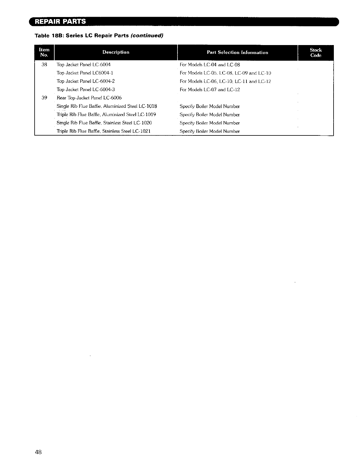
I;1=]_'-_I.qI",7_'_;tl_'_
Table 18B: Series LC Repair Parts (continued)
38 Top Jacket Panel LC 6004
Top Jacket Panel LC6004 1
Top Jacket Panel LC 6004 2
Top Jacket Panel LC-6004-3
39 Rear Top Jacket Panel LC-6006
Single Rib Flue Baffle, Aluminized Steel LC-I018
Triple Rib Flue Baffle, Aluminized Steel LC-I019
Single Rib Flue Baffle, Stainless Steel LC 1020
Triple Rib Flue Baffle, Stainless Steel LC 1021
For Models LC-04 and LC 08
For Modds LC 05. LC 08, LC-09 and LC 10
For Models LC-06, LC 10. LC 11 and LC-12
For Models LC-07 and LC-12
Specify Boiler Model Number
Specify Boiler Model Number
Specify Boiler Model Number
Specify Boiler Model Number
48
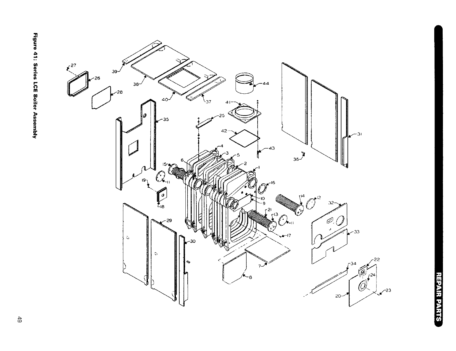
t_
II
I-'
Im
O I
l'l
,,.i
m
3
_3t
30
/
4_
_.0
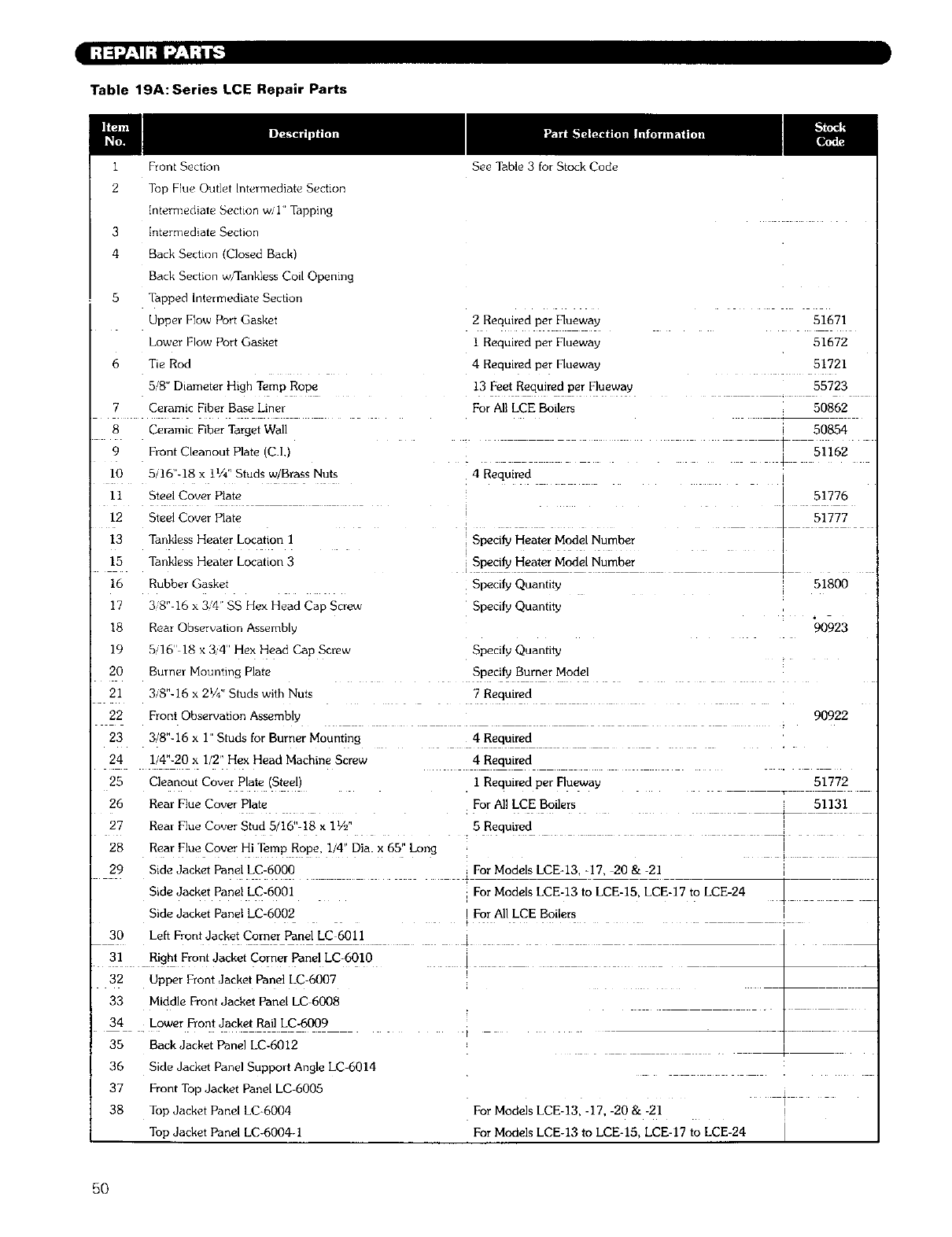
Table 19A:Series LCE Repair Parts
Front Section See Table 3 for Stock Code
2 Top Flue Outl#t Inteml#dlat¢, S_'ctlon
intermediate Sechon w/1 Tapping
[ntermedlate Section
4 Back Sertlon Closed Back
Back Section _/Tankless Cod Opening
5Tapped Intermediate Section
Upper Flow Port Gasket
Lower Flow Port Gasket
2 Required per Flueway 51671
i Required per Flueway 51672
6 Tie Rod
5/8" Diameter High Temp Rope
7 Ceramic Fiber Base Liner
8 Ceramic Fiber Target Wall
9 Fiont Cleanout Plate (C.I,
I0 5/161'-18 x ii/4 Studs w Brass Nuts
11 Steel Cover Plate
12 Steel Cover Plate
13 Tankless Heater Location I
4 Required per Flueway 51721
13 Feet Required per Flueway 55723
For All LCE Boilers 50862
50854
51162
4 Required
Specify Heater Model Number
51776
L 51777
15 Tankless Heater Location 3 Specify Heater Model Number
16 Rubber Gaskel Specify Quantity 51800
17 3 8'-16 x 3,4' SS Hex Head Cap Screw Specify Quantity
18 Rein Obs_rvatlon Assembly 90923
]9 5116 18 x 34' Hex Head Ca]; Screw Specdy Quantity
20
21
22
23
24
25 Cleanout Cover Plate Steell
Burn_1 Mounting Plate Specify Burner Model
3/8"-16 x 21/4'' Studs with Nuts 7 Required
Front Observation Assembly 90922
3/8"-16 x I' Studs for Burner Mounting 4 Required
1/4"-20 x I/2' Hex Head Machine Screw 4 Required
I Required per Flueway 51772
26 Rear Flue Cover Plate
27 Real Flue Covel Stud 5 16"-18 x lY2'
28 Rear F _e Cover Hi Temp Rope. I 4" Dia. x 65" Long
29 Side Jacket Panel LC-6000
Bide Jacket Panel LC-6001
Side Jacket Panel LC-6002
30 Left Front Jacket Corner Panel LC 6011
For All LCE Boilers 51131
5 Required
For Models LCE-13 -17. 20 & -21
For Models LCE-13 to LCE-15. LCE-17 to LCE-24
For All LCE Boilers
I
31 Right Front Jacket Corner Panel LC-601O 1__
32 Upper Front Jacket Panel LC-6007
33 Middle Front Jacket Panel LC 6008
34 . Lower Front Jacket Rail LC-6009
35 Rack Jacket Panel LC-6012
36 Side Jacket Panel Support Angle LC-6014
37 Front Tol: Jacket Panel LC-6005
38 ToI_ Jacket Panel LC-6004 For Models LCE-12 -17. -20 & -21
Top Jacket Panel LC-6004-I For Models LCE-13 to LCE-15, LCE-17 to LCE-24
5O
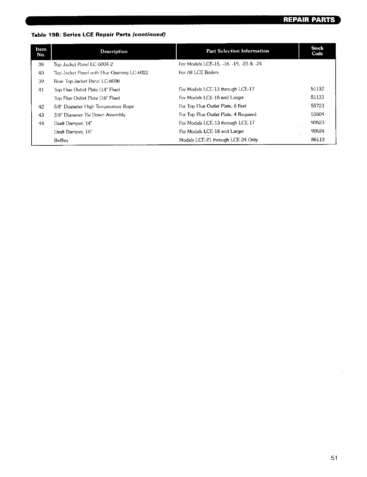
Table 19B: Series LCE Repair Parts (continued)
38 Top Jacket Panel LC-6004-2
40 Top ,Jacket Panel with Flue Opening LC-6022
39 Rear Top Jacket Panel LC-6006
41 Top Flue Outlet Plate (14" Flue)
Top Flue Outlet Plate (16" Flue)
42 5/8" Diameter High T_,mperature Rope
43 3/81' Diameter Tie Down Assembly
44 Draft Damper, 14"
Draft Damper, 16"
Baffles
For Models LCE-15, -16, -19, 23 & 24
For All LCE Boilers
For Models LCE-13 through LCE-17
For Models LCE 18 and Larger
For Top Flue Outlet Plate, 6 Feet
For Top Flue Outlet Plate, 4 Required
For Models LCE-13 through LCE 17
For Models LCE-18 and Larger
Models LCE-21 through LCE-24 Only
51132
51133
55723
51604
90523
90524
86113
51

Series LC/LCE
Oil, Gas Gas/Oil Boilers
Steam
Installation,
Operation
Maintenance
Manual
TO THE INSTALLER:
This manua/ is the property of the owner and must
be affixed near the boifer for future reference,
TO THE OWNER:
This boiler should be inspected annuafly by a
Quafiffed Service Agency.
member gama
HI Division ASME
of gama
PEERLESS °
CAST IRON BOILERS
PEERLESS HEATER COMPANY
231 NORTH WALNUT STREET •BOYERTOWN, PA 19512-1021 •PHONE 610 367 2153
www, peerless-heater.oom
THE PREFERRED HEATING CHOICE
@2002 Peerless Heater Company LC8046 R1 (12/02-1M)
Printed in U.S.A.
