PEGATRON CLG8202-NA Wireless Home Automation and Security User Manual 78 100422 01A0 indd
PEGATRON CORPORATION Wireless Home Automation and Security 78 100422 01A0 indd
PEGATRON >
Contents
- 1. User Manual
- 2. User Manual Statement
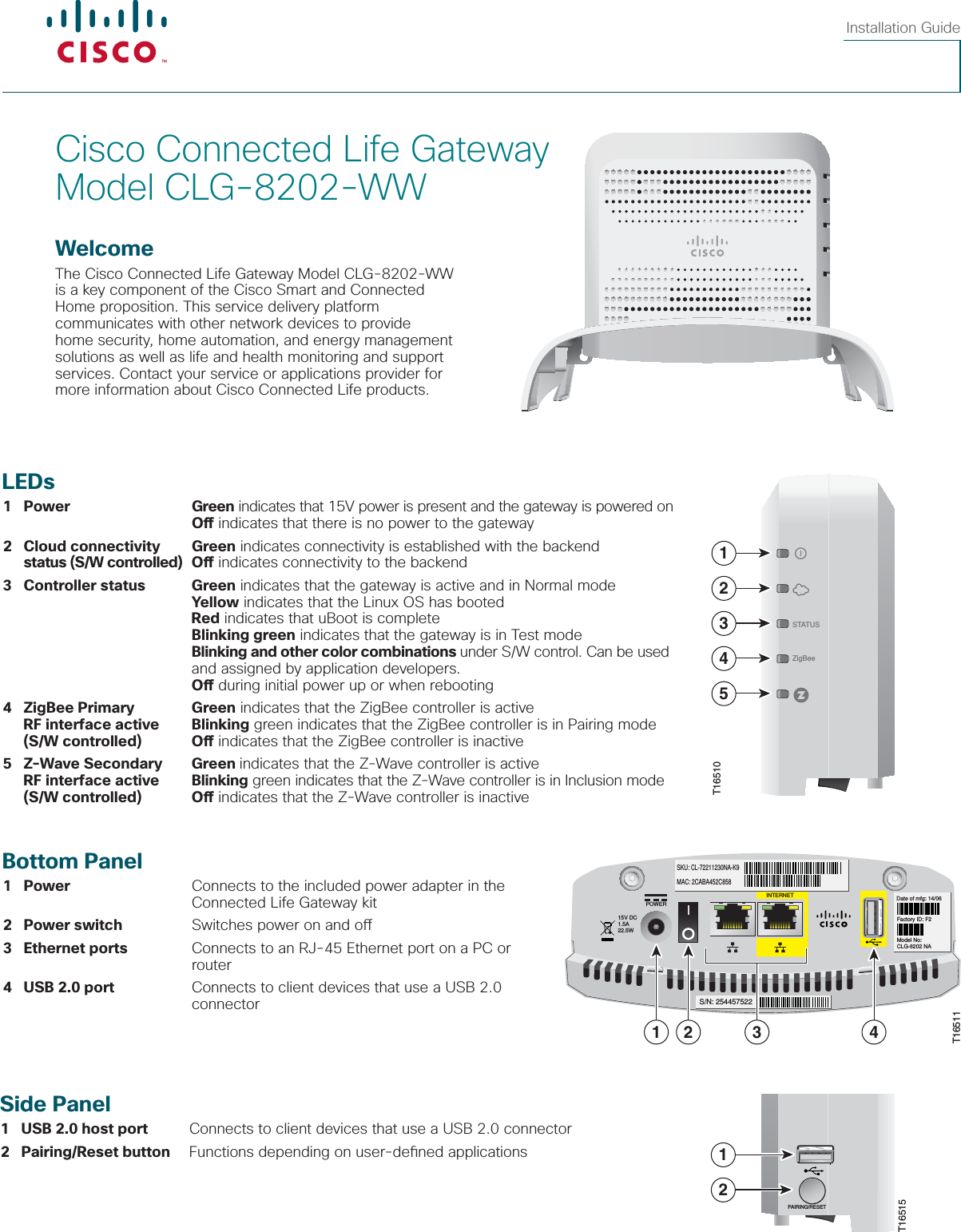
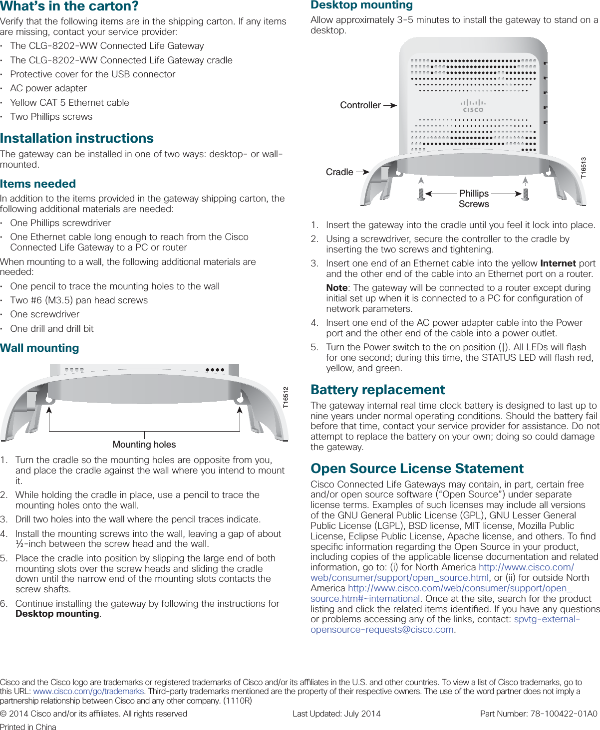
User Manual