PEGATRON DPC3941 WIRELESS RESIDENTIAL VOICE GATEWAY User Manual
PEGATRON CORPORATION WIRELESS RESIDENTIAL VOICE GATEWAY
UserManual.wiki
>
PEGATRON
>
DPC3941 User Manual
User Manual
Navigation menu
Upload a User Manual
Namespaces
Wiki Guide
HTML
PDF
Info
Views
User Manual
Discussion / Help
Navigation


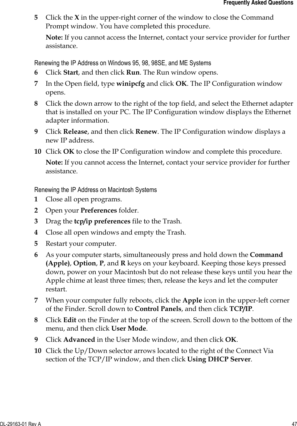
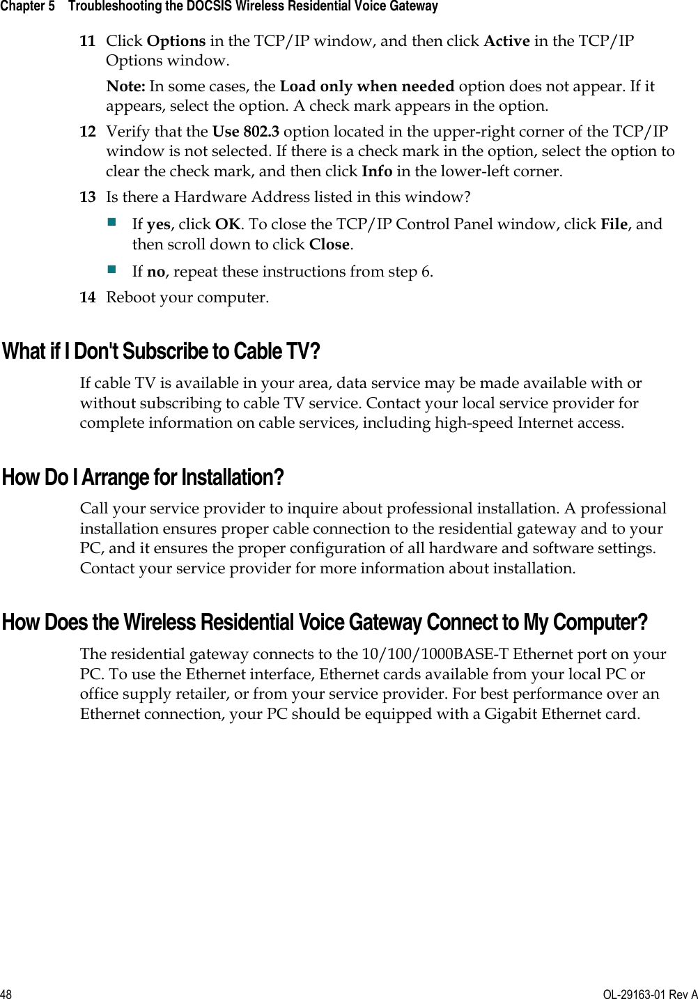
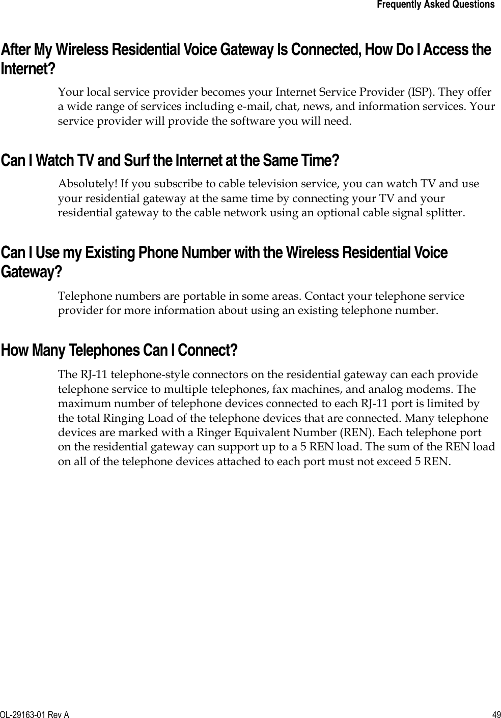
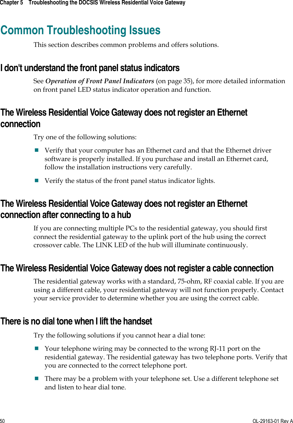
![Chapter 2 Installing the DOCSIS Wireless Residential Voice Gateway 30 OL-29163-01 Rev A Section Field Description Manually Added WiFi Devices This section allows the user to add WiFi client into the WiFi Control List. Enter the MAC address of the device and select a name for it and click “ADD.” Add WPS Client This page allows user to manually set up and connect WPS clients, WPS PIN method and Push Button. Section Field Description SSID Use this section to select which SSID would like to be selected to connect a client to using WPS. WiFi Protected Setup (WPS) This section allows the user to enable/disable WPS mechanism. WPS PIN Method This section allows the user to enable/disable the WPS PIN Method. Connection Options User can select to use Push Button method or PIN Method connection. In PUSH Button mode, click PAIR after the client has asked WPS button to be pushed. Wireless Clients PIN To pair, select the Pair button and your wireless device will connect within two minutes. You may also press the [push] button on this device. The Wireless Clients PIN, found from client, needs to be entered in this field and click PAIR](https://usermanual.wiki/PEGATRON/DPC3941/User-Guide-2210986-Page-46.png)