PEGATRON DPC3941 WIRELESS RESIDENTIAL VOICE GATEWAY User Manual
PEGATRON CORPORATION WIRELESS RESIDENTIAL VOICE GATEWAY
PEGATRON >
User Manual

OL-29163-01 Rev A
Cisco Model DPC3941 DOCSIS
3.0 16x4 Wireless Residential
Voice Gateway
User Guide
Please Read
Important
Please read this entire guide. If this guide provides installation or operation
instructions, give particular attention to all safety statements included in this guide.
Notices
Trademark Acknowledgments
Cisco and the Cisco logo are trademarks or registered trademarks of Cisco and/or its
affiliates in the U.S. and other countries. To view a list of Cisco trademarks, go to this
URL: www.cisco.com/go/trademarks. DOCSIS is a registered trademark of Cable
Television Laboratories, Inc. EuroDOCSIS, EuroPacketCable, and PacketCable are
trademarks of Cable Television Laboratories, Inc. The Wi-Fi Protected Setup mark is
a mark of the Wi-Fi Alliance. Wi-Fi Protected Setup is a trademark of the Wi-Fi
Alliance.
Other third party trademarks mentioned are the property of their respective owners.
The use of the word partner does not imply a partnership relationship between
Cisco and any other company. (1110R)
Publication Disclaimer
Cisco Systems, Inc. assumes no responsibility for errors or omissions that may
appear in this publication. We reserve the right to change this publication at any
time without notice. This document is not to be construed as conferring by
implication, estoppel, or otherwise any license or right under any copyright or
patent, whether or not the use of any information in this document employs an
invention claimed in any existing or later issued patent.
Disclaimer
The maximum performance for wireless is derived from IEEE Standard 802.11
specifications. Actual performance can vary, including lower wireless network
capacity, data throughput rate, range and coverage. Performance depends on many
factors, conditions and variables, including distance from the access point, volume of
network traffic, building materials and construction, operating system used, mix of
wireless products used, interference and other adverse conditions.
Software and Firmware Use
The software described in this document is protected by copyright law and
furnished to you under a license agreement. You may only use or copy this software
in accordance with the terms of your license agreement.
The firmware in this equipment is protected by copyright law. You may only use the
firmware in the equipment in which it is provided. Any reproduction or distribution
of this firmware, or any portion of it, without our express written consent is
prohibited.
Copyright
© 2013 Cisco Systems, Inc. All rights reserved. Printed in the United States of
America.
Information in this publication is subject to change without notice. No part of this
publication may be reproduced or transmitted in any form, by photocopy,
microfilm, xerography, or any other means, or incorporated into any information
retrieval system, electronic or mechanical, for any purpose, without the express
permission of Cisco Systems, Inc.
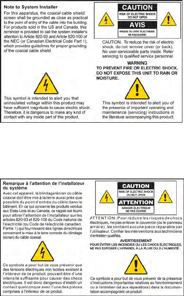
Notice to Installers
The servicing instructions in this notice are for use by qualified service personnel only. To reduce the
risk of electric shock, do not perform any servicing other than that contained in the operating
instructions, unless you are qualified to do so.
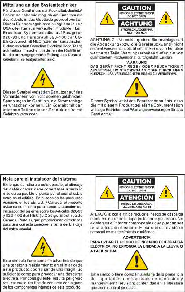
Notice à l’attention des installateurs de réseaux câblés
Les instructions relatives aux interventions d’entretien, fournies dans la présente notice, s’adressent
exclusivement au personnel technique qualifié. Pour réduire les risques de chocs électriques, n’effectuer
aucune intervention autre que celles décrites dans le mode d'emploi et les instructions relatives au
fonctionnement, à moins que vous ne soyez qualifié pour ce faire.
Mitteilung für CATV-Techniker
Die in dieser Mitteilung aufgeführten Wartungsanweisungen sind ausschließlich für qualifiziertes
Fachpersonal bestimmt. Um die Gefahr eines elektrischen Schlags zu reduzieren, sollten Sie keine
Wartungsarbeiten durchführen, die nicht ausdrücklich in der Bedienungsanleitung aufgeführt sind,
außer Sie sind zur Durchführung solcher Arbeiten qualifiziert.
Aviso a los instaladores de sistemas CATV
Las instrucciones de reparación contenidas en el presente aviso son para uso exclusivo por parte de
personal de mantenimiento cualificado. Con el fin de reducir el riesgo de descarga eléctrica, no realice
ninguna otra operación de reparación distinta a las contenidas en las instrucciones de funcionamiento, a
menos que posea la cualificación necesaria para hacerlo.
20080814_Installer820_Intl

OL-29163-01 Rev
A
iii
Contents
IMPORTANT SAFETY INSTRUCTIONS v
United States FCC Compliance x
About This Guide xii
Chapter 1 Introducing the DOCSIS Wireless Residential Voice
Gateway 1
Introduction .............................................................................................................................. 2
What's In the Carton? .............................................................................................................. 4
Front Panel Description .......................................................................................................... 5
Top Panel Description ............................................................................................................. 7
Bottom Panel Description ....................................................................................................... 8
Back Panel Description ............................................................................................................ 9
Chapter 2 Installing the DOCSIS Wireless Residential Voice
Gateway 11
Installation Preparations ....................................................................................................... 12
Install the Wireless Residential Voice Gateway ................................................................ 19
Configure Wireless Settings ................................................................................................. 22
MoCA Installation Guidelines ............................................................................................. 31
Chapter 3 Operation of Front Panel Indicators 35
Initial Power Up, Calibration, and Registration (AC Power applied) ........................... 36
Normal Operations (AC Power Applied) .......................................................................... 38
Special Conditions ................................................................................................................. 39
Chapter 4 Maintaining the Battery 41
Location of the Battery .......................................................................................................... 42
Battery Maintenance .............................................................................................................. 43
Contents
iv OL-29163-01 Rev
A
Chapter 5 Troubleshooting the DOCSIS Wireless Residential
Voice Gateway 45
Frequently Asked Questions ................................................................................................ 46
Common Troubleshooting Issues ........................................................................................ 52
Tips for Improved Performance .......................................................................................... 54
Chapter 6 Customer Information 55

IMPORTANT SAFETY INSTRUCTIONS
OL-29163-01 Rev
A
v
IMPORTANT SAFETY INSTRUCTIONS
1) Read these instructions.
2) Keep these instructions.
3) Heed all warnings.
4) Follow all instructions.
5) Do not use this apparatus near water.
6) Clean only with dry cloth.
7) Do not block any ventilation openings. Install in accordance with the manufacturer's
instructions.
8) Do not install near any heat sources such as radiators, heat registers, stoves, or other
apparatus (including amplifiers) that produce heat.
9) Do not defeat the safety purpose of the polarized or grounding-type plug. A
polarized plug has two blades with one wider than the other. A grounding-type
plug has two blades and a third grounding prong. The wide blade or the third
prong is provided for your safety. If the provided plug does not fit into your outlet,
consult an electrician for replacement of the obsolete outlet.
10) Protect the power cord from being walked on or pinched particularly at plugs,
convenience receptacles, and the point where they exit from the apparatus.
11) Only use attachments/accessories specified by the manufacturer.
12)
Use only with the cart, stand, tripod, bracket, or table specified by the
manufacturer, or sold with the apparatus. When a cart is used, use caution
when moving the cart/apparatus combination to avoid injury from
tip-over.
13) Unplug this apparatus during lightning storms or when unused for long periods of
time.
14) Refer all servicing to qualified service personnel. Servicing is required when the
apparatus has been damaged in any way, such as a power-supply cord or plug is
damaged, liquid has been spilled or objects have fallen into the apparatus, the
apparatus has been exposed to rain or moisture, does not operate normally, or has
been dropped.
Power Source Warning
A label on this product indicates the correct power source for this product. Operate this product only
from an electrical outlet with the voltage and frequency indicated on the product label. If you are
uncertain of the type of power supply to your home or business, consult your service provider or your
local power company.
The AC inlet on the unit must remain accessible and operable at all times.
Ground the Product
WARNING: Avoid electric shock and fire hazard! If this product connects to coaxial
cable wiring, be sure the cable system is grounded (earthed). Grounding provides
some protection against voltage surges and built-up static charges.
IMPORTANT SAFETY INSTRUCTIONS
vi OL-29163-01 Rev
A
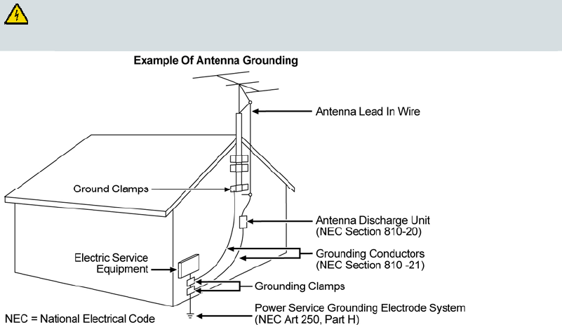
Outdoor Grounding System
If this product connects to an outdoor antenna or cable system, be sure the antenna or cable system is
grounded (earthed). This provides some protection against voltage surges and built-up static charges.
Article 810 of the National Electric Code (NEC) ANSI/NFPA No. 70-1990, provides the following
information:
Grounding of the mast and supporting structure
Grounding the lead-in wire to an antenna discharge unit
Size of the grounding conductors
Location of the antenna-discharge unit
Connection to grounding electrodes
Requirements for the grounding electrodes (see the following antenna grounding diagram as
recommended by NEC ANSI/NFPA 70)
WARNING: Avoid electric shock and fire hazard! Do not locate an outside antenna
system in the vicinity of overhead power lines or power circuits. Touching power lines
or circuits might be fatal.
Protect the Product from Lightning
In addition to disconnecting the AC power from the wall outlet, disconnect the signal inputs.
Verify the Power Source from the On/Off Power Light
When the on/off power light is not illuminated, the apparatus may still be connected to the power
source. The light may go out when the apparatus is turned off, regardless of whether it is still plugged
into an AC power source.
IMPORTANT SAFETY INSTRUCTIONS
OL-29163-01 Rev
A
vii
Eliminate AC Power/Mains Overloads
WARNING: Avoid electric shock and fire hazard! Do not overload AC power/mains,
outlets, extension cords, or integral convenience receptacles. For products that require
battery power or other power sources to operate them, refer to the operating
instructions for those products.
Handling Disposable Batteries
This product may contain a rechargeable Lithium-Ion battery to provide stand-by operation in the
event of an AC power failure.
Heed the following warning, follow the Battery Safety and Battery Disposal instructions below, and see
the instructions later in this guide for handling, replacing, and disposing of the battery.
WARNING: There is danger of explosion if the battery is mishandled or incorrectly
replaced. Replace only with the same type of battery. Do not disassemble it or attempt
to recharge it outside the system. Do not crush, puncture, dispose of in fire, short the
external contacts, or expose to water or other liquids. Dispose of the battery in
accordance with local regulations and instructions from your service provider.
Battery Safety
Insert batteries correctly. There may be a risk of explosion if the batteries are incorrectly inserted.
Do not attempt to recharge ‘disposable’ or ‘non-reusable’ batteries.
Please follow instructions provided for charging ‘rechargeable’ batteries.
Replace batteries with the same or equivalent type that we recommend.
Do not expose batteries to excessive heat (such as sunlight or fire).
Do not expose batteries to temperatures above 100°C (212°F).
Battery Disposal
The batteries may contain substances that could be harmful to the environment.
Recycle or dispose of batteries in accordance with the battery manufacturer’s instructions and
local/national disposal and recycling regulations.
The batteries may contain perchlorate, a known hazardous substance, so special handling and
disposal of this product might be necessary. For more information about perchlorate and best
management practices for perchlorate-containing substance, see
www.dtsc.ca.gov/hazardouswaste/perchlorate

IMPORTANT SAFETY INSTRUCTIONS
viii OL-29163-01 Rev
A
Provide Ventilation and Select a Location
Remove all packaging material before applying power to the product.
Make certain to operate this unit only in a vertical position.
Do not place this apparatus on a bed, sofa, rug, or similar surface.
Do not place this apparatus on an unstable surface.
Do not install this apparatus in an enclosure, such as a bookcase or rack, unless the installation
provides proper ventilation.
Do not place entertainment devices (such as VCRs or DVDs), lamps, books, vases with liquids, or
other objects on top of this product.
Do not block ventilation openings.
Operating Environment
This product is designed for operation indoors with a temperature range from 32° to 104° F (0° to 40°C).
Each product should have adequate spacing on all sides so that the cooling air vents on the chassis are
not blocked.
Protect from Exposure to Moisture and Foreign Objects
WARNING: Avoid electric shock and fire hazard! Do not expose this product to
dripping or splashing liquids, rain, or moisture. Objects filled with liquids, such as
vases, should not be placed on this apparatus.
WARNING: Avoid electric shock and fire hazard! Unplug this product before cleaning.
Do not use a liquid cleaner or an aerosol cleaner. Do not use a magnetic/static cleaning
device (dust remover) to clean this product.
WARNING: Avoid electric shock and fire hazard! Never push objects through the
openings in this product. Foreign objects can cause electrical shorts that can result in
electric shock or fire.
Service Warnings
WARNING: Avoid electric shock! Do not open the cover of this product. Opening or
removing the cover may expose you to dangerous voltages. If you open the cover, your
warranty will be void. This product contains no user-serviceable parts.
Check Product Safety
Upon completion of any service or repairs to this product, the service technician must perform safety
checks to determine that this product is in proper operating condition.
Protect the Product When Moving It
Always disconnect the power source when moving the apparatus or connecting or disconnecting
cables.

IMPORTANT SAFETY INSTRUCTIONS
OL-29163-01 Rev
A
ix
Telephone Equipment Notice
When using your telephone equipment, basic safety precautions should always be followed to reduce
the risk of fire, electric stock and injury to persons, including the following:
1. Do not use this product near water, for example, near a bath tub, wash bowl, kitchen sink or laundry
tub, in a wet basement or near a swimming pool.
2. Avoid using a telephone (other than a cordless type) during an electrical storm. There may be a
remote risk of electric shock from lightning.
3. Do not use the telephone to report a gas leak in the vicinity of the leak.
Important: Interconnected telecommunication terminal equipment (for example via RJ11) must be
UL-listed and the connections must be made in accordance with Article 800 of the NEC.
CAUTION: To reduce the risk of fire, use only No. 26 AWG or larger
telecommunication line cord.
SAVE THESE INSTRUCTIONS
20110316_Cable_Safety
20110316_Modem No Battery_Safety
20110316_Modem with Battery_Safety
20110316_Modem DSL_Safety

United States FCC Compliance
x OL-29163-01 Rev A
United States FCC Compliance
This device has been tested and found to comply with the limits for a Class B digital device,
pursuant to part 15 of the FCC Rules. These limits are designed to provide reasonable
protection against such interference in a residential installation. This equipment generates,
uses, and can radiate radio frequency energy. If not installed and used in accordance with the
instructions, it may cause harmful interference to radio communications. However, there is
no guarantee that interference will not occur in a particular installation. If this equipment
does cause harmful interference to radio or television reception, which can be determined by
turning the equipment OFF and ON, the user is encouraged to try to correct the interference
by one or more of the following measures:
Reorient or relocate the receiving antenna.
Increase the separation between the equipment and receiver.
Connect the equipment into an outlet on a circuit different from that to which the
receiver is connected.
Consult the service provider or an experienced radio/television technician for help.
Any changes or modifications not expressly approved by Cisco Systems, Inc., could void the
user's authority to operate the equipment.
The information shown in the FCC Declaration of Conformity paragraph below is a
requirement of the FCC and is intended to supply you with information regarding the FCC
approval of this device. The phone numbers listed are for FCC-related questions only and not
intended for questions regarding the connection or operation for this device. Please contact your
service provider for any questions you may have regarding the operation or installation of this device.
Declaration of Conformity
This device complies with Part 15 of FCC
Rules. Operation is subject to the following
two conditions: 1) the device may not cause
harmful interference, and 2) the device must
accept any interference received, including
interference that may cause undesired
operation.
DOCSIS Wireless Residential Voice
Gateway
Model(s): DPC3941
Manufactured by:
Cisco Systems, Inc.
5030 Sugarloaf Parkway
Lawrenceville, Georgia 30044 USA
Telephone: 770 236-1077
Canada EMI Regulation
This Class B digital apparatus complies with Canadian ICES-003.
Cet appareil numérique de la class B est conforme à la norme NMB-003 du Canada.
RF Exposure Statements
Note: This transmitter must not be co-located or operated in conjunction with any other
antenna or transmitter. This equipment should be installed and operated with a minimum
distance of 7.9 inches (20 cm) between the radiator and your body.
United States FCC Compliance
OL-29163-01 Rev
A
xi
US
This system has been evaluated for RF exposure for humans in reference to ANSI C 95.1
(American National Standards Institute) limits. The evaluation was based in accordance with
FCC OET Bulletin 65C rev 01.01 in compliance with Part 2.1091 and Part 15.27. The minimum
separation distance from the antenna to general bystander is 7.9 inches (20 cm) to maintain
compliance.
Canada
This system has been evaluated for RF exposure for humans in reference to Canada Health
Code 6 (2009) limits. The evaluation was based on evaluation per RSS-102 Rev 4. The
minimum separation distance from the antenna to general bystander is 7.9 inches (20 cm) to
maintain compliance.
20100527 FCC DSL_Domestic
For product available in the USA/Canada market, only channel 1~11 can be operated.
Selection of other channels is not possible.
This device and it's antennas(s) must not be co-located or operating in conjunction with any
other antenna or transmitter except in accordance with FCC multi-transmitter product
procedures.
This device is going to be operated in 5.15~5.25GHz frequency range, it is restricted in indoor
environment only.
About This Guide
xii OL-29163-01 Rev A
About This Guide
Introduction
Welcome. This guide provides instructions and recommendations for placing,
installing, configuring, operating, maintaining, and troubleshooting the Cisco®
Model DPC3941 DOCSIS 3.0 x4 Wireless Residential Voice Gateway (DPC3941).
Purpose
This guide covers the DPC3941. All features described in this guide are standard to
this residential gateway unless otherwise noted as an optional feature.
Audience
This guide is written for the home subscriber.
Document Version
This is the first formal release of this document.

OL-29163-01 Rev
A
1
Introduction
This chapter provides an overview of residential gateway features,
indicators, and connectors to help you become familiar with the
residential gateway and the benefits it offers. This chapter also lists the
accessories and equipment that are provided with the residential
gateway so you can verify that you received all of these items.
1 Chapter 1
Introducing the DOCSIS
Wireless Residential Voice
Gateway
In This Chapter
Introduction ............................................................................................. 2
What's In the Carton? ............................................................................. 4
Front Panel Description ......................................................................... 5
Top Panel Description ............................................................................ 7
Bottom Panel Description ...................................................................... 8
Back Panel Description .......................................................................... 9
Chapter 1 Introducing the DOCSIS Wireless Residential Voice Gateway
2 OL-29163-01 Rev A
Introduction
Introducing the DPC3941 Wireless Residential Voice Gateway
The Cisco® Model DPC3941 DOCSIS 3.0 x4 Wireless Residential Voice Gateway
(DPC3941) is an advanced, high-performance home gateway that combines Ethernet,
Voice over IP (VoIP), router, and wireless access point technologies in a single device
to provide a cost-effective voice and networking solution for Connected Home and
Managed Home experiences.
This chapter lists the benefits and features of the DPC3941. Illustrations and
descriptions of the connection ports, buttons, and LED indicators are also provided.
Benefits and Features
Your new residential gateway offers the following outstanding benefits and features.
DOCSIS
Eight bonded downstream channels with a total throughput in excess of 300
Mbps
Compliant with DOCSIS 3.0, 2.0, 1.1, and 1.0 standards to deliver high-end
performance and reliability
Enhanced packet processing technology to maximize performance
Connections
Multimedia over Coax Alliance (MoCA) networking over coaxial cable in the
home
Four 10/100/1000BASE-T Ethernet ports to provide wired connectivity
High-performance broadband Internet connectivity to energize your online
experience
Two ATA Ports with SIP Client support
Supports separate phone numbers on each port
Dual universal serial bus (USB) host support (contact your service provider for
more information)
WPS, including a push-button switch to activate WPS for simplified and secure
wireless setup
Introduction
OL-29163-01 Rev
A
3
Design and Function
Embedded network management client for simplified out of the box setup and
configuration
Local device management via web-based GUI
Management
User-configurable Parental Control blocks access to undesirable Internet sites
Simplified, unified home network management
Advanced firewall technology deters hackers and protects the home network
from unauthorized access
Allows automatic software upgrades by your service provider
DOCSIS-compliant secure software downloads
Chapter 1 Introducing the DOCSIS Wireless Residential Voice Gateway
4 OL-29163-01 Rev A
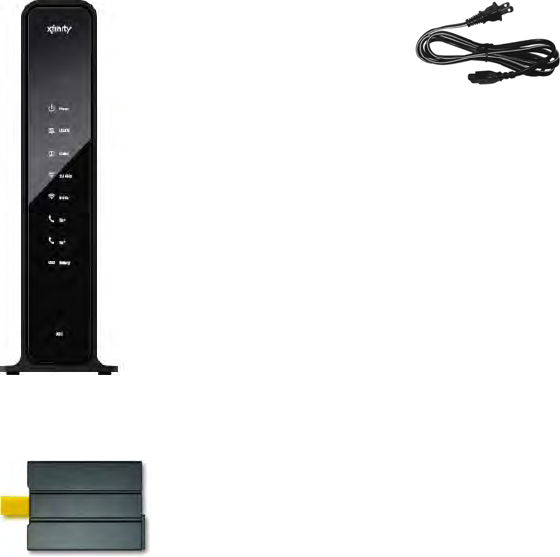
What's In the Carton?
When you receive your residential gateway, you should check the equipment and
accessories to verify that each item is in the carton and that each item is undamaged.
The carton contains the following items:
One DPC3941 DOCSIS Wireless
Residential Voice Gateway
One AC power cord
One Lithium Ion cartridge battery
(May not be provided with all
products.)
If any of these items are missing or damaged, please contact your service provider
for assistance.
Notes:
You need an optional cable signal splitter and additional standard RF coaxial
cables if you want to connect a VCR, a Digital Home Communications Terminal
(DHCT) or a set-top converter, or a TV to the same cable connection as your
residential gateway.
If your product supports telephone service, cables and other equipment needed
for telephone service must be purchased separately. Contact your service
provider to inquire about the equipment and cables you need for telephone
service.
Front Panel Description
OL-29163-01 Rev A 5
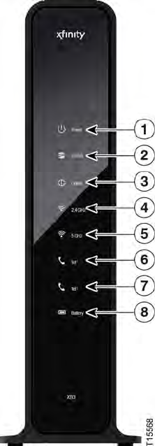
Front Panel Description
The front panel of your residential gateway provides LED status indicators that
indicate how well and at what state your residential gateway is operating. See
Operation of Front Panel Indicators (on page 35), for more information on front
panel LED status indicator functions.
DPC39 (with battery backup capability)
1 POWER—ON, power is applied to the residential gateway
2 US/DS—ON, the residential gateway is exchanging data with the cable network
3 ONLINE—ON, the residential gateway is registered on the network and fully
operational
4 2.4 GHz—ON, the wireless access point is operational. Blinking indicates that
data is being transferred over the wireless connection. OFF indicates that the
wireless access point is not enabled
5 5 GHz—ON, the wireless access point is operational. Blinking indicates that data
is being transferred over the wireless connection. OFF indicates that the wireless
access point is not enabled
6 TEL1—ON indicates telephony service is enabled. Blinks when line 1 is in use.
OFF indicates that phone service for TEL 1 is not enabled
Cha
p
ter 1 Introducin
g
the DOCSIS Wireless Residential Voice Gatewa
y
6 OL-29163-01 Rev
A
7 TEL2—ON indicates telephony service is enabled. Blinks when line 2 is in use.
OFF indicates that phone service for TEL 2 is not enabled.
8 BATTERY (optional model only)—ON indicates that the battery is charged.
Blinking indicates that the battery charge is low. Off indicates that the unit is
operating from battery power, that the battery charge is depleted, or the battery
is defective or missing
Notes:
After the residential gateway is successfully registered on the network, the
POWER, US/DS, and ONLINE LEDs illuminate continuously to indicate that the
residential gateway is active and fully operational.
The high-speed data operation is disabled when operating on battery power;
only the telephone service (if available on this model) is active when operating
on battery power.
LEDs may behave differently when the residential gateway is running on battery
power (without AC power). Most LEDs are disabled if the unit is operating on
battery power. In this mode, the POWER LED blinks to indicate that the unit is
operating under battery power.
The residential gateway should only run on battery power when AC power has
failed. If the POWER LED indicates that the unit is running on battery power,
but the AC power has not failed, verify that the power cord is plugged into a
working AC outlet.

Top Panel Description
OL-29163-01 Rev
A
7
Top Panel Description
Two buttons and LEDs on the top panel of the residential gateway show the status of
the wireless protected setup (WPS) and page features.
1 WPS (WIRELESS PROTECTED SETUP)—OFF (normal condition) wireless
setup is not active. BLINKING indicates the user has activated wireless setup to
add new wireless clients on the wireless network
2 PAGE—OFF (normal condition) indicates the Page feature is not active. SLOW
BLINKING indicates the unit is on and communicating with registered
telephone receivers (handsets). FAST BLINKING indicates that the unit is
transmitting data to registered handsets. To register the unit with a handset,
press the button for 15 seconds. After the unit and handset have registered, press
the button for up to 3 seconds to page registered handsets; press the button again
for up to 3 seconds to stop paging registered handsets.
Cha
p
ter 1 Introducin
g
the DOCSIS Wireless Residential Voice Gatewa
y
8 OL-29163-01 Rev
A
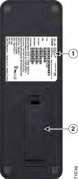
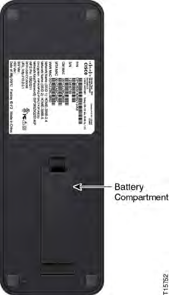
Bottom Panel Description
The bottom panel of your residential gateway contains a product information label
and the door to the battery compartment.
1 LABEL—product information label
2 BATTERY—battery compartment door
Back Panel Description
OL-29163-01 Rev
A
9
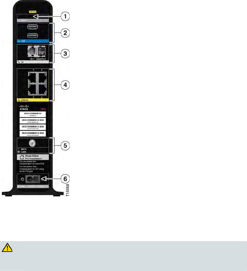
Back Panel Description
The following illustration identifies the back panel components on the Cisco
residential gateway. Descriptions for each component follow the illustration.
Important: Do not connect your PC to both the Ethernet and USB ports at the same
time. Your residential gateway will not function properly if both the Ethernet and
USB ports are connected to your PC at the same time.
Important: Use only the power cord provided with your residential gateway.
CAUTION:
Avoid damage to your equipment. Only use the power cord that is provided
with your residential gateway.

Cha
p
ter 1 Introducin
g
the DOCSIS Wireless Residential Voice Gatewa
y
10 OL-29163-01 Rev
A
1 RESET—A momentary pressing (1-2 seconds) of this switch restarts the device.
Pressing and holding the switch for more than ten seconds first causes a reset-to-
factory-default of all settings and then restarts the device
CAUTION:
The RESET button is for maintenance purposes only. Do not use unless
instructed to do so by your service provider. Doing so may cause you to lose
any settings you have selected.
2 USB (optional for some models)—Connects the residential gateway to selected
devices. For models that support USB, the default is one USB port.
3 TELEPHONE 1 and 2—RJ-11 telephone ports for connecting home telephone
wiring to conventional telephones or fax machines.
4 ETHERNET—Four RJ-45 Ethernet ports to allow connection to the Ethernet port
on your PC or your home network
5 MoCA/Cable—F-connector connects to your home coax network to provide
Cable and MoCA service
6 POWER—Connects the residential gateway to the AC wall outlet

OL-29163-01 Rev
A
11
Introduction
This chapter describes how to properly install the residential gateway
and to connect the residential gateway to a computer and other
devices.
2 Chapter 2
Installing the DOCSIS Wireless
Residential Voice Gateway
In This Chapter
Installation Preparations ...................................................................... 12
Install the Wireless Residential Voice Gateway ............................... 19
Configure Wireless Settings ................................................................ 22
MoCA Installation Guidelines ............................................................ 31
Cha
p
ter 2 Installin
g
the DOCSIS Wireless Residential Voice Gatewa
y
12 OL-29163-01 Rev
A
Installation Preparations
Before installing the residential gateway, make sure that your system meets or
exceeds the requirements listed in this section. Also, make sure that you have
prepared your home and home devices as described in this section.
What Are the System Requirements for Internet Service?
To ensure that your residential gateway operates efficiently for high-speed Internet
service, you must have an Internet-capable PC, Mac, or Internet appliance equipped
with an Ethernet port.
Note: You will also need an active cable input line and an Internet connection.
Minimum Hardware Requirements for a PC
A PC with a Pentium MMX 133 or greater processor recommended
32 MB of RAM
Ethernet port
Minimum Hardware Requirements for a Macintosh
32 MB of RAM
Ethernet port
Minimum Software Requirements for an Ethernet Connection
Operating system with web browser, TCP/IP protocol
What Are the Requirements for Telephone Service?
If you intend to use the residential gateway for digital telephone service, verify that
your home meets or exceeds all of the following requirements.
Maximum Number of Telephones
The RJ-11 telephone-style connectors on the residential gateway can each provide
telephone service to multiple telephones, fax machines, and analog modems.
The maximum number of telephone devices connected to each RJ-11 port is limited
by the total Ringing Load of the telephone devices that are connected. Many
telephone devices are marked with a Ringer Equivalent Number (REN). Each
telephone port on the residential gateway can support up to a 5 REN load.
The sum of the REN load on all of the telephone devices attached to each port must
not exceed 5 REN.
Installation Preparations
OL-29163-01 Rev
A
13
Telephone Device Types
You can use telephone devices that are not labeled with a REN number, but the
maximum number of attached telephone devices cannot be accurately calculated.
With telephone devices that are not labeled, each device should be connected and
the ring signal should be tested before adding more devices. If too many telephone
devices are attached and the ring signal can no longer be heard, telephone devices
should be removed until the ring signal works properly.
Telephones, fax machines, and other telephone devices use the center 2 pins of the
RJ-11 connectors to connect to your primary service.
Dialing Requirements
All your telephones should be set to use Dual-Tone Multi-Frequency (DTMF)
dialing. Pulse dialing may not be supported by your local service provider.
Telephone Wiring Requirements
The residential gateway supports connecting to the interior telephone wiring as well
as connecting directly to a telephone or fax machine. The maximum distance from
the unit to the most distant telephone device must not exceed 1000 feet (300 meters).
Use 26-gauge twisted-pair, or larger, telephone wiring.
Important: Connection to an existing or a new permanently installed home
telephone wiring network should be completed by a qualified installer or at the
direction of your telephone service provider.
What Types of Service Accounts Do I Need?
Depending upon the features your service provider offers, you may need to establish
one or both of the following accounts:
A high-speed Internet access account, if your residential gateway supports an
Internet connection
An account for telephone service, if your residential gateway supports digital
telephone service
Refer to one of the following topics to learn more about the types of service accounts
that you may need to establish.
High-Speed Internet Access Account
If you do not have a high-speed Internet access account, your service provider will
set up your account and become your Internet Service Provider (ISP). Internet access
enables you to send and receive e-mail, access the World Wide Web, and receive
other Internet services.
Cha
p
ter 2 Installin
g
the DOCSIS Wireless Residential Voice Gatewa
y
14 OL-29163-01 Rev
A
You will need to give your service provider information about the residential
gateway in order to use the high-speed internet feature that this product offers. Refer
to Information Your Service Provider Needs (on page 14) to learn how to locate the
information your service provider needs to establish a high-speed Internet access
account for the residential gateway
I Already Have a High-Speed Internet Access Account
If you have an existing high-speed Internet access account, you will need to give
your service provider the serial number and MAC address of the residential gateway
in order to use the high-speed internet feature that this product offers. Refer to
Information Your Service Provider Needs (on page 14) to learn how to locate this
information.
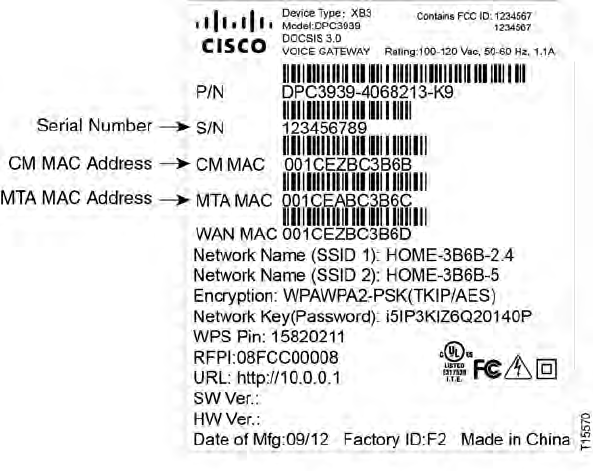
Information Your Service Provider Needs
You will need to give your service provider the following information, which is
printed on the bar code label attached to the device:
The Serial Number (S/N) of the residential gateway. The serial number consists
of a series of nine digits.
The Media Access Control (CM MAC) address of the residential gateway. The
CM MAC address consists of a series of 12 alphanumeric characters.
The Media Access Control (MAC) address of the residential gateway media
terminal adapter (MTA). The MTA MAC address consists of a series of 12
alphanumeric characters.
The following illustration shows a typical bar code label; the image may vary from
the label on the actual product.
DPC3941
FCC ID: VUIDPC3941
Installation Preparations
OL-29163-01 Rev
A
15
Write down these numbers in the spaces provided:
Serial Number _______________________
CM MAC MAC Address ________________________
MTA MAC Address ________________________
Telephone Service
You will need to establish a telephone account with your local service provider to
use your residential gateway for telephone service.
When you contact your service provider, you may be able to transfer your existing
telephone numbers. If not, then your cable telephony service provider will assign a
new telephone number to enable your voice service(s). Discuss these options with
your telephony service provider.
Cha
p
ter 2 Installin
g
the DOCSIS Wireless Residential Voice Gatewa
y
16 OL-29163-01 Rev
A
Where Is the Best Location for My Wireless Residential Voice Gateway?
The ideal location for your residential gateway is where it has access to outlets and
other devices. Think about the layout of your home or office, and consult with your
service provider to select the best location for your residential gateway. Read this
user guide thoroughly before you decide where to place your residential gateway.
Consider these recommendations:
Choose a location close to your computer if you will also use the residential
gateway for high-speed Internet service.
Choose a location that is near an existing RF coaxial connection to eliminate the
need for an additional RF coaxial outlet.
Choose a location that is relatively protected from accidental disturbance or
harm, such as a basement or other protected area.
Choose a location so that there is plenty of room to guide the cables away from
the residential gateway without straining or crimping them.
Choose a location that allows adequate ventilation around the residential
gateway.
Choose a location for the residential gateway that is adjacent to your telephone
equipment if you plan on connecting your phone directly to the residential
gateway.
Note: If you are using the residential gateway to provide service to several
telephones, a professional installer can connect the residential gateway to your
existing home telephone wiring.

Installation Preparations
OL-29163-01 Rev
A
17
Install the Battery
Your residential gateway may include one rechargeable Lithium-Ion battery to
provide stand-by operation in the event of an AC power failure. In the event that
you ever need to replace this battery, contact your service provider.
It is possible to use the residential gateway without the battery. However, if you
choose to operate the residential gateway without a battery, you will not have
telephone service during a power outage.
For information on battery maintenance, refer to Maintaining the Battery (on page
41).
Installing the Battery
Installing the battery requires no tools. Follow these instructions to install the
battery.
WARNING:
Fully charged high-capacity rechargeable batteries should be handled with
care. Replace only with the battery recommended by the manufacturer. Do not
disassemble it or attempt to recharge the battery outside the system. Do not
crush, puncture, dispose of in a fire, short the external contacts, or expose to
high temperature or immerse in water or other liquids. Dispose of the battery
in accordance with local regulations and instructions from your service
provider.
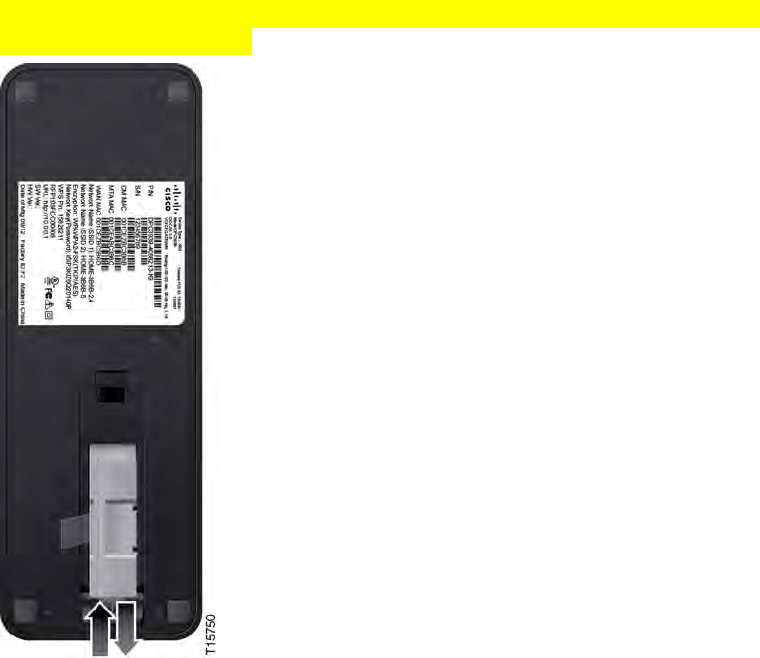
1 Turn the residential gateway so that you are facing the side with the battery
compartment.
2 Gently release the latch to open the battery cover and gain access to the battery
compartment.
Cha
p
ter 2 Installin
g
the DOCSIS Wireless Residential Voice Gatewa
y
18 OL-29163-01 Rev
A
3 Insert the battery into the battery compartment. Do not force the battery into the
compartment, but be sure to press the battery all the way in until it seats fully.
Important: Take care to position the battery correctly. The battery can only be
inserted as shown below.
4 Close the battery compartment door.
Important: After you install the residential gateway and plug it into an AC
electrical outlet as described in Install the Wireless Residential Voice Gateway
(on page 19), it can take as long as 24 hours for the battery to charge fully.
However, you can begin using your high-speed Internet and telephone service
immediately after installation. See Normal Operations (AC Power Applied) (on
page 38) for information on how the LEDs on the front of the residential gateway
indicate the state of the battery charge.
Installation Preparations
OL-29163-01 Rev
A
19
Install the Wireless Residential Voice Gateway
This section describes how to connect your residential gateway to support the
services that the residential gateway offers.
Important: If you have not already done so, insert the battery in the residential
gateway before you install the residential gateway in your home. For assistance
inserting the battery in the residential gateway, go to Install the Battery (on page
17).
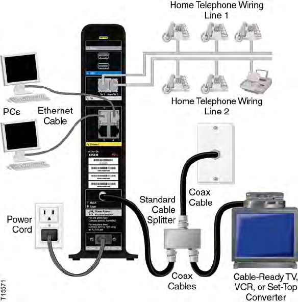
Connect Devices to the Wireless Residential Voice Gateway
Professional installation may be available. Contact your local service provider for
further assistance.
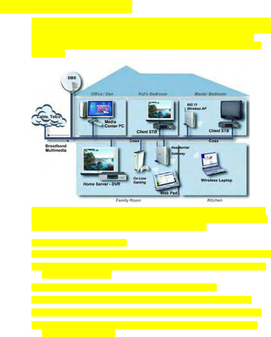
The following diagram illustrates one of the various networking options that are
available to you.

Chapter 2 Installing the DOCSIS Wireless Residential Voice Gateway
20 OL-29163-01 Rev A
Connect the Wireless Residential Voice Gateway
The following installation procedure ensures proper setup and configuration for the
residential gateway.
1 Choose an appropriate and safe location to install the residential gateway (close
to a power source, an active cable connection, your PC-if using high-speed
Internet, and your telephone lines-if using VoIP). For assistance, go to Where Is
the Best Location for My Wireless Residential Voice Gateway? (on page 16).
WARNING:
To prevent possible damage to equipment, disconnect any other telephone
service before connecting your residential gateway to the same wires.
Hazardous electrical voltages can exist on the telephone, Ethernet, or coax
cable wiring. Be sure to disconnect AC power from all devices while
installing your service.
All wiring and connections must be properly insulated to prevent
electrical shock.
Telephone connections to an installed home telephone wiring network
should be done by a qualified installer. The cable telephone service
provider may offer professional installation and connection to the home
telephone wiring network. A fee may be charged for this service.
2 Power off your PC and other networking device; then, unplug them from the
power source.
3 Connect the active RF coaxial cable from your service provider to the coax
connector labeled MoCA/CABLE on the back of the residential gateway.
Note: To connect a TV, DHCT, set-top, or VCR from the same cable connection,
you will need to install a cable signal splitter (not included). Always check with
your service provider before using a splitter as a splitter may degrade the signal.
More information about a MoCA installation, see MoCA Installation Guidelines
(on page 31).
4 Connect your PC to the DPC3941 using one of the following methods:
Ethernet Connection. Connect one end of an Ethernet cable to the Ethernet
port on your PC, and connect the other end to the Ethernet port on the back
of the residential gateway.
Wireless Connection. Make sure that your wireless device is powered up.
You will need to associate your wireless device with the DPC39 once the
DPC39 is operational. Follow the directions provided with your wireless
device for associating with a wireless access point. Make sure that either the
2.4 GHz or the 5 GHz indicator is ON.
For more information about the factory default configuration of the
DPC39, see Configure Wireless Settings (on page 22).
Installation Preparations
OL-29163-01 Rev
A
21
5 If your residential gateway supports digital telephone service (VoIP), connect
one end of a telephone jumper cable (not included) to a telephone outlet in your
home or to a telephone or fax machine. Then connect the other end of the jumper
cable to the appropriate RJ-11 Tel 1 or Tel 2 port on the back of the residential
gateway.
Notes: Telephones that require electrical connectors other than RJ-11 may require
an external adapter (sold separately).
6 Locate the AC power cord provided with your residential gateway. Connect the
barrel connector end of the power cord into the power input on the back of the
residential gateway. Then, plug the other end of the power cord into an AC
outlet.
The residential gateway will perform an automatic search to locate and sign on
to the broadband data network. This process may take up to 2-5 minutes. The
residential gateway will be ready for use when the Power, US/DS, and Online
LEDs on the front panel of the residential gateway stop blinking and remain on
continuously.
7 Plug in and power on your PC and other home network devices. If one or more
of these devices uses wireless networking, the 2.4 GHz or 5 GHz LED on the
residential gateway should be on or blinking.
8 At this point, the installation is complete, and you can begin surfing the Internet.
Note: If your PC does not have Internet access, refer to How Do I Configure
TCP/IP Protocol? (on page 46) for information on how to configure your PC for
TCP/IP. For Internet devices other than PCs, refer to the DHCP or IP Address
configuration section of the User Guide or Operations Manual for those devices.

Cha
p
ter 2 Installin
g
the DOCSIS Wireless Residential Voice Gatewa
y
22 OL-29163-01 Rev
A
Configure Wireless Settings
Setting up the Wireless Residential Gateway for wireless communication provides
you with the freedom to connect to the Internet from any location within range of
the Wireless Access Point (WAP) without having to use wired connections. This
section provides procedures for configuring the WAP to meet your needs. These
options are available as tabs on the Gateway > Connection > WiFi page.
Private WiFi Network - Use this page to choose the wireless network mode that
the Wireless Residential Gateway will use and to set up and other basic features
including Security mode and Network Password.
MAC Filter Settings- Use this page to configure MAC address filtering for your
wireless network separately for 2.4 GHz and 5 GHz networks. <<Are some
words missing here?>>
Add WPS Client - This page allows user to manually set up and connect WPS
clients, WPS PIN method and Push Button. <<Are some words missing here?>>
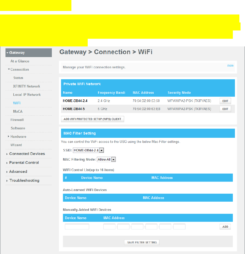
Configure Wireless Settings
OL-29163-01 Rev
A
23
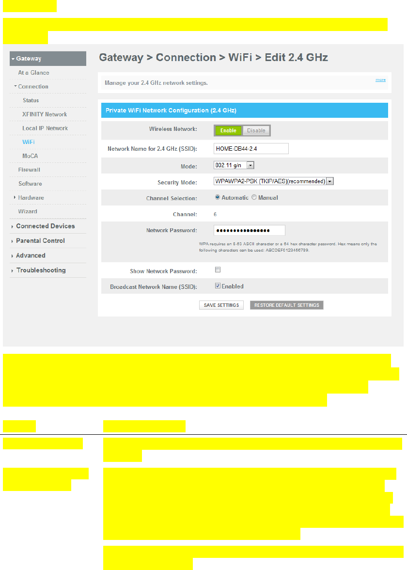
Private WiFi Network
From the Gateway > Connection > WiFi page, click the Edit buttons in 2.4 GHz or
5GHz network to configure Network Name (SSID), Mode, Security Mode. Channel
Selection and Network Password and Enable/Disabling the wireless network or
Broadcasting Network Name.
Cha
p
ter 2 Installin
g
the DOCSIS Wireless Residential Voice Gatewa
y
24 OL-29163-01 Rev
A
Edit 2.4 GHz
This section describes how to configure wireless settings for the 2.4 GHz wireless
network.
Use the descriptions and instructions in the following table to manually configure
the basic settings for wireless communication for the Wireless Residential Gateway.
After you make your selections, click Save Settings to apply your changes or
Restore Default Settings to set values back to factory default values.
Section Field Description
Wireless Network Wireless Network. Use this setting to Enable or Disable the wireless
network.
Network Name for
2.4 GHz (SSID)
The SSID is the name of your wireless network. The SSID is used by
wireless technology to identify your network from other wireless
networks in the area. The SSID can be up to 32 characters long. The
factory default SSID is HOME-XXXX-2.4 where XXXXare the last 4
digits of cable modem MAC address found on the label located on the
bottom of your Wireless Residential Gateway.
This SSID is a unique identity and does not need to be changed unless
you choose to do so.

Configure Wireless Settings
OL-29163-01 Rev
A
25
Section Field Description
Mode Choose one of these options for the network mode:
8.2.11n
802.11 g/n
802.11 b/g/n
Important: When TKIP authentication only is selected, B/G/N Mixed
network mode is not available.
Security Mode Choose one of these options for the security mode
Open (risky)
64 bits (5 Ascii characters or 10 Hex digits)
128 bits (13 Ascii characters or 26 Hex digits)
WPA-PSK(TKIP) (8 to 63 Ascii characters or 64 Hex digits)
WPA-PSK(AES) (8 to 63 Ascii characters or 64 Hex digits)
WPA2-PSK(TKIP) (8 to 63 Ascii characters or 64 Hex digits)
WPA2-PSK(AES) (8 to 63 Ascii characters or 64 Hex digits)
WPA2-PSK(TKIP/AES) (8 to 63 Ascii characters or 64 Hex digits)
WPAWPA2-PSK(TKIP/AES) recommended (8 to 63 Ascii
characters or 64 Hex digits)
Note: Not all wireless adapters support WPA2. WPA is
supported across a wider range of devices. Whether you use
WPA or WPA2, make sure to use a "strong" passphrase. A strong
passphrase is a string of random characters at least 21 characters
in length.
Channel Selection Choose Automatic or Manual.
Automatic. You can select Automatic (factory default) for automatic
channel selection. If Manual is selected, user would be able to select
and set channels.
Channel In Channel Selection, if Manual option is chosen, user can select a
channel from 1 through 11. Only channels 1, 6 and 11 are non-
overlapping channels.
Network Password Depends on Security Mode selected, the Network Password can have
different requirements which are explained in Security Mode. The
factory set password value can be found on the label located on the
bottom of your Wireless Residential Gateway.
To make the Network Password become visible to the user or not.
Every time the page is opened this box is unchecked for the security
reasons.
Cha
p
ter 2 Installin
g
the DOCSIS Wireless Residential Voice Gatewa
y
26 OL-29163-01 Rev
A
Section Field Description
Show Network
Password
When this box is checked (factory default), the gateway transmits or
advertises its presence to other wireless devices. Client devices can
automatically detect the access point when this beacon is enabled
Broadcast Network
Name (SSID)
Leave this box unselected if you want to hide your network from
wireless clients. If you hide your network, you will need to configure
each of your wireless client devices manually.
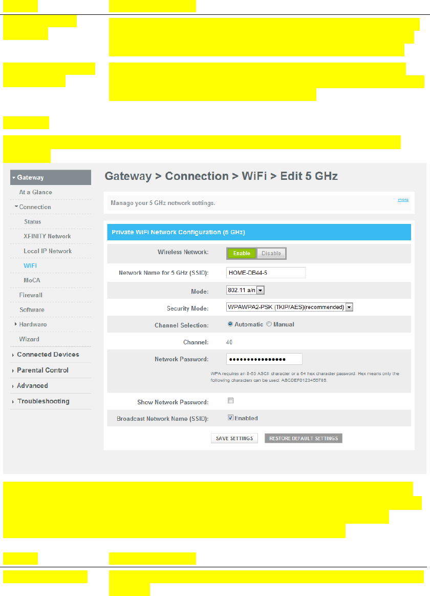
Edit 5GHz
This section describes how to configure wireless settings for the 5 GHz wireless
network.
Use the descriptions and instructions in the following table to manually configure
the basic settings for wireless communication for the Wireless Residential Gateway.
After you make your selections, click Save Settings to apply your changes or
Restore Default Settings to set values back to factory default values.
Section Field Description
Wireless Network
Wireless Network. Use this setting to Enable or Disable the wireless
network.

Configure Wireless Settings
OL-29163-01 Rev
A
27
Section Field Description
Network Name for
5 GHz (SSID)
The SSID is the name of your wireless network. The SSID is used by
wireless technology to identify your network from other wireless
networks in the area. The SSID can be up to 32 characters long. The
factory default SSID is HOME-XXXX-5 where XXXXare the last 4
digits of cable modem MAC address found on the label located on
the bottom of your Wireless Residential Gateway.
This SSID is a unique identity and does not need to be changed
unless you choose to do so.
Mode Choose one of these options for the network mode:
8.2.11n
802.11 a/n
Important: Only the following Security modes will be available:
Open, WPA-PSK (AES) and WPA2-PSK (AES)
Security Mode Choose one of these options for the security mode
Open (risky)
64 bits (5 Ascii characters or 10 Hex digits)
128 bits (13 Ascii characters or 26 Hex digits)
WPA-PSK(TKIP) (8 to 63 Ascii characters or 64 Hex digits)
WPA-PSK(AES) (8 to 63 Ascii characters or 64 Hex digits)
WPA2-PSK(TKIP) (8 to 63 Ascii characters or 64 Hex digits)
WPA2-PSK(AES) (8 to 63 Ascii characters or 64 Hex digits)
WPA2-PSK(TKIP/AES) (8 to 63 Ascii characters or 64 Hex digits)
WPAWPA2-PSK(TKIP/AES) recommended (8 to 63 Ascii
characters or 64 Hex digits)
Note: Not all wireless adapters support WPA2. WPA is
supported across a wider range of devices. Whether you use
WPA or WPA2, make sure to use a "strong" passphrase. A strong
passphrase is a string of random characters at least 21 characters
in length.
Channel Selection Choose Automatic or Manual.
Automatic. You can select Automatic (factory default) for automatic
channel selection. If Manual is selected, user would be able to select
and set channels.
Channel In Channel Selection, if Manual option is chosen, user can select a
channel from 40, 48, 153 and 161.

Cha
p
ter 2 Installin
g
the DOCSIS Wireless Residential Voice Gatewa
y
28 OL-29163-01 Rev
A
Section Field Description
Network Password
Depends on Security Mode selected, the Network Password can have
different requirements which are explained in Security Mode. The
factory set password value can be found on the label located on the
bottom of your Wireless Residential Gateway.
Show Network
Password
To make the Network Password become visible to the user or not.
Every time the page is opened this box is unchecked for the security
reasons.
Broadcast Network
Name (SSID)
When this box is checked (factory default), the gateway transmits or
advertises its presence to other wireless devices. Client devices can
automatically detect the access point when this beacon is enabled.
Leave this box unselected if you want to hide your network from
wireless clients. If you hide your network, you will need to configure
each of your wireless client devices manually.
Configure Wireless Settings
OL-29163-01 Rev
A
29
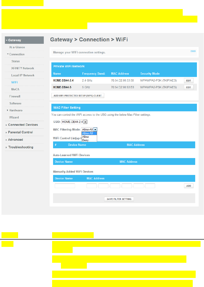
MAC Filter Settings
Use this page to configure MAC address filtering for your wireless network
separately for 2.4GHz and 5GHz networks. This feature allows user to give access
privileges to certain wireless clients.
Section Field Description
SSID
Use this section to select which SSID would like to apply the filtered
clients to.
Allow All- allow access to all the clients included in WiFi
Control List
Allow- allow access to the selected clients in WiFi Control List
Deny- deny access to the selected clients in WiFi Control List
Cha
p
ter 2 Installin
g
the DOCSIS Wireless Residential Voice Gatewa
y
30 OL-29163-01 Rev
A
Section Field Description
Manually Added
WiFi Devices
This section allows the user to add WiFi client into the WiFi Control
List. Enter the MAC address of the device and select a name for it
and click “ADD.”
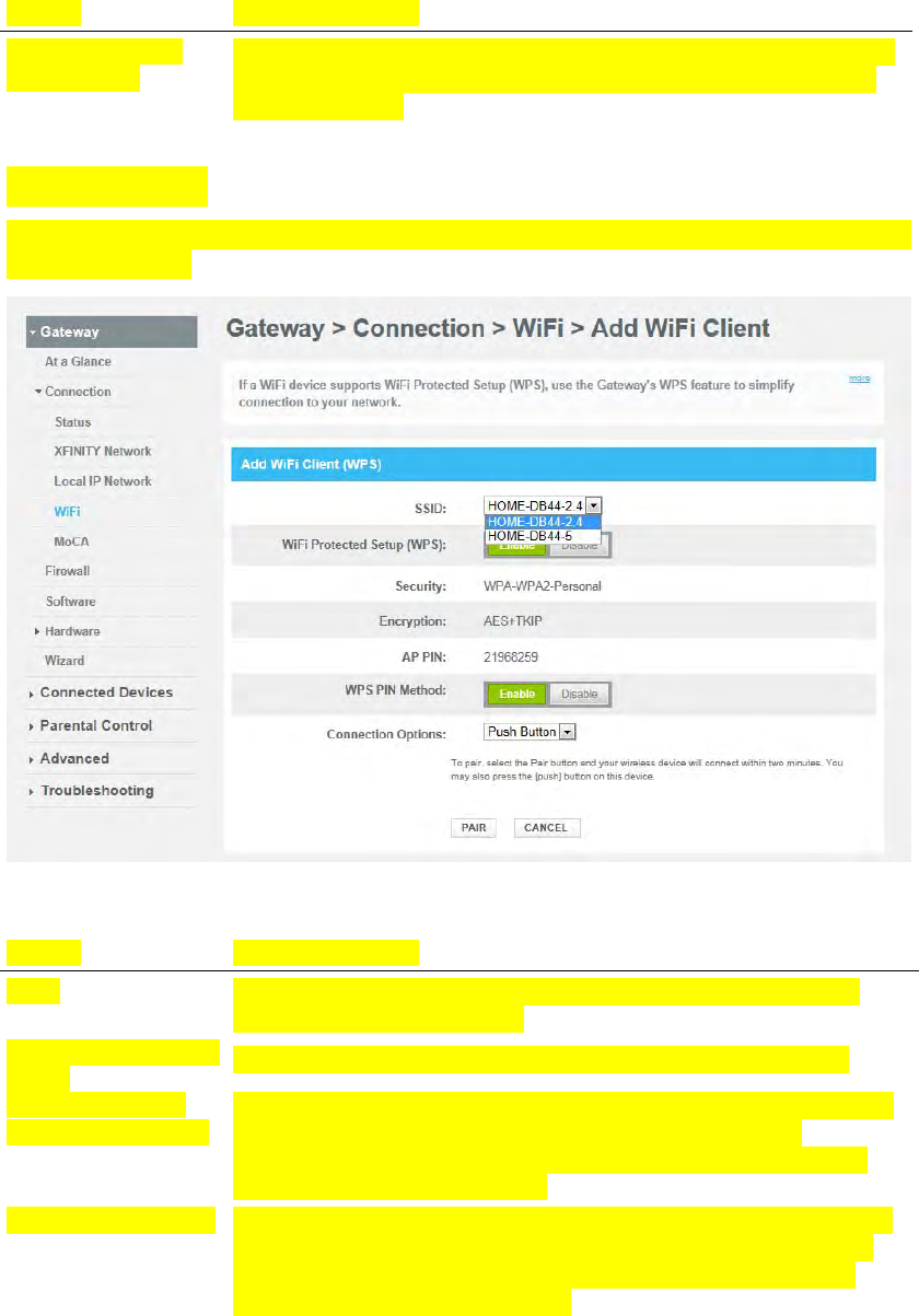
Add WPS Client
This page allows user to manually set up and connect WPS clients, WPS PIN method
and Push Button.
Section Field Description
SSID
Use this section to select which SSID would like to be selected to
connect a client to using WPS.
WiFi Protected Setup
(WPS) This section allows the user to enable/disable WPS mechanism.
WPS PIN Method This section allows the user to enable/disable the WPS PIN Method.
Connection Options
User can select to use Push Button method or PIN Method
connection. In PUSH Button mode, click PAIR after the client has
asked WPS button to be pushed.
Wireless Clients PIN To pair, select the Pair button and your wireless device will connect
within two minutes. You may also press the [push] button on this
device. The Wireless Clients PIN, found from client, needs to be
entered in this field and click PAIR
MoCA Installation Guidelines
OL-29163-01 Rev
A
31
MoCA Installation Guidelines
MoCA is an in-home distribution technology that leverages the coax cable networks
that exist in more than 90% of US households. MoCA is an attractive option because
it provides a relatively low-cost method of getting DVR and other multimedia
sharing video services to multiple TVs within the home without additional cable
installation.
MoCA operates over the physical layer of the home coaxial cable plant in the 1000-
1500MHz spectrum. Its infrastructure begins at the service provider’s drop cable at
the first passive splitter connected to the home coax network.
Recommended Installation Guidelines
The following guidelines are recommended for a home network prior to installation.
The maximum cable distance supported between the network coordinator and
the last outlet is 300 feet.
The maximum attenuation permitted between nodes is 25 dB.
Branches within the home-network should flow from secondary splitters.
Assess the home network and determine the data rates between coax outlets.
Sectionalize the individual MoCA nodes to validate proper operation of the
device’s MoCA interface.
Cha
p
ter 2 Installin
g
the DOCSIS Wireless Residential Voice Gatewa
y
32 OL-29163-01 Rev
A
Evaluate and certify the integrity of the coax cable plant between MoCA nodes.
Identify sources of noise and interference on the MoCA spectrum.
Re-qualify additional coax outlets to support MoCA-enabled devices and
services.
Pre-Installation Procedure
Prior to installing MoCA, complete the following tasks:
1 Contact your service provider and ensure that the wireless residential gateway is
enabled for MoCA services.
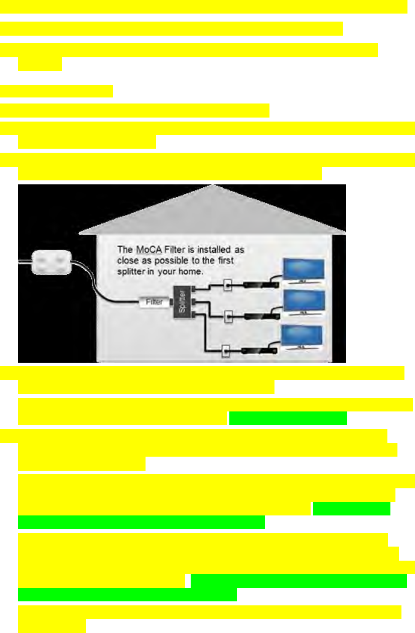
2 Ensure that a MoCA filter has been has been installed by your service provider at
the home’s entry point, as shown in the following illustration:
3 Log-in to your residential gateway’s user interface from any browser using the
login/password provided by your service provider.
4 From the menu options in the user interface go to Gateway/Connections/MoCA
and ensure that the MoCA is set to enable. <<Is this path correct?>>
5 If you have not already done so, connect the coaxial cable from a wall cable
outlet within the home network to the MoCA/Cable port on the rear panel of
your residential gateway.
6 If you have not already done so, connect the existing coaxial cable from your TV,
set-top-box (or any other device that was previously connected to the coaxial
cable outlet) to the TV OUT port on the residential gateway. <<Remove this
step? There is no TV OUT port on the DPC3939.>>
7 Turn on your TV or the device you had connected to the TV-OUT Port, and
confirm that Cable service is available. If TV service is not available verify the
coaxial cables in the residential gateway are securely connected to the right ports
as described in the previous steps. <<Remove this step per the following note?
There is no TV OUT port on the DPC3939.>>
Note: Disregard this step if you are not using the MoCA residential gateway’s
TV OUT port.

MoCA Installation Guidelines
OL-29163-01 Rev
A
33
8 If you have not already done so, AC power cord provided with your residential
gateway. Connect the barrel connector end of the power cord into the power
input on the back of the residential gateway. Then, plug the other end of the
power cord into an AC outlet.
The residential gateway will perform an automatic search to locate and sign on
to the broadband data network. This process may take up to 2-5 minutes. The
residential gateway will be ready for use when the Power, US/DS, and Online
LEDs on the front panel of the residential gateway stop blinking and remain on
continuously. <<Please verify this step is correct.>>
9 Wait a few seconds for the device to de discovered. When discovered an LED
labeled 2.4 GHz or 5 GHz. should turn on. At this point a MoCA node should be
active in the network. <<Please verify this step is correct.>>
10 If you have not already done so, connect an Ethernet compatible device (for
example, a set-top, , computer, or PlayStation) to the residential gateway’s
Ethernet port. The ONLINE LED should turn on and the device should be ready
to use. <<Please verify this step is correct.>>
11 Follow the steps above to connect additional residential gateways to the
network; note that up 15 residential gateways can be added to a MoCA
network.<<Please verify this step is correct.>>
12 From the user interface, you can monitor a limited number of parameters
associated with the MoCA network. You may login at any time to check for
status or for troubleshooting purposes. <<Please verify this step is correct.>>

OL-29163-01 Rev A 34
Introduction
This section describes the behavior of the front panel indicators when
the residential gateway is first powered up, during normal operations,
and in special conditions.
3 Chapter 3
Operation of Front Panel
Indicators
In This Chapter
Initial Power Up, Calibration, and Registration (AC Power
applied) .................................................................................................. 36
Normal Operations (AC Power Applied) ......................................... 38
Special Conditions ................................................................................ 39

Chapter 3 Operation of Front Panel Indicators
35 OL-29163-01 Rev A
Initial Power Up, Calibration, and Registration (AC
Power applied)
The following chart illustrates the sequence of steps and the corresponding
appearance of the residential gateway front panel LED status indicators during
power up, calibration, and registration on the network when AC power is applied to
the residential gateway. Use this chart to troubleshoot the power up, calibration, and
registration process of your residential gateway.
Note: After the residential gateway completes Step 7 (Data Network Registration
Complete), the residential gateway proceeds immediately to Normal Operations. See
Normal Operations (AC Power applied) (on page 38).
Front Panel LED Status Indicators During Initial Power Up, Calibration, and
Registration
Part 1, High Speed Data Registration
Step: 1 2 3 4 5 6
Front Panel
Indicator
Self
Test
Downstream
Scan
Downstream
Signal Lock
Ranging Requesting IP
Address
Request High
Speed Data
Provisioning File
1 POWER On On On On On On
2 US/DS On Blinking On On On On
3 ONLINE On Off Off Off Off Blinking
4 2.4 GHz On On or Blinking On or Blinking On or
Blinking
On or Blinking On or Blinking
5 5G Hz On On or Blinking On or Blinking On or
Blinking
On or Blinking On or Blinking
6 TEL1 On Off Off Off Off Off
7 TEL2 On Off Off Off Off Off
8 BATTERY On – When battery is charged
Blinks – When battery charge is low
Off – When there is no battery in the unit

Initial Power Up, Calibration, and Registration (AC Power applied)
OL-29163-01 Rev A 36
Front Panel LED Status Indicators During Initial Power Up, Calibration, and
Registration
Part 2, Telephone Registration
Step: 7 8 9 10 11
Front Panel
Indicator
Data Network
Registration
Complete
Requesting
Telephone IP
Address
Request
Telephone
Provisioning File
Restarting Voice
Service
Telephone
Registration
Complete
1 POWER On On On On On
2 US/DS On On On On On
3 ONLINE On On On On On
4 2.4 GHz On or
Blinking
On or Blinking On or Blinking On or Blinking On or Blinking
5 5 GHz On or
Blinking
On or Blinking On or Blinking On or Blinking On or Blinking
6 TEL1 Off Blinking Off Blinking On
7 TEL2 Off Off Blinking Blinking On
8 BATTERY On – When battery is charged
Blinks – When battery charge is low
Off – When there is no battery in the unit

Chapter 3 Operation of Front Panel Indicators
37 OL-29163-01 Rev A
Normal Operations (AC Power Applied)
The following chart illustrates the appearance of the residential gateway front panel
LED status indicators during normal operations when AC power is applied to the
gateway.
Front Panel LED Status Indicators During Normal Conditions
Front Panel Indicator Normal Operations
1 POWER On
2 US/DS On
3 ONLINE On
4 2.4 GHz On - When the wireless access point is enabled and
operational
Blinks - When data is being transferred between the
customer premise equipment (CPE) and the wireless
home gateway
Off - When the wireless access point is disabled by the
user
5 5 GHz On - When the wireless access point is enabled and
operational
Blinks - When data is being transferred between the CPE
and the wireless home gateway
Off - When the wireless access point is disabled by the
user
6 TEL1 On - When telephony service is enabled
Blinks - When line 1 is in use
7 TEL2 On - When telephony service is enabled
Blinks - When line 2 is in use
8 BATTERY On – When battery is charged
Blinks – When battery charge is low
Off – When there is no battery in the unit

Special Conditions
OL-29163-01 Rev A 38
Special Conditions
The following chart describes the appearance of the residential gateway front panel
LED status indicators during special conditions to show when you have been denied
network access.
Front Panel LED Status Indicators During Special Conditions
Front Panel Indicator Network Access Denied
1 POWER Slow Blinking
(once per second)
2 US/DS Slow Blinking
(once per second)
3 ONLINE Slow Blinking
(once per second)
4 2.4 GHz Slow Blinking
(once per second)
5 5 GHz Slow Blinking
(once per second)
6 TEL1 Off
7 TEL2 Off
8 BATTERY On

OL-29163-01 Rev A 439
Introduction
This chapter describes how to maintain and replace the battery that is
included with the residential gateway.
4 Chapter 4
Maintaining the Battery
In This Chapter
Location of the Battery ......................................................................... 42
Battery Maintenance ............................................................................. 43
Chapter 4 Maintaining the Battery
40 OL-29163-01 Rev A
Location of the Battery
The following illustration shows the location of the battery.

Battery Maintenance
OL-29163-01 Rev A 41
Battery Maintenance
If your residential gateway contains a battery backup feature, a high-capacity
rechargeable battery provides stand-by operation in the event of an AC power
failure. You can replace the battery without the use of any tools.
WARNING:
Fully charged high-capacity rechargeable batteries should be handled with
care. Replace only with the battery recommended by the manufacturer. Do not
disassemble it or attempt to recharge the battery outside the system. Do not
crush, puncture, dispose of in a fire, short the external contacts, or expose to
high temperature or immerse in water or other liquids. Dispose of the battery
in accordance with local regulations and instructions from your service
provider.
Charging the Battery
The battery begins to charge automatically as soon as you attach the residential
gateway to the AC electrical outlet. When you first plug in the residential gateway,
the POWER LED status indicator illuminates.
Important: It may take as long as 24 hours for the battery to charge fully.
Removing and Replacing the Battery
Under normal circumstances, the battery should last for several years. The
BATTERY LED status indicator blinks to indicate that the battery should be
replaced soon. Contact your service provider to obtain replacement batteries and for
disposal instructions.
Follow these steps to remove and replace the battery. You can remove and replace
the battery without disconnecting the AC power source.
1 Turn the residential gateway so that you are facing the side with the battery
compartment.
2 Gently release the latch to open the battery cover and gain access to the battery
compartment.
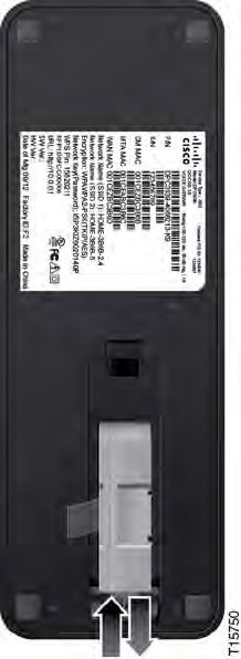
3 Grasp the plastic strip on the front of the battery and gently slide the battery
forward to remove it from the battery compartment.
Chapter 4 Maintaining the Battery
42 OL-29163-01 Rev A
4 Insert a new battery into the battery compartment. Do not force the battery into
the compartment, but be sure to press the battery all the way in until it seats
fully.
5 Close the battery compartment door. The battery lock will automatically re-
engage.
Important: It can take as long as 24 hours for the battery to charge fully.
Note: Dispose of the battery in accordance with local regulations and
instructions from your service provider.
Using the Wireless Residential Voice Gateway Without a Battery
If you want, you can use the residential gateway without a battery. If you need to
remove the battery, follow the procedures found in Removing and Replacing the
Battery (on page 43).
Important: If you choose to operate your residential gateway without a battery, you
risk losing your telephone service during a power outage.

OL-29163-01 Rev A 43
Introduction
This chapter describes the most common issues that may occur after
the residential gateway is installed and provides possible solutions
and tips for improved performance of the residential gateway.
5 Chapter 5
Troubleshooting the DOCSIS
Wireless Residential Voice
Gateway
In This Chapter
Frequently Asked Questions ............................................................... 46
Common Troubleshooting Issues ....................................................... 52
Tips for Improved Performance ......................................................... 54
Chapter 5 Troubleshooting the DOCSIS Wireless Residential Voice Gateway
44 OL-29163-01 Rev A
Frequently Asked Questions
This section provides answers to common questions about the residential gateway.
How Do I Configure TCP/IP Protocol?
To configure TCP/IP protocol, you need to have an Ethernet Network Interface Card
(NIC) with TCP/IP communications protocol installed on your system. TCP/IP is a
communications protocol used to access the Internet. This section contains
instructions for configuring TCP/IP on your Internet devices to operate with the
residential gateway in Microsoft Windows or Macintosh environments.
TCP/IP protocol in a Microsoft Windows environment is different for each
operating system. Follow the appropriate instructions in this section for your
operating system.
Configuring TCP/IP on Windows 7 Systems
1 Open Network Connections by clicking the Start button, and then clicking
Control Panel.
2 In the Search box, type adapter, and then, under Network and Sharing Center,
click View network connections.
3 Right-click the connection that you want to change, and then click Properties. If
you are prompted for an administrator password or confirmation, type the
password or provide confirmation. The Local Area Connection Properties
window opens.
4 Click the Networking tab.
5 Under This connection uses the following items, click either Internet Protocol
Version 4 (TCP/IPv4) or Internet Protocol Version 6 (TCP/IPv6), and then click
Properties.
6 To specify IPv4 IP address settings, do one of the following:
To get IP settings automatically using DHCP, click Obtain an IP address
automatically, and then click OK.
To specify an IP address, click Use the following IP address, and then, in the
IP address, Subnet mask, and Default gateway boxes, type the IP address
settings.
7 To specify IPv6 IP address settings, do one of the following:
To get IP settings automatically using DHCP, click Obtain an IPv6 address
automatically, and then click OK.
To specify an IP address, click Use the following IPv6 address, and then, in
the IPv6 address, Subnet prefix length, and the Default gateway boxes, type
the IP address settings.
Frequently Asked Questions
OL-29163-01 Rev A 45
8 To specify DNS server address settings, do one of the following:
To get a DNS server address automatically using DHCP, click Obtain DNS
server address automatically, and then click OK.
To specify a DNS server address, click Use the following DNS server
addresses, and then, in the Preferred DNS server and Alternate DNS server
boxes, type the addresses of the primary and secondary DNS servers.
9 To change advanced DNS, WINS, and IP settings, click Advanced.
10 When you are finished, click OK.
11 Try to access the Internet. If you cannot access the Internet, contact your service
provider for further assistance.
Configuring TCP/IP on Windows XP Systems
1 Click Start, and depending on your Start menu setup, choose one of the
following options:
If you are using the Windows XP Default Start Menu, select Connect to,
choose Show all connections, and then go to step 2.
If you are using the Windows XP Classic Start Menu, select Settings, choose
Network Connections, click Local Area Connection, and then go to step 3.
2 Double-click the Local Area Connection icon in the LAN or High-Speed Internet
section of the Network Connections window.
3 Click Properties in the Local Area Connection Status window.
4 Click Internet Protocol (TCP/IP), and then click Properties in the Local Area
Connection Properties window.
5 Select both Obtain an IP address automatically and Obtain DNS server address
automatically in the Internet Protocol (TCP/IP) Properties window, and then
click OK.
6 Click Yes to restart your computer when the Local Network window opens. The
computer restarts. The TCP/IP protocol is now configured on your PC, and your
Ethernet devices are ready for use.
7 Try to access the Internet. If you cannot access the Internet, contact your service
provider for further assistance.
Configuring TCP/IP on Macintosh Systems
1 Click the Apple icon in the upper-left corner of the Finder. Scroll down to
Control Panels, and then click TCP/IP.
2 Click Edit on the Finder at the top of the screen. Scroll down to the bottom of the
menu, and then click User Mode.
3 Click Advanced in the User Mode window, and then click OK.
4 Click the Up/Down selector arrows located to the right of the Connect Via
section of the TCP/IP window, and then click Using DHCP Server.
Chapter 5 Troubleshooting the DOCSIS Wireless Residential Voice Gateway
46 OL-29163-01 Rev A
5 Click Options in the TCP/IP window, and then click Active in the TCP/IP
Options window.
Note: Make sure that the Load only when needed option is unchecked.
6 Verify that the Use 802.3 option located in the upper-right corner of the TCP/IP
window is unchecked. If there is a check mark in the option, uncheck the option,
and then click Info in the lower-left corner.
7 Is there a Hardware Address listed in this window?
If yes, click OK. To close the TCP/IP Control Panel window, click File, and
then scroll down to click Close. You have completed this procedure.
If no, you must power off your Macintosh.
8 With the power off, simultaneously press and hold down the Command
(Apple), Option, P, and R keys on your keyboard. Keeping those keys pressed
down, power on your Macintosh but do not release these keys until you hear the
Apple chime at least three times, then release the keys and let the computer
restart.
9 When your computer fully reboots, repeat steps 1 through 7 to verify that all
TCP/IP settings are correct. If your computer still does not have a Hardware
Address, contact your authorized Apple dealer or Apple technical support center
for further assistance.
How Do I Renew the IP Address on My PC?
If your PC cannot access the Internet after the residential gateway is online, it is
possible that your PC did not renew its IP address. Follow the appropriate
instructions in this section for your operating system to renew the IP address on
your PC.
Renewing the IP Address on Windows 7 Systems
1 Click the Windows Start button.
2 Type cmd in the Search box. The cmd window opens.
3 Type ipconfig /renew and press Enter to renew the IP address of the computer.
Renewing the IP Address on Windows XP Systems
1 Click Start, and then click Run. The Run window opens.
2 Type cmd in the Open field and click OK. A window with a command prompt
opens.
3 Type ipconfig /release at the C:/ prompt and press Enter. The system releases
the IP address.
4 Type ipconfig /renew at the C:/ prompt and press Enter. The system displays a
new IP address.
Frequently Asked Questions
OL-29163-01 Rev A 47
5 Click the X in the upper-right corner of the window to close the Command
Prompt window. You have completed this procedure.
Note: If you cannot access the Internet, contact your service provider for further
assistance.
Renewing the IP Address on Windows 95, 98, 98SE, and ME Systems
6 Click Start, and then click Run. The Run window opens.
7 In the Open field, type winipcfg and click OK. The IP Configuration window
opens.
8 Click the down arrow to the right of the top field, and select the Ethernet adapter
that is installed on your PC. The IP Configuration window displays the Ethernet
adapter information.
9 Click Release, and then click Renew. The IP Configuration window displays a
new IP address.
10 Click OK to close the IP Configuration window and complete this procedure.
Note: If you cannot access the Internet, contact your service provider for further
assistance.
Renewing the IP Address on Macintosh Systems
1 Close all open programs.
2 Open your Preferences folder.
3 Drag the tcp/ip preferences file to the Trash.
4 Close all open windows and empty the Trash.
5 Restart your computer.
6 As your computer starts, simultaneously press and hold down the Command
(Apple), Option, P, and R keys on your keyboard. Keeping those keys pressed
down, power on your Macintosh but do not release these keys until you hear the
Apple chime at least three times; then, release the keys and let the computer
restart.
7 When your computer fully reboots, click the Apple icon in the upper-left corner
of the Finder. Scroll down to Control Panels, and then click TCP/IP.
8 Click Edit on the Finder at the top of the screen. Scroll down to the bottom of the
menu, and then click User Mode.
9 Click Advanced in the User Mode window, and then click OK.
10 Click the Up/Down selector arrows located to the right of the Connect Via
section of the TCP/IP window, and then click Using DHCP Server.
Chapter 5 Troubleshooting the DOCSIS Wireless Residential Voice Gateway
48 OL-29163-01 Rev A
11 Click Options in the TCP/IP window, and then click Active in the TCP/IP
Options window.
Note: In some cases, the Load only when needed option does not appear. If it
appears, select the option. A check mark appears in the option.
12 Verify that the Use 802.3 option located in the upper-right corner of the TCP/IP
window is not selected. If there is a check mark in the option, select the option to
clear the check mark, and then click Info in the lower-left corner.
13 Is there a Hardware Address listed in this window?
If yes, click OK. To close the TCP/IP Control Panel window, click File, and
then scroll down to click Close.
If no, repeat these instructions from step 6.
14 Reboot your computer.
What if I Don't Subscribe to Cable TV?
If cable TV is available in your area, data service may be made available with or
without subscribing to cable TV service. Contact your local service provider for
complete information on cable services, including high-speed Internet access.
How Do I Arrange for Installation?
Call your service provider to inquire about professional installation. A professional
installation ensures proper cable connection to the residential gateway and to your
PC, and it ensures the proper configuration of all hardware and software settings.
Contact your service provider for more information about installation.
How Does the Wireless Residential Voice Gateway Connect to My Computer?
The residential gateway connects to the 10/100/1000BASE-T Ethernet port on your
PC. To use the Ethernet interface, Ethernet cards available from your local PC or
office supply retailer, or from your service provider. For best performance over an
Ethernet connection, your PC should be equipped with a Gigabit Ethernet card.
Frequently Asked Questions
OL-29163-01 Rev A 49
After My Wireless Residential Voice Gateway Is Connected, How Do I Access the
Internet?
Your local service provider becomes your Internet Service Provider (ISP). They offer
a wide range of services including e-mail, chat, news, and information services. Your
service provider will provide the software you will need.
Can I Watch TV and Surf the Internet at the Same Time?
Absolutely! If you subscribe to cable television service, you can watch TV and use
your residential gateway at the same time by connecting your TV and your
residential gateway to the cable network using an optional cable signal splitter.
Can I Use my Existing Phone Number with the Wireless Residential Voice
Gateway?
Telephone numbers are portable in some areas. Contact your telephone service
provider for more information about using an existing telephone number.
How Many Telephones Can I Connect?
The RJ-11 telephone-style connectors on the residential gateway can each provide
telephone service to multiple telephones, fax machines, and analog modems. The
maximum number of telephone devices connected to each RJ-11 port is limited by
the total Ringing Load of the telephone devices that are connected. Many telephone
devices are marked with a Ringer Equivalent Number (REN). Each telephone port
on the residential gateway can support up to a 5 REN load. The sum of the REN load
on all of the telephone devices attached to each port must not exceed 5 REN.
Chapter 5 Troubleshooting the DOCSIS Wireless Residential Voice Gateway
50 OL-29163-01 Rev A
Common Troubleshooting Issues
This section describes common problems and offers solutions.
I don't understand the front panel status indicators
See Operation of Front Panel Indicators (on page 35), for more detailed information
on front panel LED status indicator operation and function.
The Wireless Residential Voice Gateway does not register an Ethernet
connection
Try one of the following solutions:
Verify that your computer has an Ethernet card and that the Ethernet driver
software is properly installed. If you purchase and install an Ethernet card,
follow the installation instructions very carefully.
Verify the status of the front panel status indicator lights.
The Wireless Residential Voice Gateway does not register an Ethernet
connection after connecting to a hub
If you are connecting multiple PCs to the residential gateway, you should first
connect the residential gateway to the uplink port of the hub using the correct
crossover cable. The LINK LED of the hub will illuminate continuously.
The Wireless Residential Voice Gateway does not register a cable connection
The residential gateway works with a standard, 75-ohm, RF coaxial cable. If you are
using a different cable, your residential gateway will not function properly. Contact
your service provider to determine whether you are using the correct cable.
There is no dial tone when I lift the handset
Try the following solutions if you cannot hear a dial tone:
Your telephone wiring may be connected to the wrong RJ-11 port on the
residential gateway. The residential gateway has two telephone ports. Verify that
you are connected to the correct telephone port.
There may be a problem with your telephone set. Use a different telephone set
and listen to hear dial tone.
Common Troubleshooting Issues
OL-29163-01 Rev A 51
There may be a problem with your home telephone wiring. Use a telephone and
connect directly to the same RJ-11 port on the back of the unit. If the dial tone is
working here but does not work at other locations in the home, a professional
may need to diagnose and repair a problem with your telephone wiring.
Verify that the telephone company has removed the previous telephone service
from your home telephone wiring.
Your telephone service may not be enabled from your cable telephony service
provider. Contact your cable telephony service provider for more information.

Chapter 5 Troubleshooting the DOCSIS Wireless Residential Voice Gateway
52 OL-29163-01 Rev A
Tips for Improved Performance
If your residential gateway does not perform as expected, the following tips may
help. If you need further assistance, contact your service provider.
Verify that the plug to your residential gateway AC power is properly inserted
into an electrical outlet.
Verify that your residential gateway AC power cord is not plugged into an
electrical outlet that is controlled by a wall switch. If a wall switch controls the
electrical outlet, make sure the switch is in the ON position.
Verify that the ONLINE LED status indicator on the front panel of your
residential gateway is illuminated.
Verify that your cable service is active and that it supports two-way service.
Verify that all cables are properly connected, and that you are using the correct
cables.
If you are using the Ethernet connection, verify that TCP/IP settings are properly
configured.
Verify that you have called your service provider and given them the serial
number and MAC address of your residential gateway.
If you are using a cable signal splitter so that you can connect the residential
gateway to other devices, remove the splitter and reconnect the cables so that the
residential gateway is connected directly to the cable input. If the residential
gateway now functions properly, the cable signal splitter may be defective and
may need to be replaced.
If you are connected to your PC with an Ethernet connection, your PC should be
equipped with a Gigabit Ethernet card for best performance.

OL-29163-01 Rev A 53
If You Have Questions
If you have technical questions, call Cisco Services for assistance.
Follow the menu options to speak with a service engineer.
Access your company's extranet site to view or order additional
technical publications. For accessing instructions, contact the
representative who handles your account. Check your extranet site
often as the information is updated frequently.
6 Chapter 6
Customer Information

Cisco Systems, Inc.
5030 Sugarloaf Parkway, Box 465447
Lawrenceville, GA 30042
678 277-1120
800 553-6387
www.cisco.com
This document includes various trademarks of Cisco Systems, Inc. Please see the Notices
section of this document for a list of the Cisco Systems, Inc. trademarks used in this
document.
Product and service availability are subject to change without notice.
© 2013 Cisco and/or its affiliates. All rights reserved.
March 2013 Printed in United States of America
Part Number 78-4041469-01 Rev A