PEGATRON IPV5K6KUSHPNA Bluetooth Set-Top Box User Manual Cisco IPV5K IPV6K Set Tops Installation Guide
PEGATRON CORPORATION Bluetooth Set-Top Box Cisco IPV5K IPV6K Set Tops Installation Guide
UserManual.wiki
>
PEGATRON
>
IPV5K6KUSHPNA User Manual
user manual
Navigation menu
Upload a User Manual
Namespaces
Wiki Guide
HTML
PDF
Info
Views
User Manual
Discussion / Help
Navigation
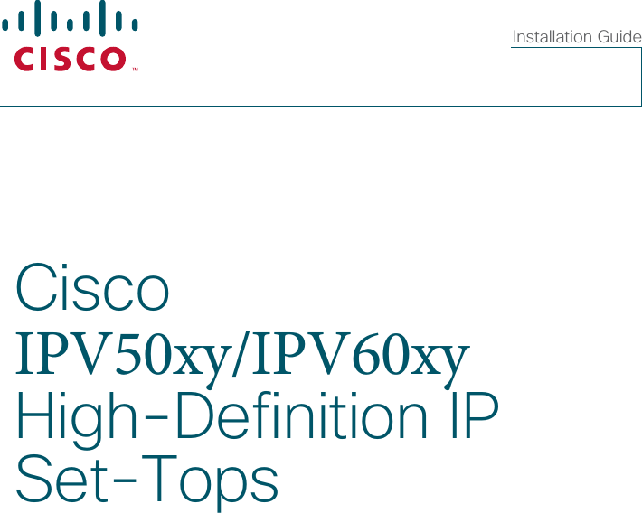

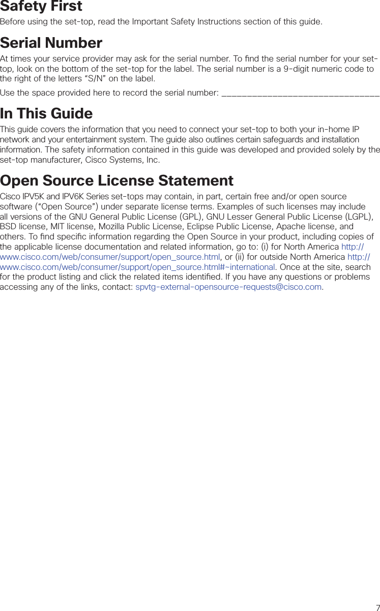
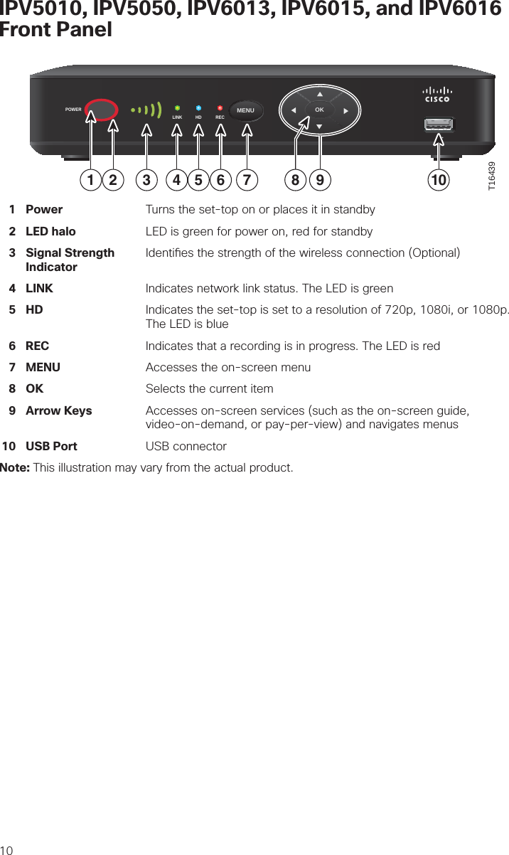

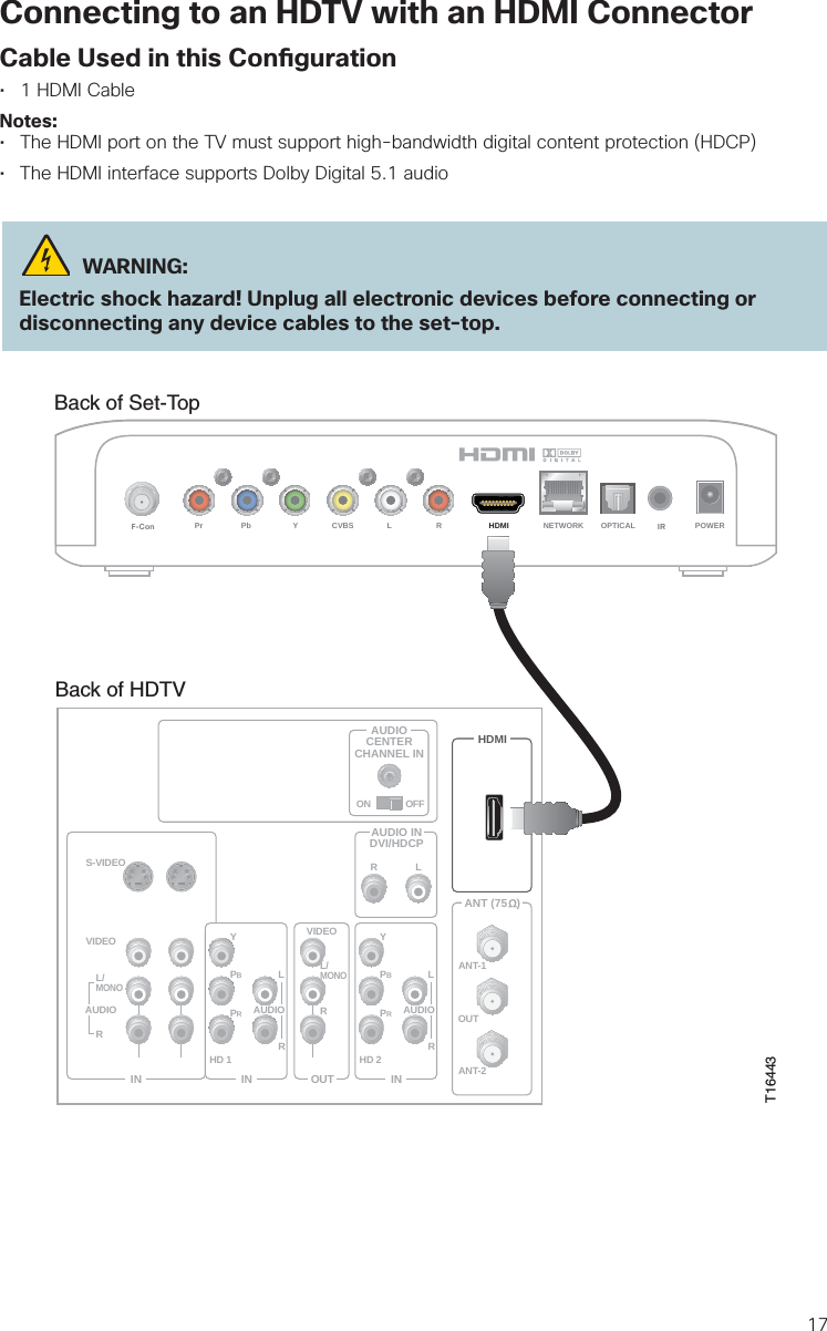
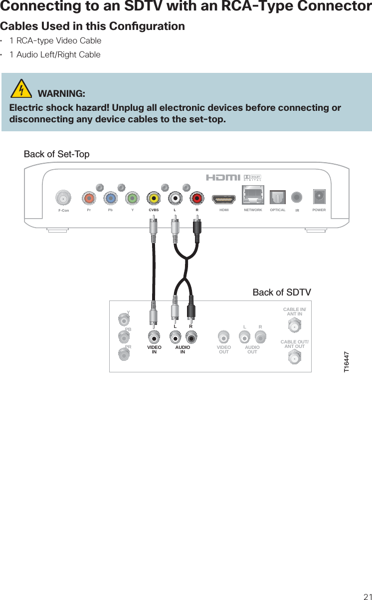
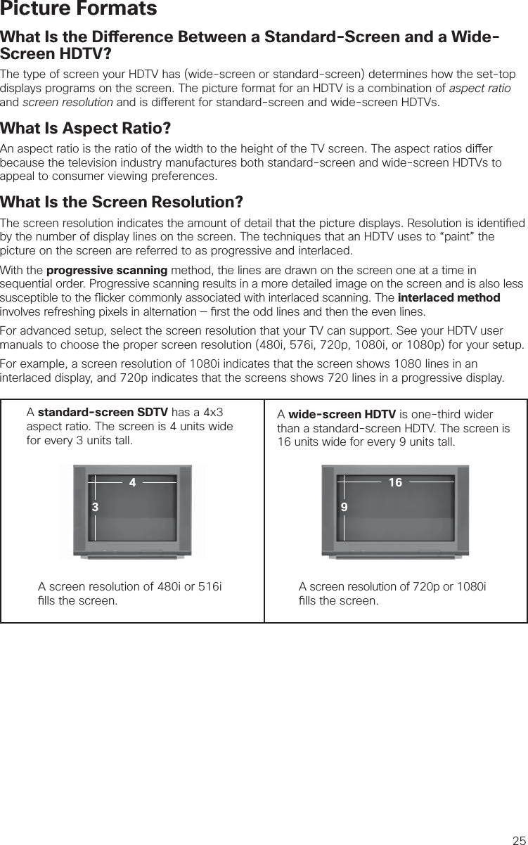
![18Connecting to an HDTV with a DVI ConnectorCables Used in this Con guration• 1 HDMI-to-DVI Cable or 1 HDMI Cable and 1 HDMI-to-DVI Adapter• 1 Audio Left/Right Cable (You can also use an optical cable [indicated by the dotted line] insteadof the Audio Left/Right Cable as shown in the diagram, dependent upon your TV’s capabilities.)Notes:• The DVI port on the TV must support high-bandwidth digital content protection (HDCP)• When you connect the HDMI connector to the DVI connector on your HDTV, you need anHDMI-to-DVI adapter and a separate audio connection WARNING:Electric shock hazard! Unplug all electronic devices before connecting or disconnecting any device cables to the set-top.Back of Set-TopLRPr Pb Y CVBS HDMI NETWORK OPTICAL POWERF-Con IRBack of HDTVAUDIOCENTERCHANNEL INANT (75 )INOUTANT-1HD 2YOUTANT-2PBPRLRVIDEOL/MONORL/MONORAUDIOINON OFFINHD 1S-VIDEOVIDEO YPBPRLRAUDIOAUDIODVI/HDCPINAUDIO INDVI/HDCPLROPTICALINPUTORT16444](https://usermanual.wiki/PEGATRON/IPV5K6KUSHPNA/User-Guide-2412245-Page-19.png)
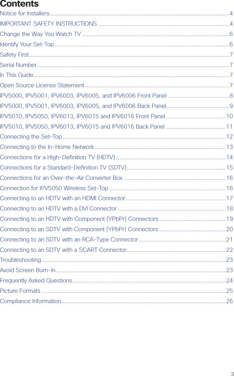
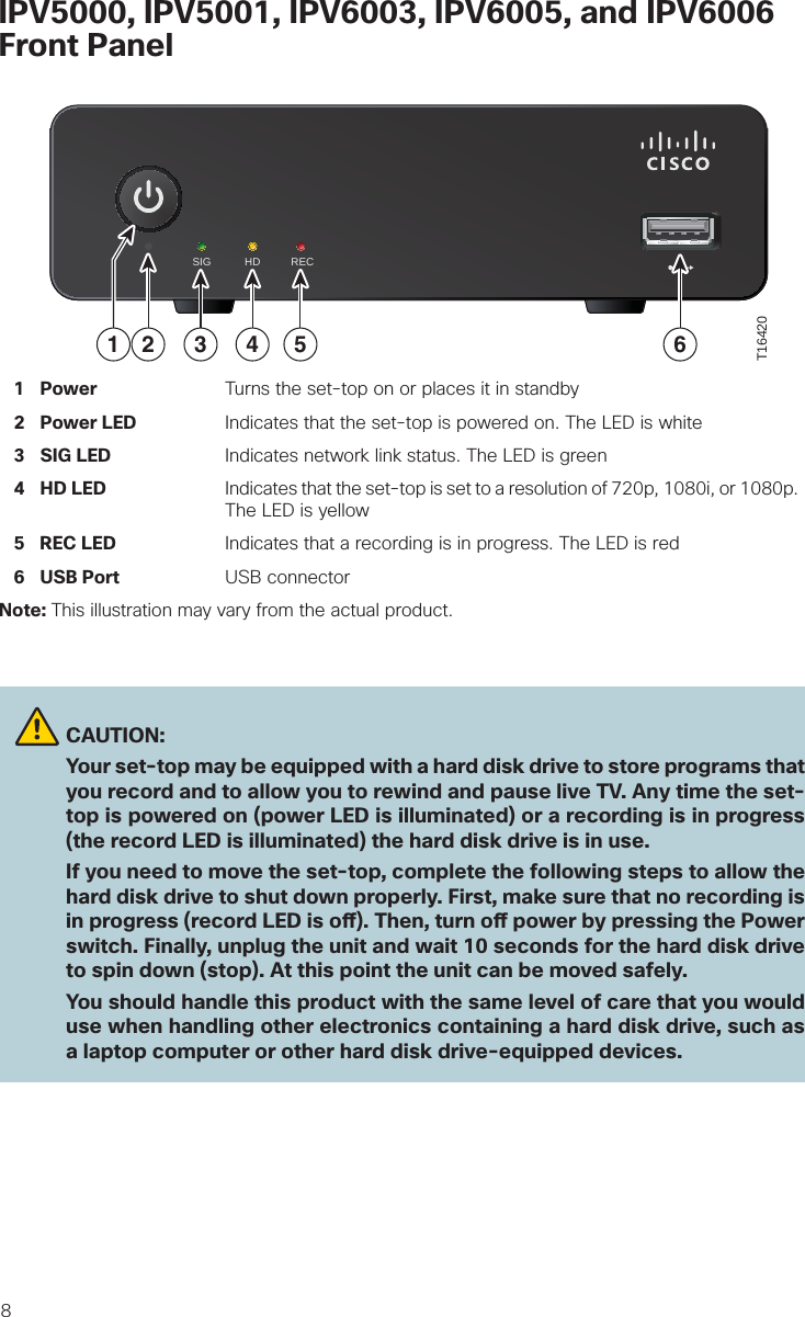
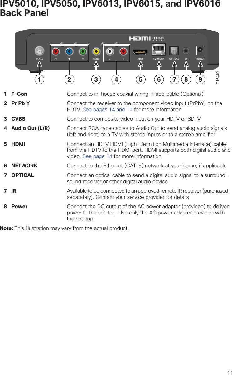
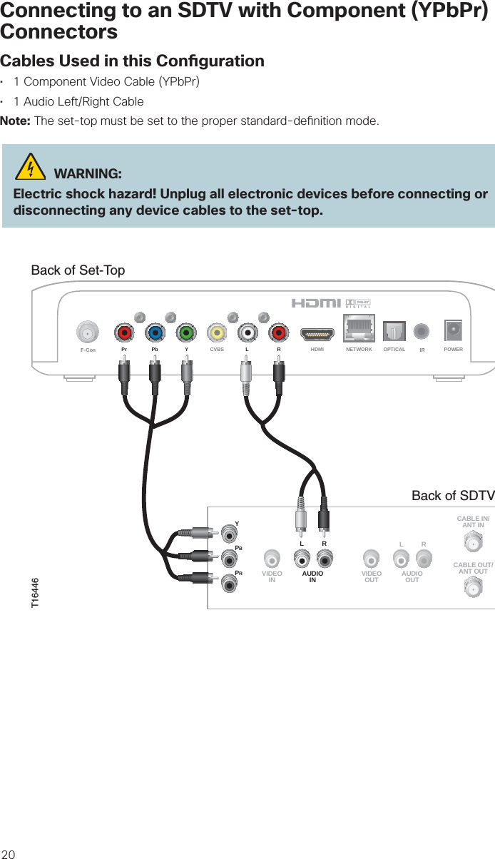
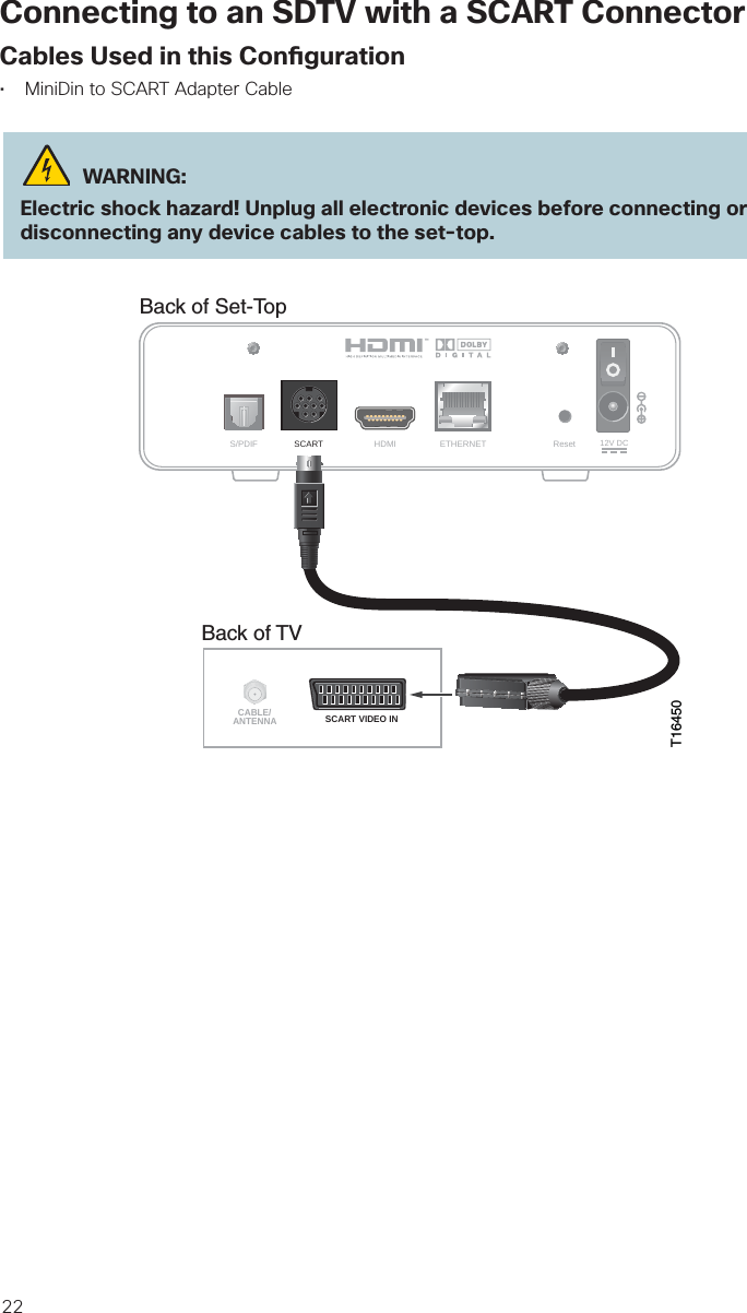
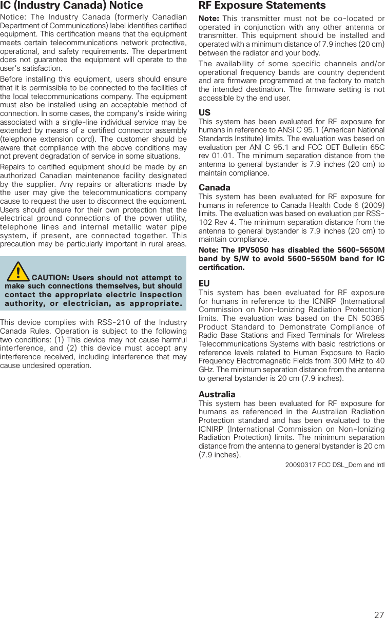
![19Connecting to an HDTV with Component (YPbPr) ConnectorsCables Used in this Con guration• 1 Component Video Cable (YPbPr)• 1 Audio Left/Right Cable (You can also use an optical cable [indicated by the dotted line] insteadof the Audio Left/Right Cable as shown in the diagram, dependent upon your TV’s capabilities.) WARNING:Electric shock hazard! Unplug all electronic devices before connecting or disconnecting any device cables to the set-top.T16445Back of Set-TopLRPr Pb Y CVBS HDMI NETWORK OPTICAL POWERF-Con IRBack ofHDTV HDMIAUDIOCENTERCHANNEL INAUDIO INDVI/HDCPANT (75 )INOUTLRANT-1HD 2YOUTANT-2PBPRLRVIDEOL/MONORL/MONORAUDIOINON OFFS-VIDEOVIDEOAUDIOINHD 1YPBPRLRAUDIOOPTICALINPUTOR](https://usermanual.wiki/PEGATRON/IPV5K6KUSHPNA/User-Guide-2412245-Page-20.png)

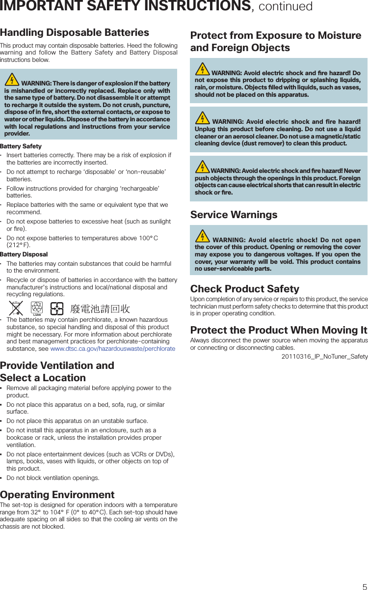
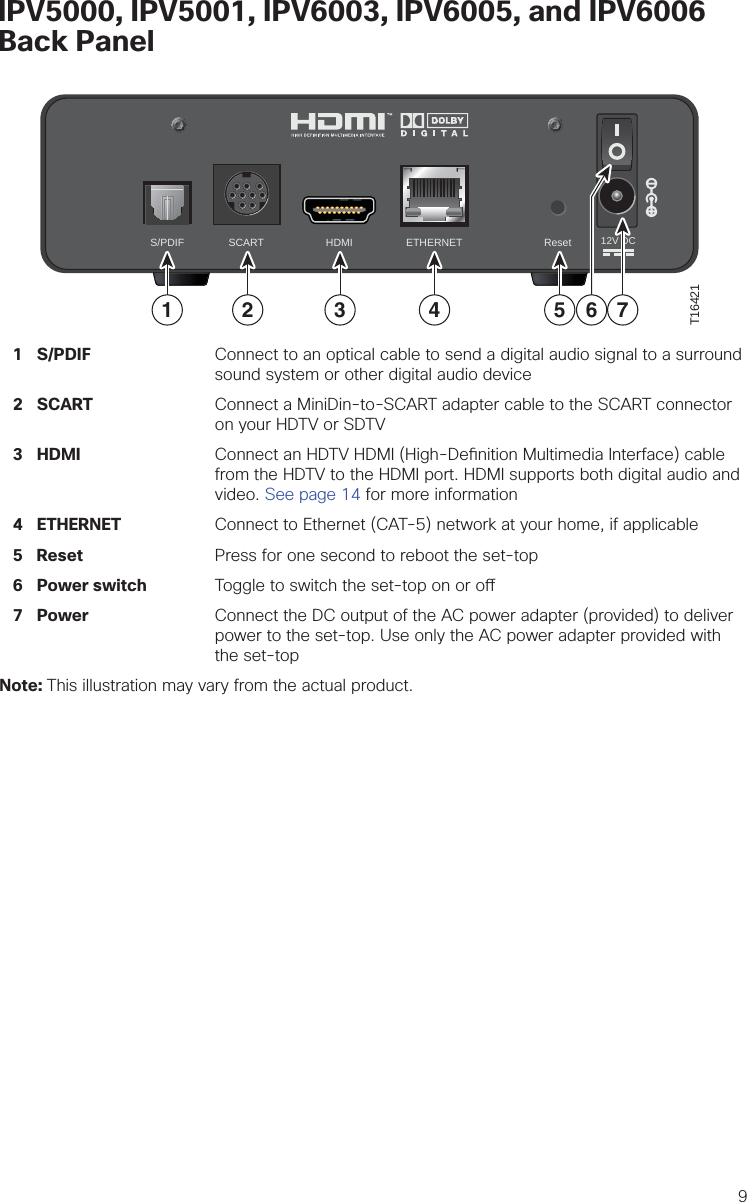
![CE ComplianceDeclaration of Conformity with Regard to the EU Directive 1999/5/EC (R&TTE Directive)This declaration is only valid for configurations (combinations of software, firmware and hardware) supported or provided by Cisco Systems for use within the EU. The use of software or rmware not supported or provided by Cisco Systems may result in the equipment no longer being compliant with the regulatory requirements. Български [Bulgarian]Това оборудване отговаря на съществените изисквания и приложими клаузи на Директива 1999/5/ЕС. Česky [Czech]: Toto zařízení je v souladu se základními požadavky a ostatními odpovídajícími ustanoveními Směrnice 1999/5/EC. Dansk [Danish]: Dette udstyr er i overensstemmelse med de væsentlige krav og andre relevante bestemmelser i Direktiv 1999/5/EF. Deutsch [German]: Dieses Gerät entspricht den grundlegenden Anforderungen und den weiteren entsprechenden Vorgaben der Richtlinie 1999/5/EU.Eesti [Estonian]: See seade vastab direktiivi 1999/5/EÜ olulistele nõuetele ja teistele asjakohastele sätetele. English: This equipment is in compliance with the essential requirements and other relevant provisions of Directive 1999/5/EC. Español [Spanish]: Este equipo cumple con los requisitos esenciales asi como con otras disposiciones de la Directiva 1999/5/CE. Ελληνική [Greek]: Αυτός ο εξοπλισμός είναι σε συμμόρφωση με τις ουσιώδεις απαιτήσεις και άλλες σχετικές διατάξεις της Οδηγίας 1999/5/EC. Français [French]: Cet appareil est conforme aux exigences essentielles et aux autres dispositions pertinentes de la Directive 1999/5/EC. Íslenska [Icelandic]: Þetta tæki er samkvæmt grunnkröfum og öðrum viðeigandi ákvæðum Tilskipunar 1999/5/EC. Italiano [Italian]: Questo apparato é conforme ai requisiti essenziali ed agli altri principi sanciti dalla Direttiva 1999/5/CE. Latviski [Latvian]: Šī iekārta atbilst Direktīvas 1999/5/EK būtiskajām prasībām un citiem ar to saistītajiem noteikumiem. Lietuvių [Lithuanian]: Šis įrenginys tenkina 1999/5/EB Direktyvos esminius reikalavimus ir kitas šios direktyvos nuostatas. Nederlands [Dutch]: Dit apparaat voldoet aan de essentiele eisen en andere van toepassing zijnde bepalingen van de Richtlijn 1999/5/EC. Malti [Maltese]: Dan l-apparat huwa konformi mal-ħtiġiet essenzjali u l-provedimenti l-oħra rilevanti tad-Direttiva 1999/5/EC. Magyar [Hungarian]: Ez a készülék teljesíti az alapvető követelményeket és más 1999/5/EK irányelvben meghatározott vonatkozó rendelkezéseket. Norsk [Norwegian]: Dette utstyret er i samsvar med de grunnleggende krav og andre relevante bestemmelser i EU-direktiv 1999/5/EF. Polski [Polish]: Urządzenie jest zgodne z ogólnymi wymaganiami oraz szczególnymi warunkami określonymi Dyrektywą UE: 1999/5/EC. Português [Portuguese]: Este equipamento está em conformidade com os requisitos essenciais e outras provisões relevantes da Directiva 1999/5/EC. Română [Romanian] Acest echipament este in conformitate cu cerintele esentiale si cu alte prevederi relevante ale Directivei 1999/5/EC. Slovensko [Slovenian]: Ta naprava je skladna z bistvenimi zahtevami in ostalimi relevantnimi pogoji Direktive 1999/5/EC. Slovensky [Slovak]: Toto zariadenie je v zhode so základnými požiadavkami a inými príslušnými nariadeniami direktív: 1999/5/EC. Suomi [Finnish]: Tämä laite täyttää direktiivin 1999/5/EY olennaiset vaatimukset ja on siinä asetettujen muiden laitetta koskevien määräysten mukainen. Svenska [Swedish]: Denna utrustning är i överensstämmelse med de väsentliga kraven och andra relevanta bestämmelser i Direktiv 1999/5/EC. Note: The full declaration of conformity for this product can be found in the Declarations of Conformity and Regulatory Information section of the appropriate product hardware installation guide, which is available at http://www.cisco.com/web/consumer/support/compliance_info.html.The CE mark and class-2 identi er is a xed to the product and its packaging. This product conforms to the following European directives: -1999/5/EC for IPV5050 set-tops-2006/95/EC-2004/108/ECNational RestrictionsThis product operates in the 5 GHz Wi-Fi bands and shall only be used indoors.20110311 CE_Gatewayfor all other IPV5K/IPV6K set-topsCisco and the Cisco logo are trademarks or registered trademarks of Cisco and/or its a liates in the U.S. and other countries. To view a list of Cisco trademarks, go to this URL: www.cisco.com/go/trademarks. Third-party trademarks mentioned are the property of their respective owners. The use of the word partner does not imply a partnership relationship between Cisco and any other company. (1110R)Manufactured under license from Dolby Laboratories. Dolby and the double-D symbol are trademarks of Dolby Laboratories.The terms HDMI and HDMI High-De nition Multimedia Interface, and the HDMI Logo are trademarks or registered trademarks of HDMI Licensing LLC in the United States and other countries.HomePNA is a trademark of HomePNA Alliance.Rovi is a trademark of Rovi Corporation. © 2014 Cisco and/or its a liates. All rights reserved. Last Updated: June 2014 Part Number 78-100350-01A0Printed in China78-100350-01A0](https://usermanual.wiki/PEGATRON/IPV5K6KUSHPNA/User-Guide-2412245-Page-29.png)