PEGATRON IPV5K6KUSHPNA Bluetooth Set-Top Box User Manual Cisco IPV5K IPV6K Set Tops Installation Guide
PEGATRON CORPORATION Bluetooth Set-Top Box Cisco IPV5K IPV6K Set Tops Installation Guide
PEGATRON >
user manual
Print Vendor Remove Before Printing
Printing Specifications
Cisco IPV50xy/IPV60xy Set-Tops Installation
Guide 78-100350-01A0
INLET
Page Size: 8.5 x 11
Color process: Black (1/1) double sided
Paper weight: 60 #
Paper type: Opaque
Varnish: N/A
Number of Pages: 32 (8 signatures)
COVER N/A
BINDING Fold, Saddle Stitch + Trim to finish size 5.5 x 8.5

Cisco
IPV50xy/IPV60xy
High-Defi nition IP
Set-Tops
Installation Guide

2
3
Contents
Notice for Installers ...............................................................................................................4
IMPORTANT SAFETY INSTRUCTIONS .................................................................................4
Change the Way You Watch TV ...........................................................................................6
Identify Your Set-Top ............................................................................................................6
Safety First ............................................................................................................................7
Serial Number .......................................................................................................................7
In This Guide .........................................................................................................................7
Open Source License Statement .........................................................................................7
IPV5000, IPV5001, IPV6003, IPV6005, and IPV6006 Front Panel ......................................8
IPV5000, IPV5001, IPV6003, IPV6005, and IPV6006 Back Panel.......................................9
IPV5010, IPV5050, IPV6013, IPV6015 and IPV6016 Front Panel .....................................10
IPV5010, IPV5050, IPV6013, IPV6015 and IPV6016 Back Panel .....................................11
Connecting the Set-Top .....................................................................................................12
Connecting to the In-Home Network .................................................................................13
Connections for a High-De nition TV (HDTV) ....................................................................14
Connections for a Standard-De nition TV (SDTV) .............................................................15
Connections for an Over-the-Air Converter Box ...............................................................16
Connection for IPV5050 Wireless Set-Top ........................................................................16
Connecting to an HDTV with an HDMI Connector ..............................................................17
Connecting to an HDTV with a DVI Connector ...................................................................18
Connecting to an HDTV with Component (YPbPr) Connectors .........................................19
Connecting to an SDTV with Component (YPbPr) Connectors .........................................20
Connecting to an SDTV with an RCA-Type Connector ......................................................21
Connecting to an SDTV with a SCART Connector .............................................................22
Troubleshooting ..................................................................................................................23
Avoid Screen Burn-In .........................................................................................................23
Frequently Asked Questions ...............................................................................................24
Picture Formats ..................................................................................................................25
Compliance Information ......................................................................................................26
4
1) Read these instructions.
2) Keep these instructions.
3) Heed all warnings.
4) Follow all instructions.
5) Do not use this apparatus near water.
6) Clean only with dry cloth.
7) Do not block any ventilation openings. Install in accordance
with the manufacturer’s instructions.
8) Do not install near any heat sources such as radiators, heat
registers, stoves, or other apparatus (including ampli ers)
that produce heat.
9) Do not defeat the safety purpose of the polarized or
grounding-type plug. A polarized plug has two blades with
one wider than the other. A grounding-type plug has two
blades and a third grounding prong. The wide blade or the
third prong are provided for your safety. If the provided plug
does not fit into your outlet, consult an electrician for
replacement of the obsolete outlet.
10) Protect the power cord from being walked on or pinched
particularly at plugs, convenience receptacles, and the point
where they exit from the apparatus.
11) Only use attachments/accessories specified by the
manufacturer.
12) Use only with the cart, stand, tripod, bracket, or table
specified by the manufacturer, or sold with the
apparatus. When a cart is used, use caution when
moving the cart/apparatus combination to avoid injury from
tip-over.
13) Unplug this apparatus during lightning storms or when unused
for long periods of time.
14) Refer all servicing to quali ed service personnel. Servicing
is required when the apparatus has been damaged in any
way, such as a power-supply cord or plug is damaged, liquid
has been spilled or objects have fallen into the apparatus, the
apparatus has been exposed to rain or moisture, does not
operate normally, or has been dropped.
IMPORTANT SAFETY INSTRUCTIONS
Notice for Installers
The servicing instructions in this notice are for use by quali ed service personnel only. To reduce the risk of electric shock, do not perform
any servicing other than that contained in the operating instructions, unless you are quali ed to do so.
Note to System Installer
For this apparatus, the cable shield/screen shall be grounded as close as practical to the
point of entry of the cable into the building. For products sold in the US and Canada, this
reminder is provided to call the system installer's attention to Article 800-93 and Article
800-100 of the NEC (or Canadian Electrical Code Part 1), which provides guidelines for
proper grounding of the cable shield.
This symbol is intended to alert you that uninsulated voltage within
this product may have sufficient magnitude to cause electric
shock.Therefore, it is dangerous to make any kind of contact with any
inside part of this product.
Ce symbole a pour but d’alerter toute personne qu’un contact avec
une pièce interne de ce produit, sous tension et non isolée, pourrait
être suffisant pour provoquer un choc électrique. Il est donc
dangereux d’être en contact avec toute pièce interne de ce produit.
CAUTION: To reduce the risk of electric shock, do not remove cover (or
back). No user-serviceable parts inside. Refer servicing to qualified service
personnel.
WARNING
T
O PREVENT FIRE OR ELECTRIC SHOCK, DO NOT EXPOSE THIS UNIT
TO RAIN OR MOISTURE.
This symbol is intended to alert you of the presence of important
operating and maintenance (servicing) instructions in the literature
accompanying this product.
Ce symbole a pour but de vous avertir qu’une documentation
importante sur le fonctionnement et l’entretien accompagne ce
produit.
Power Source Warning
A label on this product indicates the correct power source for this
product. Operate this product only from an electrical outlet with
the voltage and frequency indicated on the product label. If you are
uncertain of the type of power supply to your home or business,
consult your service provider or your local power company.
The AC inlet on the unit must remain accessible and operable at
all times.
Ground the Product
WARNING: Avoid electric shock and re hazard! If this
product connects to cable wiring, be sure the cable system
is grounded (earthed). Grounding provides some protection
against voltage surges and built-up static charges.
Protect the Product from Lightning
In addition to disconnecting the AC power from the wall outlet,
disconnect the signal inputs.
Verify the Power Source from the
On/O Power Light
When the on/o power light is not illuminated, the apparatus may
still be connected to the power source. The light may go out when
the apparatus is turned o , regardless of whether it is still plugged
into an AC power source.
Eliminate AC Power/Mains Overloads
WARNING: Avoid electric shock and re hazard! Do
not overload AC power/mains, outlets, extension cords, or
integral convenience receptacles. For products that require
battery power or other power sources to operate them,
refer to the operating instructions for those products.
5
Protect from Exposure to Moisture
and Foreign Objects
WARNING: Avoid electric shock and re hazard! Do
not expose this product to dripping or splashing liquids,
rain, or moisture. Objects lled with liquids, such as vases,
should not be placed on this apparatus.
WARNING: Avoid electric shock and fire hazard!
Unplug this product before cleaning. Do not use a liquid
cleaner or an aerosol cleaner. Do not use a magnetic/static
cleaning device (dust remover) to clean this product.
WARNING: Avoid electric shock and re hazard! Never
push objects through the openings in this product. Foreign
objects can cause electrical shorts that can result in electric
shock or re.
Service Warnings
WARNING: Avoid electric shock! Do not open
the cover of this product. Opening or removing the cover
may expose you to dangerous voltages. If you open the
cover, your warranty will be void. This product contains
no user-serviceable parts.
Check Product Safety
Upon completion of any service or repairs to this product, the service
technician must perform safety checks to determine that this product
is in proper operating condition.
Protect the Product When Moving It
Always disconnect the power source when moving the apparatus
or connecting or disconnecting cables.
20110316_IP_NoTuner_Safety
IMPORTANT SAFETY INSTRUCTIONS, continued
Handling Disposable Batteries
This product may contain disposable batteries. Heed the following
warning and follow the Battery Safety and Battery Disposal
instructions below.
WARNING: There is danger of explosion if the battery
is mishandled or incorrectly replaced. Replace only with
the same type of battery. Do not disassemble it or attempt
to recharge it outside the system. Do not crush, puncture,
dispose of in re, short the external contacts, or expose to
water or other liquids. Dispose of the battery in accordance
with local regulations and instructions from your service
provider.
Battery Safety
• Insert batteries correctly. There may be a risk of explosion if
the batteries are incorrectly inserted.
• Do not attempt to recharge ‘disposable’ or ‘non-reusable’
batteries.
• Follow instructions provided for charging ‘rechargeable’
batteries.
• Replace batteries with the same or equivalent type that we
recommend.
• Do not expose batteries to excessive heat (such as sunlight
or re).
• Do not expose batteries to temperatures above 100°C
(212°F).
Battery Disposal
• The batteries may contain substances that could be harmful
to the environment.
• Recycle or dispose of batteries in accordance with the battery
manufacturer’s instructions and local/national disposal and
recycling regulations.
• The batteries may contain perchlorate, a known hazardous
substance, so special handling and disposal of this product
might be necessary. For more information about perchlorate
and best management practices for perchlorate-containing
substance, see www.dtsc.ca.gov/hazardouswaste/perchlorate
Provide Ventilation and
Select a Location
• Remove all packaging material before applying power to the
product.
• Do not place this apparatus on a bed, sofa, rug, or similar
surface.
• Do not place this apparatus on an unstable surface.
• Do not install this apparatus in an enclosure, such as a
bookcase or rack, unless the installation provides proper
ventilation.
• Do not place entertainment devices (such as VCRs or DVDs),
lamps, books, vases with liquids, or other objects on top of
this product.
• Do not block ventilation openings.
Operating Environment
The set-top is designed for operation indoors with a temperature
range from 32° to 104° F (0° to 40°C). Each set-top should have
adequate spacing on all sides so that the cooling air vents on the
chassis are not blocked.
6
Change the Way You Watch TV
Welcome to Internet Protocol Television (IPTV). The Cisco IPV5K/IPV6K Series High-De nition IP Set-Tops
bring a rich, new set of interactive services directly to you through your TV and your in-home IP network.
Available services may include some or all of the following features:
• Digital Video Recorder (DVR)—Allows you to record your favorite programs so that you can still go
to your friend’s house for dinner and not miss your favorite TV show
• Pause Live TV—Allows you to pay for the pizza and come back to the show where you left it
(Applies to DVR models only)
• High-de nition (HD)—Provides crystal-clear pictures and sound when compared to standard-
de nition – you won’t want to watch television any other way once you’ve experienced HD
• Video-On-Demand (VOD)—Gives you access to a robust library of movies and programs that you
can watch – when you want to watch them
Note: Contact your service provider to nd out if the DVR, HD, or VOD services are available and to
activate the services.
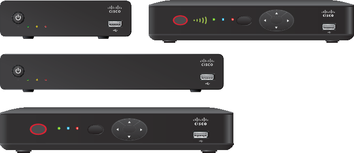
Identify Your Set-Top
This installation guide covers the following set-top models. Use the following information to identify
your model.
• IPV5000 set-top—TV set-top that supports high-de nition (HD) and standard-de nition (SD)
video MPEG2 and H.264 decoding. Supports 480i, 576i, 720p, 1080i and 1080p content. Uses
Ethernet over CAT-5
• IPV5001 set-top—The IPV5001 is the same as the IPV5000 but has 16 GB of eMMC ash memory
• IPV5010 set-top—The IPV5010 is the same as the IPV5000 but also uses HPNA v3 in-home
networking over coaxial cable
• IPV5050 set-top—The IPV5050 is the same as the IPV5000 but with WiFi capability
• IPV6003 set-top—The IPV6003 is the same as the IPV5000 but with a 320 GB hard disk drive for
DVR capability
• IPV6005 set-top—The IPV6005 is the same as the IPV5000 but with a 500 GB hard disk drive for
DVR capability
• IPV6006 set-top—The IPV6006 is the same as the IPV5000 but with a 1 TB hard disk drive for
DVR capability
• IPV6013 set-top—The IPV6013 is the same as the IPV5000 but with HPNA v3 in-home
networking over coaxial cable and a 320 GB hard disk drive for DVR capability
• IPV6015 set-top—The IPV6015 is the same as the IPV5000 but with HPNA v3 in-home
networking over coaxial cable and a 500 GB hard disk drive for DVR capability
• IPV6016 set-top—The IPV6016 is the same as the IPV5000 but with HPNA v3 in-home
networking over coaxial cable and a 1 TB hard disk drive for DVR capability
IPV5000 / IPV5001 IPV5010 / IPV5050
T16422
IPV6013 / IPV6015 / IPV6016
POWER
LINK HD REC
OK
MENU
POWER
LINK HD REC
OK
MENU
SIG HD REC
IPV6003 / IPV6005 / IPV6006
LINK HD REC Note: This illustration
may vary from the
actual product.
7
Safety First
Before using the set-top, read the Important Safety Instructions section of this guide.
Serial Number
At times your service provider may ask for the serial number. To nd the serial number for your set-
top, look on the bottom of the set-top for the label. The serial number is a 9-digit numeric code to
the right of the letters “S/N” on the label.
Use the space provided here to record the serial number: _______________________________
In This Guide
This guide covers the information that you need to connect your set-top to both your in-home IP
network and your entertainment system. The guide also outlines certain safeguards and installation
information. The safety information contained in this guide was developed and provided solely by the
set-top manufacturer, Cisco Systems, Inc.
Open Source License Statement
Cisco IPV5K and IPV6K Series set-tops may contain, in part, certain free and/or open source
software (“Open Source”) under separate license terms. Examples of such licenses may include
all versions of the GNU General Public License (GPL), GNU Lesser General Public License (LGPL),
BSD license, MIT license, Mozilla Public License, Eclipse Public License, Apache license, and
others. To nd speci c information regarding the Open Source in your product, including copies of
the applicable license documentation and related information, go to: (i) for North America http://
www.cisco.com/web/consumer/support/open_source.html, or (ii) for outside North America http://
www.cisco.com/web/consumer/support/open_source.html#~international. Once at the site, search
for the product listing and click the related items identi ed. If you have any questions or problems
accessing any of the links, contact: spvtg-external-opensource-requests@cisco.com.
8
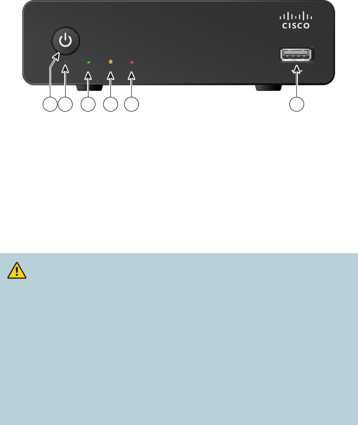
IPV5000, IPV5001, IPV6003, IPV6005, and IPV6006
Front Panel
1 Power Turns the set-top on or places it in standby
2 Power LED Indicates that the set-top is powered on. The LED is white
3 SIG LED Indicates network link status. The LED is green
4 HD LED Indicates that the set-top is set to a resolution of 720p, 1080i, or 1080p.
The LED is yellow
5 REC LED Indicates that a recording is in progress. The LED is red
6 USB Port USB connector
Note: This illustration may vary from the actual product.
CAUTION:
Your set-top may be equipped with a hard disk drive to store programs that
you record and to allow you to rewind and pause live TV. Any time the set-
top is powered on (power LED is illuminated) or a recording is in progress
(the record LED is illuminated) the hard disk drive is in use.
If you need to move the set-top, complete the following steps to allow the
hard disk drive to shut down properly. First, make sure that no recording is
in progress (record LED is o ). Then, turn o power by pressing the Power
switch. Finally, unplug the unit and wait 10 seconds for the hard disk drive
to spin down (stop). At this point the unit can be moved safely.
You should handle this product with the same level of care that you would
use when handling other electronics containing a hard disk drive, such as
a laptop computer or other hard disk drive-equipped devices.
SIG HD REC
T16420
1 2 3 4 5 6
9
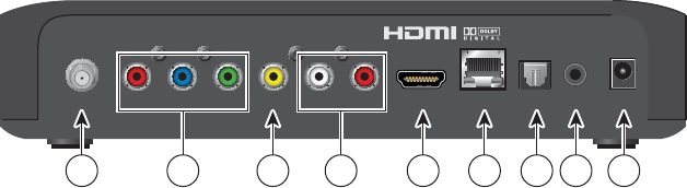
IPV5000, IPV5001, IPV6003, IPV6005, and IPV6006
Back Panel
1 S/PDIF Connect to an optical cable to send a digital audio signal to a surround
sound system or other digital audio device
2 SCART Connect a MiniDin-to-SCART adapter cable to the SCART connector
on your HDTV or SDTV
3 HDMI Connect an HDTV HDMI (High-De nition Multimedia Interface) cable
from the HDTV to the HDMI port. HDMI supports both digital audio and
video. See page 14 for more information
4 ETHERNET Connect to Ethernet (CAT-5) network at your home, if applicable
5 Reset Press for one second to reboot the set-top
6 Power switch Toggle to switch the set-top on or o
7 Power Connect the DC output of the AC power adapter (provided) to deliver
power to the set-top. Use only the AC power adapter provided with
the set-top
Note: This illustration may vary from the actual product.
S/PDIF SCART HDMI ETHERNET Reset 12V DC
T16421
61 2 3 4 5 7
10
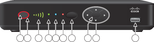
IPV5010, IPV5050, IPV6013, IPV6015, and IPV6016
Front Panel
1 Power Turns the set-top on or places it in standby
2 LED halo LED is green for power on, red for standby
3 Signal Strength Identi es the strength of the wireless connection (Optional)
Indicator
4 LINK Indicates network link status. The LED is green
5 HD Indicates the set-top is set to a resolution of 720p, 1080i, or 1080p.
The LED is blue
6 REC Indicates that a recording is in progress. The LED is red
7 MENU Accesses the on-screen menu
8 OK Selects the current item
9 Arrow Keys Accesses on-screen services (such as the on-screen guide,
video-on-demand, or pay-per-view) and navigates menus
10 USB Port USB connector
Note: This illustration may vary from the actual product.
POWER
LINK HD REC
OK
MENU
T16439
21 3 4 5 6 7 109
8
11
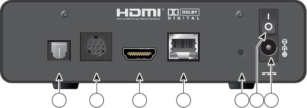
IPV5010, IPV5050, IPV6013, IPV6015, and IPV6016
Back Panel
1 F-Con Connect to in-house coaxial wiring, if applicable (Optional)
2 Pr Pb Y Connect the receiver to the component video input (PrPbY) on the
HDTV. See pages 14 and 15 for more information
3 CVBS Connect to composite video input on your HDTV or SDTV
4 Audio Out (L/R) Connect RCA-type cables to Audio Out to send analog audio signals
(left and right) to a TV with stereo inputs or to a stereo ampli er
5 HDMI Connect an HDTV HDMI (High-De nition Multimedia Interface) cable
from the HDTV to the HDMI port. HDMI supports both digital audio and
video. See page 14 for more information
6 NETWORK Connect to the Ethernet (CAT-5) network at your home, if applicable
7 OPTICAL Connect an optical cable to send a digital audio signal to a surround-
sound receiver or other digital audio device
7 IR Available to be connected to an approved remote IR receiver (purchased
separately). Contact your service provider for details
8 Power Connect the DC output of the AC power adapter (provided) to deliver
power to the set-top. Use only the AC power adapter provided with
the set-top
Note: This illustration may vary from the actual product.
LRPr Pb Y CVBS HDMI NETWORK OPTICAL POWER
F-Con IR
T16440
1 3 5 6 7 8 92 4
12
Because the connections
for a high-de nition (HD)
or standard-de nition (SD)
TV are di erent, you must
determine if your TV is HD
or SD. Your TV must
receive HD signals for
you to enjoy the bene ts
of HDTV. See the guide that came with your TV for more information.
See page 25 for more information on picture formats.
Make one of the following connections for your home network:
• If your home network uses coaxial cable, use the F-Con connector on the set-
top. See page 13
• If your home network uses Ethernet (CAT-5) cable, use the NETWORK
connector on the set-top. See page 13
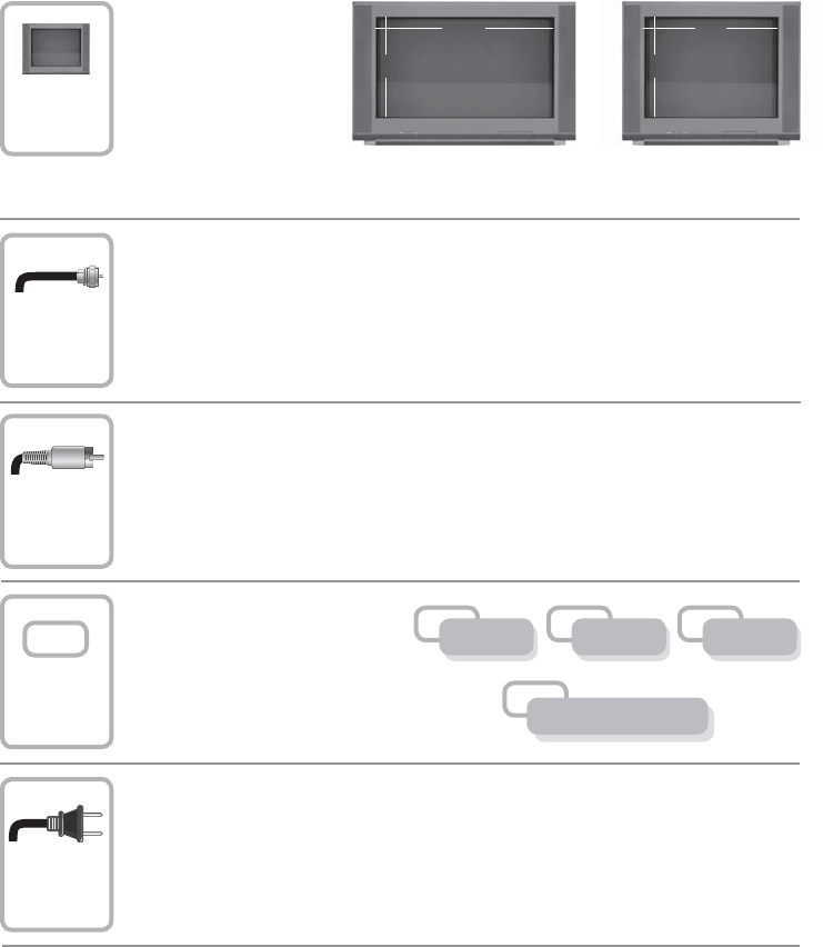
Connecting the Set-Top
To connect your set-top to your network and home entertainment devices, complete these steps:
Identify the additional consumer
electronic devices that you will
connect to the set-top and TV.
See pages 17 through 22 and
see the owner’s manual for the
device.
Plug the set-top and the TV into an AC power source that is not controlled by a
switch.
Make the connections for your TV, VCR, and DVD recorder as follows:
• If you are using an HDTV, see page 14 and the connection diagrams in this
guide
•If you are using an SDTV, see page 15 and the connection diagrams in this
guide
1
2
3
5
4
Home Theater
OtherDVDVCR
9
16 4
3
or
13
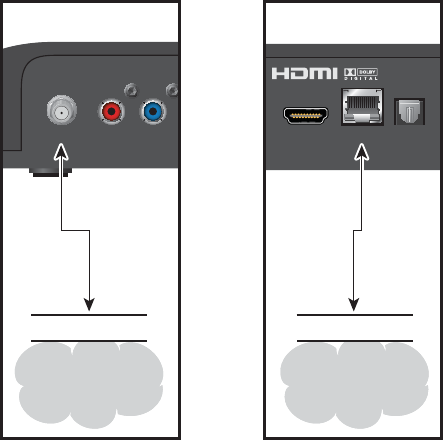
Connecting to the In-Home Network
The following diagrams illustrate examples of the connections that you can use to connect your
set-top to your in-home network. Contact your service provider for the recommended connection
method for your home. (This section does not apply to the IPV5050; see Connection for IPV5050
Wireless Set-Top on page 16.)
Notes:
•The in-home coaxial wiring networks use HomePNA 3.1 technology
• The illustrations below may vary from the actual product
Pr Pb
F-Con HDMI NETWORK OPTICAL
In-Home
Coaxial
Network
Wall
OR
CAT-5
In-Home
CAT-5
Network
Wall
T16441
Coaxial
14
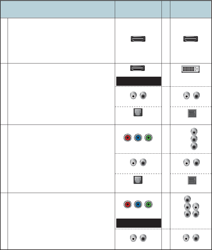
Connections for a High-De nition TV (HDTV)
To use the set-top with an HDTV, you must make one of the following connections to view the
HD content. See the owner’s manual for your TV and the cabling diagrams in this guide for more
detailed connection information.
Although all connections provide you with quality service, we list the connections in our
recommended order.
Notes:
• The labeling on your set-top or HDTV may vary slightly from the illustrations shown below
• Some cables shown in the connection diagrams may not be included with this set-top
• Set the HD mode and select the output video format (480i, 480p, 720p, 1080i, 1080p) on the set-top.
See page 25 for more information on picture formats
Some HDTVs have a High-De nition Multimedia
Interface (HDMI) connector. The HDMI connector
provides both a digital video and audio connection.
See the connection diagram on page 17 for an
example.
Note: The HDMI port on the TV must support
high-bandwidth digital content protection (HDCP).
HDTV
Connections
The HDMI connector can provide the connection
to an HDTV with a DVI input. If your HDTV has a
Digital Visual Interface (DVI) connector, you need
an HDMI-to-DVI adapter, and a separate audio
connection (either L/R or optical audio).
Note: The DVI port on the TV must support
high-bandwidth digital content protection (HDCP).
See the connection diagram on page 18 for an
example.
Use One of These Required
Connections to an HDTV
HDMI
HDMI
HDMI
DVI
Set-Top
Connections
The YPbPr (red, blue, and green) connectors
provide high-de nition component video signals
to an HDTV, and a separate audio connection
(either L/R or optical audio).
See the connection diagram on page 19 for an
example.
Pr
Pb
Y
Audio/VideoVideoVideo
DVI HDMIYPbPr
Some HDTVs have only RGB or RGB-HV
connectors. If you have one of these HDTVs,
you need a Component-to-RGB adapter, and
you need a separate audio connection.
B
G
V
H
R
Adapter Needed
Adapter Needed
Video
RGB
Audio
LR
AUDIO
OUT
LR
AUDIO
OUT
LR
OPTICAL
OPTICAL
INPUT
LR
Audio
AUDIO
OUT
LR
OPTICAL
OPTICAL
INPUT
LR
Audio
or S/PDIF
Pr Pb Y
Pr Pb Y
or S/PDIF
15
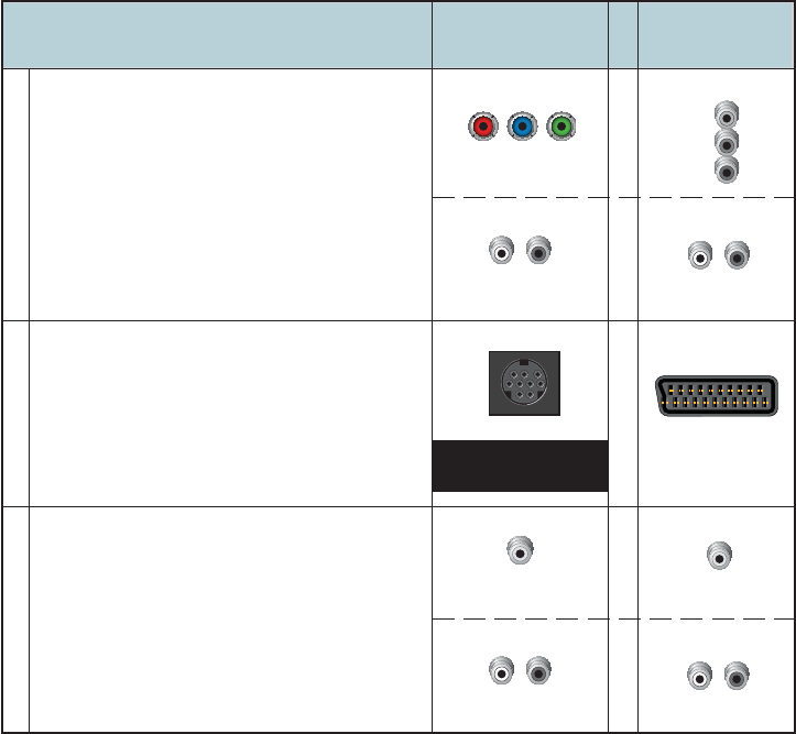
Connections for a Standard-De nition TV (SDTV)
When using the set-top with an SDTV, you must make one of the following connections to view
content. Some SDTVs may not have all of these connections. See the owner’s manual for your TV
and the cabling diagrams in this guide for more detailed information.
Although all connections provide you with quality service, we list the connections in our
recommended order.
Notes:
• The labeling on your set-top or SDTV may vary slightly from the illustrations shown below
• Some cables shown in the connection diagrams may not be included with this set-top
The YPbPr (red, blue, and green) connectors
can provide standard-de nition component
video signals to an SDTV. A separate audio
connection is also needed.
Note: To connect YPbPr to an SDTV, you
must select the output video format. See page
25 for more information on picture formats.
See the connection diagram on page 20 for
an example.
SDTV
Connections
Use One of These Required
Connections to an SDTV
Set-Top
Connections
The MiniDin connector can provide standard-
de nition RGB or composite video signals and
audio to SDTV or HDTV.
See the connection diagram on page 22 for
an example.
The Video Out connector provides a video
connection to an SDTV. A separate audio
connection is also needed.
See the connection diagram on page 21 for
an example.
SCART
Video Out
VIDEO
OUT
VIDEO
IN
LR
Pr
Pb
Y
LR
YPbPr
Audio VideoAudio Video
AUDIO
OUT
LR
AUDIO
OUT
LR
Audio/Video
SCART
SCART
Adapter Cable
Needed
or CUBS
Pr Pb Y
16
Connections for an Over-the-Air Converter Box
You can connect an over-the-air converter box directly to your TV to receive certain local
channels, but do not connect the over-the-air converter box directly to your set-top.
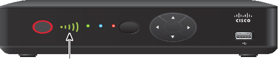
Connection for IPV5050 Wireless Set-Top
The IPV5050 set-top allows for easy and secure establishment of a wireless home network. The
signal strength indicator on the front panel of the set-top allows you to identify the strength of your
wireless connection.
T16442
POWER
LINK HD REC
OK
MENU
Signal Strength
Indicator
17
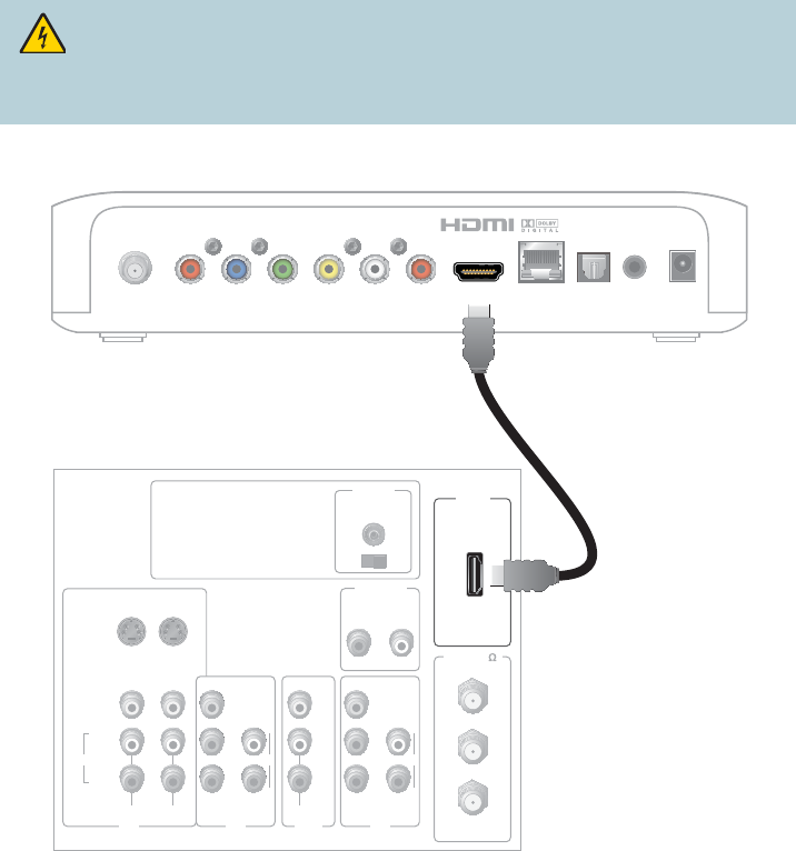
Connecting to an HDTV with an HDMI Connector
Cable Used in this Con guration
• 1 HDMI Cable
Notes:
•The HDMI port on the TV must support high-bandwidth digital content protection (HDCP)
• The HDMI interface supports Dolby Digital 5.1 audio
WARNING:
Electric shock hazard! Unplug all electronic devices before connecting or
disconnecting any device cables to the set-top.
Back of Set-Top
T16443
LRPr Pb Y CVBS HDMI NETWORK OPTICAL POWER
F-Con IR
Back of HDTV
HDMI
AUDIO
CENTER
CHANNEL IN
AUDIO IN
DVI/HDCP
ANT (75 )
INOUT
LR
ANT-1
HD 2
Y
OUT
ANT-2
PB
PR
L
R
VIDEO
L/
MONO
R
L/
MONO
R
AUDIO
IN
ON OFF
IN
HD 1
S-VIDEO
VIDEO Y
PB
PR
L
R
AUDIOAUDIO
18
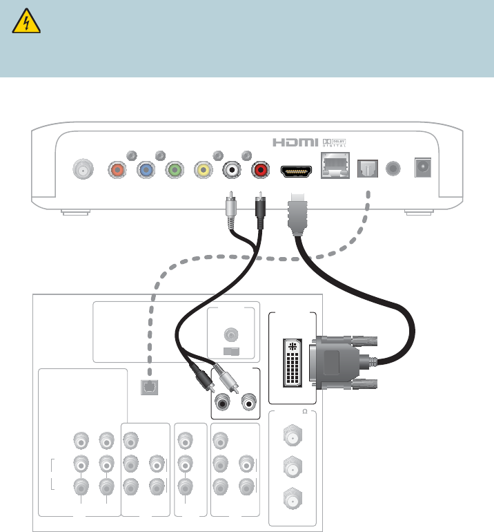
Connecting to an HDTV with a DVI Connector
Cables Used in this Con guration
• 1 HDMI-to-DVI Cable or 1 HDMI Cable and 1 HDMI-to-DVI Adapter
• 1 Audio Left/Right Cable (You can also use an optical cable [indicated by the dotted line] instead
of the Audio Left/Right Cable as shown in the diagram, dependent upon your TV’s capabilities.)
Notes:
• The DVI port on the TV must support high-bandwidth digital content protection (HDCP)
• When you connect the HDMI connector to the DVI connector on your HDTV, you need an
HDMI-to-DVI adapter and a separate audio connection
WARNING:
Electric shock hazard! Unplug all electronic devices before connecting or
disconnecting any device cables to the set-top.
Back of Set-Top
LRPr Pb Y CVBS HDMI NETWORK OPTICAL POWER
F-Con IR
Back of HDTV
AUDIO
CENTER
CHANNEL IN
ANT (75 )
INOUT
ANT-1
HD 2
Y
OUT
ANT-2
PB
PR
L
R
VIDEO
L/
MONO
R
L/
MONO
R
AUDIO
IN
ON OFF
IN
HD 1
S-VIDEO
VIDEO Y
PB
PR
L
R
AUDIOAUDIO
DVI/HDCP
IN
AUDIO IN
DVI/HDCP
LR
OPTICAL
INPUT
OR
T16444
19
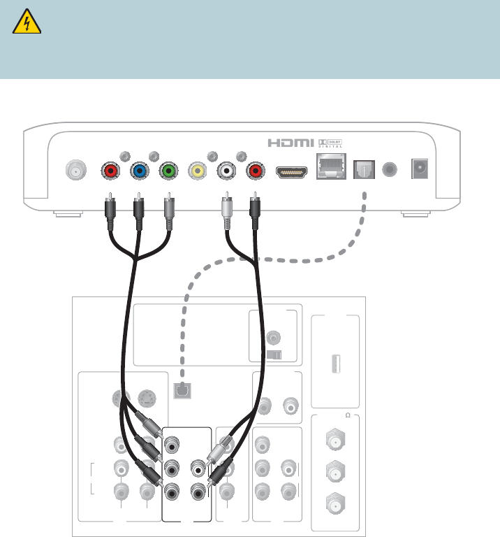
Connecting to an HDTV with Component (YPbPr)
Connectors
Cables Used in this Con guration
• 1 Component Video Cable (YPbPr)
• 1 Audio Left/Right Cable (You can also use an optical cable [indicated by the dotted line] instead
of the Audio Left/Right Cable as shown in the diagram, dependent upon your TV’s capabilities.)
WARNING:
Electric shock hazard! Unplug all electronic devices before connecting or
disconnecting any device cables to the set-top.
T16445
Back of Set-Top
LRPr Pb Y CVBS HDMI NETWORK OPTICAL POWER
F-Con IR
Back of
HDTV HDMI
AUDIO
CENTER
CHANNEL IN
AUDIO IN
DVI/HDCP
ANT (75 )
INOUT
LR
ANT-1
HD 2
Y
OUT
ANT-2
PB
PR
L
R
VIDEO
L/
MONO
R
L/
MONO
R
AUDIO
IN
ON OFF
S-VIDEO
VIDEO
AUDIO
IN
HD 1
Y
PB
PR
L
R
AUDIO
OPTICAL
INPUT
OR
20
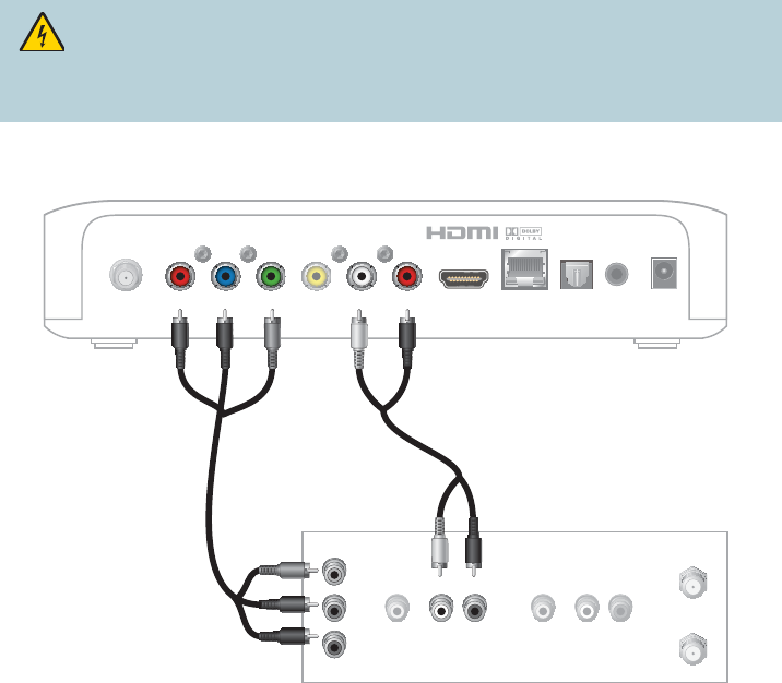
Connecting to an SDTV with Component (YPbPr)
Connectors
Cables Used in this Con guration
• 1 Component Video Cable (YPbPr)
• 1 Audio Left/Right Cable
Note: The set-top must be set to the proper standard-de nition mode.
WARNING:
Electric shock hazard! Unplug all electronic devices before connecting or
disconnecting any device cables to the set-top.
Back of Set-Top
LRPr Pb Y CVBS HDMI NETWORK OPTICAL POWER
F-Con IR
Back of SDTV
CABLE OUT/
ANT OUT
CABLE IN/
ANT IN
RL
AUDIO
IN
VIDEO
IN
RL
AUDIO
OUT
VIDEO
OUT
Y
PB
PR
T16446
21
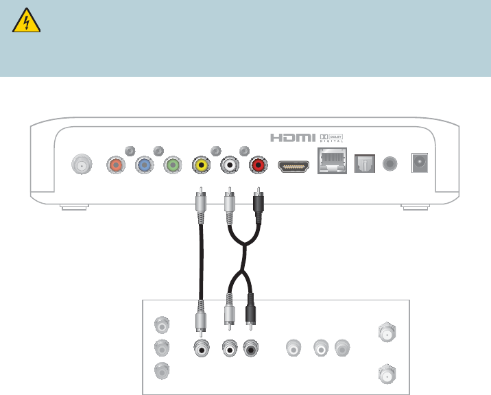
Connecting to an SDTV with an RCA-Type Connector
Cables Used in this Con guration
• 1 RCA-type Video Cable
• 1 Audio Left/Right Cable
WARNING:
Electric shock hazard! Unplug all electronic devices before connecting or
disconnecting any device cables to the set-top.
T16447
Back of Set-Top
LRPr Pb Y CVBS HDMI NETWORK OPTICAL POWER
F-Con IR
CABLE OUT/
ANT OUT
RL
AUDIO
IN
VIDEO
IN
RL
AUDIO
OUT
VIDEO
OUT
Y
PB
PR
CABLE IN/
ANT IN
Back of SDTV
22
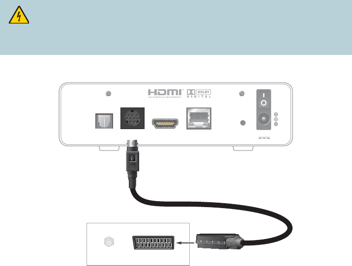
Connecting to an SDTV with a SCART Connector
Cables Used in this Con guration
• MiniDin to SCART Adapter Cable
WARNING:
Electric shock hazard! Unplug all electronic devices before connecting or
disconnecting any device cables to the set-top.
Back of Set-Top
S/PDIF SCART HDMI ETHERNET Reset 12V DC
CABLE/
ANTENNA SCART VIDEO IN
Back of TV
CABLE/
ANTENNA SCART VIDEO IN
T16450

23
Troubleshooting
If the set-top does not perform as expected, the following tips may help. If you need further assistance,
contact your service provider.
No Picture
• Verify that the power to your TV is turned on
• If the set-top is plugged into a wall switch, verify that the switch is in the ON position
• Verify that all cables are properly connected
• If your system includes a VCR, DVD recorder, or stereo, verify that you have properly connected
the device to the set-top
• Verify that you are using the proper input selection to the home theater set-top or TV
• Verify that the set-top is set to the proper screen type and resolution
• If you are using coaxial cable to connect to your TV, verify that the TV is tuned to the channel
designated by your service provider (usually channel 3). Contact your service provider for the
channel information
No Color or Incorrect Color
• Verify that the current TV program is broadcast in color
• Adjust the TV color controls
• If you are using a component video connection (YPbPr), check that all connectors are completely
and properly plugged into the set-top and TV
• If you are using a component video connection (YPbPr) and your HDTV has only RGB or RGB-HV
connectors, you must use an adapter. You can obtain the adapter through an electronic parts
retailer
No Sound
• If your setup includes a VCR, DVD recorder, or stereo, verify that you have properly connected
the device to the set-top
• Verify that the volume is turned up
• Verify that the mute function is not on
• Verify the proper input selection to the home theater set-top or TV
• If you are using coaxial cable to connect to your TV, verify that the TV is tuned to the correct channel
Avoid Screen Burn-In
Images such as letterbox bars or side bars, bright closed-captioning backgrounds, station logos, or
any other stationary images may cause the display in your HDTV to age unevenly; this is known as
screen burn-in. See the owner’s manual that came with your HDTV for more information.
CAUTION:
Avoid screen burn-in.
Do not display the same xed images on your HDTV screen for extended periods
of time.
24
Frequently Asked Questions
What Is Digital Television?
Digital television (DTV) is a huge leap forward in television technology compared to analog television
that has been widely available since the 1940s. DTV is delivered and displayed using digital encoding,
similar to the way a PC operates. By using digital technology, there is no variation in picture and
sound quality from the origination point until it is displayed on your television. You always receive a
high-quality picture without the wavy lines or static you might sometimes get from a weak analog
signal. Another feature of digital television is digital surround sound using Dolby Digital technology,
which is the same technology used to produce the sound you hear in movie theaters.
What Is Standard-De nition Television?
Standard-de nition television (SDTV) is a television system that uses a resolution that is not
considered to be high-de nition television (HDTV 720p, 1080i, and 1080p). The two common
SDTV signal types are 576i, with 576 interlaced lines of resolution, derived from the European-
developed PAL and SECAM systems; and 480i, with 480 interlaced lines of resolution, based on the
American National Television System Committee (NTSC) system.
In North America, digital SDTV is broadcast in the same 4:3 aspect ratio as NTSC signals. In other
parts of the world that used the PAL or SECAM color systems, standard-de nition television is now
usually shown with a 16:9 aspect ratio.
What Is High-De nition Television?
High-De nition Television (HDTV) is a high-quality video standard developed to replace older video
formats often referred to as SDTV (Standard-de nition television). While HDTV’s video quality is
one of the most noticeable improvements over SDTV, HDTV includes a number of other important
improvements as well.
First of all instead of an analog signal, used by traditional NTSC broadcasts, HDTV is always digital.
This eliminates analog interference caused be electrical currents and magnetic elds. Secondly, HDTV
uses a di erent aspect ratio than SDTV. While previous broadcasts used a 4:3 ratio, HDTV uses a ratio
of 16:9. This wider aspect ratio more closely emulates how humans see the world, making the image
appear more realistic. This ratio is also better for watching widescreen movies, which are recorded in
widescreen for the same reason. HDTV signals are either 720p, 1080i or 1080p.
Are Local TV Stations or Other Programmers Broadcasting in HDTV?
Many local TV stations and programmers are transmitting digital signals. However, transmitting
a digital signal does not mean transmitting an HDTV signal. Some stations are using the new
bandwidth to broadcast several standard-de nition channels. Most stations and programmers, once
they begin broadcasting in digital, are o ering HD content from their parent network (for example,
CBS, ABC, NBC, Fox, and PBS). Contact your service provider for more information.
Why Aren’t All of the Shows that I Watch in High-De nition?
A high-de nition program must originate in HD format and be broadcast in HD format. Having an
HDTV system does not mean that everything you watch will be viewed in high-de nition. Getting the
signal from a digital source also does not mean it is high-de nition.
What Is HDMI and Does it Support Dolby Digital 5.1 Audio?
The High-De nition Multimedia Interface (HDMI) is an uncompressed, all-digital audio/video
interface. The Dolby Digital audio format that provides up to 5.1 separate channels of surround
sound, and is the standard used for DVD-Video. HDMI supports standard, enhanced, or high-
de nition video, plus multi-channel digital audio, such as Dolby Digital audio, on a single cable.
25
Picture Formats
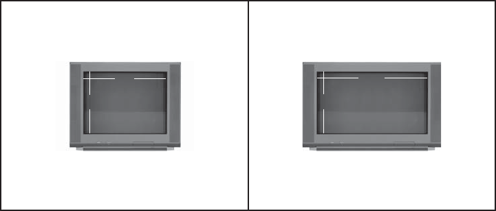
What Is the Di erence Between a Standard-Screen and a Wide-
Screen HDTV?
The type of screen your HDTV has (wide-screen or standard-screen) determines how the set-top
displays programs on the screen. The picture format for an HDTV is a combination of aspect ratio
and screen resolution and is di erent for standard-screen and wide-screen HDTVs.
What Is Aspect Ratio?
An aspect ratio is the ratio of the width to the height of the TV screen. The aspect ratios di er
because the television industry manufactures both standard-screen and wide-screen HDTVs to
appeal to consumer viewing preferences.
What Is the Screen Resolution?
The screen resolution indicates the amount of detail that the picture displays. Resolution is identi ed
by the number of display lines on the screen. The techniques that an HDTV uses to “paint” the
picture on the screen are referred to as progressive and interlaced.
With the progressive scanning method, the lines are drawn on the screen one at a time in
sequential order. Progressive scanning results in a more detailed image on the screen and is also less
susceptible to the icker commonly associated with interlaced scanning. The interlaced method
involves refreshing pixels in alternation — rst the odd lines and then the even lines.
For advanced setup, select the screen resolution that your TV can support. See your HDTV user
manuals to choose the proper screen resolution (480i, 576i, 720p, 1080i, or 1080p) for your setup.
For example, a screen resolution of 1080i indicates that the screen shows 1080 lines in an
interlaced display, and 720p indicates that the screens shows 720 lines in a progressive display.
A standard-screen SDTV has a 4x3
aspect ratio. The screen is 4 units wide
for every 3 units tall.
A wide-screen HDTV is one-third wider
than a standard-screen HDTV. The screen is
16 units wide for every 9 units tall.
A screen resolution of 480i or 516i
lls the screen.
A screen resolution of 720p or 1080i
lls the screen.
9
164
3

26
United States FCC Compliance
This device has been tested and found to comply with
the limits for a Class B digital device, pursuant to part 15
of the FCC Rules. These limits are designed to provide
reasonable protection against such interference in a
residential installation. This equipment generates, uses,
and can radiate radio frequency energy. If not installed
and used in accordance with the instructions, it may
cause harmful interference to radio communications.
However, there is no guarantee that interference will
not occur in a particular installation. If this equipment
does cause harmful interference to radio or television
reception, which can be determined by turning the
equipment OFF and ON, the user is encouraged to try to
correct the interference by one or more of the following
measures:
• Reorient or relocate the receiving antenna.
• Increase the separation between the equipment and
receiver.
• Connect the equipment into an outlet on a circuit
di erent from that to which the receiver is connected.
• Consult the service provider or an experienced
radio/television technician for help.
Any changes or modi cations not expressly approved
by Cisco Systems, Inc., could void the user’s authority
to operate the equipment.
The information shown in the FCC Declaration of
Conformity paragraph below is a requirement of the FCC
and is intended to supply you with information regarding
the FCC approval of this device. The phone numbers
listed are for FCC-related questions only and not intended
for questions regarding the connection or operation for
this device. Please contact your service provider for
any questions you may have regarding the operation or
installation of this device.
Declaration of Conformity
This device complies with Part 15 of FCC Rules. Operation
is subject to the following two conditions: 1) the device
may not cause harmful interference, and 2) the device
must accept any interference received, including
interference that may cause undesired operation.
Cisco PV5K/IPV6K Set-Tops
Models: IPV5000, IPV5001, IPV5010, IPV5050,
IPV6003, IPV6005, IPV6006, IPV6013,
IPV6015,IPV6016
Manufactured by:
Cisco Systems, Inc.
170 West Tasman Drive
San Jose, CA 95134 USA
www.cisco.com/go/contacts
Canada EMI Regulation
This Class B digital apparatus complies with Canadian ICES-003.
Cet appareil numérique de la class B est conforme à la
norme NMB-003 du Canada.
20081121 FCC Standard
FCC Compliance Software and Firmware Use
The software described in this document is protected
by copyright law and furnished to you under a license
agreement. You may only use or copy this software in
accordance with the terms of your license agreement.
The rmware in this equipment is protected by copyright
law. You may only use the rmware in the equipment in
which it is provided. Any reproduction or distribution of
this rmware, or any portion of it, without our express
written consent is prohibited.
Disclaimer
Cisco Systems, Inc. assumes no responsibility
for errors or omissions that may appear in this
guide. We reserve the right to change
this guide at any time without notice.
The maximum performance for wireless is derived from
IEEE Standard 802.11 speci cations. Actual performance
can vary, including lower wireless network capacity,
data throughput rate, range and coverage. Performance
depends on many factors, conditions and variables,
including distance from the access point, volume of
network traffic, building materials and construction,
operating system used, mix of wireless products used,
interference and other adverse conditions.
AVC VIDEO LICENSE
With respect to each AVC/H.264 product, we are
obligated to provide the following notice:
THIS PRODUCT IS LICENSED UNDER THE AVC
PATENT PORTFOLIO LICENSE FOR THE PERSONAL
USE OF A CONSUMER OR OTHER USES IN WHICH
IT DOES NOT RECEIVE REMUNERATION TO (i)
ENCODE VIDEO IN COMPLIANCE WITH THE AVC
STANDARD (“AVC VIDEO”) AND/OR (ii) DECODE
AVC VIDEO THAT WAS ENCODED BY A CONSUMER
ENGAGED IN A PERSONAL ACTIVITY AND/OR WAS
OBTAINED FROM A VIDEO PROVIDER LICENSED TO
PROVIDE AVC VIDEO. NO LICENSE IS GRANTED OR
SHALL BE IMPLIED FOR ANY OTHER
USE. ADDITIONAL INFORMATION MAY BE
OBTAINED FROM MPEG LA, L.L.C. SEE
HTTP://WWW.MPEGLA.COM.
Accordingly, please be advised that service providers,
content providers, and broadcasters may be required to
obtain a separate use license from MPEG LA prior to any
use of AVC/H.264 encoders and/or decoders.
ROVI CORPORATION COPYRIGHT
NOTICE
This product incorporates copyright protection technology
that is protected by U.S. patents and other intellectual
property rights. Use of this copyright protection
technology must be authorized by Rovi Corporation, and
is intended for home and other limited viewing uses only
unless otherwise authorized by Rovi Corporation. Reverse
engineering or disassembly is prohibited.

27
IC (Industry Canada) Notice
Notice: The Industry Canada (formerly Canadian
Department of Communications) label identi es certi ed
equipment. This certi cation means that the equipment
meets certain telecommunications network protective,
operational, and safety requirements. The department
does not guarantee the equipment will operate to the
user’s satisfaction.
Before installing this equipment, users should ensure
that it is permissible to be connected to the facilities of
the local telecommunications company. The equipment
must also be installed using an acceptable method of
connection. In some cases, the company’s inside wiring
associated with a single-line individual service may be
extended by means of a certi ed connector assembly
(telephone extension cord). The customer should be
aware that compliance with the above conditions may
not prevent degradation of service in some situations.
Repairs to certi ed equipment should be made by an
authorized Canadian maintenance facility designated
by the supplier. Any repairs or alterations made by
the user may give the telecommunications company
cause to request the user to disconnect the equipment.
Users should ensure for their own protection that the
electrical ground connections of the power utility,
telephone lines and internal metallic water pipe
system, if present, are connected together. This
precaution may be particularly important in rural areas.
CAUTION: Users should not attempt to
make such connections themselves, but should
contact the appropriate electric inspection
authority, or electrician, as appropriate.
This device complies with RSS-210 of the Industry
Canada Rules. Operation is subject to the following
two conditions: (1) This device may not cause harmful
interference, and (2) this device must accept any
interference received, including interference that may
cause undesired operation.
RF Exposure Statements
Note: This transmitter must not be co-located or
operated in conjunction with any other antenna or
transmitter. This equipment should be installed and
operated with a minimum distance of 7.9 inches (20 cm)
between the radiator and your body.
The availability of some specific channels and/or
operational frequency bands are country dependent
and are rmware programmed at the factory to match
the intended destination. The rmware setting is not
accessible by the end user.
US
This system has been evaluated for RF exposure for
humans in reference to ANSI C 95.1 (American National
Standards Institute) limits. The evaluation was based on
evaluation per ANI C 95.1 and FCC OET Bulletin 65C
rev 01.01. The minimum separation distance from the
antenna to general bystander is 7.9 inches (20 cm) to
maintain compliance.
Canada
This system has been evaluated for RF exposure for
humans in reference to Canada Health Code 6 (2009)
limits. The evaluation was based on evaluation per RSS-
102 Rev 4. The minimum separation distance from the
antenna to general bystander is 7.9 inches (20 cm) to
maintain compliance.
Note: The IPV5050 has disabled the 5600-5650M
band by S/W to avoid 5600-5650M band for IC
certi cation.
EU
This system has been evaluated for RF exposure
for humans in reference to the ICNIRP (International
Commission on Non-Ionizing Radiation Protection)
limits. The evaluation was based on the EN 50385
Product Standard to Demonstrate Compliance of
Radio Base Stations and Fixed Terminals for Wireless
Telecommunications Systems with basic restrictions or
reference levels related to Human Exposure to Radio
Frequency Electromagnetic Fields from 300 MHz to 40
GHz. The minimum separation distance from the antenna
to general bystander is 20 cm (7.9 inches).
Australia
This system has been evaluated for RF exposure for
humans as referenced in the Australian Radiation
Protection standard and has been evaluated to the
ICNIRP (International Commission on Non-Ionizing
Radiation Protection) limits. The minimum separation
distance from the antenna to general bystander is 20 cm
(7.9 inches).
20090317 FCC DSL_Dom and Intl
CE Compliance
Declaration of Conformity with
Regard to the EU Directive 1999/5/EC
(R&TTE Directive)
This declaration is only valid for configurations
(combinations of software, firmware and hardware)
supported or provided by Cisco Systems for use within
the EU. The use of software or rmware not supported or
provided by Cisco Systems may result in the equipment
no longer being compliant with the regulatory requirements.
Български
[Bulgarian]
Това оборудване отговаря на съществените
изисквания и приложими клаузи на Директива
1999/5/ЕС.
Česky
[Czech]:
Toto zařízení je v souladu se základními požadavky
a ostatními odpovídajícími ustanoveními Směrnice
1999/5/EC.
Dansk
[Danish]:
Dette udstyr er i overensstemmelse med de
væsentlige krav og andre relevante bestemmelser
i Direktiv 1999/5/EF.
Deutsch
[German]:
Dieses Gerät entspricht den grundlegenden
Anforderungen und den weiteren entsprechenden
Vorgaben der Richtlinie 1999/5/EU.
Eesti
[Estonian]:
See seade vastab direktiivi 1999/5/EÜ olulistele
nõuetele ja teistele asjakohastele sätetele.
English: This equipment is in compliance with the essential
requirements and other relevant provisions of
Directive 1999/5/EC.
Español
[Spanish]:
Este equipo cumple con los requisitos esenciales
asi como con otras disposiciones de la Directiva
1999/5/CE.
Ελληνική
[Greek]:
Αυτός ο εξοπλισμός είναι σε συμμόρφωση με τις
ουσιώδεις απαιτήσεις και άλλες σχετικές διατάξεις
της Οδηγίας 1999/5/EC.
Français
[French]:
Cet appareil est conforme aux exigences essentielles
et aux autres dispositions pertinentes de la Directive
1999/5/EC.
Íslenska
[Icelandic]:
Þetta tæki er samkvæmt grunnkröfum og öðrum
viðeigandi ákvæðum Tilskipunar 1999/5/EC.
Italiano
[Italian]:
Questo apparato é conforme ai requisiti essenziali
ed agli altri principi sanciti dalla Direttiva 1999/5/CE.
Latviski
[Latvian]:
Šī iekārta atbilst Direktīvas 1999/5/EK būtiskajām
prasībām un citiem ar to saistītajiem noteikumiem.
Lietuvių
[Lithuanian]:
Šis įrenginys tenkina 1999/5/EB Direktyvos esminius
reikalavimus ir kitas šios direktyvos nuostatas.
Nederlands
[Dutch]:
Dit apparaat voldoet aan de essentiele eisen en
andere van toepassing zijnde bepalingen van de
Richtlijn 1999/5/EC.
Malti
[Maltese]:
Dan l-apparat huwa konformi mal-ħtiġiet essenzjali
u l-provedimenti l-oħra rilevanti tad-Direttiva
1999/5/EC.
Magyar
[Hungarian]:
Ez a készülék teljesíti az alapvető követelményeket
és más 1999/5/EK irányelvben meghatározott
vonatkozó rendelkezéseket.
Norsk
[Norwegian]:
Dette utstyret er i samsvar med de grunnleggende
krav og andre relevante bestemmelser i EU-direktiv
1999/5/EF.
Polski
[Polish]:
Urządzenie jest zgodne z ogólnymi wymaganiami
oraz szczególnymi warunkami określonymi
Dyrektywą UE: 1999/5/EC.
Português
[Portuguese]:
Este equipamento está em conformidade com os
requisitos essenciais e outras provisões relevantes
da Directiva 1999/5/EC.
Română
[Romanian]
Acest echipament este in conformitate cu cerintele
esentiale si cu alte prevederi relevante ale Directivei
1999/5/EC.
Slovensko
[Slovenian]:
Ta naprava je skladna z bistvenimi zahtevami in
ostalimi relevantnimi pogoji Direktive 1999/5/EC.
Slovensky
[Slovak]:
Toto zariadenie je v zhode so základnými
požiadavkami a inými príslušnými nariadeniami
direktív: 1999/5/EC.
Suomi
[Finnish]:
Tämä laite täyttää direktiivin 1999/5/EY olennaiset
vaatimukset ja on siinä asetettujen muiden laitetta
koskevien määräysten mukainen.
Svenska
[Swedish]:
Denna utrustning är i överensstämmelse med de
väsentliga kraven och andra relevanta bestämmelser
i Direktiv 1999/5/EC.
Note: The full declaration of conformity for this product
can be found in the Declarations of Conformity and
Regulatory Information section of the appropriate
product hardware installation guide, which is available
at http://www.cisco.com/web/consumer/support/
compliance_info.html.
The CE mark and class-2 identi er is a xed to the product
and its packaging. This product conforms to the following
European directives:
-1999/5/EC for IPV5050 set-tops
-2006/95/EC
-2004/108/EC
National Restrictions
This product operates in the 5 GHz Wi-Fi bands and shall
only be used indoors.
20110311 CE_Gateway
for all other IPV5K/IPV6K set-tops
Cisco and the Cisco logo are trademarks or registered trademarks of Cisco and/or its a liates in the U.S. and other
countries. To view a list of Cisco trademarks, go to this URL: www.cisco.com/go/trademarks. Third-party trademarks
mentioned are the property of their respective owners. The use of the word partner does not imply a partnership
relationship between Cisco and any other company. (1110R)
Manufactured under license from Dolby Laboratories. Dolby and the double-D symbol are trademarks of Dolby Laboratories.
The terms HDMI and HDMI High-De nition Multimedia Interface, and the HDMI Logo are trademarks or
registered trademarks of HDMI Licensing LLC in the United States and other countries.
HomePNA is a trademark of HomePNA Alliance.
Rovi is a trademark of Rovi Corporation.
© 2014 Cisco and/or its a liates. All rights reserved. Last Updated: June 2014 Part Number 78-100350-01A0
Printed in China
78-100350-01A0