PEGATRON WL227NMIIV2 Wireless Module User Manual WL 227N MII V2
PEGATRON CORPORATION Wireless Module WL 227N MII V2
UserManual.wiki
>
PEGATRON
>
WL227NMIIV2 User Manual
User Manual
Navigation menu
Upload a User Manual
Namespaces
Wiki Guide
HTML
PDF
Info
Views
User Manual
Discussion / Help
Navigation
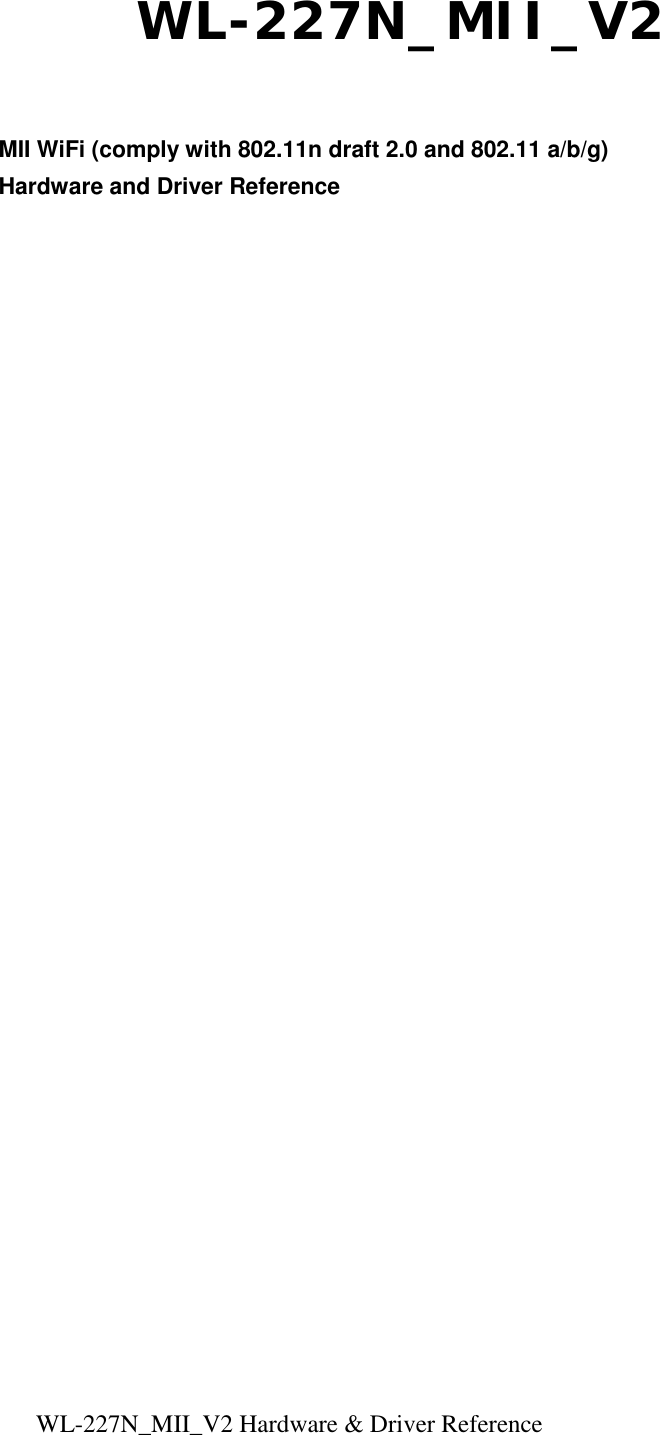
![WL-227N_MII_V2 Hardware & Driver Reference Driver installation for Linux 1. Insert USB flash disk & WL-227N NIC before booting 2. Boot Linux system and login 3. Create path [Wireless]: mkdir /etc/Wireless 4. Mount USB Hard Disk: mount /dev/sda1 /mnt 5. Copy tar file to Linux from USB Hard Disk: cp /mnt/2008_0812_RT2880_iNIC_v1.1.8.0.tar.bz2 /etc/Wireless/ 6. Decompress tar file to /etc/Wireless/, and it will generate a directory[2008_0812_RT2880_iNIC_v1.1.8.0]: tar -jxvf /etc/Wireless/2008_0812_RT2880_iNIC_v1.1.8.0.tar.bz2 7. Rename directory [2008_0812_RT2880_iNIC_v1.1.8.0] to [RT2880], in other words, the driver’s path was /etc/Wireless/RT2880 (default path in Ralink manual): mv 2008_0812_RT2880_iNIC_v1.1.8.0 RT2880 8. Now, we can complier driver (basic function): a. Enter [RT2880] directory: cd RT2880 b. Rename [module-1.1.8.0] to [module]: mv module-1.1.8.0 module c. Enter [/etc/Wireless/RT2880/module] directory: cd module d. Complier driver: make After make, it will generate five files: Module.sysmvers rt2880_iNIC.ko rt2880_iNIC.mod.c rt2880_iNIC.mod.o rt2880_iNIC.o e. Copy iNIC_sta.bin and iNIC_sta_dat to [/etc/Wireless/RT2880/] from [/etc/Wireless/RT2880/firmware/]: • Enter [/etc/Wireless/RT2880/firmware/]: cd firmware • Copy iNIC_sta.bin and iNIC_sta_dat to [/etc/Wireless/RT2880/] from [/etc/Wireless/RT2880/firmware/]: cp iNIC_sta.* ../../](https://usermanual.wiki/PEGATRON/WL227NMIIV2/User-Guide-1262965-Page-5.png)
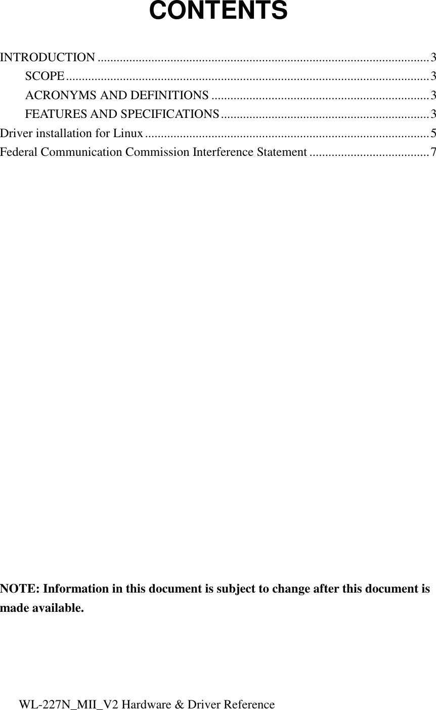
![WL-227N_MII_V2 Hardware & Driver Reference 9. Setup and bootstrap WL-227N NIC: a. Setup WL-227N NIC: insmod /etc/Wireless/RT2880/module/rt2880_iNIC.ko mode=sta • If it shows “ra0:Ralink iNIC at 0xe0cc0000(hardware address), 00:43:0c:00:00:00 (MAC address), IRQ169 (IRQ address)”, the NIC is boot strap successfully. b. Bootstrap NIC parameters: • IP address: ifconfig ra0 inet 192.168.0.11 up • If it shows the message as below, it is bootstrap successfully: Send STARTUP to RT2880 close Firmware file RACFG_CMD_BOOT_STARTUP Update MAC(0)=00:11:22:33:44:55 Or, type [ifconfig ra0] configuration. If it shows the message as below, it is bootstrap successfully, too: ra0 Link encap:Ethernet HWaddr 00:11:22:33:44:55 inet addr:192.168.0.122 Bcast:192.168.0.255 Mask:255.255.255.0 inet6 addr: fe80::211:22ff:fe33:4455/64 Scope:Link UP BROADCAST RUNNING MULTICAST MTU:1500 Metric:1 RX packets:2445 errors:0 dropped:0 overruns:0 frame:0 TX packets:2188 errors:0 dropped:0 overruns:0 carrier:0 collisions:0 txqueuelen:1000 RX bytes:2235102 (2.1 MiB) TX bytes:2236428 (2.1 MiB) Interrupt:169 c. Setup NIC connect function: Setup NIC frequency band: iwpriv ra0 set WirelessMode=9 Setup NIC connect target of AP: iwpriv ra0 set SSID=dlink type [iwconfig ra0] configuration. If it shows the message as below, it is connect successfully: ra0 RT2880 iNIC STA ESSID:”dlink” Mode:Managed Frequency:2.412 GHz Access Point: 00:1F:C6:69:BE:95 Bit Rate:54 Mb/s RTS thr:off Fragment thr:off Encryption key:off Link Quality=91/100 Signal level:-72 dBm Noise level:-71 dBm Rx invalid nwid:0 Rx invalid crypt:0 Rx invalid frag:0 Tx excessive retries:0 Invalid misc:0 Missed beacon:0](https://usermanual.wiki/PEGATRON/WL227NMIIV2/User-Guide-1262965-Page-6.png)