Pismolabs Technology P1805 Pepwave / Peplink / Pismo Wireless Product User Manual Peplink Balance
Pismo Labs Technology Limited Pepwave / Peplink / Pismo Wireless Product Peplink Balance
Contents
- 1. User Manual (1 of 4).pdf
- 2. User Manual (2 of 4).pdf
- 3. User Manual (3 of 4).pdf
- 4. User Manual (4 of 4).pdf
User Manual (4 of 4).pdf
USER MANUAL
Peplink Balance Series
http://www.peplink.com -151 / 227 - Copyright © 2014 Peplink
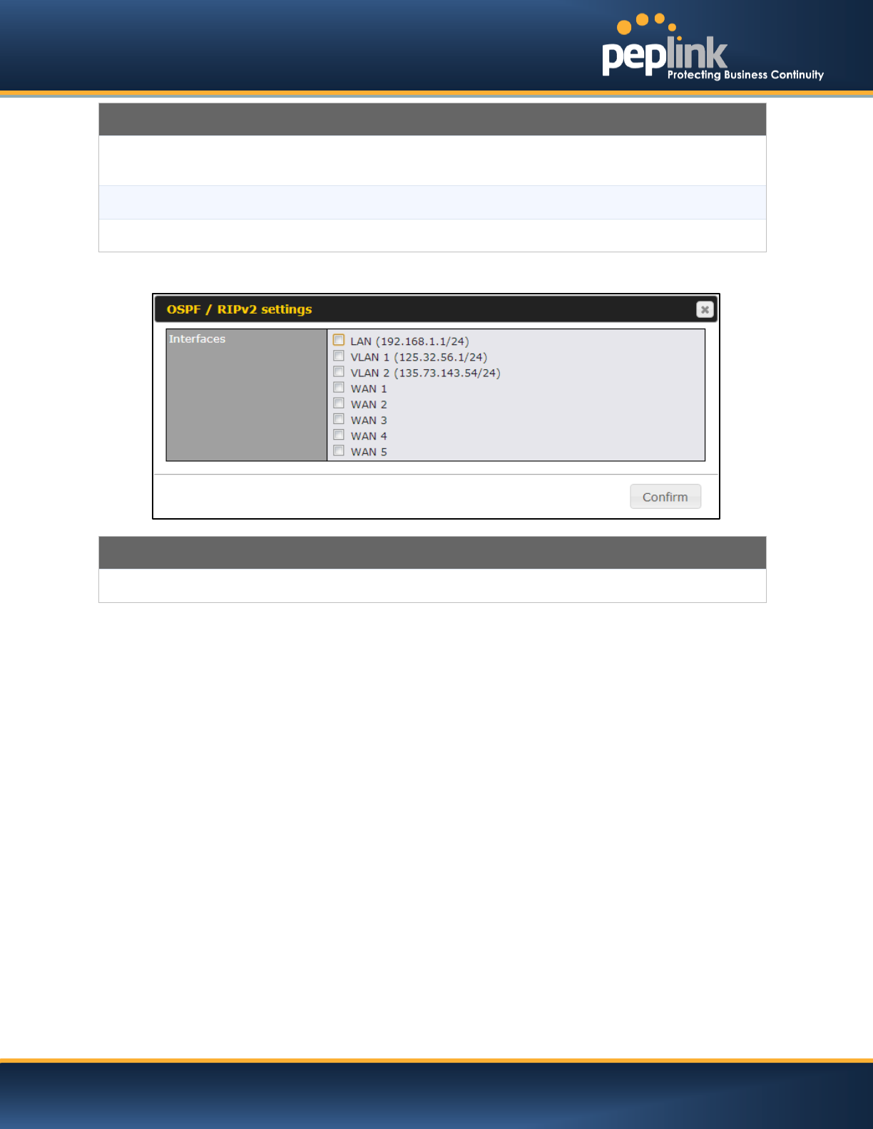
OSPFv2 / RIPv2 Settings
Area ID
Determine the name of your Area ID to apply to this group. Machines linked to this group
will send and receive related OSPFv2 packets, while unlinked machines will ignore it.
Link Type
Choose the network type that this area will use.
Interfaces
Determine which interfaces this area to use to listen to and deliver OSPFv2 packets
RIPv2 Settings
Interfaces
Determine which interfaces this group to use to listen to and deliver RIPv2 packets.
USER MANUAL
Peplink Balance Series
http://www.peplink.com -152 / 227 - Copyright © 2014 Peplink
21 Miscellaneous Settings
The miscellaneous settings include configuration for High Availability, PPTP Server, Service Forwarding,
and Service Passthrough.
21.1 High Availability
(Available on Peplink Balance 210+)
Peplink Balance supports High Availability (HA) configurations via an open standard Virtual Router
Redundancy Protocol (VRRP, RFC 3768).
In an HA configuration, two same-model Peplink Balance units (e.g. a pair of Peplink Balance 210 units,
or a pair of Peplink Balance 710 units) provide redundancy and failover in a master-slave arrangement. In
the event that the Master Unit is down, the Slave Unit becomes active.
High Availability will be disabled automatically where there is a Drop-in connection configured on a LAN
Bypass port.
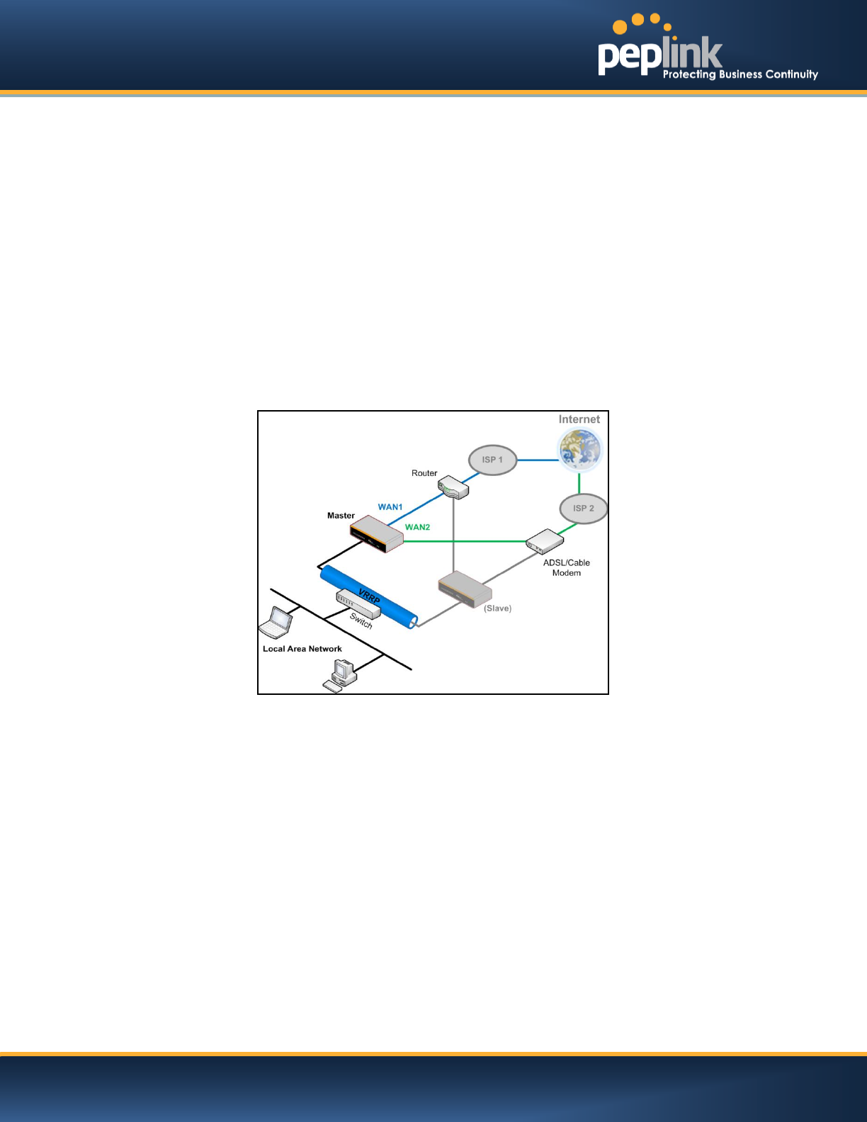
The following diagram illustrates an HA configuration with twoPeplink Balance 210 units, and two Internet
connections:
In the diagram, the WAN ports ofeach Peplink Balance unit connect to the router andto the modem.Both
Peplink Balance unitsconnect to the same LAN switch via a LAN port.
An elaboration on the technical details of the implementation, by Peplink Balance, of Virtual Router
Redundancy Protocol (VRRP, RFC 3768) is as follows:
In an HA configuration, the two Peplink Balance units communicate with each other using VRRP
over the LAN.
The two Peplink Balance units broadcast heartbeat signals to the LAN at a frequency of one
heartbeat signal per second.
In the event that no heartbeat signal from the Master Peplink Balance unit is received in 3
seconds (or longer) since the last heartbeat signal, the Slave Peplink Balance unit becomes
active.
The Slave Peplink Balance unit initiates the WAN connections, and binds to a previously
configured LAN IP address.
At a subsequent point when the Master Peplink Balance unit recovers, it will once again become
active.
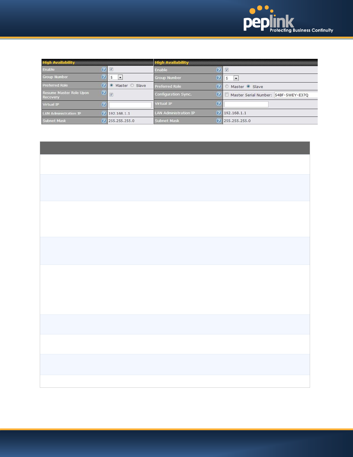
You can configure High Availability at the following location:Network>Misc. Settings > High Availability:
USER MANUAL
Peplink Balance Series
http://www.peplink.com -153 / 227 - Copyright © 2014 Peplink
Interface for Master Router
Interface for Slave Router
High Availability
Enable
Checking this box specifies that the Peplink Balance unit is part of a High Availability
configuration.
Group Number
This number identifies a pair of Peplink Balance units operating in a High Availability
configuration.The two Peplink Balance units in the pair must have the same Group Number
value.
Preferred Role
This setting specifies whether the Peplink Balance unit operates in Master or Slave mode.
Click the corresponding radio button to set the role of the unit.
One of the units in the pair must be configured as the Master and the other unit must be
configured as the Slave
Resume Master
Role Upon
Recovery
This option is displayed when Master mode is selected in Preferred Role.
If this option is enabled, once the device hasrecovered from an outage, it will take over and
resume its Master role from the slave unit.
Configuration
Sync.
This option is displayed when Slave mode is selected in Preferred Role.
If this option is enabled and the Master Serial Number entered matches with the actual
master unit's, the master unit will automatically transfer the configuration to this unit. Please
make sure the LAN IP Address and the Subnet Mask fields are set correctly in the LAN
Settings page.
You can refer to the Event Log for the configuration synchronization status.
Master Serial
Number
If the box Configuration Sync. is checked, the serial number of the Master unit is required
here for the feature to work properly.
Virtual IP
The HA pair must share the same Virtual IP. This Virtual IP and the LAN Administration IP
must be under the same network.
LAN
Administration IP
This setting specifies a LAN IP address to be used for accessing administration functionality.
This address should be unique within the LAN.
Subnet Mask
This setting specifies the subnet mask of the LAN.
USER MANUAL
Peplink Balance Series
http://www.peplink.com -154 / 227 - Copyright © 2014 Peplink
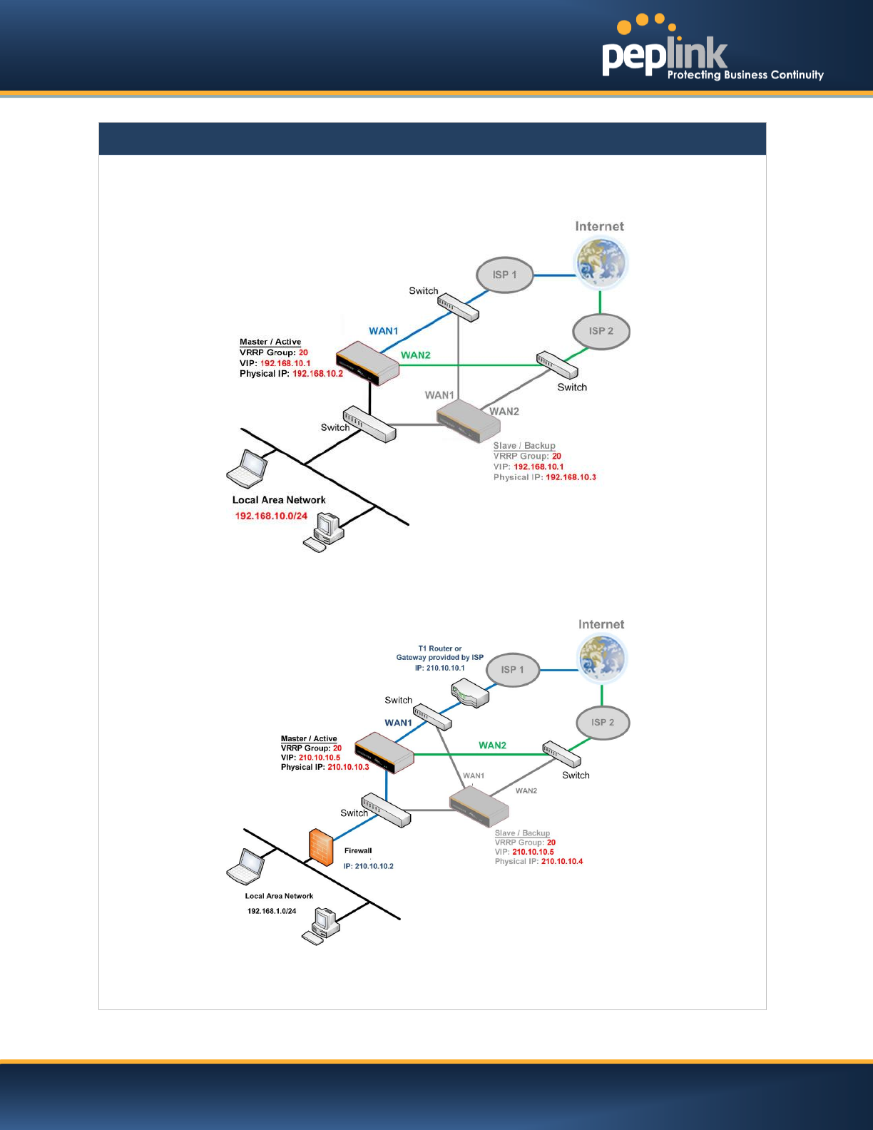
Important Note
For Balance Routers in NAT mode, the Virtual IP (VIP) should be set as the default gateway for all hosts sitting on
the LAN segment. For example, a firewall sitting behind the Balance should set its default gateway as the Virtual
IP instead of the IP of Master Balance.
In Drop-in mode, no other configuration needs to be set.
Please note that the Drop-in WAN cannot be configured as a LAN Bypass port while it is configured for High
Availability.
USER MANUAL
Peplink Balance Series
http://www.peplink.com -155 / 227 - Copyright © 2014 Peplink
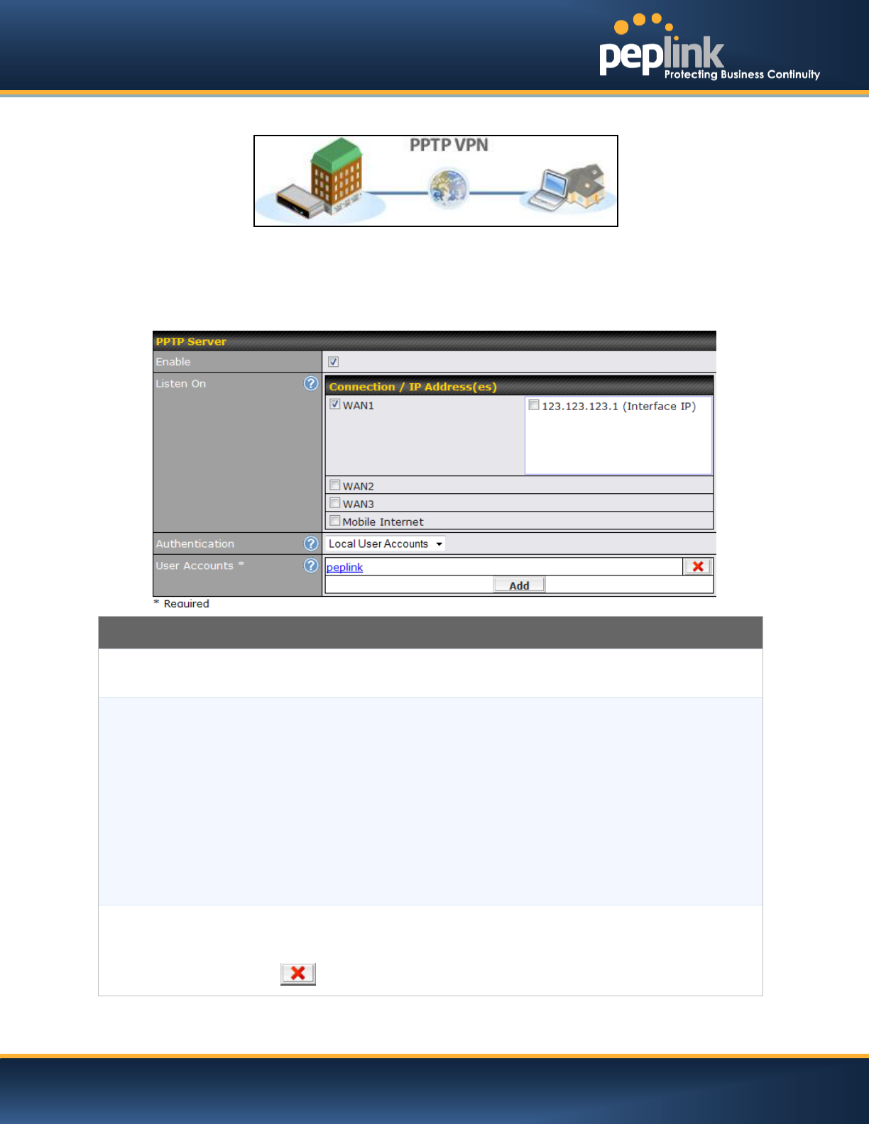
21.2 PPTP Server
Peplink Balance has a built-in PPTP Server, which enables remote computers to conveniently and
securely access the local network.
PPTP server settingsare located at: Network> Misc. Settings > PPTP Server
Simply check the box to enable the PPTP server function. All connected PPTP sessions are displayed on
the Client List at Status > Client List.Please refer to section 25.3 for details.
PPTP Server Setting
Listen On
This setting is for specifying the WAN connection(s) and IP address(es) that the PPTP
server should listen on.
Authentication
(This option is only applicable on Peplink Balance 305 and 380+.)
This setting is for specifying the user database source for PPTP authentication. Three
sources can be selected: Local User Accounts, LDAP Server, RADIUS Server.
Local User Accounts - User accounts are stored in the Peplink Balance locally. You can
add/modify/delete accounts in the User Accounts table below.
LDAP Server - Authenticate with an external LDAP server. Tested with OpenLDAP server
where passwords are NTLM hashed. Active Directory is not supported. (You can choose to
use RADIUS to authenticate with a Windows Server.)
RADIUS Server - Authenticate with an external RADIUS server. Tested with Microsoft
Windows Internet Authentication Service, and FreeRADIUS servers where passwords are
NTLM hashed or in plain text.
User Accounts
This setting allows you to define the PPTP User Accounts for authentication via Local User
Accounts. Click Add to input username and password to create an account. After adding
the user accounts, you can click on a username to edit the account password. Click the
button to delete the account in its corresponding row.
USER MANUAL
Peplink Balance Series
http://www.peplink.com -156 / 227 - Copyright © 2014 Peplink
Important Note
PPTP server will be disabled automatically if the Balance is deployed in Drop-in mode.
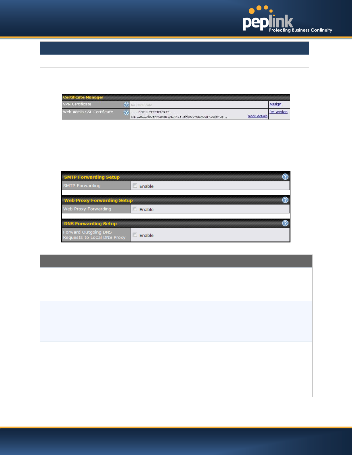
21.3 Certificate Manager
This section allows you to assign certificates for Local VPN and Web Admin SSL. The local keys will not
be transferred to another device by any means.
21.4 Service Forwarding
Service Forwarding settings are located at:Network>Misc. Settings >Service Forwarding
Service Forwarding
SMTP Forwarding
When this option is enabled, all outgoing SMTP connections destined for any host at
TCP port 25 will be intercepted. These connections will be redirected to a specified
SMTP server and port number. SMTP server settings for each WAN can be specified
after selecting Enable.
Web Proxy Forwarding
When this option is enabled, all outgoing connections destined for the proxy server
specified in Web Proxy Interception Settings will be intercepted. These connections
will be redirected to a specified web proxy server and port number. Web Proxy
Interception Settings and proxy server settings for each WAN can be specified after
selecting Enable.
DNS Forwarding
When this option is enabled, all outgoing DNS lookups will be intercepted and
redirected to the built-in DNS name server.
If any LAN device is using DNS name servers of a WAN connection, you may want to
enable this option to enhance the DNS availability without modifying the DNS server
setting of the clients. The built-in DNS name server will distribute DNS lookups to
corresponding DNS servers of all available WAN connections. In this case, DNS
service will not be interrupted even if any WAN connection is down.
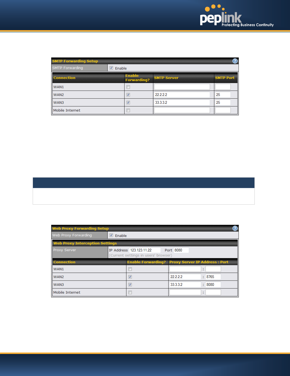
21.4.1 SMTP Forwarding
USER MANUAL
Peplink Balance Series
http://www.peplink.com -157 / 227 - Copyright © 2014 Peplink
Some ISPs require their users to send e-mails via the ISP’s SMTP server.All outgoing SMTP connections
are blocked except those connecting to the ISP’s. The Peplink Balance supports theinterception and
redirection of all outgoing SMTP connections (destined for TCP port 25) via a WAN connection to the
WAN’s corresponding SMTP server.
To enable the feature, select the Enable check box under SMTP Forwarding Setup. Check the box
Enable Forwarding for the WAN connection(s) that needs such forwarding. Under SMTP Server, enter
the ISP’s e-mail server host name or IP address and under SMTP Port, enter the TCP port number for
each WAN.
The Peplink Balance will intercept SMTP connections, choose a WAN port according to the Outbound
Policy, and then forward the connection to the SMTP server if the chosen WAN has enabled forwarding.
If the forwarding is disabled for a WAN connection, SMTP connections for the WAN will be simply be
forwarded to the connection’s original destination.
Note
If you want to route all SMTP connections only to particular WAN connection(s), you should create a custom rule
in Outbound Policy (see Section 14.1).
21.4.2 Web Proxy Forwarding
When this feature is enabled, the Peplink Balance will intercept all outgoing connections destined for the
proxy server specified in "Web Proxy Server Interception Settings". Then it will choose a WAN connection
accordingto theOutbound Policy and forward the connectionto the specified web proxy server and port
number. Redirected server settings for each WAN can be set here. If forwarding is disabled for a WAN,
then web proxy connections for thatWAN will simply be forwarded to the connection’s original destination.
USER MANUAL
Peplink Balance Series
http://www.peplink.com -158 / 227 - Copyright © 2014 Peplink
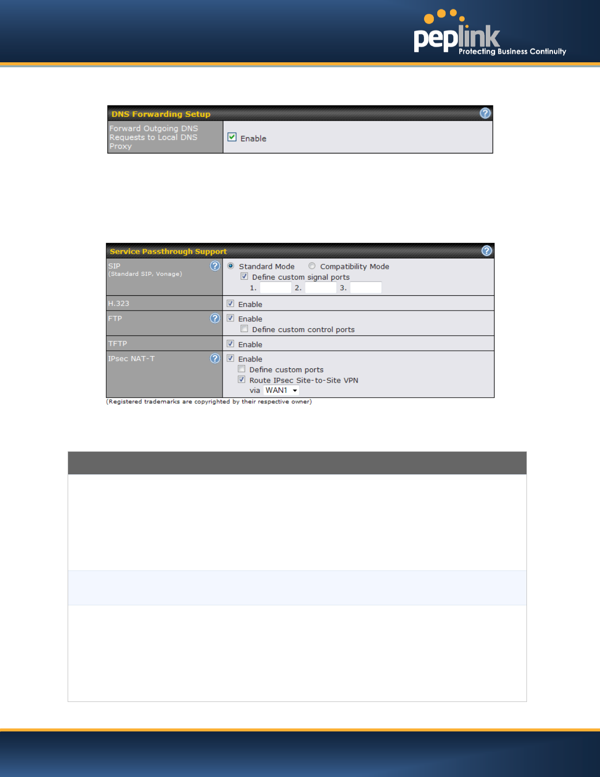
21.4.3 DNS Forwarding
When DNS Forwarding is enabled, all clients’ outgoing DNS requests will also be intercepted and
forwarded to the built-in DNS proxy server.
Service Passthrough
Service Passthrough settings can be found at:Network >Misc. Settings> Service Passthrough
Some Internet services need to be specially handled in a multi-WAN environment.The Peplink Balance
can handlethese services such that Internet applications do not notice it is behind a multi-WAN router.
Settings for Service Passthrough Support are available here.
Service Passthrough Support
SIP
Session Initiation Protocol, aka SIP, is a voice-over-IP protocol. The Peplink Balance can
act as a SIP Application Layer Gateway (ALG) which binds connections for the same SIP
session to the same WAN connection and translate IP address in the SIP packets
correctly in NAT mode. Such passthrough support is always enabled and there are two
modes for selection: Standard Mode and Compatibility Mode
If your SIP server’s signal port number is non-standard, you can check the box Define
custom signal ports and input the port numbers to the text boxes.
H.323
With this option enabled, protocols that provide audio-visual communication sessions will
be defined on any packet network and passthrough the Balance.
FTP
FTP sessions consist of two TCP connections; one for control and one for data. In multi-
WAN situation, they have to be routedto the same WAN connection. Otherwise,
problems will arise in transferring files. By default, the Peplink Balance monitors TCP
control connections on port 21 for any FTP connections and binds TCP connections of
the same FTP session to the same WAN.
If you have an FTP server listening on a port number other than 21, you can check the
box Define custom control ports and enter the port numbers to the text boxes.

USER MANUAL
Peplink Balance Series
http://www.peplink.com -159 / 227 - Copyright © 2014 Peplink
TFTP
The Peplink Balance monitors outgoing TFTP connections and routes any incoming
TFTP data packets back to the client. Select Enable if you want to enable the TFTP
Passthrough support.
IPsec NAT-T
This field is for enabling the support of IPsec NAT-T Passthrough. UDP ports 500, 4500
and 10000 are monitored by default.
You may add more custom data ports that your IPsec system usesby checking the
box Define custom ports. If the VPN contains IPsec Site-to-Site VPN traffic, you have
to check the box Route IPsecSite-to-Site VPN and choose the WAN connection to
route the traffic to.
USER MANUAL
Peplink Balance Series
http://www.peplink.com -160 / 227 - Copyright © 2014 Peplink
22 AP
The AP Controller acts as a centralized controller of Pepwave AP devices. With this feature, users will be able to
customize and manage multiple AP one a single Peplink Balance Interface.
To configure, navigate to the AP tab and the following options will be shown.
Special Note
Each Balance router can control a limited number of routers without cost. To manage more, a Full Edition license is
required. Please contact our Authorized Reseller or Peplink Sales Team to obtain more information and price
details.
22.1 AP Controller
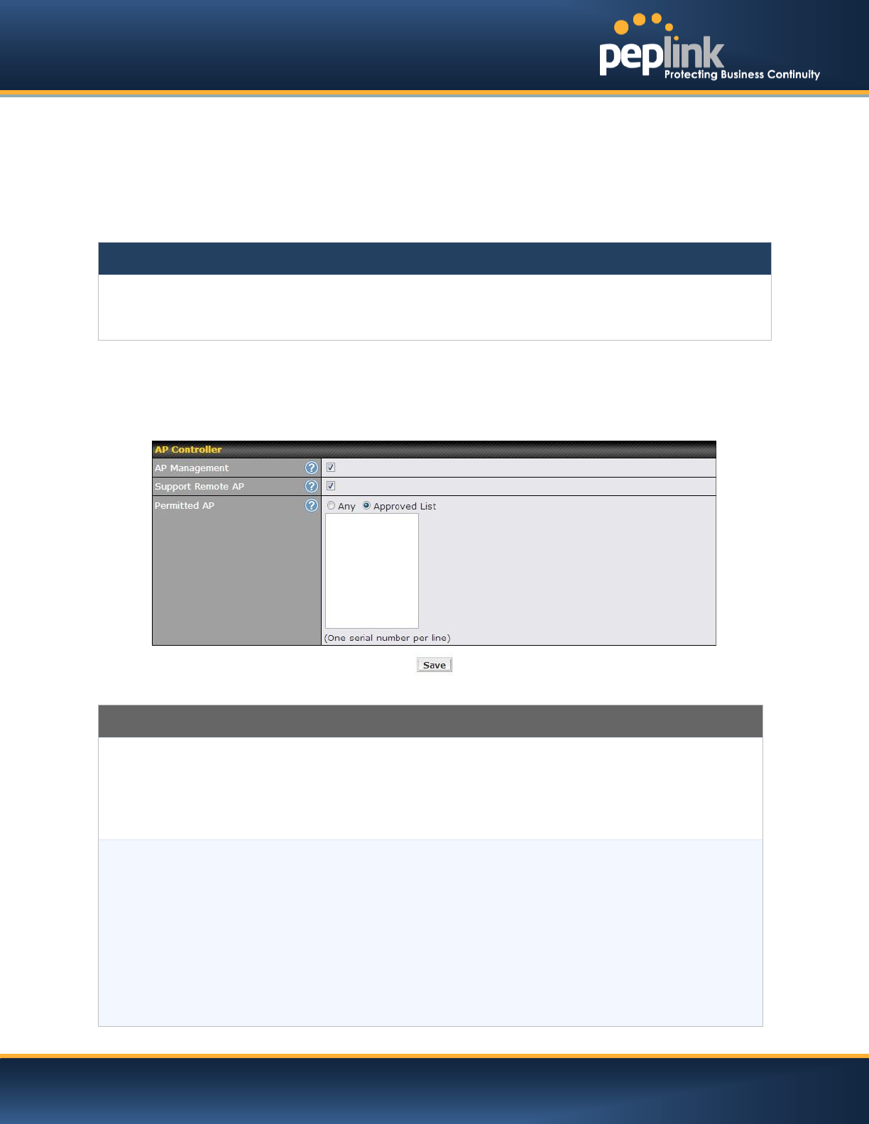
Clicking on the AP tab will default to this menu. Here, you can view basic AP management options.
Access Point Controller
AP Management
The AP Controller for managing Pepwave APs can be enabled by checking this box.
When this option is enabled, the AP Controller will wait for management connections
originating from APs over the LAN on TCP and UDP port 11753. It will also wait for
captive portal connections on TCP port 443. An extended DHCP option, CAPWAP
Access Controller addresses (field 138), will be added to the DHCP server. A local DNS
record, AP Controller, will add to the local DNS proxy.
Support Remote
AP
The AP Controller supports remote management of Pepwave APs. When this option is
enabled, the AP Controller will wait for management connections originating from remote
APs over the WAN on TCP and UDP port 11753. It will also wait for captive portal
connections on TCP port 443.
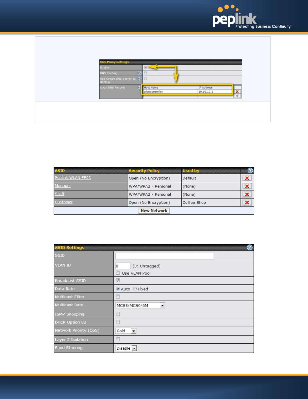
The DHCP server and/or local DNS server of the remote AP’s network should be
configured in the DNS Proxy Settings menu under Network > LAN. The procedure is as
follows:
1. Define an extended DHCP option, CAPWAP Access Controller addresses (field
138), in the DHCP server, where the values are the AP Controller's public IP
addresses; and/or
USER MANUAL
Peplink Balance Series
http://www.peplink.com -161 / 227 - Copyright © 2014 Peplink
2. Create a local DNS record for AP Controller with a value corresponding to the AP
Controller's public IP address.
Permitted AP
Access points to manage can be specifiedhere. If Any is selected, the AP Controller will
manage any AP that reports to it. If Access points listed below: is selected, only APs
with a serial number listed in the provided text box will be managed.
22.2 Wireless SSID
Wireless network settings, including the name of the network (SSID) and security policy, can be defined
and managed in this section. After defining a wireless network, users can choose the network in AP
Profiles.
Click the button New Network to create a new Network profile, or click the existing network profile to
modify its settings.
USER MANUAL
Peplink Balance Series
http://www.peplink.com -162 / 227 - Copyright © 2014 Peplink
SSID Settings
SSID
This setting specifies the SSID of the virtual AP to be scanned by Wi-Fi clients.
VLAN ID
This setting specifies the VLAN ID to be tagged on all outgoing packets
generated from this wireless network (i.e., packets that travel from the Wi-Fi
segment through the Pepwave AP One unit to the Ethernet segment via the LAN
port). The default value of this setting is 0, which means VLAN tagging is
disabled (instead of tagged with zero).
Broadcast SSID
This setting specifies whether or not Wi-Fi clients can scan the SSID of this
wireless network. Broadcast SSID is enabled by default.
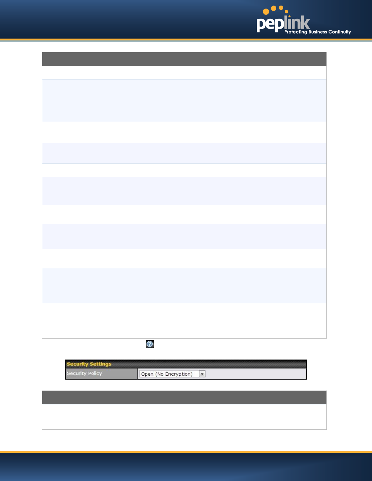
Data Rate A
Select Auto to allow the Peplink Balance to set the data rate automatically or
select Fixed and choose a rate from the displayed drop-down menu.
Multicast FilterA
This setting enables the filtering of multicast network traffic to the wireless SSID.
Multicast RateA
This setting specifies the transmit rate to be used for sending multicast network
traffic. The selected Protocol and Channel Bonding settings will affect the rate
options and values available here.
IGMP Snooping A
To allow the Peplink Balance to listen to Internet Group Management Protocol
(IGMP) network traffic, select this option.
DHCP Option 82 A
If you use a distributed DHCP server/relay environment, you can enable this
option to provide additional information on the manner in which clients are
physically connected to the network.
Network Priority (QoS) A
Select from Gold, Silver, and Bronze to control the QoS priority of this wireless
network’s traffic.
Layer 2 Isolation A
Layer 2 refers to the second layer in the ISO Open System Interconnect model.
When this option is enabled, clients on the same VLAN, SSID, or subnet are
isolated to that VLAN, SSID, or subnet, which can enhance security. Traffic is
passed to upper communication layer(s). By default, the setting is disabled.
Band Steering A
Band steering allows the Peplink Balance to steer AP clients from the 2.4 GHz
band to the 5GHz band for better usage of bandwidth. To make steering
mandatory, select Enforce. To cause the Peplink Balance to preferentially
choose steering, select Prefer. The default for this setting is Disable.
A - Advanced feature, please click the button on the top right hand corner to activate.
Security Settings
Security Policy
This setting configures the wireless authentication and encryption methods. Available
options areOpen (No Encryption), WPA/WPA2 - Personal, WPA/WPA2 -
Enterpriseand Static WEP.
USER MANUAL
Peplink Balance Series
http://www.peplink.com -163 / 227 - Copyright © 2014 Peplink
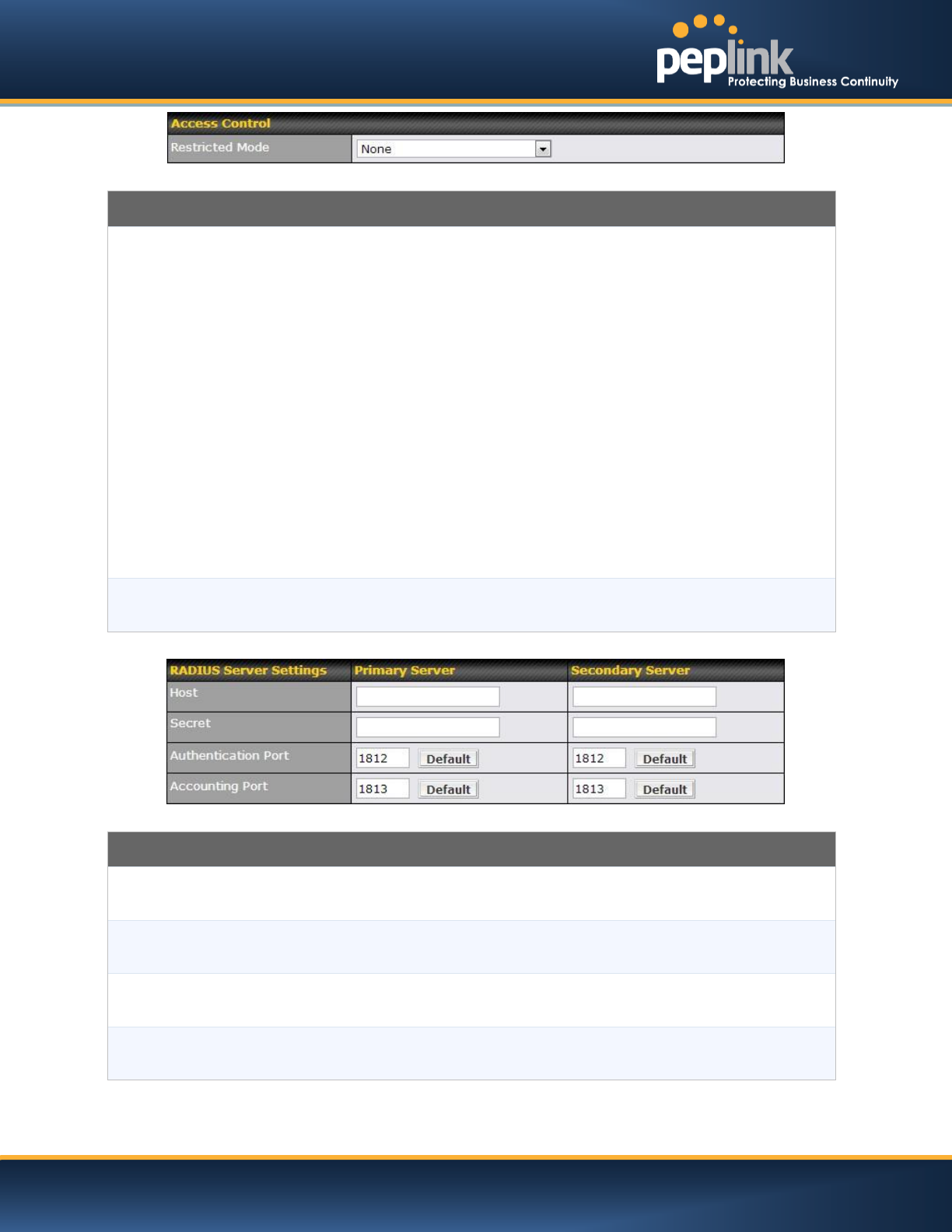
Access Control
Restricted Mode
The settings allow administrator to control access using Mac address filtering. Available
options areNone, Deny all except listed, Accept all except listed, and RADIUS MAC
Authentication.
When WPA/WPA2 - Enterprise is configured, RADIUS-based 802.1 x authentication is
enabled. Under this configuration, the Shared Key option should be disabled. When using
this method, select the appropriate version using the V1/V2 controls. The security level of this
method is known to be very high.
When WPA/WPA2- Personal is configured, a Shared Key is used for data encryption and
authentication. When using this configuration, the Shared Key option should be enabled.
Key length must be between eight and 63 characters (inclusive). The security level of this
method is known to be high.
The configuration of static WEP parameters enables pre-shared WEP key encryption.
Authentication is not supported by this method. The security level of this method is known to
be weak.
MAC Address
List
Connection coming from the MAC Addresses in this list will be either denied or accepted
based the option selected in the previous field.
RADIUS Server Settings
Host
Enter the IP address of the primary RADIUS server and, if applicable, the secondary RADIUS
server.
Secret
Enter the RADIUS shared secret for the primary server and, if applicable, the secondary
RADIUS server.
Authentication
Port
In field, enter the UDP authentication port(s) used by your RADIUS server(s) or click the
Default button to enter 1812.
Accounting Port
In field, enter the UDP accounting port(s) used by your RADIUS server(s) or click the Default
button to enter 1813.
USER MANUAL
Peplink Balance Series
http://www.peplink.com -164 / 227 - Copyright © 2014 Peplink
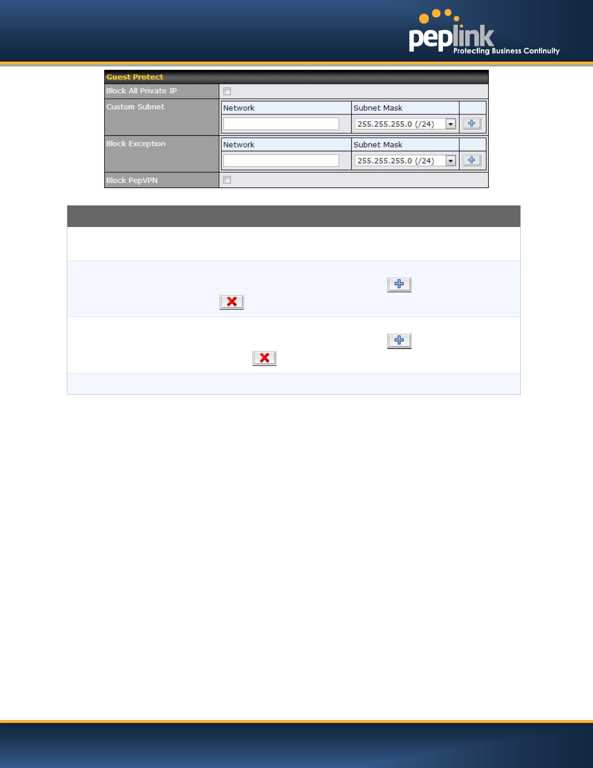
Guest Protect
Block All Private
IP
Check this box to deny all connection attempts by private IP addresses.
Custom Subnet
To create a custom subnet for guest access, enter the IP address and choose a subnet mask
from the drop-down menu. To add the new subnet, click the button. To delete a custom
subnet, click the button.
Block Exception
To block access from a particular subnet, enter the IP address and choose a subnet mask
from the drop-down menu. To add the new subnet, click the button. To delete a
blocked subnet, click the button.
Block PepVPN
To block PepVPN access, check this box.
USER MANUAL
Peplink Balance Series
http://www.peplink.com -165 / 227 - Copyright © 2014 Peplink
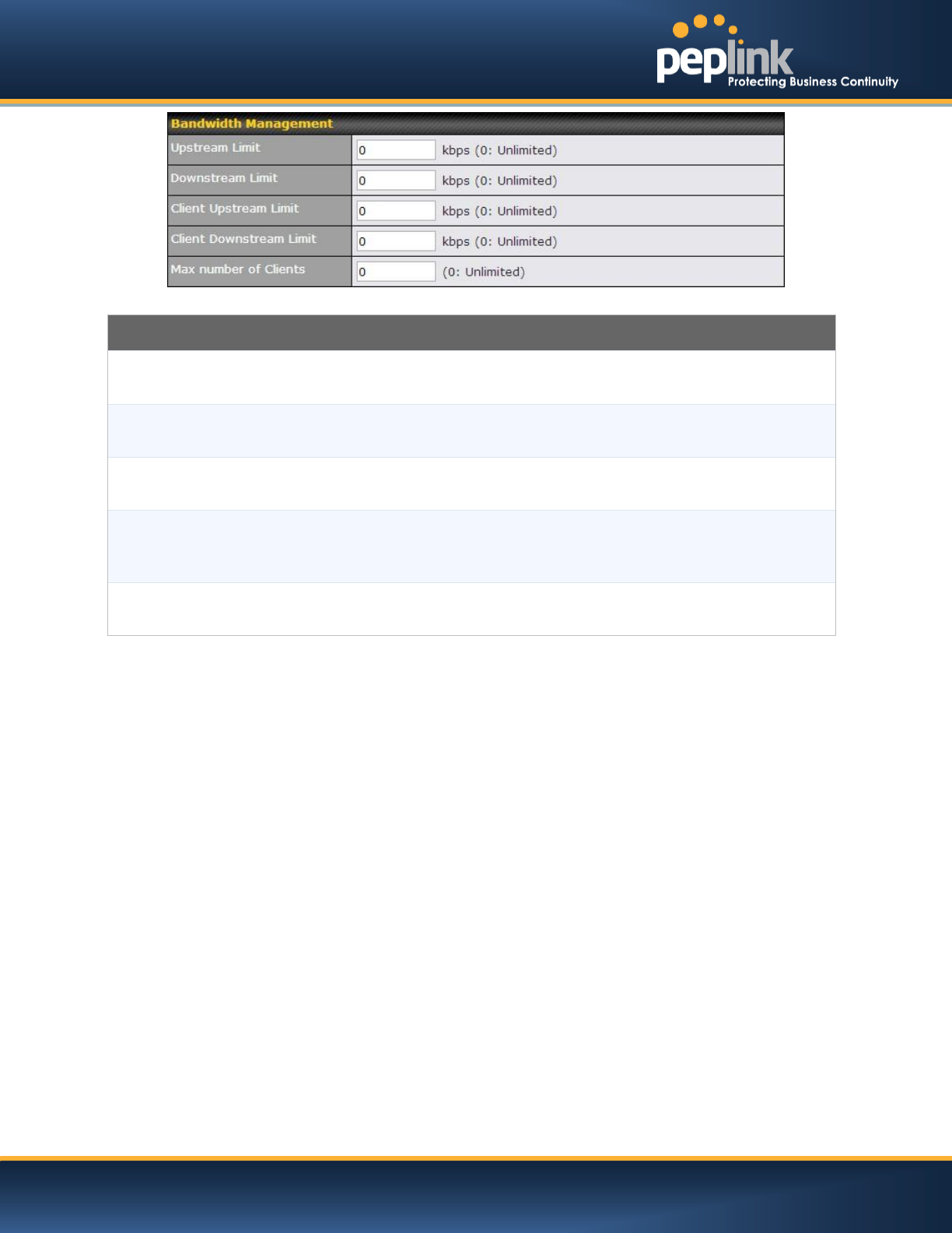
Bandwidth Management
Upstream Limit
Enter a value in kpbs to limit the wireless network’s upstream bandwidth. Enter 0 to allow
unlimited upstream bandwidth.
Downstream
Limit
Enter a value in kpbs to limit the wireless network’s downstream bandwidth. Enter 0 to allow
unlimited downstream bandwidth.
Client Upstream
Limit
Enter a value in kpbs to limit connected clients’ upstream bandwidth. Enter 0 to allow
unlimited upstream bandwidth.
Client
Downstream
Limit
Enter a value in kpbs to limit connected clients’ downstream bandwidth. Enter 0 to allow
unlimited downstream bandwidth.
Max Number of
Clients
Enter the maximum number of clients that can simultaneously connect to the wireless network
or enter 0 to allow an unlimited number of connections.
USER MANUAL
Peplink Balance Series
http://www.peplink.com -166 / 227 - Copyright © 2014 Peplink
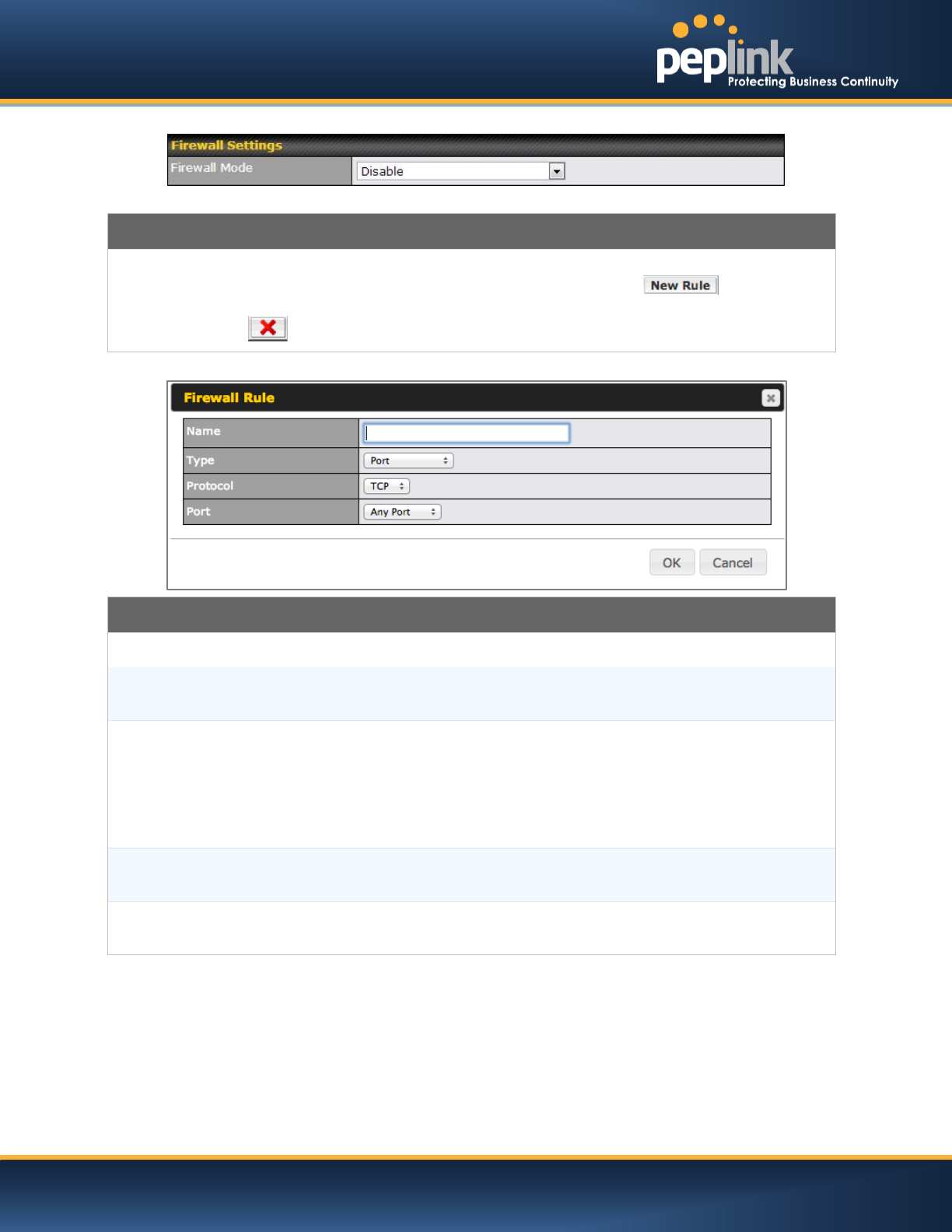
Firewall Settings
Firewall Mode
Choose Flexible – Allow all except… or Lockdown – Block all except… to turn on the
firewall, then create rules for the firewall exceptions by click the button. See the
discussion below for details on creating a firewall rule. To delete a rule, click the associated
button. To turn off the firewall, select Disable.
Firewall Rule
Name
Enter a descriptive name for the firewall rule in this field.
Type
Choose Port, Domain, IP Address, or MAC Address to allow or deny traffic from any of
those identifiers. Depending on the option chosen, the following fields will vary.
Protocol / Port
Choose TCP or UDP from the Protocol drop-down menu to allow or deny traffic using either
of those protocols. From the Port drop-down menu, choose Any Port to allow or deny TCP or
UDP traffic on any port. Choose Single Port and then enter a port number in the provided
field to allow or block TCP or UDP traffic from that port only. You can also choose Port
Range and enter a range of ports in the provided fields to allow or deny TCP or UDP traffic
from the specified port range.
IP Address /
Subnet Mask
If you have chosen IP Address as your firewall rule type, enter the IP address and subnet
mask identifying the subnet to allow or deny.
MAC Address
If you have chosen MAC Address as your firewall rule type, enter the MAC address
identifying the machine to allow or deny.
USER MANUAL
Peplink Balance Series
http://www.peplink.com -167 / 227 - Copyright © 2014 Peplink
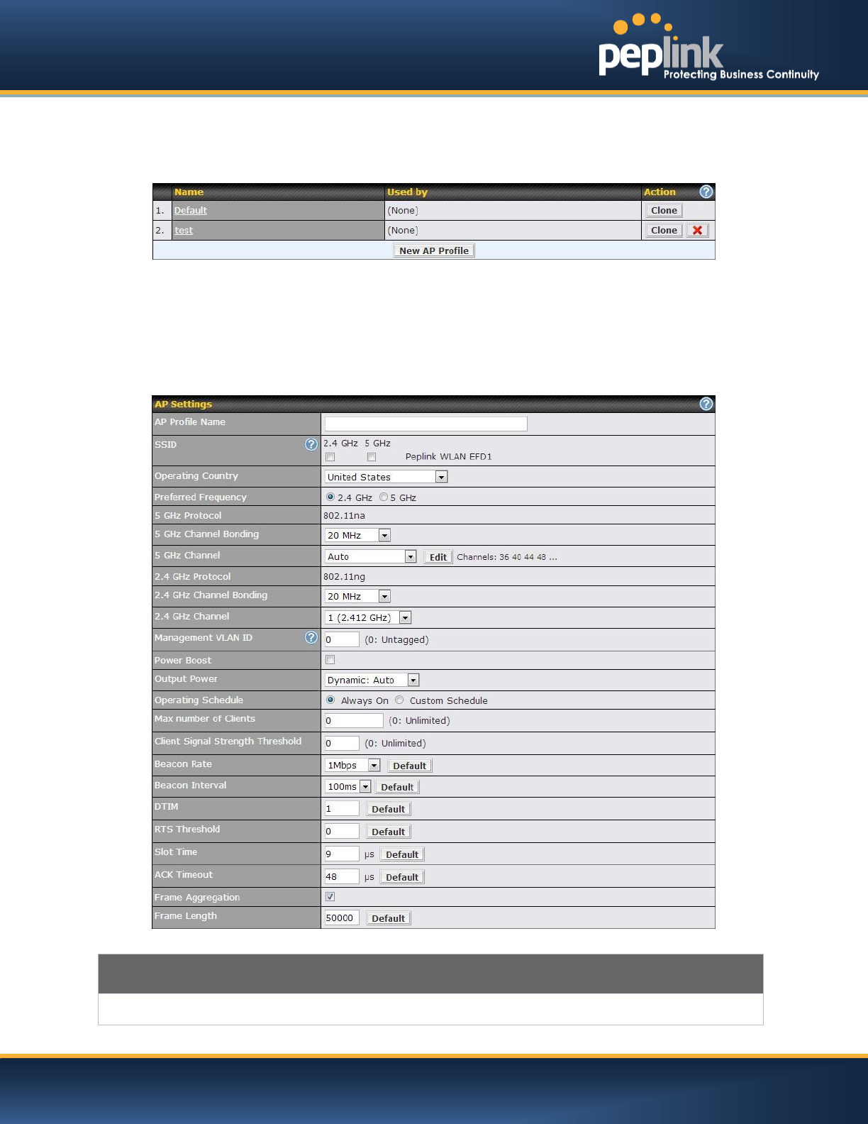
22.3 Profiles
AP profiles assigned to each Pepwave AP device can be configured at AP > Profiles
Each AP is associated with one AP Profile. By default, all devices are associated with the first (Default)
profile. The Default profile cannot be removed.
You can define an AP profile by clicking the New AP Profile button. Click the Clone button of an existing
profile to create a new profile based on it. To change the settings of an existing profile, click the profile
name and the following screen will be shown.
AP Settings
AP Profile Name
This field specifies the name of this AP Profile.

USER MANUAL
Peplink Balance Series
http://www.peplink.com -168 / 227 - Copyright © 2014 Peplink
SSID
These buttons specify which wireless networks will use this AP Profile. You can also
select the frequencies at which each network will transmit. Please note that the Peplink
Balance does not detect weather the AP is capable of transmitting at both frequencies.
Instructions to transmit at unsupported frequencies will be ignored by the AP.
Operating Country
This drop-down menu specifies the national / regional regulations which the AP should
follow.
If a North American region is selected, RF channels 1 to 11 will be available and
the maximum transmission power will be 26 dBm (400 mW).
If European region is selected, RF channels 1 to 13 will be available. The
maximum transmission power will be 20 dBm (100 mW).
NOTE: Users are required to choose an option suitable to local laws and regulations.
Per FCC regulation, the country selection is not available on all models marketed in US.
All US models are fixed to US channel only.
Preferred Frequency
These buttons determine the frequency at which access points will attempt to broadcast.
This feature will only work for AP that can transmit at both 5.4GHz and 5GHz
frequencies,
Protocol
(5GHz, 2.4 GHz)
This section displays the wireless protocols which your AP are using.
Channel Bonding
(5GHz, 2.4 GHz)
This drop-down menu is only available for 802.11bgn or 802.11n protocols only.
There are three options: 20 MHz, 20/40 MHz and 40 MHz
With this feature enabled, it allows the Wi-Fi system to use two channels at once. Using
two channels improves the performance of the Wi-Fi connection
Channel
(5GHz, 2.4 GHz)
This drop-down menu selects the 802.11 channel to be utilized. Available options are
from 1 to 11, and from 1 to 13 for the country setting of North America region and Europe
region, respectively. (Channel 14 is only available when the country is selected as Japan
with protocol 802.11b.)
If Auto is set, the system would perform channel scanning based on the scheduled time
set and choose the most suitable channel automatically.
Management VLAN
ID
This field specifies the VLAN ID to tag to management traffic, such as AP to AP-
controller communication traffic. The value is zero by default, meaning that no VLAN
tagging will be applied. NOTE: Change this value with caution as alterations may result
in loss of connection to the AP controller.
Power BoostA
With this option enabled, the AP under this profile will transmit using additional power.
Please note that using this option with several AP in close proximity will lead to increased
interference.
Output PowerA
This drop-down menu determines the power at which the AP under this profile will
broadcast. When fixed settings are selected, the AP will broadcast at the specified power
level regardless of context. When Dynamic settings are selected, the AP will adjust its
power level based on its surrounding AP in order to maximize performance.
The Dynamic: Auto setting will set the AP to do this automatically. Otherwise, the
Dynamic: Manual setting will set the AP to dynamically adjust only of instructed to do
so. If you have set Dynamic:Manual, you can go to AP > Toolbox > Auto Power Adj. to
give your AP further instructions.
USER MANUAL
Peplink Balance Series
http://www.peplink.com -169 / 227 - Copyright © 2014 Peplink
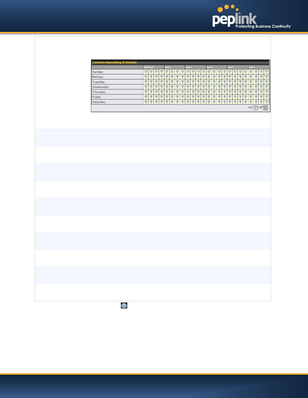
Operating ScheduleA
These buttons determine the time period at which the AP under this profile will be
activated. Clicking the Custom Schedule option will open the following diagram:
Click the desired time periods to toggle the activation state of AP under this profile.
Max number of
ClientsA
This field determines the maximum clients that can be connected to AP under this profile.
Client Signal
Strength ThresholdA
This field determines that maximum signal strength each individual client will receive.
The measuring unit is Megawatts.
Beacon RateA
This drop-down menu provides the option to send beacon in different transmit bit rate
and the bit rates are: 1Mbps, 2Mbps, 5.5Mbps, 6Mbps, 11Mbps.
Beacon IntervalA
This drop-down menu provides the option to set the time between each beacon send.
Available options are: 100ms, 250ms and 500ms.
DTIMA
This field provides the option to set the frequency for beacon to include Delivery Traffic
Indication Message, DTIM. The interval unit is measured in milliseconds.
RTS ThresholdA
This field provides the option to set the minimum packet size for the unit to send an RTS
using the RTS/CTS handshake. Setting zero would disable this feature.
Slot TimeA
This field provides the option to modify the unit wait time before it transmits. The default
value is 9μs.
ACK TimeoutA
This field provides the option to set the wait time to receive acknowledgement packet
before doing retransmission. The default value is 48μs.
Frame AggregationA
With this feature enabled, throughput will be increased by sending two or more data
frames in a single transmission.
Frame Length
This field is only available when Frame Aggregation is enabled. It specifies the frame
length for frame aggregation. By default, it is set as 50000.
A - Advanced feature, please click the button on the top right hand corner to activate.
USER MANUAL
Peplink Balance Series
http://www.peplink.com -170 / 227 - Copyright © 2014 Peplink
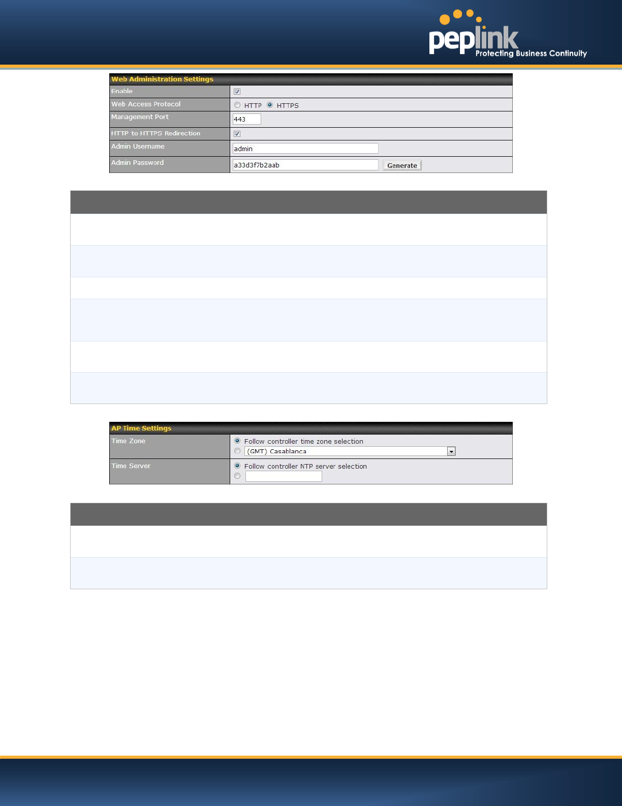
Web Administration Settings
Enable
Check the box to allow Peplink Balance to manage the web admin access information of
the AP.
Web Access Protocol
Thesebuttonsspecify the web access protocol used for accessing the web admin of AP.
The two available options are HTTP and HTTPS.
Management Port
This field specifies the management port used for accessing the device.
HTTP to HTTPS
Redirection
This option will be available if you have chosen HTTPS as the Web Access Protocol.
With this enabled, any HTTP access to the web admin will be redirect to HTTPS
automatically.
Admin User Name
This field specifies the administrator username of the web admin. It is set as admin by
default.
Admin Password
This field allows you to specify a new administrator password. You may also click the
Generate button and let the system generate a random password automatically.
AP Time Settings
Time Zone
Check the box to allow Peplink Balance to manage the web admin access information of
the AP.
Time Server
Thesebuttonsspecify the web access protocol used for accessing the web admin of AP.
The two available options are HTTP and HTTPS.
USER MANUAL
Peplink Balance Series
http://www.peplink.com -171 / 227 - Copyright © 2014 Peplink
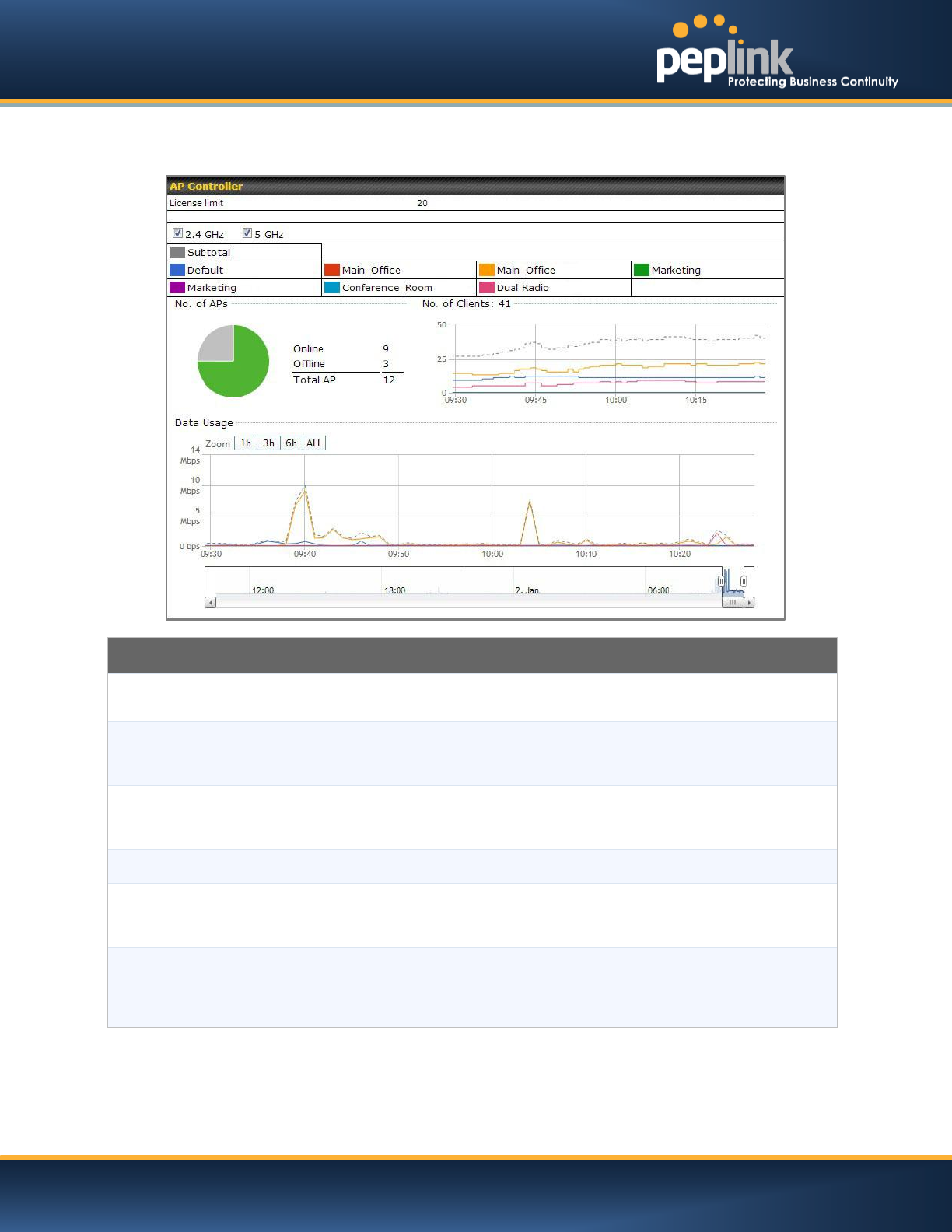
22.4 Info
A comprehensive overview of your AP can be accessed by navigating to AP > Info.
AP Controller
License Limit
This field displays the maximum number of AP your Balance router can control. You can
purchase licenses to increase the number of AP you could manage.
Frequency
Underneath, there are two check boxes labeled 2.4 Ghz and 5 Ghz. Clicking either box
will toggle the display of information for that frequency.By default, the graphs display the
number of clients and data usage for both 2.4GHz and 5 GHz frequencies.
SSID
The colored boxes indicate the SSID to display information for. Clicking any colored box
will toggle the display of information for that SSID. By default, all the graphs show
information for all SSID.
No. of APs
This pie chart and table indicates how many AP are online and how many are offline.
No.of Clients
This graph displays the number of clients connected to each network at any given time.
Mouse over any line on the graph to see how many clients connected to a specific SSID
for that point in time.
Data Usage
This graph enables you to see the data usage of any SSID for any given time period.
Mouse over any line on the graph to see the data usage by each SSID for that point in
time. Use the buttons next to Zoom to select the time scale you wish to view. In addition,
you could use the sliders at the bottom to further refine your timescale.
USER MANUAL
Peplink Balance Series
http://www.peplink.com -172 / 227 - Copyright © 2014 Peplink
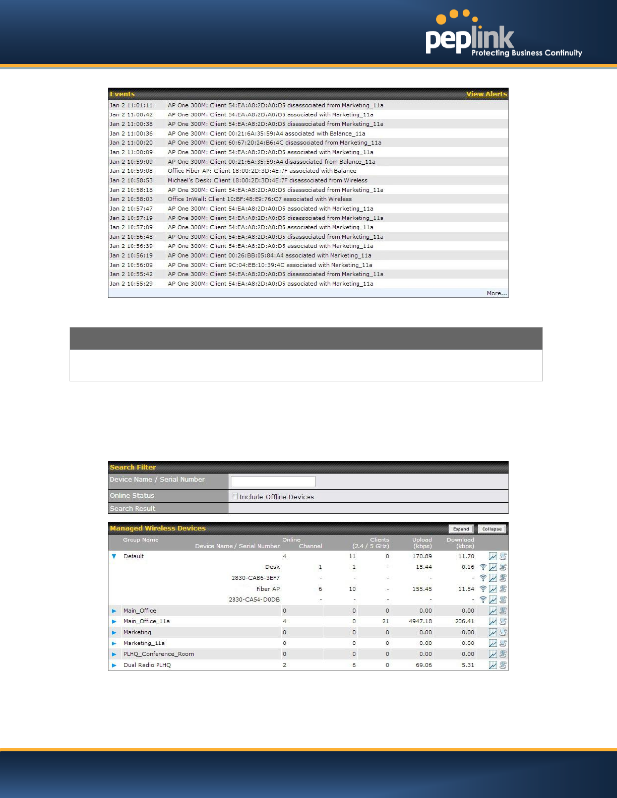
Events
This event log displays all activity on your AP network, down to the client level. Click View Alerts to see only alerts,
and click the More… link for additional records.
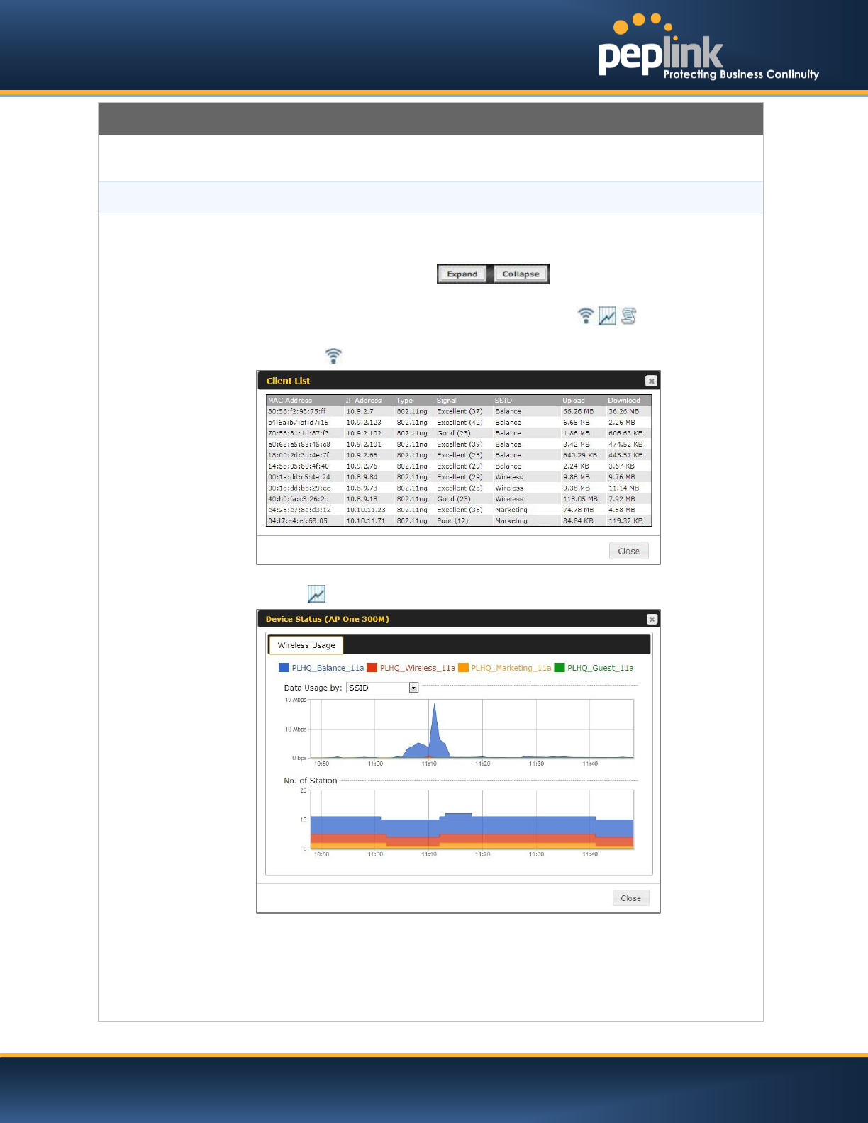
22.5 Usage
A detailed breakdown of data usage for each AP is available onAP >Status. The information is organized
by device groups as defined in section 22.3
USER MANUAL
Peplink Balance Series
http://www.peplink.com -173 / 227 - Copyright © 2014 Peplink
Usage
Device Name/Serial
Number
This field enables you to quickly find your device if you know its name or serial number.
Fill in the field to begin searching. Partial names and serial numbers are supported.
Online Status
This button toggles weather your search will include offline devices.
Managed Wireless
Devices
This table shows the detailed information on each AP, including: channel, number of
clients, upload traffic, and download traffic.Click the blue arrows on the left of the table to
expand and collapse information on each device group. You could also expand and
collapse all groups by using the buttons.
On the right of the table, you will see the following icons:
Clicking the icon, and a usage table of each client will appear:
Click the icon, and a graph displaying usage will appear:
Click any point in the graphs to display detailed usage and client information for that
device, using that SSID, at that point in time.On the Data Usage by menu, you could
choose to display the information by SSID or by AP Send/Receiverate.
USER MANUAL
Peplink Balance Series
http://www.peplink.com -174 / 227 - Copyright © 2014 Peplink
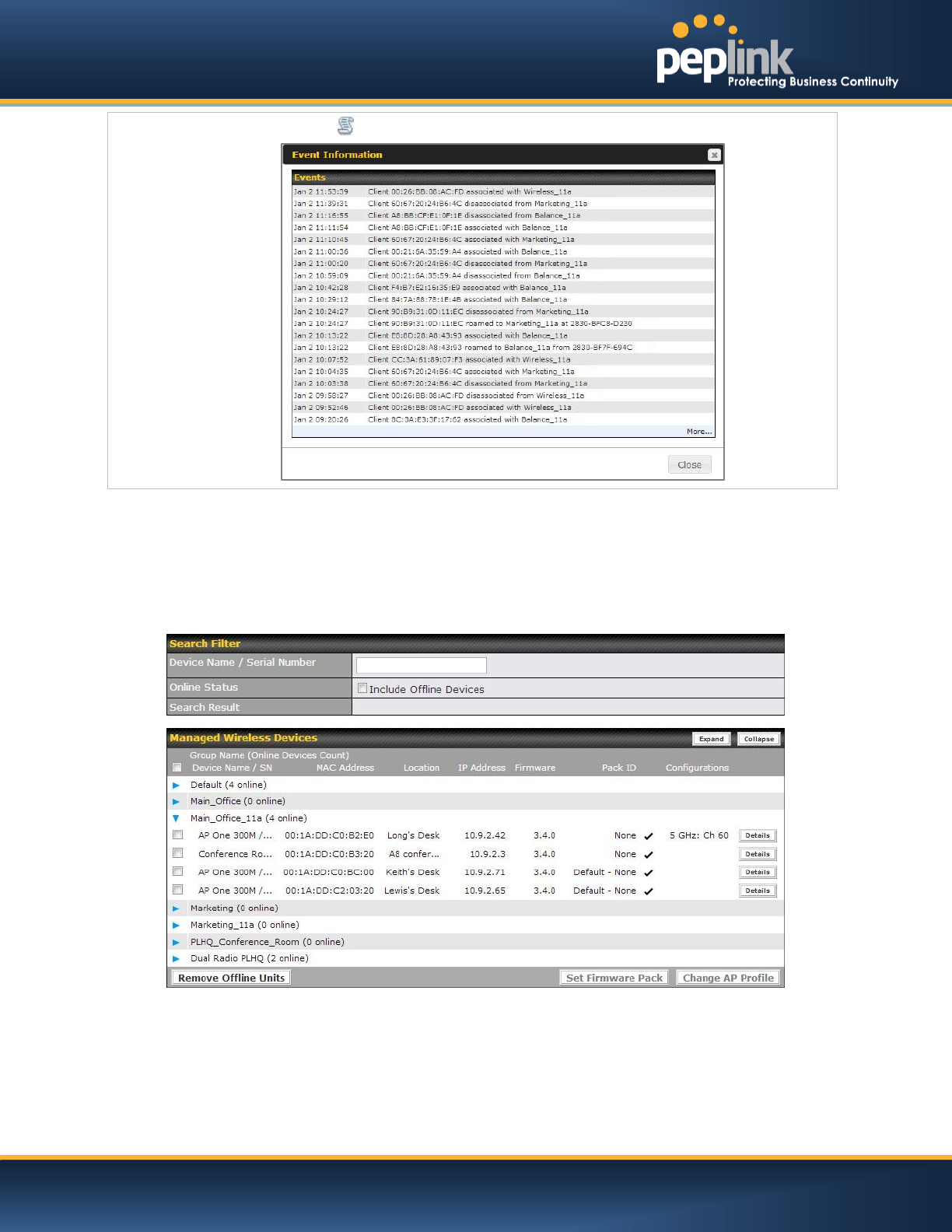
Click the icon to view a detailed event log for that particular device:
22.6 AP Status
A detailed breakdown of the status of each device is available on AP >Status. The information is
organized by device groups as defined in section 22.3
USER MANUAL
Peplink Balance Series
http://www.peplink.com -175 / 227 - Copyright © 2014 Peplink
AP Status
Device Name/Serial
Number
This field enables you to quickly find your device if you know its name or serial number.
Fill in the field to begin searching. Partial names and serial numbers are supported.
Online Status
This button toggles weather your search will include offline devices.
Managed Wireless
Devices
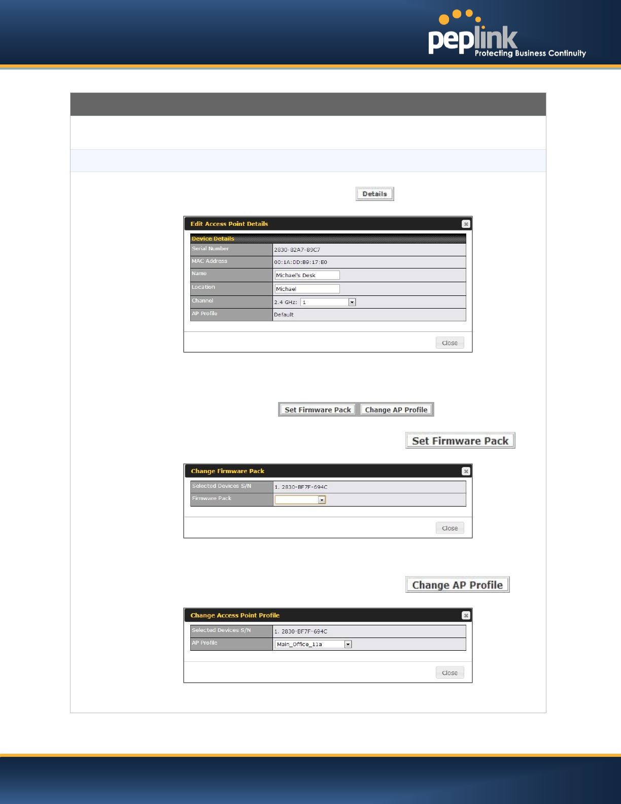
This table displays the MAC address, IP Address, firmware version, and specific
configurations of each device. Clicking the button of each device will result in
the following menu:
Here, you can edit the name and location of your AP. You can also choose the channel
to will transmit from.
You can also batch configure devices on this table by selecting the items you wish to
configure, then clicking .
After selecting your devices you wish to configure, click to
reach the following menu:
Select the pull-down menu to choose a firmware pack for the devices that you have
selected.
After selecting your devices you wish to configure, click to
reach the following menu:
Select the pull-down menu to choose an AP profile for the devices that you have
selected.
USER MANUAL
Peplink Balance Series
http://www.peplink.com -176 / 227 - Copyright © 2014 Peplink
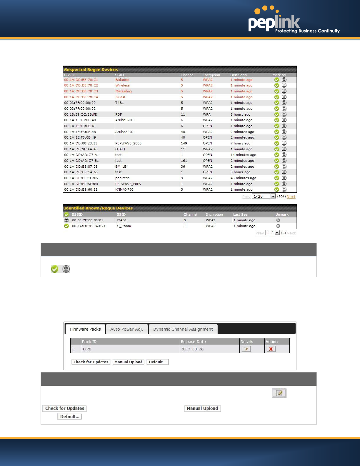
22.7 Rogue AP
A listing of suspected Rogue devicescan be accessed by navigating to AP >Rogue AP.
Suspected Rogue Devices
Hovering over the device MAC address will result in a popup with information on how this device was detected. Click
the icons and the device will be moved to the bottom table of identified devices.
22.8 Toolbox
Additional tools for managing firmware packs, power adjustment, and channel assignment can be found
under AP >Toolbox.
Firmware Packs
This is the first menu that will appear. Here, you can manage the firmware of your AP. Clicking on will result
in information regarding each firmware pack. To receive new firmware packs, you can either press
to download new packs or you can press to manually upload a firmware pack.
Press to define which firmware pack is default.
USER MANUAL
Peplink Balance Series
http://www.peplink.com -177 / 227 - Copyright © 2014 Peplink
23 System Settings
23.1 Admin Security
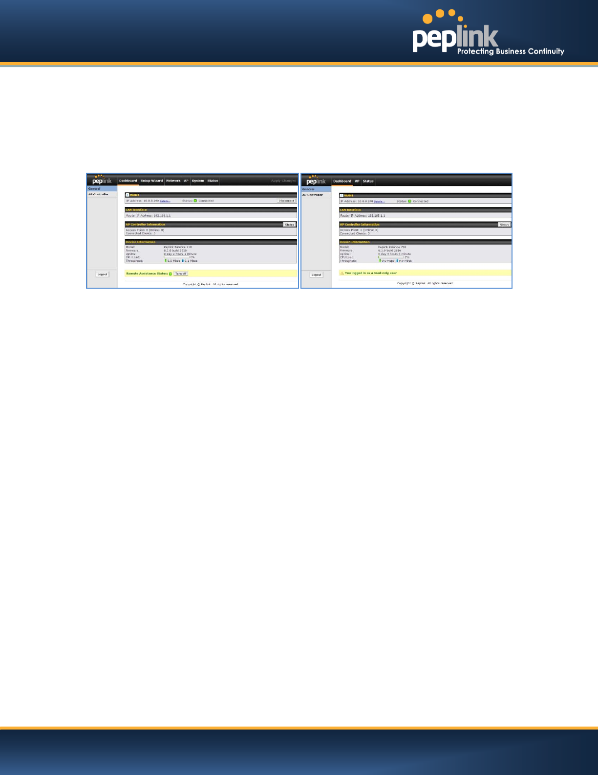
There are two types of user accounts available for accessing the Web Admin:admin and user.They
represent two user levels: the admin level has full administration access, the user level is read-only. The
user level can only access the device's status information;itcannot make any changes on the device.
A web login session will be logged out automatically when it has been idle longer than the Web Session
Timeout.Before the session expires, you may click the Logout button in the Web Admin to exit the
session
0 hours 0 minutes signifies an unlimited session time. This setting should be used only in
specialsituations, as it will lower the system security level if users do not logout before closing the browser.
Default: 4 hours 0 minutes.
For security reason, after logging in to the Web Admin Interface for the first time, it is recommended to
change the administrator password.
Configuring the administration interface to be accessible only from the LAN can further improve system
security.
Administrative Settings configuration is located at:System>Admin Security
Admin Account UI
User Account UI
USER MANUAL
Peplink Balance Series
http://www.peplink.com -178 / 227 - Copyright © 2014 Peplink
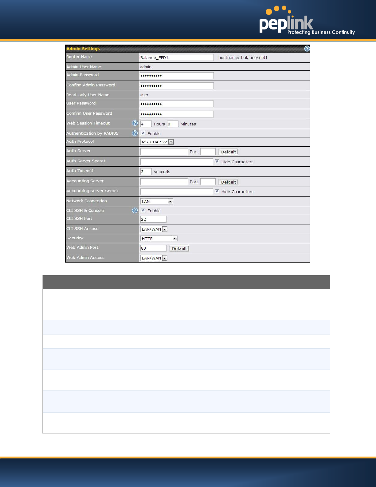
Admin Settings
Router Name
This field allows you to define a name for this Peplink Balance unit.
By default, the Router Name is set as Balance_XXXX, where XXXX refers to the last 4
digits of the serial number of that balance unit.
Admin User Name
It is set as admin by default and is not customizable.
Admin Password
This field allows you to specify a new administrator password.
Confirm Admin
Password
This field allows you to verify and confirm the new administrator password.
Read-only User
Name
It is set as user by default and is not customizable.
User Password
This field allows you to specify a new user password. Once the user password is set, the
feature of read-only user will be enabled.
Confirm User
Password
This field allows you to verify and confirm the new user password.

USER MANUAL
Peplink Balance Series
http://www.peplink.com -179 / 227 - Copyright © 2014 Peplink
Web Session
Timeout
This field specifies the number of hours and minutes that a web session can remain idle
before the Balance terminatesits access to the Web Admin Interface.
By default, it is set to4 hours.
Authentication by
RADIUS
With this box is checked,the Web Admin will authenticate using an external RADIUS server.
Authenticated users are treated as either "admin" with full read-write permission or “user”
with read-only access.Local "admin" and "user" accounts will be disabled. When the device
is not able to communicate with the external RADIUS server, local accounts will be enabled
again for emergency access.
Additional authentication options will be available once this box is checked.
Auth Protocol
This specifies the authentication protocol used. Available options are MS-CHAP v2 and
PAP.
Auth Server
This specifies the access address of the external RADIUS server.
Auth Server
Secret
This field is meant for the secret key for accessing the RADIUS server.
Auth Timeout
This option specifies the time value for authentication timeout.
Accounting Server
This specifies the access address of the external Accounting server.
Accounting Server
Secret
This field is meant for the secret key for accessing the Accounting server.
Network
Connection
This option is for specifying the network connection to be used for authentication. Users can
choose from LAN, WAN and VPN connections.
CLI SSH &
Console
The CLI (Command Line Interface) can be accessed via SSH. It can also be accessed from
the serial console port for Peplink Balance 305, 380, 580, 710, 1350 and 2500. This field
enables CLI support.
For additional information regarding CLI, please refer to section 22.5 of this manual
CLI SSH Port
This field determines the port on which clients can access CLI SSH
CLI SSH Access
This menu allows you to choose between granting access to LAN and WAN clients, or to
LAN clients only.
Security
This option is for specifying the protocol(s) through which the Web Admin Interface can be
accessible:
HTTP
HTTPS
HTTP/HTTPS
Web Admin Port
These fields are for specifying the port number at which the Web Admin Interface can be
accessible.
Web Admin
Access
This option is for specifying the network interfaces through which the Web Admin Interface
can be accessible:
LAN only
LAN/WAN
USER MANUAL
Peplink Balance Series
http://www.peplink.com -180 / 227 - Copyright © 2014 Peplink
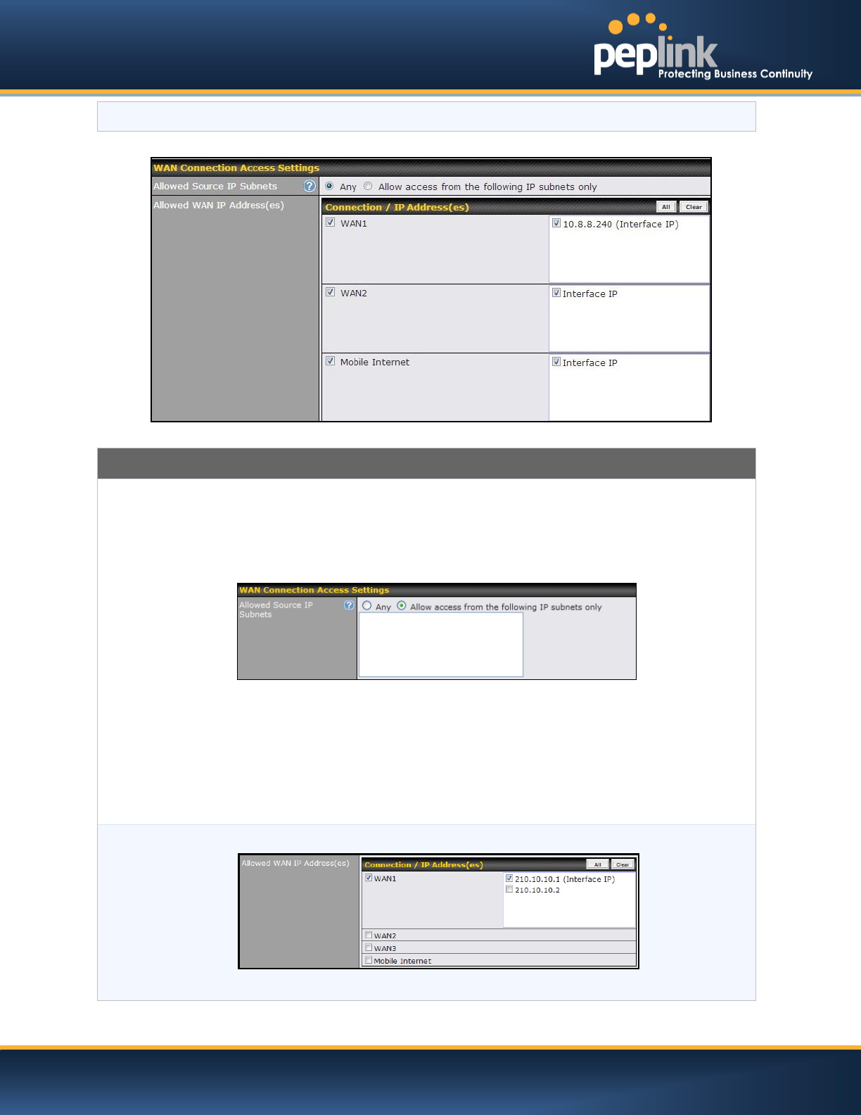
If LAN/WAN is chosen, the WAN Connection Access Settings form will be displayed.
WAN Connection Access Settings
Allowed Source IP
Subnets
This field allows you to restrict the ability to access web admin toonly defined IP subnets.
Any - Allow web admin accesses from anywhere, without IP address restrictions.
Allow access from the following IP subnets only - Restrictsthe ability to access
web admin to only defined IP subnets. When this is chosen, a text input area will
appear beneath:
Enter your allowed IP subnet addresses into this text area. Each IP subnet must be in the
form of w.x.y.z/m. w.x.y.z representsan IP address (e.g. 192.168.0.0), andm represents the
subnet mask in CIDR format, which is between 0 and 32 inclusively. For example:
192.168.0.0/24
To define multiple subnets, separate each IP subnet one in a line. For example:
192.168.0.0/24
10.8.0.0/16
Allowed WAN IP
Address(es)
This is to choose which WAN IP address(es) the web server should listen on.
USER MANUAL
Peplink Balance Series
http://www.peplink.com -181 / 227 - Copyright © 2014 Peplink
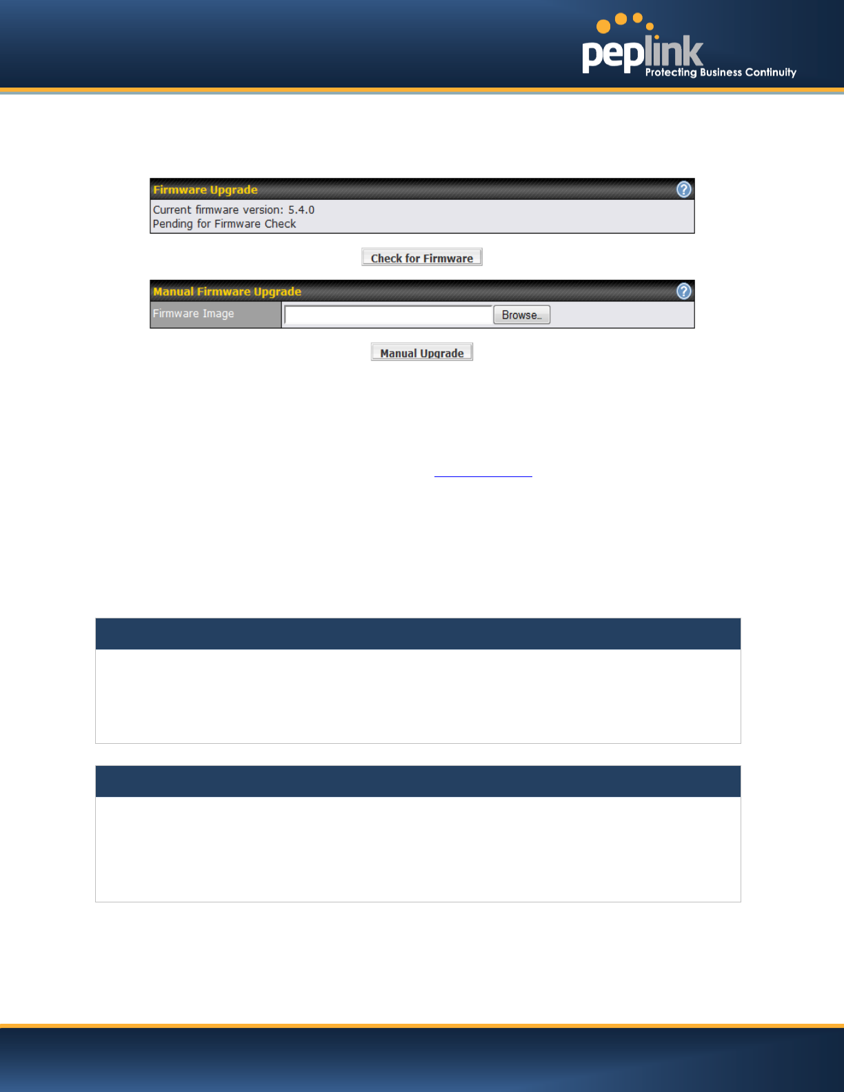
Firmware
The firmware of Peplink Balance is upgradeable through the Web Admin Interface.
Firmware upgrade functionality is located at:System>Firmware
There are two ways to upgrade the unit.The first method is through an online download,the system
canDownload and Upgradeover the Internet.The second method is to upload a firmware file manually.
To perform an online download, click on the Check for Firmware button.The Peplink Balance will check
online for new firmware. If new firmware is available, the Peplink Balance will automatically download the
firmware.The rest of the upgrade process will be automatically initiated.
You may also download a firmware image from the Peplink website and update the unit manually.To
update using a firmware image, click Browse…to select the firmware file from the local computer, and
thenclick Manual Upgradeto send the firmware to the Peplink Balance. It will then automatically initiate
the firmware upgrade process.
Please note that all Peplink devices are can store two different firmware versions in two different
partitions. A firmware upgrade will always replace the inactive partition. If you want to keep the inactive
firmware, you can simply reboot your device with the inactive firmware and then perform the firmware
upgrade.
Firmware Upgrade Status for Peplink Balance 20, 30, 30 LTE, 210 and 310
Status LED Information during firmware upgrade:
OFF – Firmware upgrade in progress (DO NOT disconnect power.)
Red –Unit is rebooting
Green –Firmware upgrade successfully completed
Important Note
The firmware upgrade process may not necessarily preserve the previous configuration, and the behavior varies on
a case-by-case basis. Consult the Release Notes for the particular firmware version before installing.
Do not disconnect the power during firmware upgrade process.
Do not attempt to upload a non-firmware file, or a firmware file that is not supported, by Peplink.
Upgrading Peplink Balance with an invalid firmware file will damage the unit, and may void the warranty.
USER MANUAL
Peplink Balance Series
http://www.peplink.com -182 / 227 - Copyright © 2014 Peplink
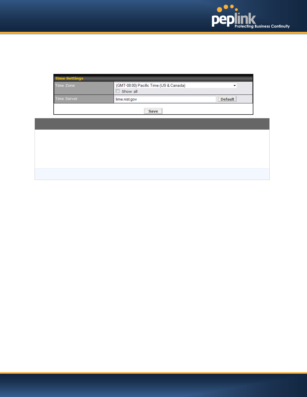
23.3 Time
The Time Server functionality enables the system clock of Peplink Balance to be synchronized with a
specified Time Server.
The settings for Time Server configuration are located at:System > Time
Time Server Settings
Time Zone
This specifies the time zone (along with the corresponding Daylight Savings Time scheme)
in which Peplink Balance operates.
The Time Zone value affects the time stamps in the Event Log of Peplink Balance and E-
mail notifications.
Checked the box Show all to show all time zone options.
Time Server
This setting specifies the NTP network time server to be utilized by Peplink Balance.
USER MANUAL
Peplink Balance Series
http://www.peplink.com -183 / 227 - Copyright © 2014 Peplink
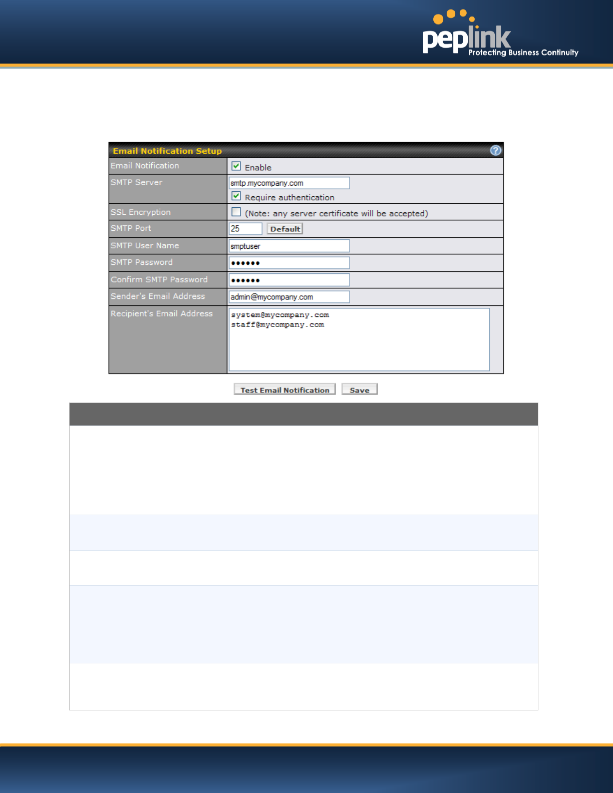
23.4 Email Notification
The Email Notification functionality of Peplink Balance provides a System Administrator with up to date
information on network status.
The settings for configuring Email Notification are found at: System> Email Notification
Email Notification Settings
Email Notification
This setting specifies whether or not to enable Email Notification.
If the box Enable is checked, then the Peplink Balance will sendemail messages to
theSystem Administrators when the WAN status changes, or when new firmware is
available.
If the box Enable is not checked, Email Notification is disabled and the Peplink Balance will
not send email messages.
SMTP Server
This setting specifies the SMTP server to be used for sending email. If the Server requires
authentication, check the box Require authentication.
SSL Encryption
Check the box to enable SMTPS. When the box is checked, the next field SMTP Port will
be changed to 465 automatically.
SMTP Port
This field is for specifying the SMTP Port number.
By default, this is set to 25; when the SSL Encryption box is checked, the default port
number will be set to 465.
You may customize the port number by editing this field. Click the button Default to restore
the number to its default setting.
SMTP User Name /
Password
This setting specifies the SMTP username and password while sending email. These
options are shown only if the Require authentication check box is checked in the SMTP
Server setting.
USER MANUAL
Peplink Balance Series
http://www.peplink.com -184 / 227 - Copyright © 2014 Peplink
Confirm SMTP
Password
This field allows you to verify and confirm the new administrator password.
Sender’s Email
Address
This setting specifies the email address which the Peplink Balance will use to send its
reports.
Recipient’s Email
Address
This setting specifies the email address(es) to which the Peplink Balance will send email
notifications. For multiple recipients, separate each email using the enter key.
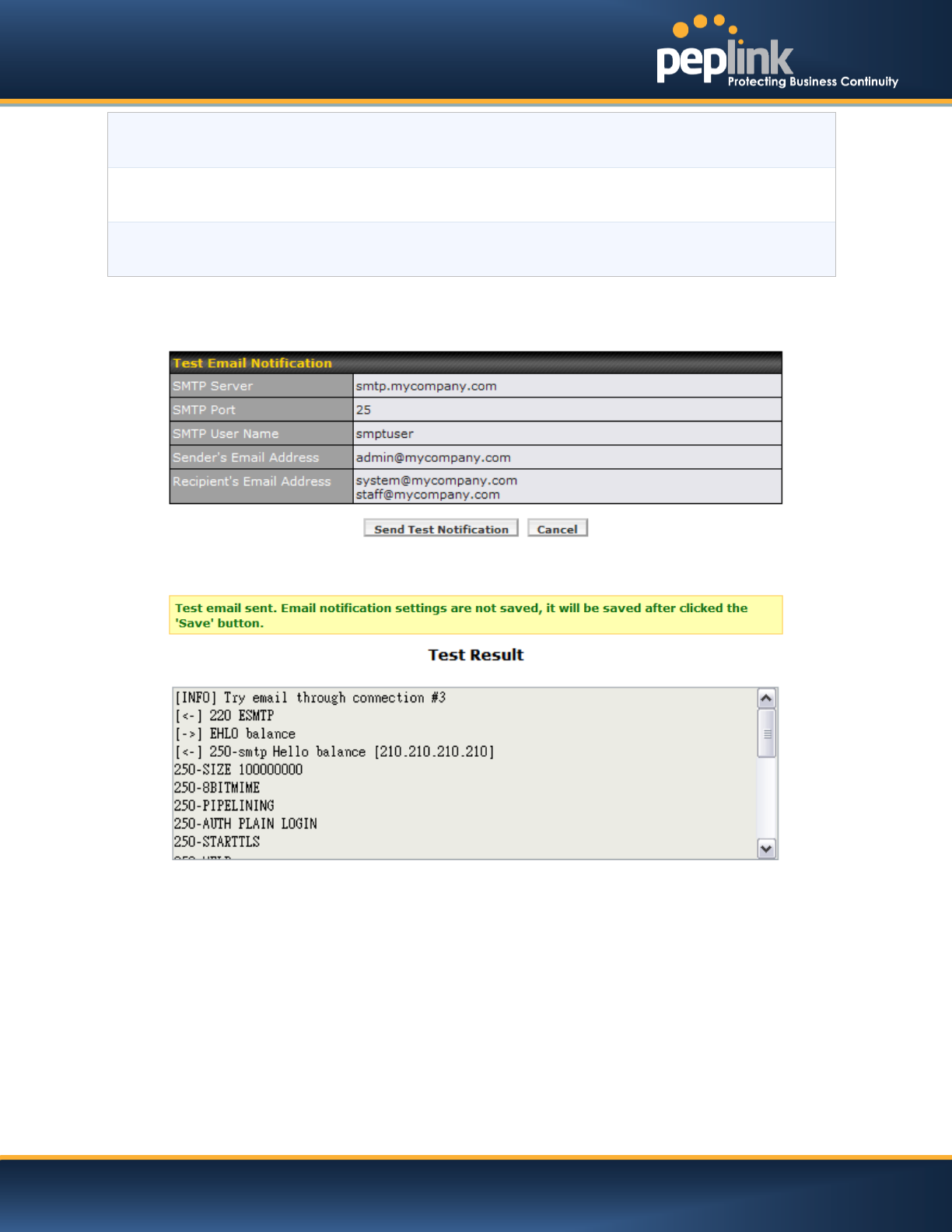
After you have completed the settings, you can click the Test Email Notificationbutton to test the
settings before saving it. After it is clicked, you will see this screen to confirm the settings:
ClickYes to confirm. In a few seconds, you will see a message with detailed test results.
USER MANUAL
Peplink Balance Series
http://www.peplink.com -185 / 227 - Copyright © 2014 Peplink
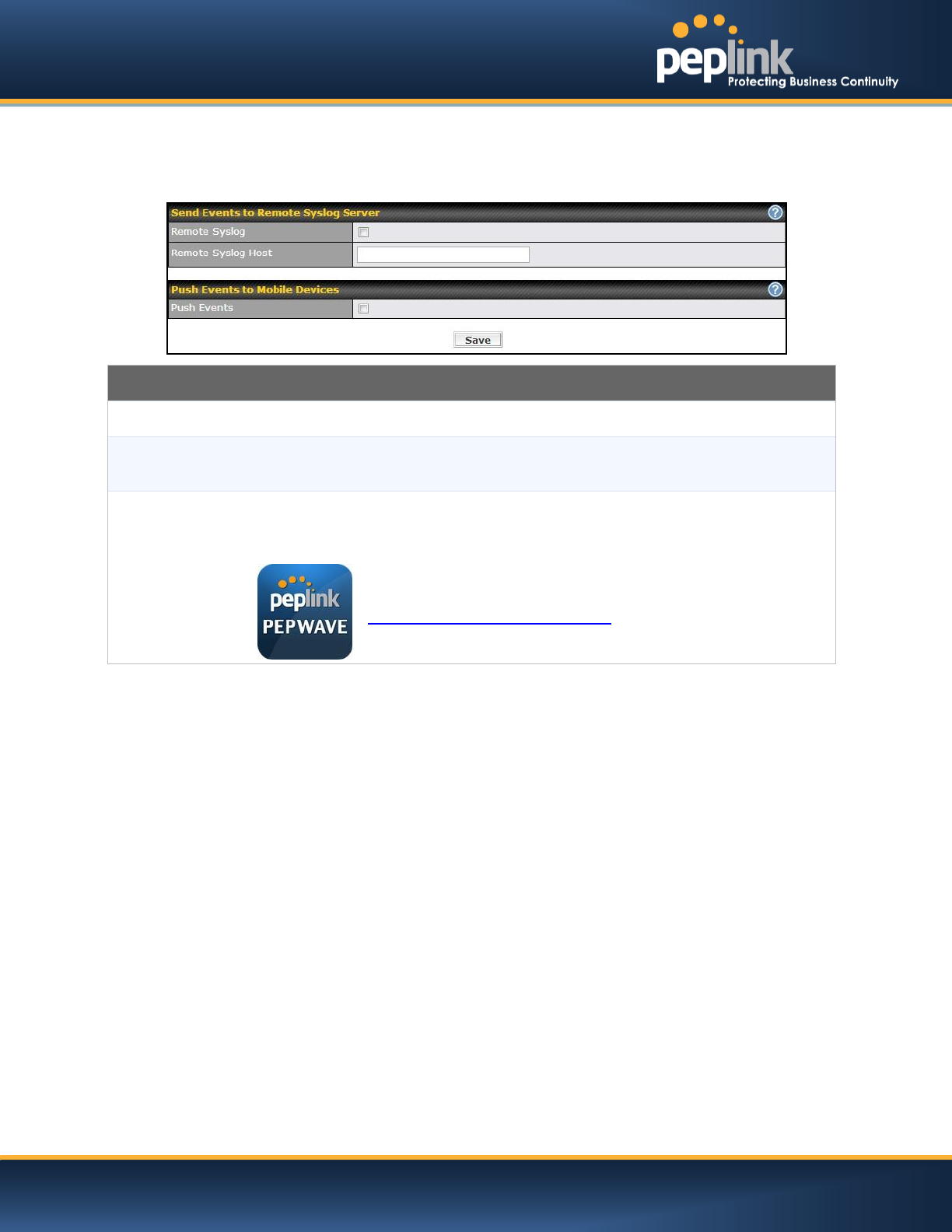
23.5 Event Log
The Event Log functionality enables event logging at a specified remote Syslog server.The settings for
configuring Remote System Log are found at: System>Event Log
Remote Syslog Settings
Remote Syslog
This setting specifies whether or not to log events at the specified remote Syslog server.
Remote Syslog
Host
This setting specifies the IP address or hostname of the remote Syslog server.
Push Events
The Peplink Balance can also send push notifications to mobile devices that have our
Mobile Router Utility installed. Click the square to activate this feature.
For more information regarding the Router Utility, please go to:
www.peplink.com/products/router-utility
USER MANUAL
Peplink Balance Series
http://www.peplink.com -186 / 227 - Copyright © 2014 Peplink
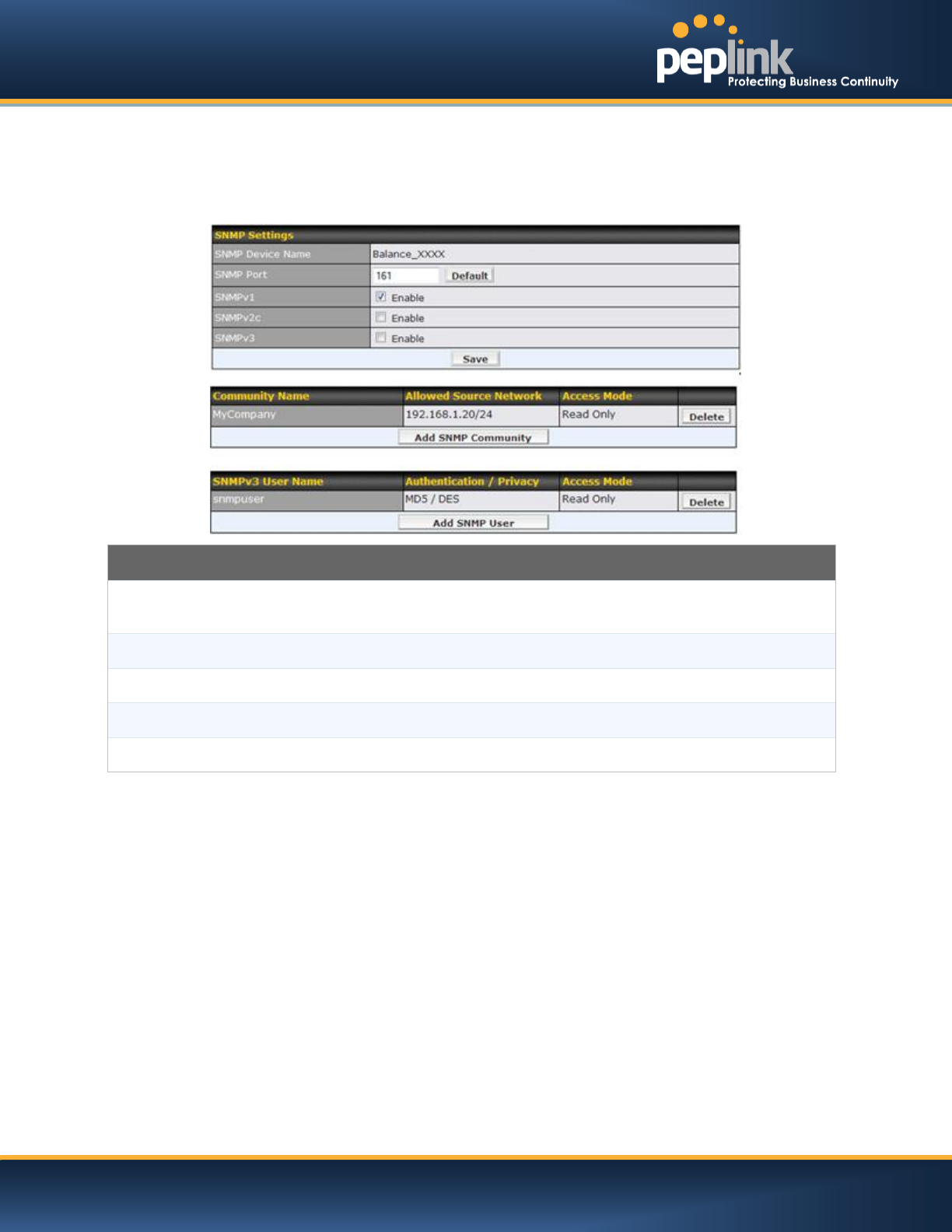
23.6 SNMP
SNMPor Simple Network Management Protocolis an open standard that can be used to collect
information about the Peplink Balance unit.
SNMP configuration is located at:System> SNMP
SNMP Settings
SNMP Device
Name
This field shows the router name defined in System > Admin Security.
SNMP Port
This option specifies the port which SNMP used. The default port is set as 161.
SNMPv1
This option allows you to enable SNMP version 1.
SNMPv2
This option allows you to enable SNMP version 2.
SNMPv3
This option allows you to enable SNMP version 3.
USER MANUAL
Peplink Balance Series
http://www.peplink.com -187 / 227 - Copyright © 2014 Peplink
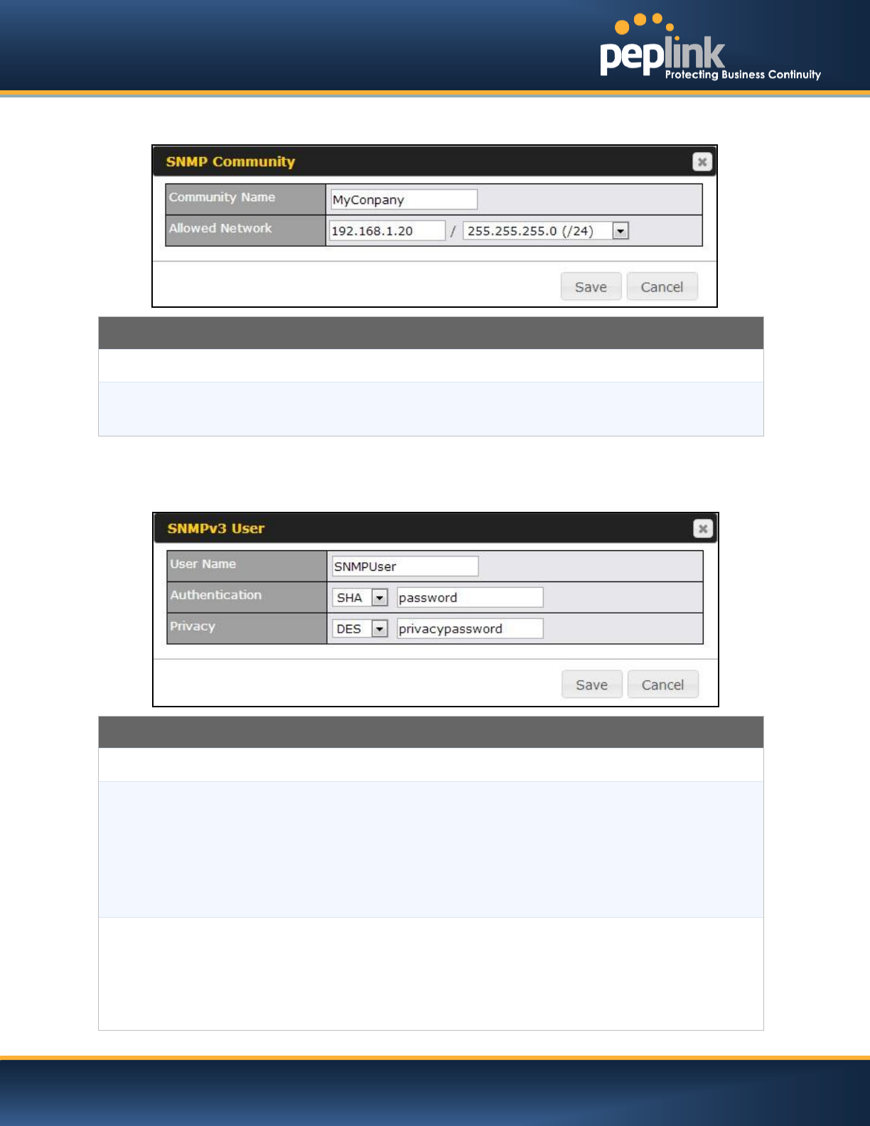
To add a community for either SNMPv1 or SNMPv2, click theAdd SNMP Communitybutton in the
Community Nametable, upon which the following screen is displayed:
SNMP Community Settings
Community Name
This setting specifies the SNMP Community Name.
Allowed Source
Subnet Address
This setting specifies a subnet from which access to the SNMP server is allowed.
Enter subnet address here (e.g. 192.168.1.0) and select the appropriate subnet mask.
To define a user name for SNMPv3, click Add SNMP Userin the SNMPv3 User Nametable, upon which
the following screen is displayed:
SNMPv3 User Settings
User Name
This setting specifies a user name to be used in SNMPv3.
Authentication
Protocol
This setting specifies via a drop-down menu the one of the following valid
authentication protocols:
NONE
MD5
SHA
When MD5 or SHA is selected, an entry field will appear for the password.
Privacy Protocol
This setting specifies via a drop-down menu the one of the following valid privacy
protocols:
NONE
DES
When MD5 or SHA is selected, an entry field will appear for the password.

USER MANUAL
Peplink Balance Series
http://www.peplink.com -188 / 227 - Copyright © 2014 Peplink
23.7 InControl
InControl is a cloud based service which allows you to manage all of your Peplink and Pepwave devices
with one unified system. With it, you can generate reports, gather statistics, and configure your devices
automatically. All of this is now possible with InControl.
When this check box is checked, the device's status information will be sent to the Peplink InControl
system. This device's usage data and configuration will be sent to the system if you enable the features in
the system.
You can sign up for an InControl account at https://incontrol2.peplink.com/. You can register your devices
under the account, monitor their status, see their usage reports and receive offline notifications.
USER MANUAL
Peplink Balance Series
http://www.peplink.com -189 / 227 - Copyright © 2014 Peplink
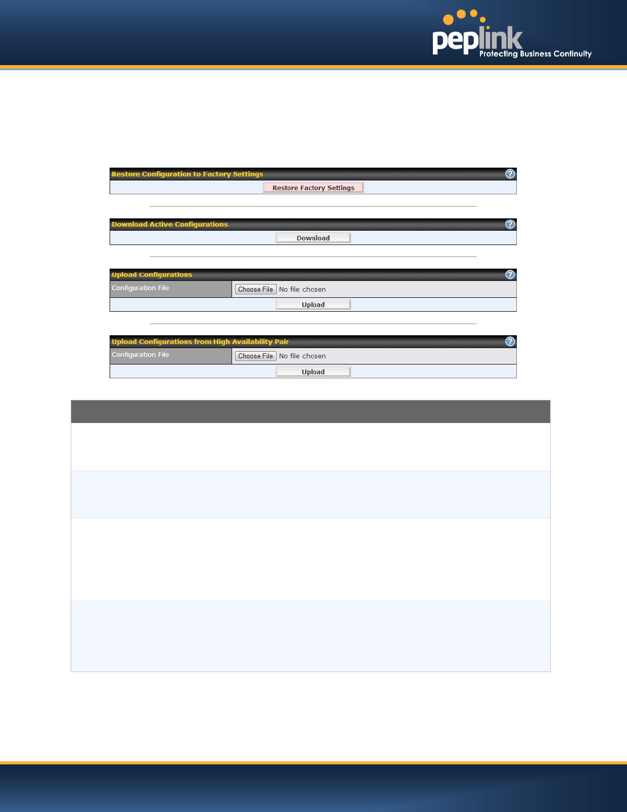
23.8 Configuration
Backing up the Peplink Balance settings immediately after the successful completion of the initial setup is
strongly recommended.
The functionality to download and upload Peplink Balance settings is found at:
System> Configuration
Configuration
Restore
Configuration to
Factory Settings
The Restore Factory Settings button is to reset the configuration to the factory default
settings. After clicking the button, you will need to click the Apply Changes button on the
top right corner to make the settings effective.
Downloading
Active
Configurations
The purpose of the Download button is to backup the current active settings. Click
Download and save the configuration file.
Uploading
Configurations
To restore or change settings based on a configuration file, click Choose File to locate the
configuration file on the local computer, and then click Upload.
The new settings can then be applied by clicking the Apply Changes button on the page
header, or you can cancel the procedure by pressing discard on the Main page of Web
Admin Interface.
Uploading
Configuration from
High Availability
Pair
(Available on Peplink Balance 210+)
In a High Availability (HA) configuration, the Balance unit can quickly load the configuration
of its HA counterpart. To do so, click the Upload button.
After loading the settings, configure the LAN IP address of the Peplink Balance unit to be
different from the HA counterpart.
USER MANUAL
Peplink Balance Series
http://www.peplink.com -190 / 227 - Copyright © 2014 Peplink
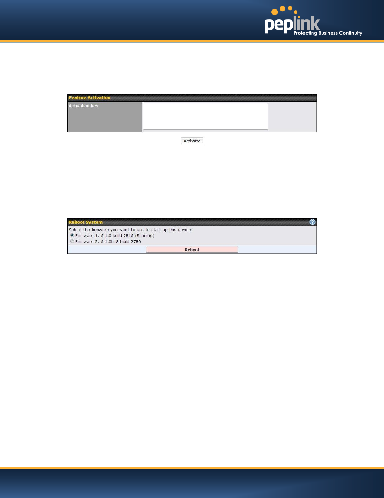
23.9 Feature Add-ons
Some balance models have features that could be activated upon purchase. Once the purchase is
complete, you will receive an Activation Key. Enter the key on the Activation Key field, click Activate,
and then click Apply Changes.
23.10 Reboot
This page provides a Reboot button for restarting the system.
For maximum reliability, the Peplink Balance series can equip with two copies of firmware; each copy a
different version. You can select the firmware version you would like to reboot the device with.
The firmware marked with (Running) is the current system boot up firmware.
Please note that a firmware upgrade will always replace the inactive firmware partition.
USER MANUAL
Peplink Balance Series
http://www.peplink.com -191 / 227 - Copyright © 2014 Peplink
24 Tools
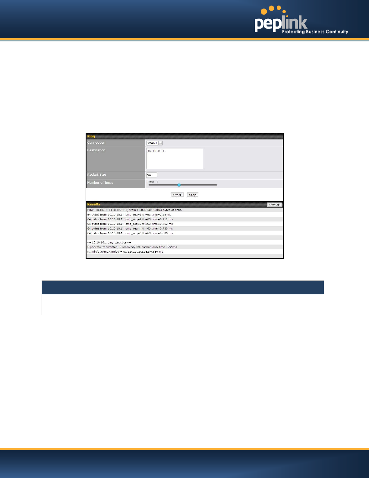
24.1 Ping
The Ping Test tool in the Peplink Balance performs Pings through a specified Ethernet interface or a
SpeedFusionTM VPN connection. You can specify the number of pings in the fieldNumber of timesto a
maximum number of 10 times, and Packet Size can be specified in the fieldPacket Size to a maximum of
1472 bytes.
The Ping utility is located at System> Tools > Ping, illustrated as follows:
Tip
A System Administrator can use the Ping utility to manually check the connectivity of a particular LAN/WAN
connection.
USER MANUAL
Peplink Balance Series
http://www.peplink.com -192 / 227 - Copyright © 2014 Peplink
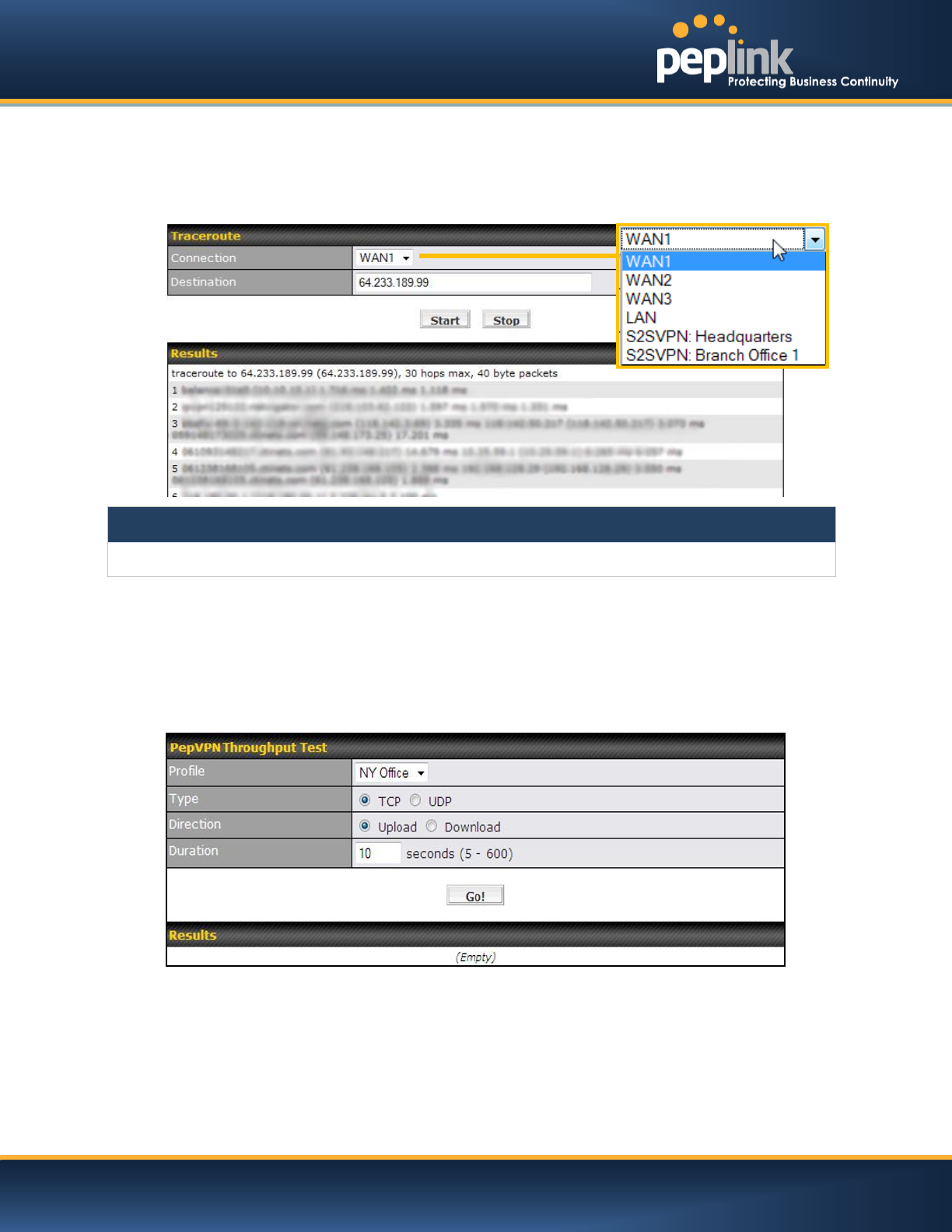
24.2 Traceroute Test
The Traceroute Test tool traces the routing path to the destination through a particular Ethernet interface
or a SpeedFusionTMconnection. The Traceroute Test utility is located at System> Tools >Traceroute.
Tip
A System Administrator can use the Traceroute utility to analyze the connection path of a LAN/WAN connection.
24.3 PepVPN Test
(Available on Peplink Balance 210+)
The PepVPN Test tool can help to test the throughput between different VPN peers.
You can define the Test Type,Direction, and Duration of the test, and press Go!to perform the
throughput test.The VPN Test utility is located at System > Tools >PepVPN Testillustrated as follows:
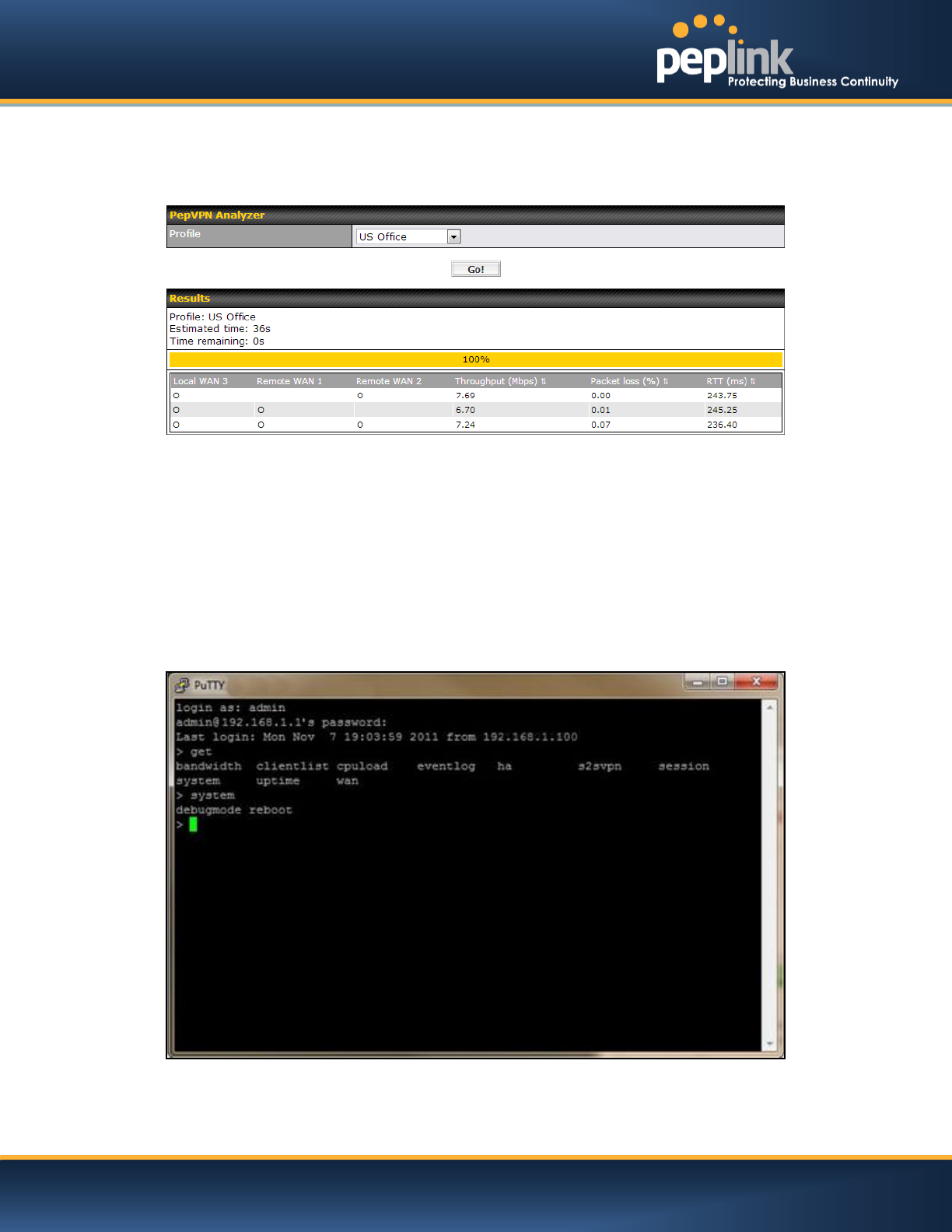
24.4 PepVPN Analyzer
The bandwidthbonding feature of PepVPN occurs when multiple WAN lines from one end merge with
multiple WAN lines from the other end. For this to happen, each WAN line needs to form a connection
with all the WAN lines on the opposite end. The function of the PepVPN Analyzer is to report the
throughput, packet loss, and latency of all possible combinations of connections.
USER MANUAL
Peplink Balance Series
http://www.peplink.com -193 / 227 - Copyright © 2014 Peplink
This feature is located in System > PepVPN Analyzer.To utilize this feature, simply choose your profile
from the drop-down menu and clickGo!
24.5 CLI (Command Line Interface Support)
The serial console connector with the Peplink Balance 305, 380 HW rev 5, Peplink Balance 580, Peplink
Balance 710 HW rev 2, Peplink Balance 1350 and Peplink Balance 2500 is RJ-45.To access the serial
console port, prepare a RJ-45 to DB-9 console cable. Connect the RJ-45 end to the unit's console port
and the DB-9 end to a terminal's serial port. The port setting will be 115200,8N1.
The serial console connector with the Peplink Balance 305, 380 HW rev 1 to 4, Peplink Balance 710 HW
rev 1 is DB-9 male connector. To access the serial console port, connect a null modem cable with a DB-9
connector on both ends to a terminal with the port setting of 115200,8N1.
USER MANUAL
Peplink Balance Series
http://www.peplink.com -194 / 227 - Copyright © 2014 Peplink
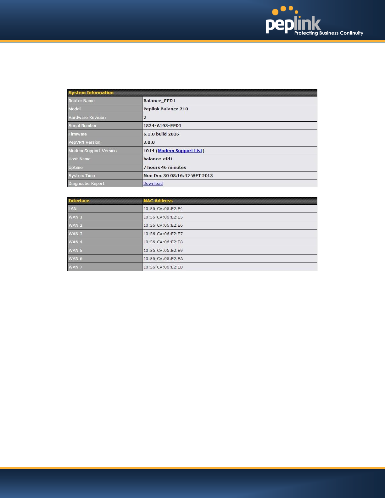
25 Status
25.1 Device
System information is located at Status>Device:

USER MANUAL
Peplink Balance Series
http://www.peplink.com -195 / 227 - Copyright © 2014 Peplink
System Information
Router Name
This is the name specified in the field Router Name located in System > Admin Security.
Model
This shows the model name and number of this device.
Hardware Revision
This shows the hardware version of this device.
Serial Number
This shows the serial number of this device.
Firmware
This shows the firmware version this device is currently running.
Uptime
This shows the length of time since the device has been rebooted.
System Time
This shows the current system time.
Diagnostic Report
The Download button is for exporting a diagnostic report file required for system
investigation.
The second table shows the MAC address of each LAN/WAN interface connected.
Important Note
If you encounter issues and would like to contact Peplink Support Team (http://www.peplink.com/contact/), please
download the diagnostic report file and attach it along with a description of your encountered issue.
In firmware 5.1 or before, Diagnostic Report file can be obtain at System > Reboot
USER MANUAL
Peplink Balance Series
http://www.peplink.com -196 / 227 - Copyright © 2014 Peplink
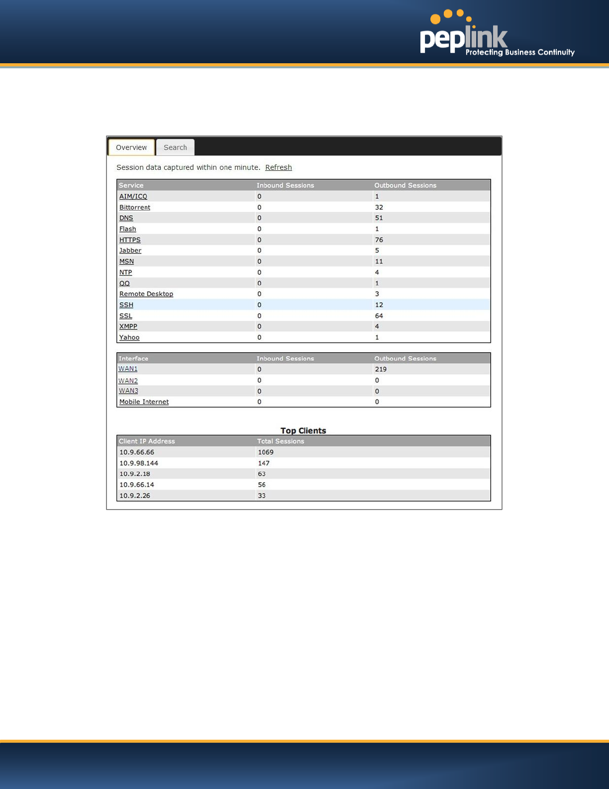
25.2 Active Sessions
Information on Active Sessions is at: Status > Active Sessions> Overview
This screen displays the number of sessions initiated by each application. Click on each Service to obtain
additional information. This screen also indicates the number of sessions initiated by each WAN port.
Finally, you can see which clients are initiating the most sessions.
USER MANUAL
Peplink Balance Series
http://www.peplink.com -197 / 227 - Copyright © 2014 Peplink
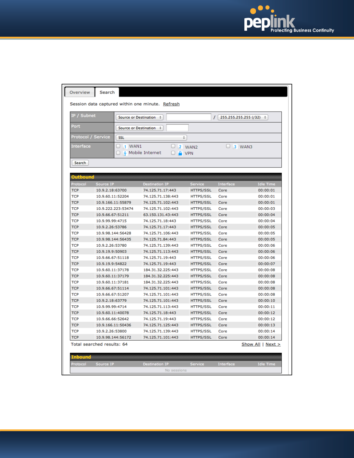
In addition, you can also perform a filtered search for specific sessions. You can filter by subnet, port,
protocol, and interface. To perform a search, navigate to: Status > Active Sessions> Search
This Active Sessions section displays the active inbound / outbound sessions of each WAN connection
on Peplink Balance.
A filter is available to help sort out the active session information.Enter a keyword in the field or check one
of the WAN connection boxes for filtering.
USER MANUAL
Peplink Balance Series
http://www.peplink.com -198 / 227 - Copyright © 2014 Peplink
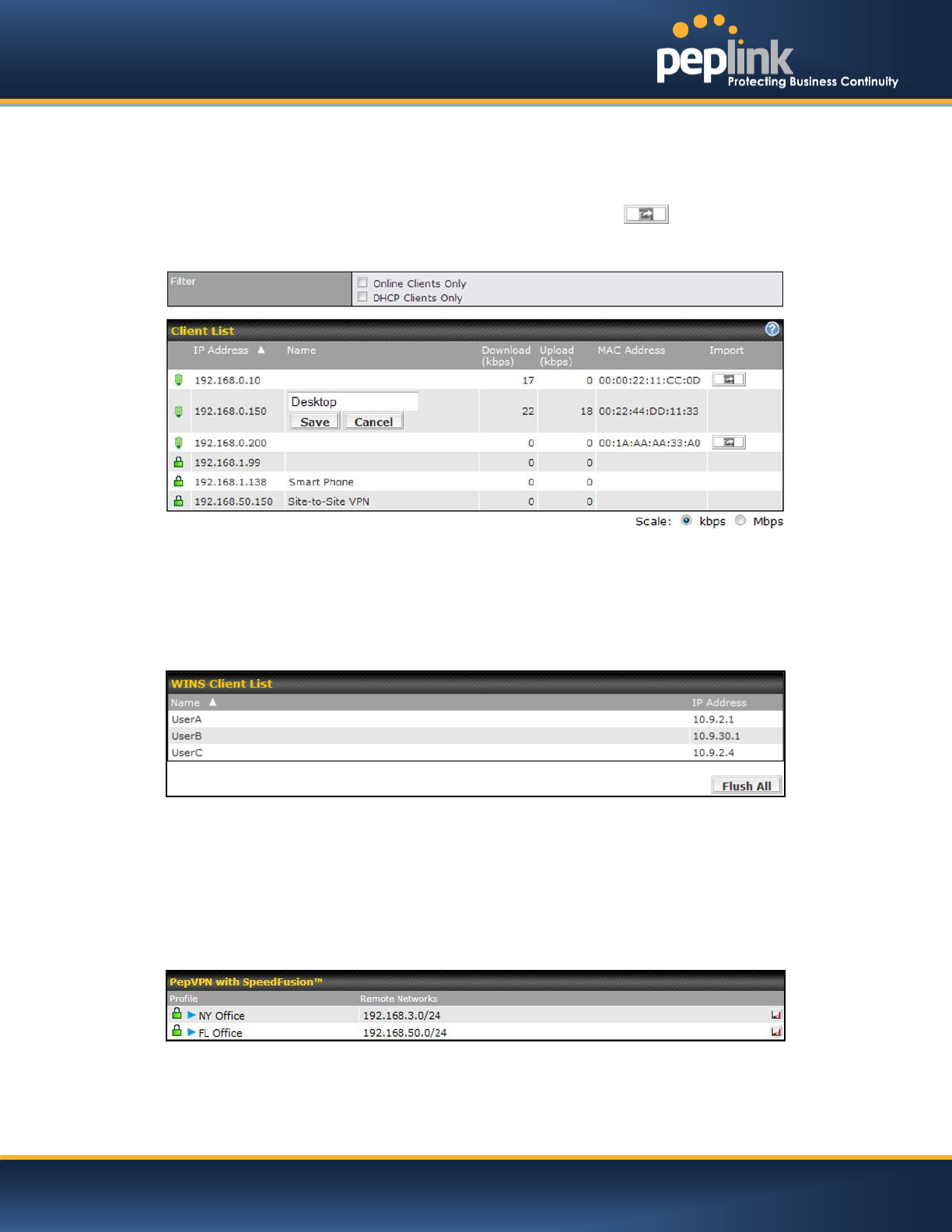
25.3 Client List
The client list table is located at Status > Client List.It lists DHCP and online client IP addresses: their
Name (retrieved from DHCP reservation table or defined by users), their current Download and Upload
rate and the MAC address.
Clients can be imported into the DHCP Reservation table by clicking the button on the right-most
column. Further update the record after the import by going to Network > LAN.
If PPTP Server in section 21.2,SpeedFusionTM in section12.1, or AP Controller in section 17is enabled,
you may see the corresponding connection name listed in the Namefield.
25.4 WINS Client
The WINS client list table is located at Status >WINS Client.
It lists the IP addresses and Names of WINS clients. This option will only be available when you have
enabled the WINS Server in section 0.Name of clients retrieved will be automatically matched into Client
List in the previous section.Click the button Flush All to flush all WINS client records.
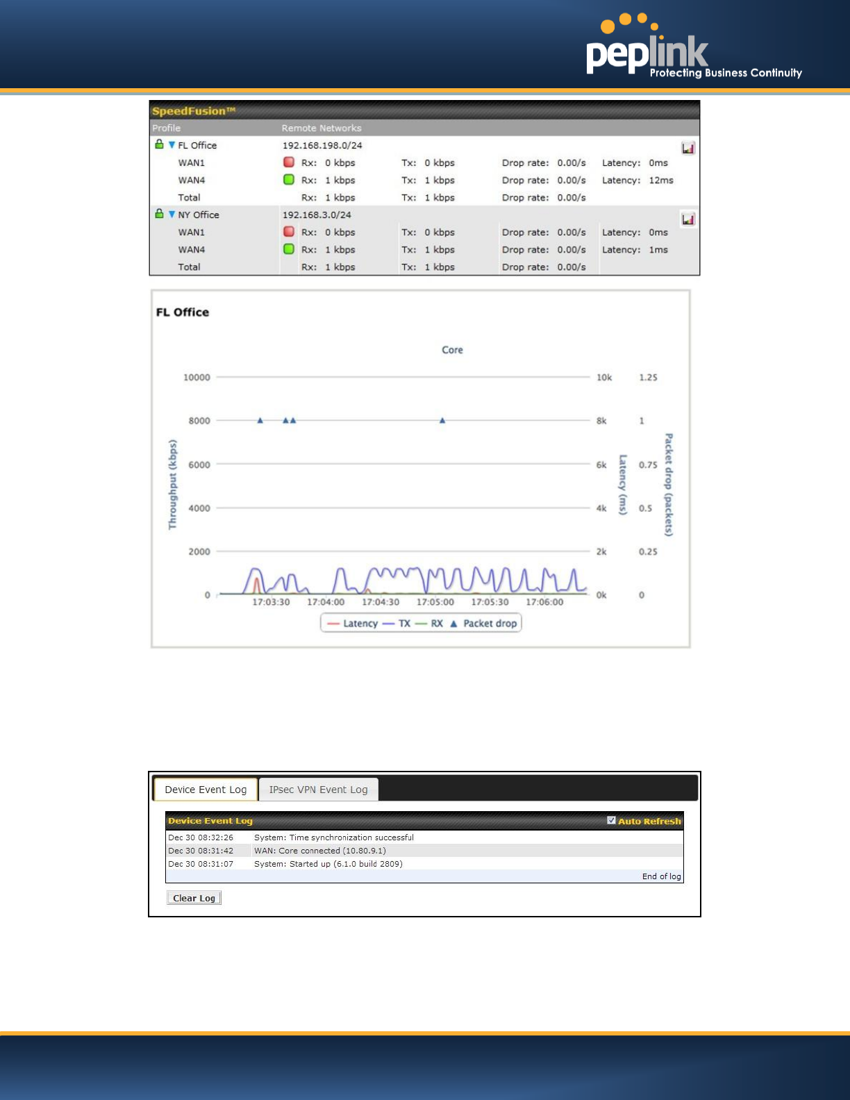
25.5 SpeedFusionTMStatus
This is a page showing the current status of SpeedFusionTM, located at: Status >SpeedFusionTM
Details about SpeedFusionTMconnection peers would be shown as below.
You can simply click on the corresponding peer name to explore the WAN connection(s) status and
subnet information of each VPN peer.
USER MANUAL
Peplink Balance Series
http://www.peplink.com -199 / 227 - Copyright © 2014 Peplink
25.6 Event Log
Event Loginformation is located at: Status>Event Log
25.6.1 Device Event Log
The log section displays a list of events that has taken place on the Peplink Balance unit.Click the
Refresh button to retrieve log entries again. Click the Clear Log button to clear the log. Select 50, 100,
or allto show the corresponding number of events in the log.
USER MANUAL
Peplink Balance Series
http://www.peplink.com -200 / 227 - Copyright © 2014 Peplink
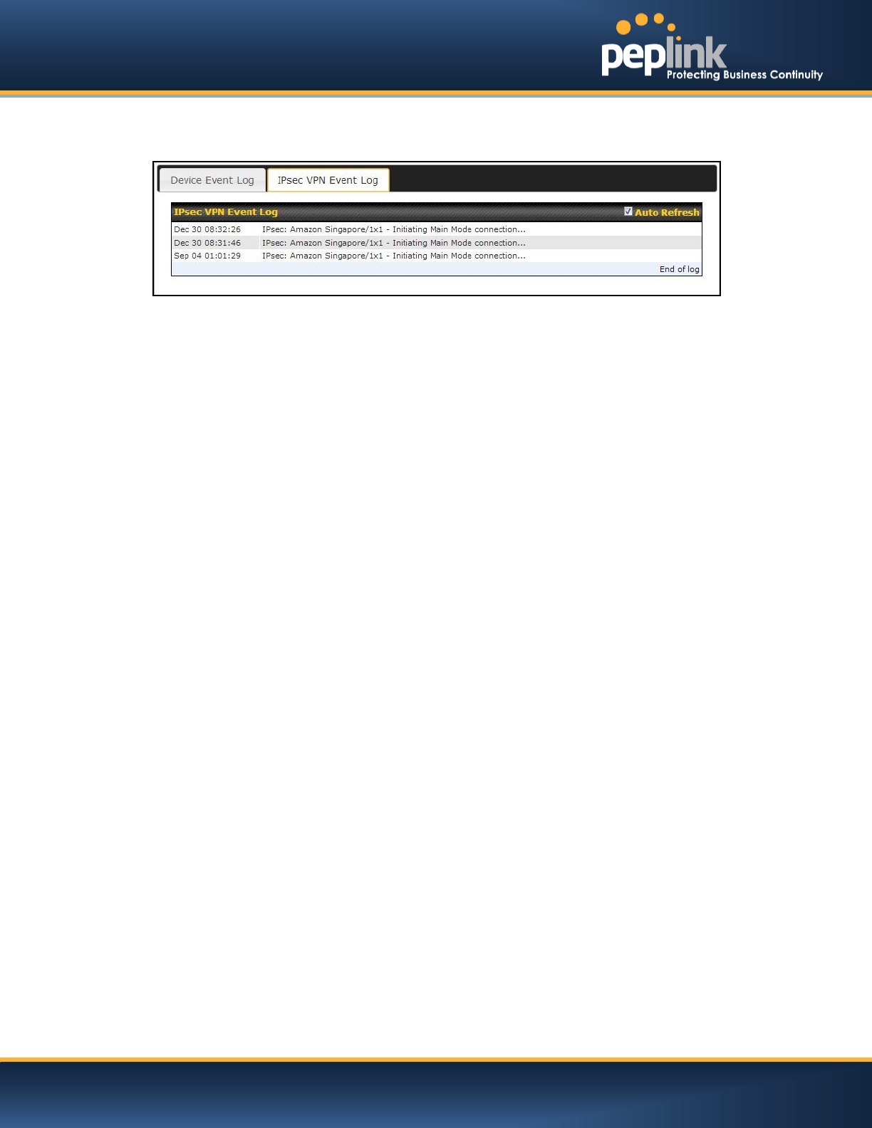
25.6.2 IPsec Event Log
This section displays a list of events that has taken place within an IPsec VPN connection. Check the box
next to Auto Refresh and the log will be refreshed automatically.
For an AP event Log, navigate to: AP > Info
25.7 Bandwidth
This section shows the bandwidth usage statistics, located at: Status >Bandwidth.
Bandwidth usage at the LAN while the device is switched off (e.g. LAN Bypass) are neither recorded nor
shown.
USER MANUAL
Peplink Balance Series
http://www.peplink.com -201 / 227 - Copyright © 2014 Peplink
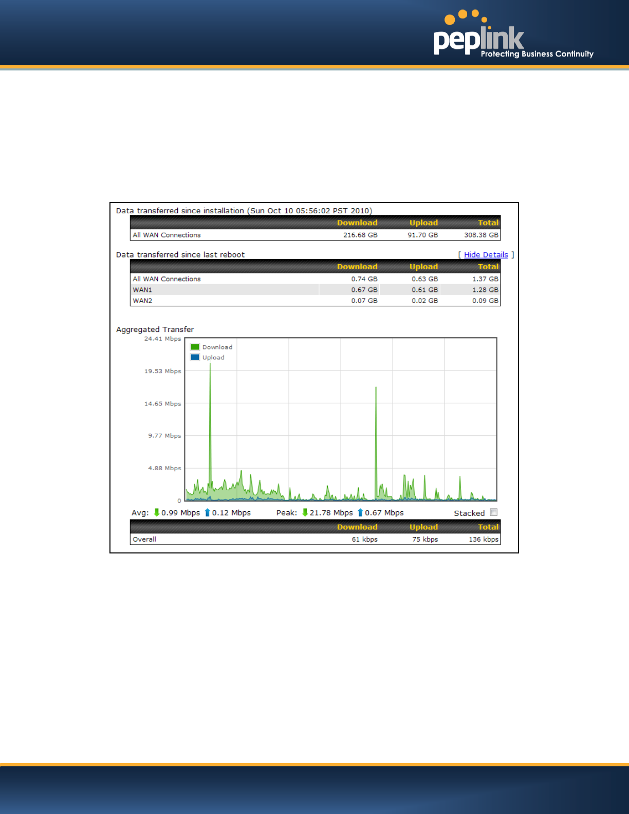
25.7.1 Real-Time
The Data transferred since installationtable indicates how much network traffic has been processed by
the device since first bootup.The Data transferred since last reboot table indicates how much network
traffic has been processed by the device since the last bootup.
Click the Show Detailslink on the top right hand corner of each table, anda breakdown of the data
transferred will be shown.The check box Stacked below the data transferred graph can be checked to
show the aggregated transferred rate of both traffic directions.
USER MANUAL
Peplink Balance Series
http://www.peplink.com -202 / 227 - Copyright © 2014 Peplink
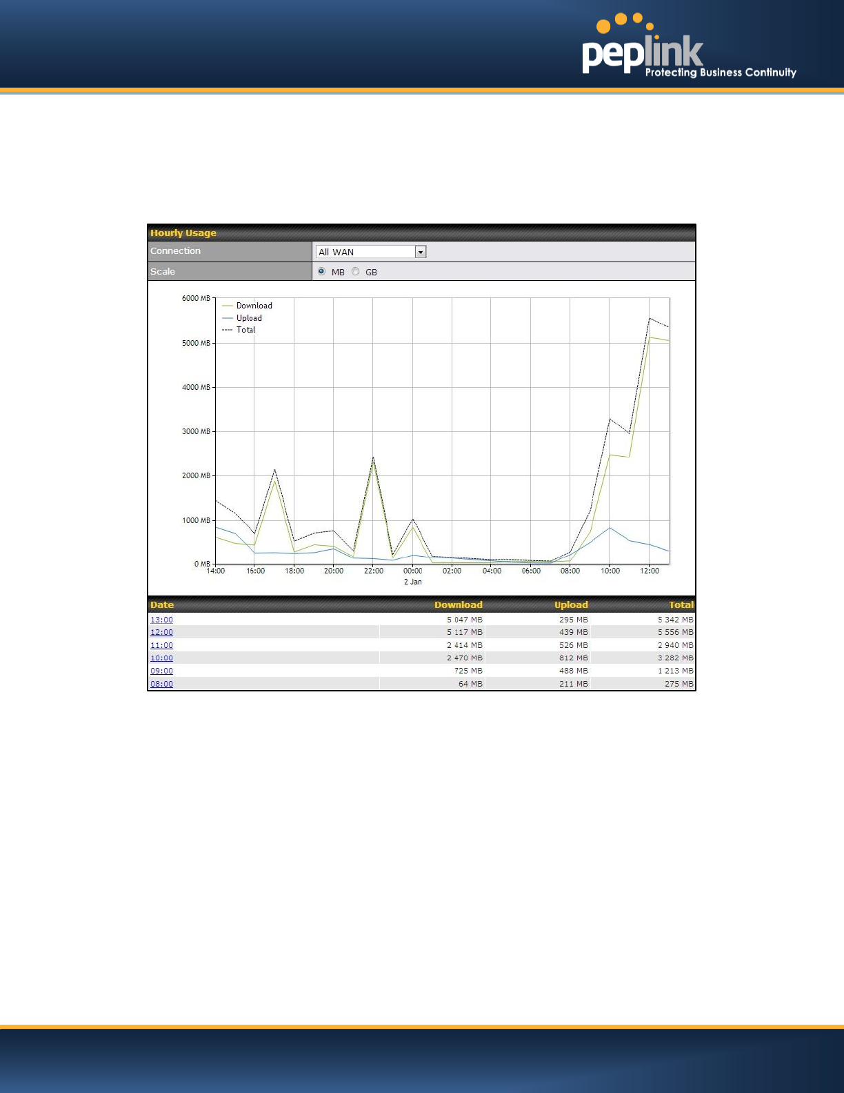
25.7.2 Hourly
This page shows the hourly bandwidth usage for all WAN connections, with the option of viewing each
individual connection.
Select the desired connection to check from the drop down menu.
USER MANUAL
Peplink Balance Series
http://www.peplink.com -203 / 227 - Copyright © 2014 Peplink
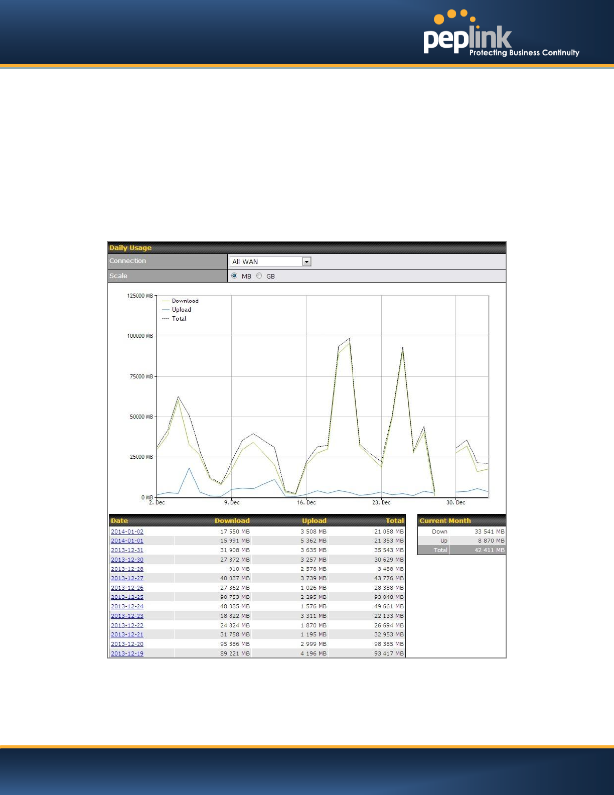
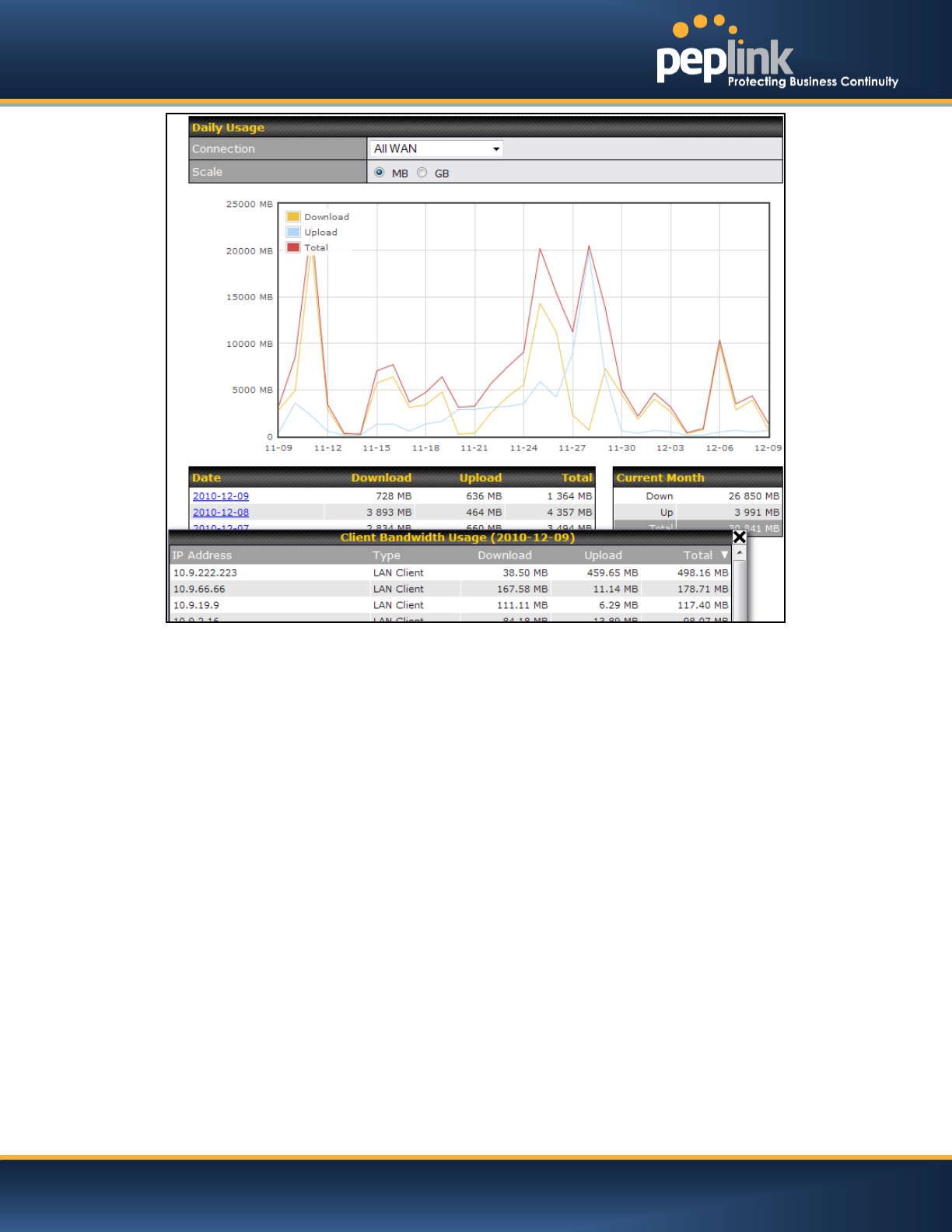
25.7.3 Daily
This page shows the daily bandwidth usage for all WAN connections, with the option of viewing each
individual connection.
Select the connection to check from the drop down menu.If you have enabled theBandwidth
Monitoringfeature as shown in section 11.4, the Current Billing Cycletable for that WAN connection will
be displayed.
Click ona date to view the client bandwidth usage of that specific date. This feature is not available if you
have selected to view the bandwidth usage of only a particular WAN connection.
The Scale of the graph can be set to show in Megabyte (MB) or Gigabyte (GB).
Status
USER MANUAL
Peplink Balance Series
http://www.peplink.com -204 / 227 - Copyright © 2014 Peplink
Click on a specific date to receivea breakdown of all client usage for that date.
USER MANUAL
Peplink Balance Series
http://www.peplink.com -205 / 227 - Copyright © 2014 Peplink
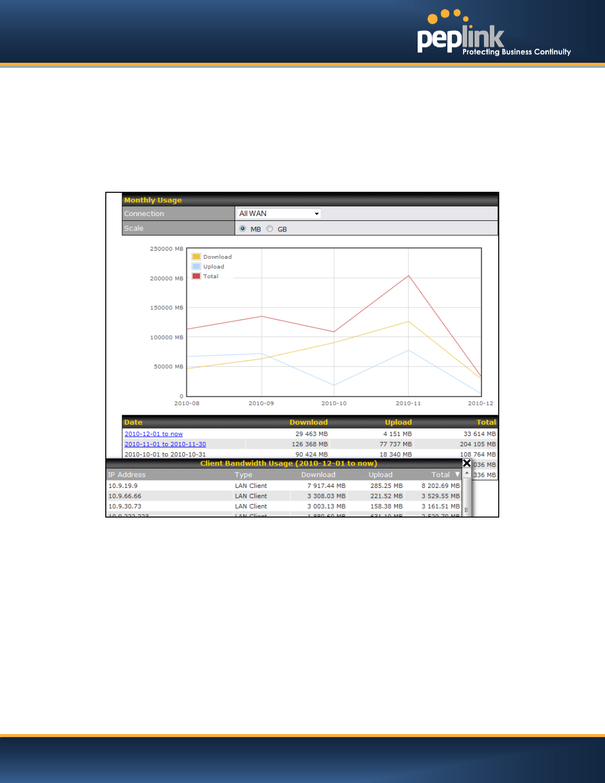
25.7.4 Monthly
This page shows the monthly bandwidth usage for each WAN connection.
If you have enabled Bandwidth Monitoringfeature as shown in section11.4, you can check the usage of
each particular connection and view the information byBilling Cycle or byCalendar Month.
Click the first two rows to view the client bandwidth usage on the last two months.This feature is not
available if you have chosen to view the bandwidth of an individual WAN connection.
The Scale of the graph can be set to show in Megabyte (MB) or Gigabyte(GB).
Click on a specific month to receive a breakdown of all client usage for that month.

USER MANUAL
Peplink Balance Series
http://www.peplink.com -206 / 227 - Copyright © 2014 Peplink
Appendix A. Restoration of Factory Defaults
To restore the factory default settings on a Peplink Balance unit, perform the following:
For Balance 20/30/30 LTE/210/310:
1. Locate the reset button on the Peplink Balance unit.
2. With a paper clip, press and keep the reset button pressed for at least 10 seconds, until the unit
reboots itself.
For Balance 305/380/580/710/1350/2500:
Use the buttons on front panel to control the LCD menu to go to Maintenance>Factory Defaults,
and then choose Yes to confirm.
Afterwards, the factory default settings will be restored.
Important Note
All user settings will be lost after restoring the factory default settings.
Regular backup of configuration parameters is strongly recommended.
USER MANUAL
Peplink Balance Series
http://www.peplink.com -207 / 227 - Copyright © 2014 Peplink
Appendix B. Routing under DHCP, Static IP, and PPPoE
The information in this appendix applies only to situations where the Peplink Balance operates a WAN
connection under DHCP, Static IP, and PPPoE.
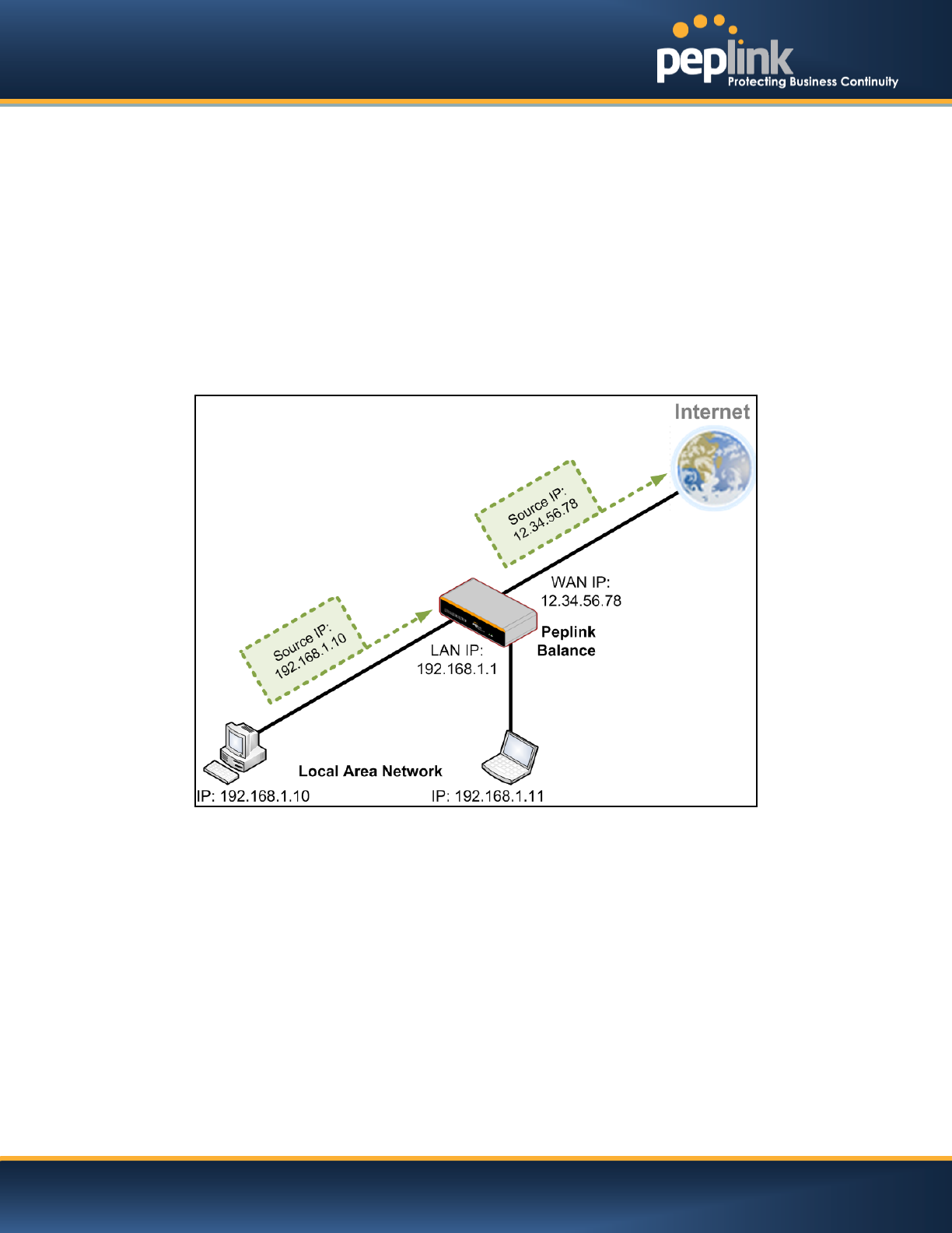
B.1 Routing via Network Address Translation (NAT)
When the Peplink Balance is operating under NAT mode, the source IP addresses of outgoing IP packets
are translated to the WAN IP address of Peplink Balance. With NAT, all LAN devices share the same
WAN IP address to access the Internet (i.e. the WAN IP address of Peplink Balance).
Operating the Peplink Balance in NAT mode requires only one WAN (Internet) IP address.In addition,
operating in NAT mode also has security advantages because LAN devices are hidden behind the
Peplink Balance.They are not directly accessible from the Internet, and, hence, less vulnerable to attacks.
The following figure shows the packet flow in NAT mode:
USER MANUAL
Peplink Balance Series
http://www.peplink.com -208 / 227 - Copyright © 2014 Peplink
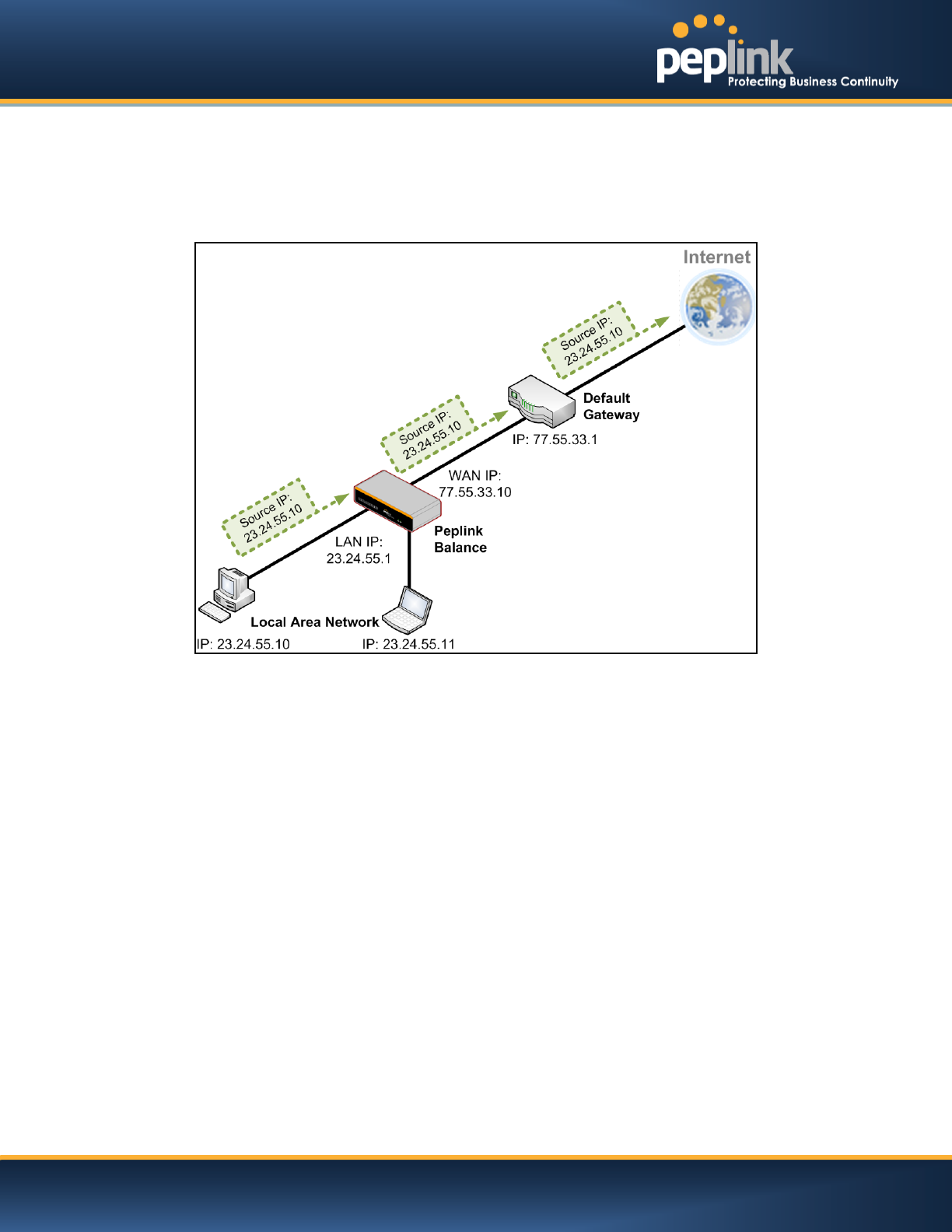
B.2 Routing via IP Forwarding
When Peplink Balance is operating under IP Forwarding mode, the IP addresses of IP packets are
unchanged; Peplink Balance forwards both inbound and outbound IP packets without changing their IP
addresses.
The following figure shows the packet flow in IP Forwarding mode:
USER MANUAL
Peplink Balance Series
http://www.peplink.com -209 / 227 - Copyright © 2014 Peplink
Appendix C. Case Studies
C.1 Performance Optimization
C.1.1 Scenario
In this scenario, email and web browsing are the two main Internet services used by the LAN users.
The mail server is external to the network. The connections are ADSL (WAN1, with slow uplink and fast
downlink) and Metro Ethernet (WAN2, symmetric).
C.1.2 Solution
For optimal performance with this configuration, individually set the WAN load balance according to the
characteristics of each service.
Web browsing mainly downloads data; sending e-mails mainly consumes upload bandwidth.
Both connectionsoffer good download speeds; WAN2 offers good upload speeds.
Define WAN1 and WAN2's inbound and outbound bandwidths to be 3M/512k and 4M/4M
respectively. This will ensure that outbound traffic is more likely to be routed through WAN2.
For HTTP, set the weight to 3:4.
For SMTP, set the weight to 1:8, such that users will have a greater chance to be routed via
WAN2 when sending e-mail.
C.1.3 Settings
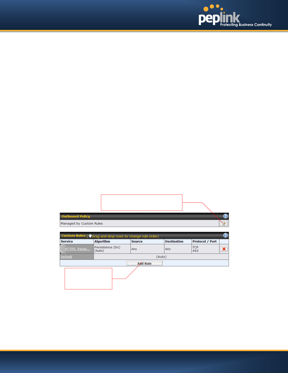
1. Add a new outbound traffic rule for HTTP.
2. Add a new outbound traffic rule for SMTP.
In general, to add a new outbound traffic rule, navigate toNetwork> Outbound Policy:
Click Add Rule to
add a new load
distribution rule.
Click here and Select Managed
by Custom Rules
USER MANUAL
Peplink Balance Series
http://www.peplink.com -210 / 227 - Copyright © 2014 Peplink
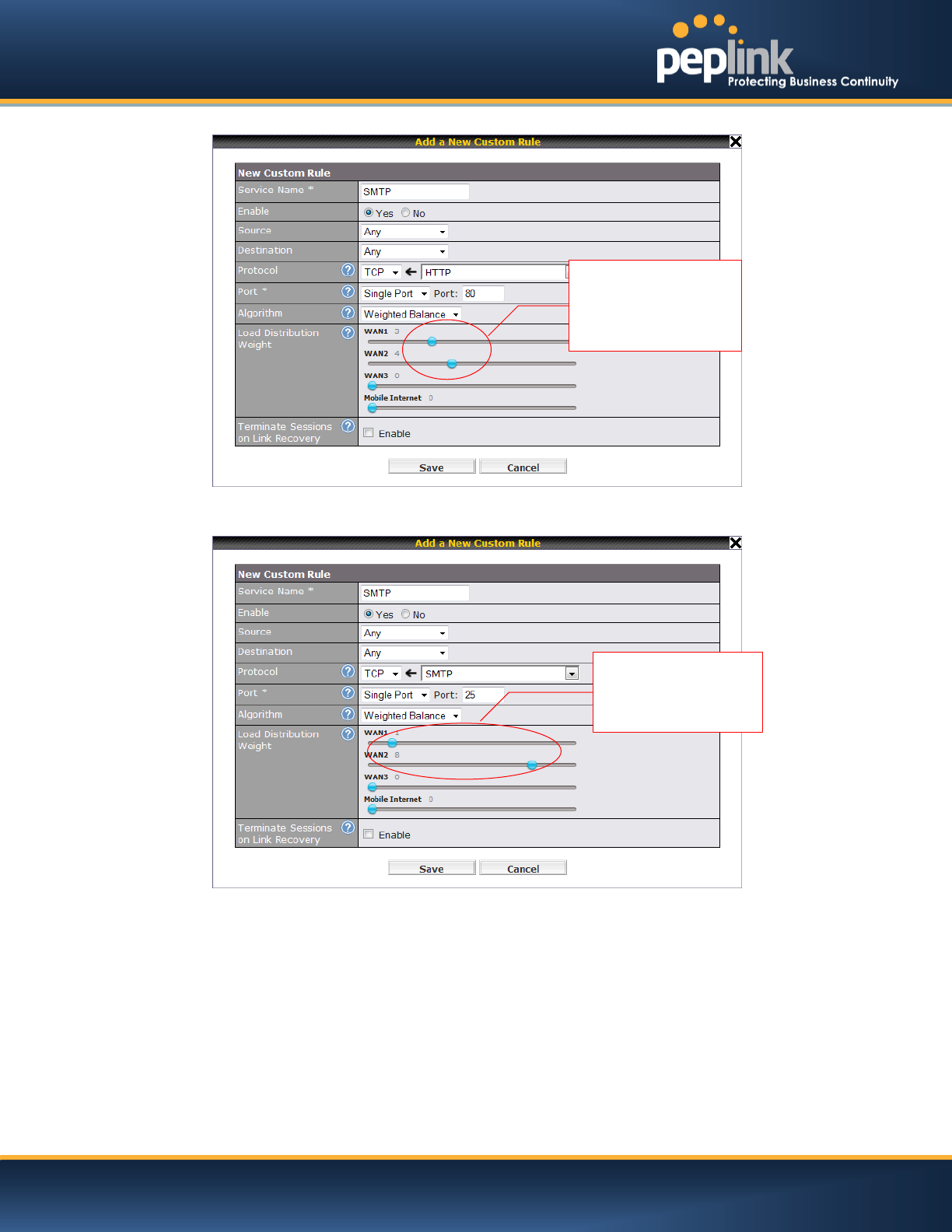
Settings for HTTP:
Settings for SMTP:
Set the weight of
WAN1 and WAN2 for
HTTP to 3 and 4,
respectively
Set the weight of
WAN1 and WAN2
for SMTP to 1 and
8, respectively
USER MANUAL
Peplink Balance Series
http://www.peplink.com -211 / 227 - Copyright © 2014 Peplink
C.2 Maintaining the Same IP Address throughout a Session
C.2.1 Scenario
Some IP address sensitive web sites (for example, Internet banking) use both client IP address and
cookie matching for session identification.Since load balancing uses different IP addresses, the session is
dropped when a mismatching IP is detected resulting in frequent interruptions while visiting such sites.
C.2.2 Solution
Make use of the Persistency functionality of Peplink Balance. With Persistence configuredand the
ByDestinationoption selected, the Peplink Balance will usea consistent WAN connection for source-
destination pairs of IP addresses,preventing sessions from being dropped.
With Persistence is configured and the option By Sourceis selected, Peplink Balance uses a consistent
WAN connection for same source IP addresses. This option offers higher application compatibility,but
may inhibit the load balancing function unless there are many clients using the internet.
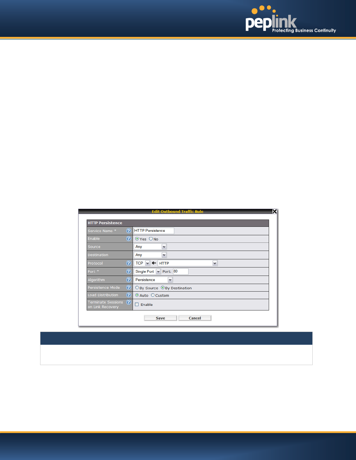
C.2.3 Settings
Set persistence in:
Network> Outbound Policy
Click Add Rule, select HTTP(TCP port 80) for web service, and select Persistence. Click Save and then
Click Apply Changes on the top right corner to complete the process.
Tip
A network administrator can use the Traceroute utility to manually analyze the connection path of a particular WAN
connection.
USER MANUAL
Peplink Balance Series
http://www.peplink.com -212 / 227 - Copyright © 2014 Peplink
C.3 Bypassing the Firewall to Access Hosts on LAN
C.3.1 Scenario
There are times when remote access to computers on the LAN is desirable; for example, when hosting
web sites, online businesses and FTP download and upload areas, etc.
In such cases, it may be appropriate to create an inbound NAT mapping for the network to allow some
hosts on the LAN to be accessible from outside of the firewall.
C.3.2 Solution
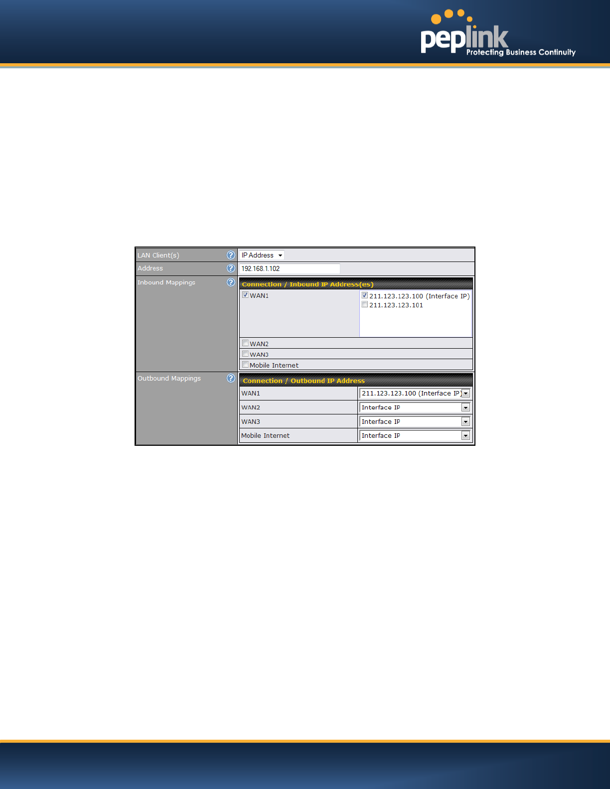
The Web Admin Interface can be used to add an inbound NAT mapping to a host and to bind the host to
the WAN connection(s) of your choice. To begin, navigate to Network>NAT Mappings> AddNAT Rule
In this example, the host with an IP address of 192.168.1.102 is bound to 211.123.123.100 of WAN1:
Click Apply Changes on the top right corner to complete the process.
USER MANUAL
Peplink Balance Series
http://www.peplink.com -213 / 227 - Copyright © 2014 Peplink
C.4 Inbound Access Restriction
C.4.1 Scenario
A firewall is required in order to protect the network from potential hacker attacks and other Internet
security threats.
C.4.2 Solution
Firewall functionality is builtinto the Peplink Balance. By default, inbound access is unrestricted. Enabling
a basic level of protection involves setting up firewall rules.
For example, in order to protect your private network from external access, you can set up a firewall rule
between the Internet and yourprivate network.To do so,navigate to Network > Access Rules. Then click
the Add Rulebutton in theInbound Firewall Rulestableand change the settings according to the
following screenshot:
After the fields have been entered as in the screenshot, click Save to add the rule.
Afterwards, change the default inbound rule toDeny by clicking thedefaultrule in the Inbound Firewall
Rulestable.Click Apply Changes on the top right corner to complete the process.
USER MANUAL
Peplink Balance Series
http://www.peplink.com -214 / 227 - Copyright © 2014 Peplink
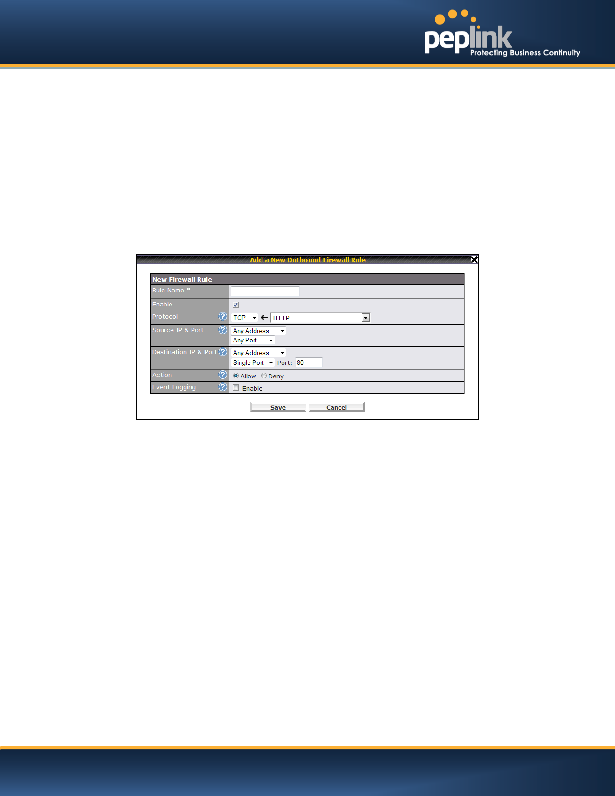
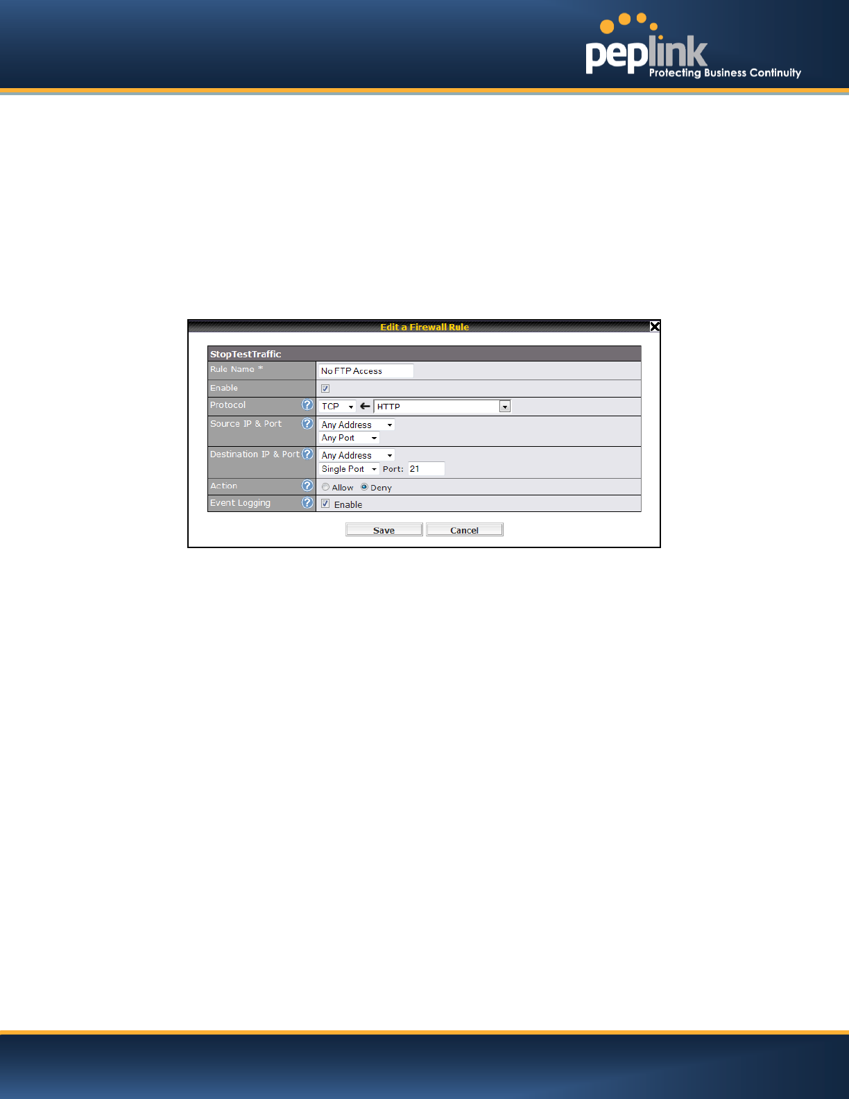
C.5 Outbound Access Restriction
C.5.1 Scenario
For security reasons, it may be appropriate to restrict outbound access. For example, you may want to
prevent LAN usersfrom usingftp to transfer files to and from the Internet.
This can easily be achieved by setting up an outbound firewall rule with Peplink Balance.
C.5.2 Solution
To setup a firewall between Internet and private network for outbound access, navigate to Network >
Access Rules. Afterwards, click the Add Rulebutton in the Outbound Firewall Rulestable, and then
follow the settings according the screenshot:
After the fields have been entered as in the screenshot, click Save to add the rule. Click Apply Changes
on the top right corner to complete the process.

USER MANUAL
Peplink Balance Series
http://www.peplink.com -215 / 227 - Copyright © 2014 Peplink
Appendix D. Troubleshooting
Problem 1
Outbound load is only distributed over one WAN connection.
Solution
Outbound load balancing can only be distributetraffic evenly between available WAN connections if many
outbound connections are made. If there is only one user on the LAN and only one download session is
made from his/her browser, the WAN connections cannot be fully utilized.
For a single user, download management applications are recommended.The applications can split a file
into pieces and download the pieces simultaneously. Examples include:DownThemAll(Firefox Extension),
iGetter (Mac), etc.
If the outbound traffic is going across the SpeedFusionTM tunnel, (i.e. transferring a file to a VPN peer)the
bandwidth of all WAN connections will be bonded. In this case, all bandwidth will be utilized and a file will
be transferred across all available WAN connections.
For additional details, please refer to this FAQ:
http://www.peplink.com/knowledgebase/maximizing-your-wan-connections-without-speedfusion/
Problem 2
I am using a download manager program (e.g. Download Accelerator Plus,DownThemAll etc.) now. Why
is the download speed still only that of a single link?
Solution
First, check whether allWAN connections are up.
Second, ensure your download manager application has split the file into 3 parts or more.
It is also possible that all of 2 or even 3 download sessions were being distributed to the same link by
chance.
Problem 3
I am using some websites to lookup my public IP address, e.g. www.whatismyip.com.WhenIkeep
pressing the browser's Refresh button, the server almost always returns the same address.The IP
address supposed to be changing for every refresh
Solution
The web server has enabled the Keep Alive function, which ensures that you use the same TCP session
to query the server.
Try to test with a web site that does not enable Keep Alive.
For example, tryhttp://private.dnsstuff.com/tools/aboutyou.ch(This third-party web site is provided only for
reference.Peplink has no association with the site and does not guarantee the site's validity or availability.)
Problem 4
What can I do if I suspect a problem on my LAN connection?
Solution
You can test the LAN connection using Ping.
For example, if you are using DOS/Windows, at the Command Prompt, type:
ping 192.168.1.1
This pingsthe Peplink Balance device (provided that Peplink Balance device’s IP is 192.168.1.1) to test
whether the connection to Peplink Balance is OK.

USER MANUAL
Peplink Balance Series
http://www.peplink.com -216 / 227 - Copyright © 2014 Peplink
Problem 5
What can I do if I suspect a problem on my Internet/WAN connection?
Solution
You can test the WAN connection by Ping, which is similar to problem 4.
As we want to isolate the problems from the LAN, Ping will be performed from Peplink Balance. By using
the Ping/Tracerouteunder the tab Status of the Peplink Balance, you may able to find out the source of
problem.
Problem 6
When I upload files to a server via ftp, the transfer stalls after a few kilobytes of data are sent.What
should I do?
Solution
The Maximum Transmission Unit (MTU) or MSS setting may need to be adjusted.
By default, the MTU is set at 1440. Choose Auto for all of your WAN connections. If that does not solve
the problem, you can try the MTU 1492 if a connection is a DSL. If problem still persists, change the size
to progressive smaller values until your problem is resolved (e.g. 1462, 1440, 1420, 1400, etc).

USER MANUAL
Peplink Balance Series
http://www.peplink.com -217 / 227 - Copyright © 2014 Peplink
Appendix E. Product Specifications
E.1 Peplink Balance 20, 30 and 30 LTE
Routing
Flexible Custom Outbound Routing Policy
WAN Support
DHCP, PPPoE and Static IP
Outbound Link Load Balance
Device Management
Wizard & Menu Driven Web Management Interface over HTTP / HTTPS
Remote Reporting and Management
Configurations Upload and Download
Internet Access Sharing
SUA (Single User Account) / Multi-to-Multi NAT
NAT supports PAT (Port Address Translation)
Security
IPsec (Network-to-Network)
Compatible with IPsec and PPTP VPNPassthrough
Rules-based Stateful Firewall, with IP, Protocol, and Port filtering
Intrusion Detection System
Physical Interface
Two (Balance 20) / Three (Balance 30, 30 LTE) RJ-45 for an IEEE 802.3u 10/100/1000M WAN
Four RJ-45 for an IEEE 802.3ab 10/100/1000M LAN
Power Specification
DC Input 9-16V
Operating Environment
Kensington Lock Interface
Temperature: 0°C - 55°C
Humidity: 10% - 90% (non-condensing)

USER MANUAL
Peplink Balance Series
http://www.peplink.com -218 / 227 - Copyright © 2014 Peplink
E.2 Peplink Balance 210 and 310
Routing
Drop-in Mode and NAT
Flexible Custom Outbound Routing Policy
WAN Support
DHCP, PPPoE and Static IP
Inbound and Outbound Link Load Balance
Device Management
Wizard & Menu Driven Web Management Interface over HTTP / HTTPS
Remote Reporting and Management
Bandwidth Usage Monitor
Configurations Upload and Download
Internet Access Sharing
SUA (Single User Account) / Multi-to-Multi NAT
NAT supports PAT (Port Address Translation)
Security
PPTP VPN Server
IPsec (Network-to-Network)
Rules-based Stateful Firewall, with IP, Protocol, and Port filtering
Bandwidth Bonding SpeedFusionTM
VPN Encryption: 256-bit AES
Intrusion Detection System
Physical Interface (Balance 210 Hardware Revision 2)
Two RJ-45 for an IEEE 802.3u 10/100/1000M WAN
Four RJ-45 for an IEEE 802.3ab 10/100/1000M LAN
Physical Interface (Balance 310 Hardware Revision 2)
Three RJ-45 for an IEEE 802.3u 10/100/1000M WAN
Four RJ-45 for an IEEE 802.3ab 10/100/1000M LAN
Power Specification
DC Input 9-16V
Operating Environment
Temperature: 0°C - 65°C
Humidity: 10% - 90% (non-condensing)

USER MANUAL
Peplink Balance Series
http://www.peplink.com -219 / 227 - Copyright © 2014 Peplink
E.3 Peplink Balance 380
Routing
Drop-in Mode and NAT
Flexible Custom Outbound Routing Policy
WAN Support
DHCP, PPPoE and Static IP
Inbound and Outbound Link Load Balance
DeviceManagement
Wizard & Menu Driven Web Management Interface over HTTP / HTTPS
Remote Reporting and Management
Bandwidth Usage Monitor
Configurations Upload and Download
Internet Access Sharing
SUA (Single User Account) / Multi-to-Multi NAT
NAT supports PAT (Port Address Translation)
Security
PPTP VPN Server
IPsec (Network-to-Network)
Rules-based Stateful Firewall, with IP, Protocol, and Port filtering
Bandwidth Bonding SpeedFusionTM
VPN Encryption: 256-bit AES
Intrusion Detection System
Physical Interface (Balance 380 Hardware Revision 5)
Three RJ-45 for an IEEE 802.3ab 10/100M/1000M WAN
One RJ-45 for an IEEE 802.3ab 10/100M/1000M LAN
One RJ-45 Console / Serial Port
Power Specification
AC input 100-240V
Operating Environment
Temperature: 0°C - 40°C
Humidity: 10% - 90% (non-condensing)

USER MANUAL
Peplink Balance Series
http://www.peplink.com -220 / 227 - Copyright © 2014 Peplink
E.4 Peplink Balance 305
Routing
Drop-in Mode and NAT
Flexible Custom Outbound Routing Policy
WAN Support
DHCP, PPPoE and Static IP
Inbound and Outbound Link Load Balance
DeviceManagement
Wizard & Menu Driven Web Management Interface over HTTP / HTTPS
Remote Reporting and Management
Bandwidth Usage Monitor
Configurations Upload and Download
Internet Access Sharing
SUA (Single User Account) / Multi-to-Multi NAT
NAT supports PAT (Port Address Translation)
Security
PPTP VPN Server
IPsec (Network-to-Network)
Rules-based Stateful Firewall, with IP, Protocol, and Port filtering
VPN Encryption: 256-bit AES
Intrusion Detection System
Physical Interface
Three RJ-45 for an IEEE 802.3ab 10/100M/1000M WAN
One RJ-45 for an IEEE 802.3ab 10/100M/1000M LAN
One RJ-45 Console / Serial Port
Power Specification
AC input 100-240V
Operating Environment
Temperature: 0°C - 40°C
Humidity: 10% - 90% (non-condensing)

USER MANUAL
Peplink Balance Series
http://www.peplink.com -221 / 227 - Copyright © 2014 Peplink
E.5 Peplink Balance 380
Routing
Drop-in Mode and NAT
Flexible Custom Outbound Routing Policy
WAN Support
DHCP, PPPoE and Static IP
Inbound and Outbound Link Load Balance
DeviceManagement
Wizard & Menu Driven Web Management Interface over HTTP / HTTPS
Remote Reporting and Management
Bandwidth Usage Monitor
Configurations Upload and Download
Internet Access Sharing
SUA (Single User Account) / Multi-to-Multi NAT
NAT supports PAT (Port Address Translation)
Security
PPTP VPN Server
IPsec (Network-to-Network)
Rules-based Stateful Firewall, with IP, Protocol, and Port filtering
Bandwidth Bonding SpeedFusionTM
VPN Encryption: 256-bit AES
Intrusion Detection System
Physical Interface (Balance 380 Hardware Revision 5)
Three RJ-45 for an IEEE 802.3ab 10/100M/1000M WAN
One RJ-45 for an IEEE 802.3ab 10/100M/1000M LAN
One RJ-45 Console / Serial Port
Power Specification
AC input 100-240V
Operating Environment
Temperature: 0°C - 40°C
Humidity: 10% - 90% (non-condensing)

USER MANUAL
Peplink Balance Series
http://www.peplink.com -222 / 227 - Copyright © 2014 Peplink
E.6 Peplink Balance 580
Routing
Drop-in Mode and NAT
Flexible Custom Outbound Routing Policy
WAN Support
DHCP, PPPoE and Static IP
Inbound and Outbound Link Load Balance
DeviceManagement
Wizard & Menu Driven Web Management Interface over HTTP / HTTPS
Remote Reporting and Management
Bandwidth Usage Monitor
Configurations Upload and Download
Internet Access Sharing
SUA (Single User Account) / Multi-to-Multi NAT
NAT supports PAT (Port Address Translation)
Security
PPTP VPN Server
IPsec (Network-to-Network)
Rules-based Stateful Firewall, with IP, Protocol, and Port filtering
Bandwidth Bonding SpeedFusionTM
VPN Encryption: 256-bit AES
Intrusion Detection System
Physical Interface
FiveRJ-45 for an IEEE 802.3ab 10/100M/1000M WAN
One RJ-45 for an IEEE 802.3ab 10/100M/1000M LAN
One RJ-45 Console / Serial (modem / TA) Port
LAN Bypass from WAN5 to LAN
Power Specification
AC input 100-240V
Operating Environment
Temperature: 0°C - 40°C
Humidity: 10% - 90% (non-condensing)

USER MANUAL
Peplink Balance Series
http://www.peplink.com -223 / 227 - Copyright © 2014 Peplink
E.7 Peplink Balance 710
Routing
Drop-in Mode and NAT
Flexible Custom Outbound Routing Policy
WAN Support
DHCP, PPPoE and Static IP
Inbound and Outbound Link Load Balance
DeviceManagement
Wizard & Menu Driven Web Management Interface over HTTP / HTTPS
Remote Reporting and Management
Bandwidth Usage Monitor
Configurations Upload and Download
Internet Access Sharing
SUA (Single User Account) / Multi-to-Multi NAT
NAT supports PAT (Port Address Translation)
Security
PPTP VPN Server
IPsec (Network-to-Network)
Rules-based Stateful Firewall, with IP, Protocol, and Port filtering
Bandwidth Bonding SpeedFusionTM
VPN Encryption: 256-bit AES
Intrusion Detection System
Physical Interface
Seven RJ-45 for an IEEE 802.3ab 10/100/1000M WAN
One RJ-45 for an IEEE 802.3ab 10/100/1000M LAN
One RJ-45 Console / Serial Port
Power Specification
AC input 100-240V
Operating Environment
Temperature: 0°C - 40°C
Humidity: 10% - 90% (non-condensing)

USER MANUAL
Peplink Balance Series
http://www.peplink.com -224 / 227 - Copyright © 2014 Peplink
E.8 Peplink Balance 1350
Routing
Drop-in Mode and NAT
Flexible Custom Outbound Routing Policy
WAN Support
DHCP, PPPoE and Static IP
Inbound and Outbound Link Load Balance
DeviceManagement
Wizard & Menu Driven Web Management Interface over HTTP / HTTPS
Remote Reporting and Management
Bandwidth Usage Monitor
Configurations Upload and Download
Internet Access Sharing
SUA (Single User Account) / Multi-to-Multi NAT
NAT supports PAT (Port Address Translation)
Security
PPTP VPN Server
IPsec (Network-to-Network)
Rules-based Stateful Firewall, with IP, Protocol, and Port filtering
Bandwidth Bonding SpeedFusionTM
VPN Encryption: 256-bit AES
Intrusion Detection System
Physical Interface
ThirteenRJ-45 for an IEEE 802.3ab 10/100/1000M WAN
One RJ-45 for an IEEE 802.3ab 10/100/1000M LAN
One RJ-45 Console / Serial (modem / TA) Port
LAN Bypass from WAN1 to LAN
Power Specification
AC input 100-240V
Operating Environment
Temperature: 0°C - 40°C
Humidity: 10% - 90% (non-condensing)

USER MANUAL
Peplink Balance Series
http://www.peplink.com -225 / 227 - Copyright © 2014 Peplink
E.9 Peplink Balance 2500
Routing
Drop-in Mode and NAT
Flexible Custom Outbound Routing Policy
WAN Support
DHCP, PPPoE and Static IP
Inbound and Outbound Link Load Balance
DeviceManagement
Wizard & Menu Driven Web Management Interface over HTTP / HTTPS
Remote Reporting and Management
Bandwidth Usage Monitor
Configurations Upload and Download
Internet Access Sharing
SUA (Single User Account) / Multi-to-Multi NAT
NAT supports PAT (Port Address Translation)
Security
PPTP VPN Server
IPsec (Network-to-Network)
Rules-based Stateful Firewall, with IP, Protocol, and Port filtering
Bandwidth Bonding SpeedFusionTM
VPN Encryption: 256-bit AES
Intrusion Detection System
Physical Interface
Twelve RJ-45 for an IEEE 802.3ab 10/100/1000M WAN
Eight RJ-45 for an IEEE 802.3ab 10/100/1000M LAN /Two SFP+ for an IEEE 802.3ae 10G LAN
One RJ-45 Console / Serial Port
Power Specification
AC input 100-240V
Operating Environment
Temperature: 0°C - 40°C
Humidity: 10% - 90% (non-condensing)

USER MANUAL
Peplink Balance Series
http://www.peplink.com -226 / 227 - Copyright © 2014 Peplink
Appendix F. Declaration
1. CAUTION:
RISK OF EXPLOSION IF BATTERY IS REPLACED BY AN INCORRECT TYPE.
DISPOSE OF USED BATTERIES ACCORDING TO THE INSTRUCTIONS
2. Federal Communication Commission Interference Statement
This device complies with Part 15 of the FCC Rules. Operation is subject to the following two conditions:
(1) This device may not cause harmful interference, and (2) this device must accept any interference
received, including interference that may cause undesired operation.
This equipment has been tested and found to comply with the limits for a Class B digital device, pursuant
to Part 15 of the FCC Rules. These limits are designed to provide reasonable protection against harmful
interference in a residential installation. This equipment generates, uses and can radiate radio frequency
energy and, if not installed and used in accordance with the instructions, may cause harmful interference
to radio communications. However, there is no guarantee that interference will not occur in a particular
installation. If this equipment does cause harmful interference to radio or television reception, which can
be determined by turning the equipment off and on, the user is encouraged to try to correct the
interference by one of the following measures:
- Reorient or relocate the receiving antenna.
- Increase the separation between the equipment and receiver.
- Connect the equipment into an outlet on a circuit different from that to which the receiver is connected.
- Consult the dealer or an experienced radio/TV technician for help.
FCC Caution: Any changes or modifications not expressly approved by the party responsible for
compliance could void the user's authority to operate this equipment.
This transmitter must not be co-located or operating in conjunction with any other antenna or transmitter.
3. Radiation Exposure Statement (for Balance One):
This equipment complies with FCC radiation exposure limits set forth for an uncontrolled environment.
This equipment should be installed and operated with minimum distance 22cm between the radiator &
your body.
Note: The country code selection is for non-US model only and is not available to all US model. Per FCC
regulation, all WiFi product marketed in US must fixed to US operation channels only.
Contact Address:
United States Office
800 West El Camino Real,
Mountain View
CA 94040
United States
Tel: +1 (650) 450 9668
Fax: +1 (866) 625 4664
Hong Kong Office
A5, 5/F, HK Spinners
Industrial Building, Phase 6,
481 Castle Peak Road,
Cheung Sha Wan, Hong
Kong
Tel: +852 2990 7600
Fax: +852 3007 0588
Italy Office
Via Sismondi 50/3
20133 Milan
Italy
Tel: +39 02 8986 6852
Saudi Arabia Office
3/F, Saudi Business Center,
Jeddah,
Saudi Arabia
Tel: +39 02 8986 6852
Contact Us:
Sales
http://www.peplink.com/contact/sales/
Support
http://www.peplink.com/contact/
Certified Peplink Partner
http://www.peplink.com/partners/chann
el-partner-program/
Difficulties when configuring the device?
Visit our YouTube Channel!
http://www.youtube.com/PeplinkChannel
Want to know more about us?
Add us on Facebook!
http://www.facebook.com/peplink
What are we doing at the moment?
Follow us on Twitter!
http://twitter.com/Peplink
Anything want to share with everyone?
Discuss on Peplink Forum!
http://forum.peplink.com
South Africa Office
Unit 24, Cambridge Office
Park,5 Bauhinia Street,
Highveld, Centurion,
South Africa
Tel: +27 12 665 5829