POINTER TELOCATION NANO3G CelloTrack Nano 20 3G P/N GC9771004-000 User Manual PowerPoint Presentation
Pointer Telocation CelloTrack Nano 20 3G P/N GC9771004-000 PowerPoint Presentation
UserManual.wiki
>
POINTER TELOCATION
>
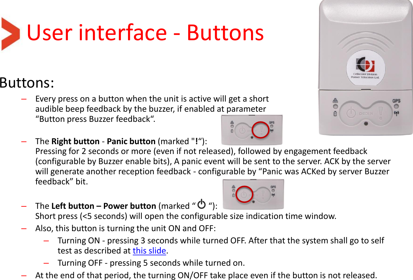
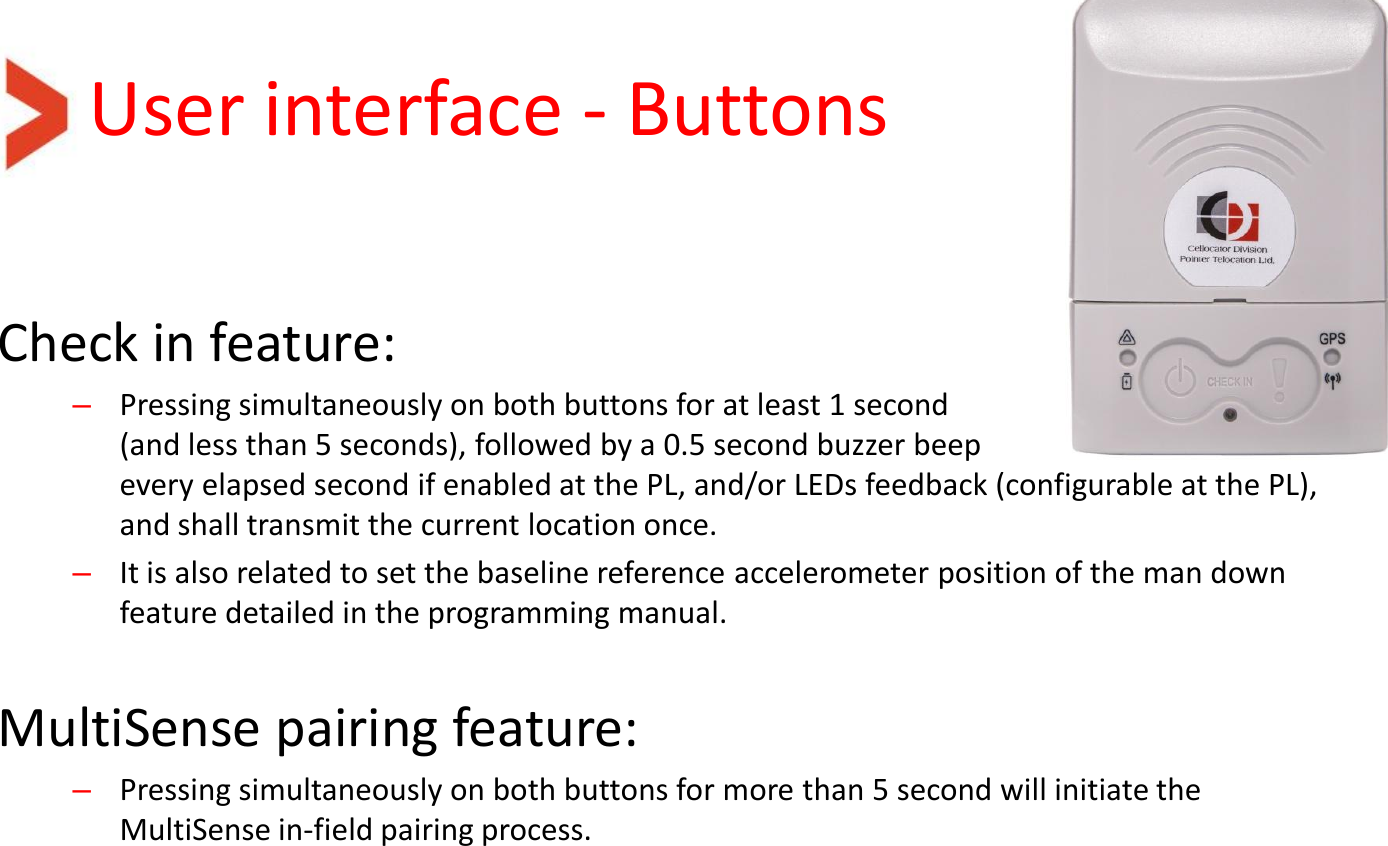
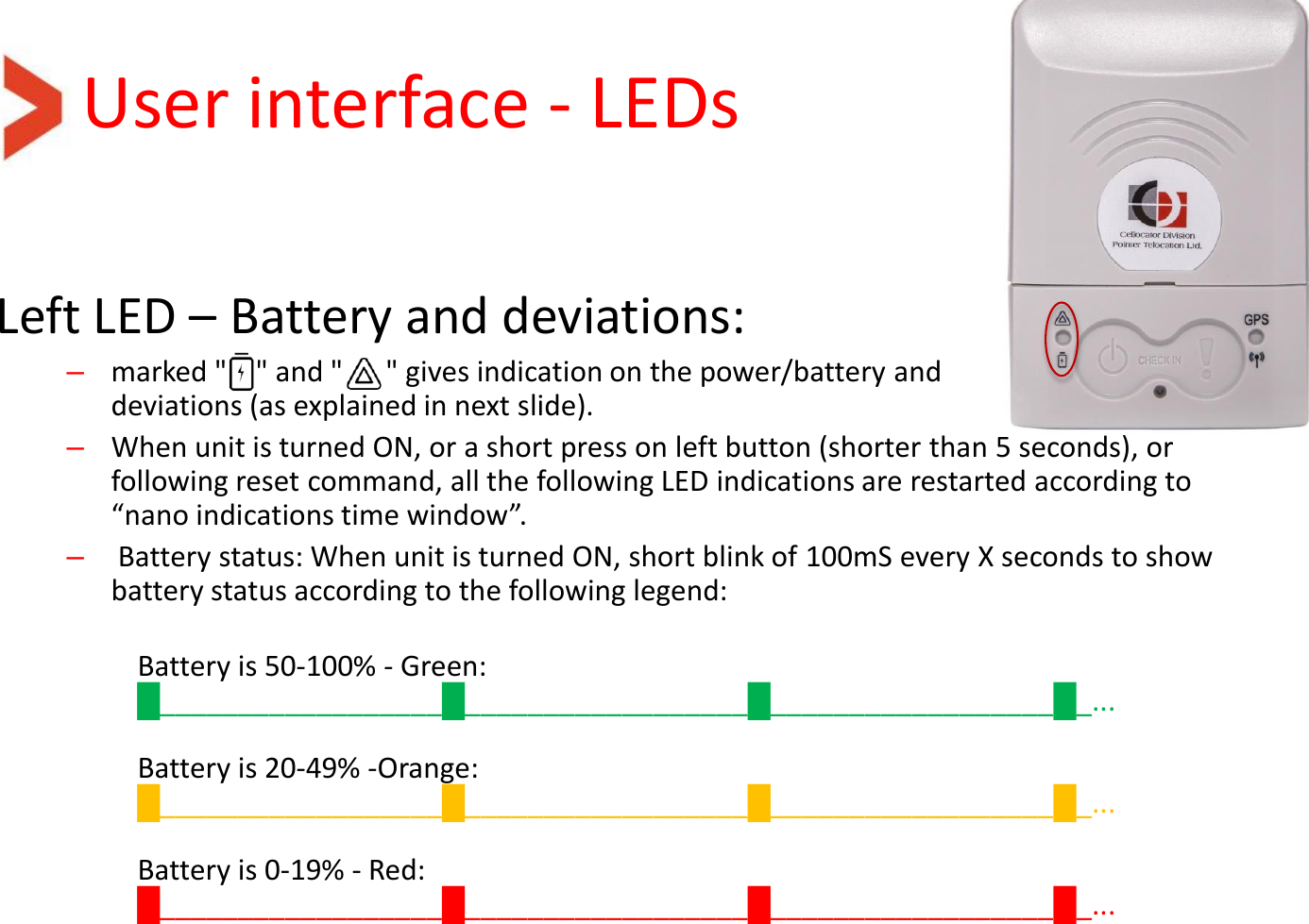
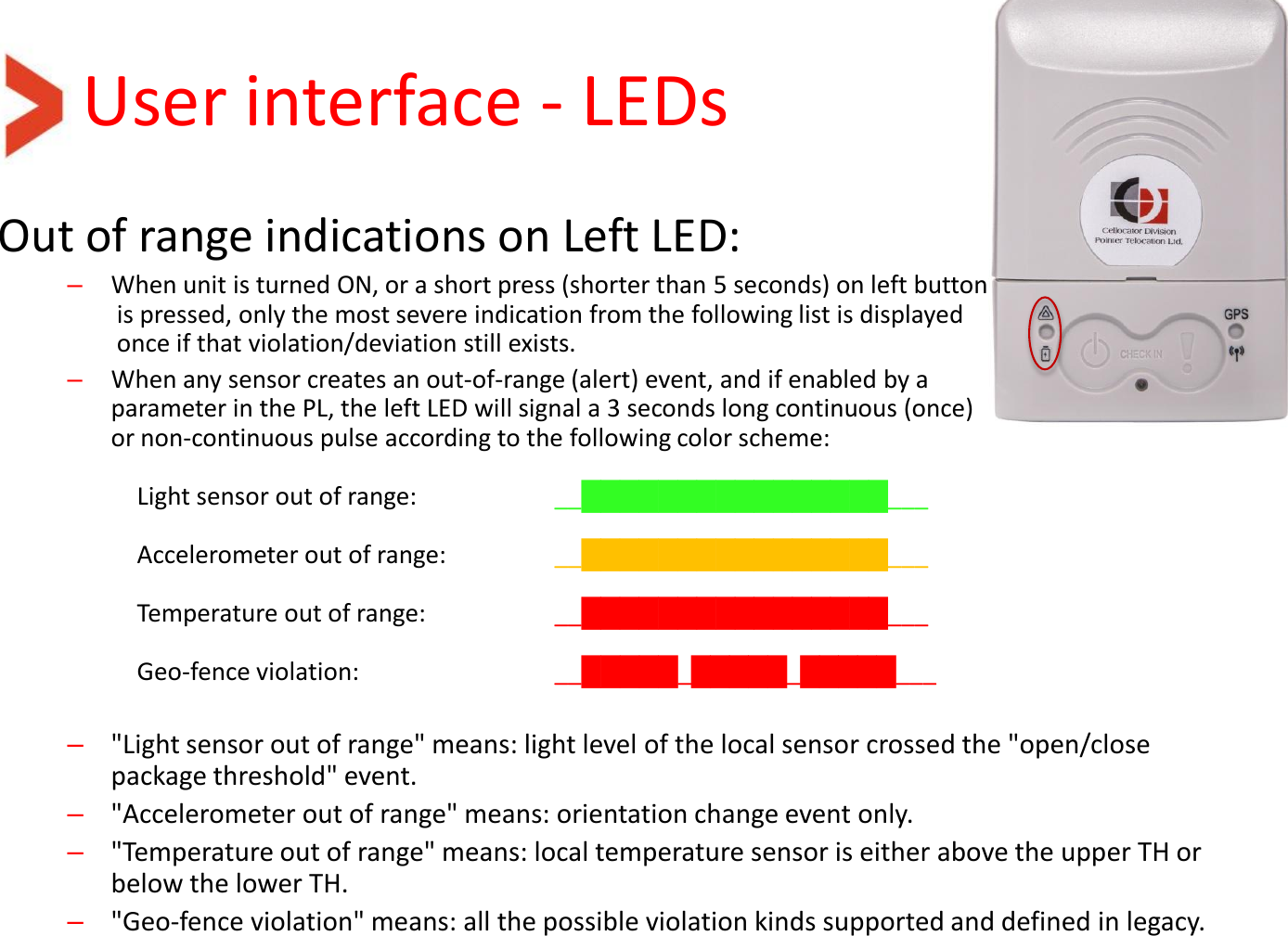
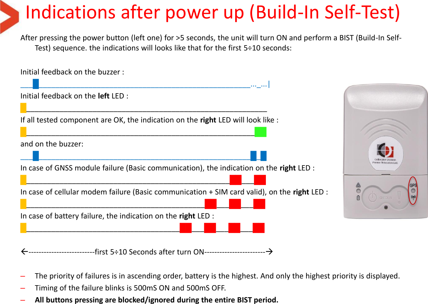
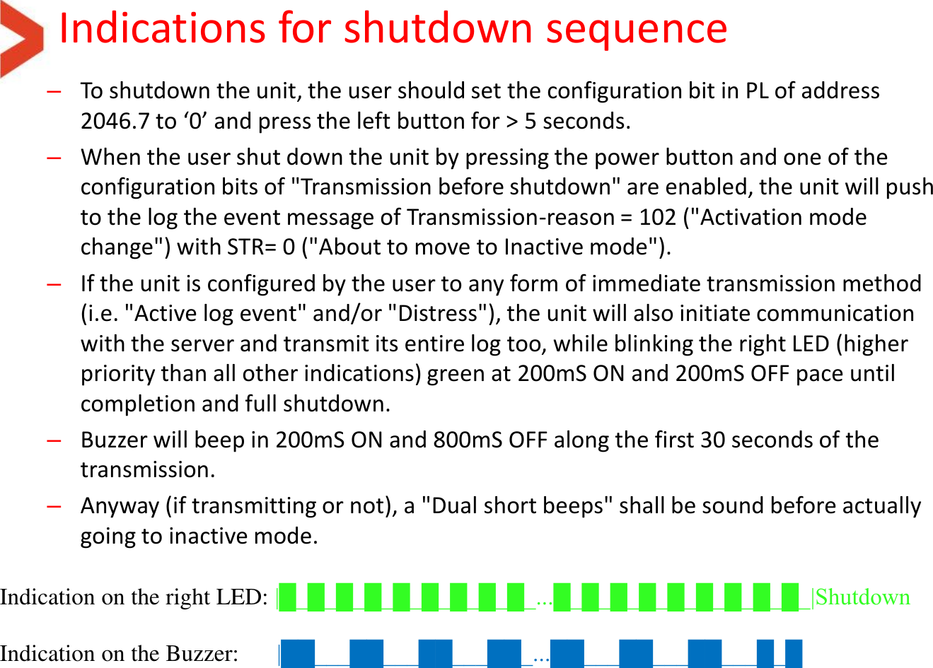
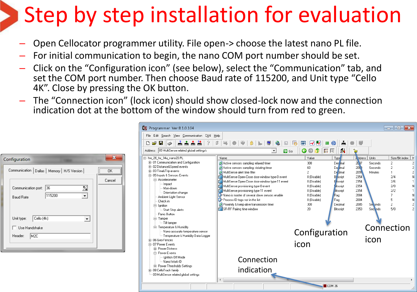
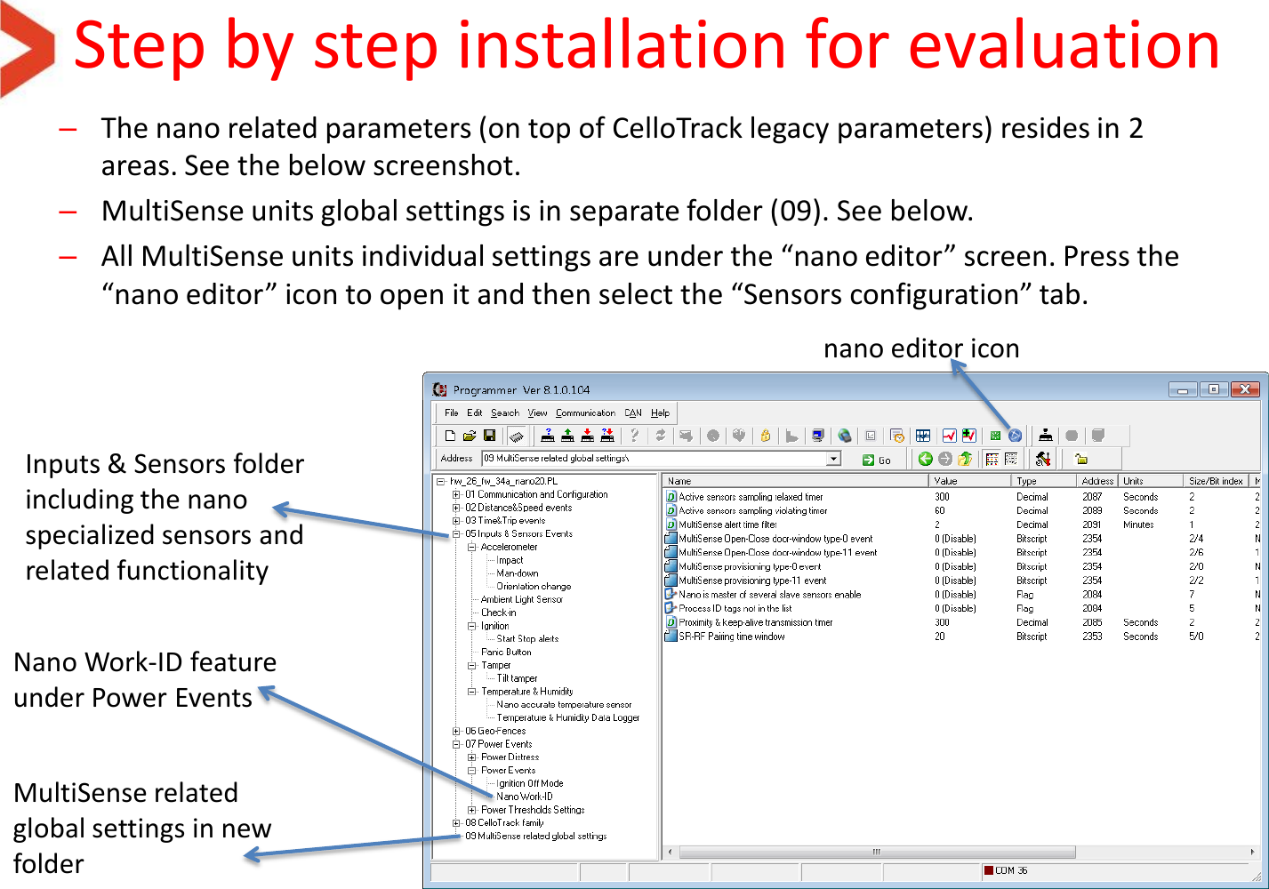
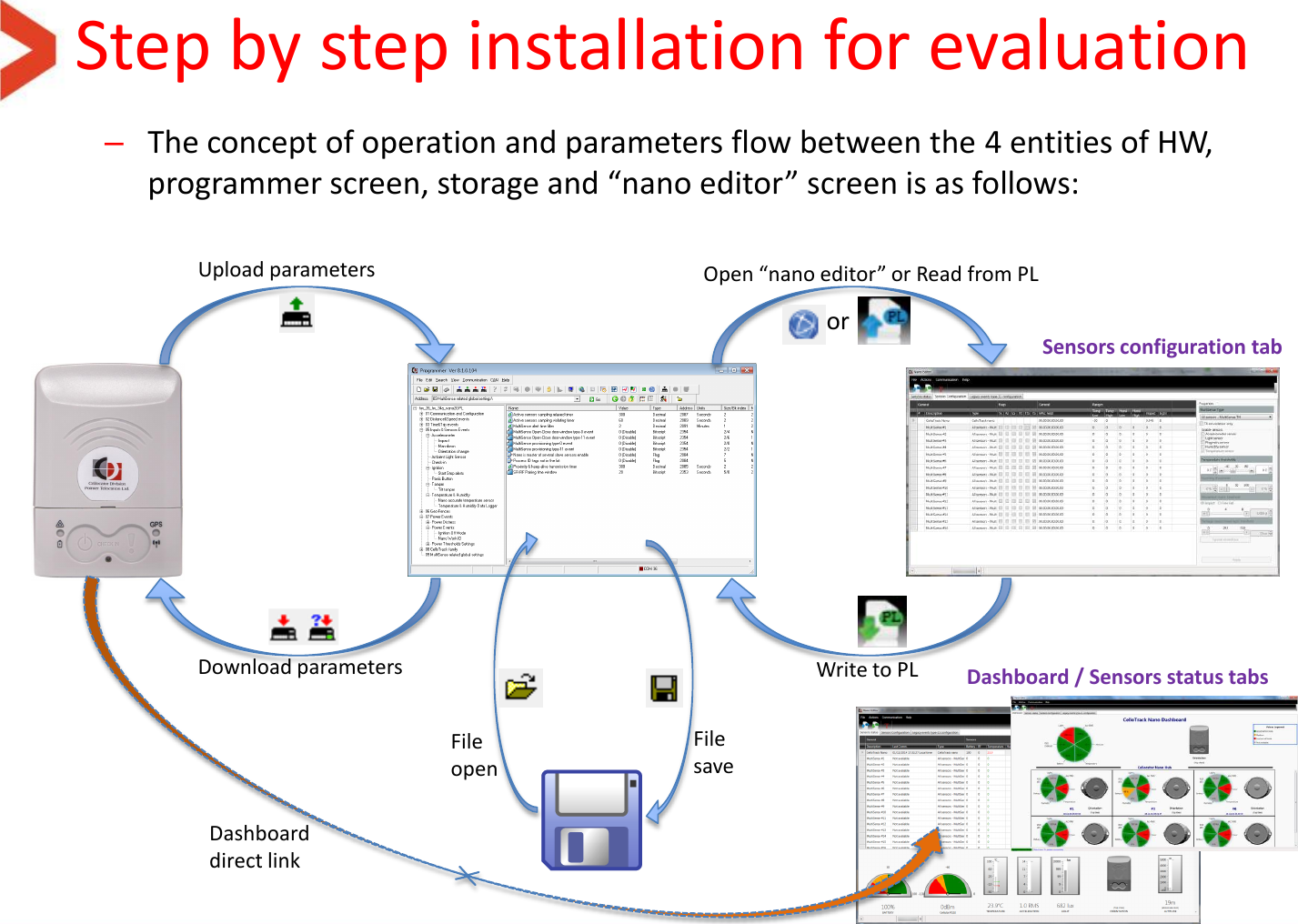
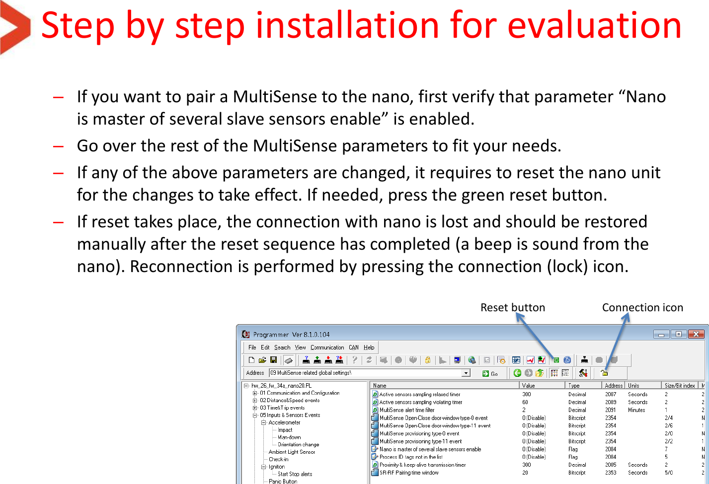
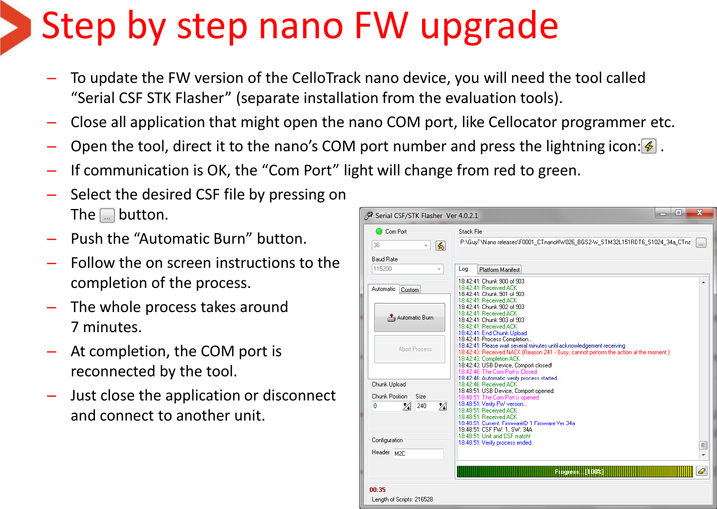
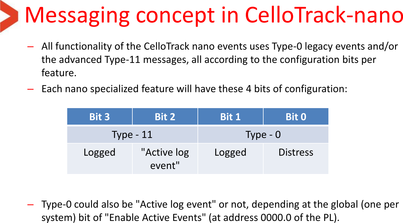
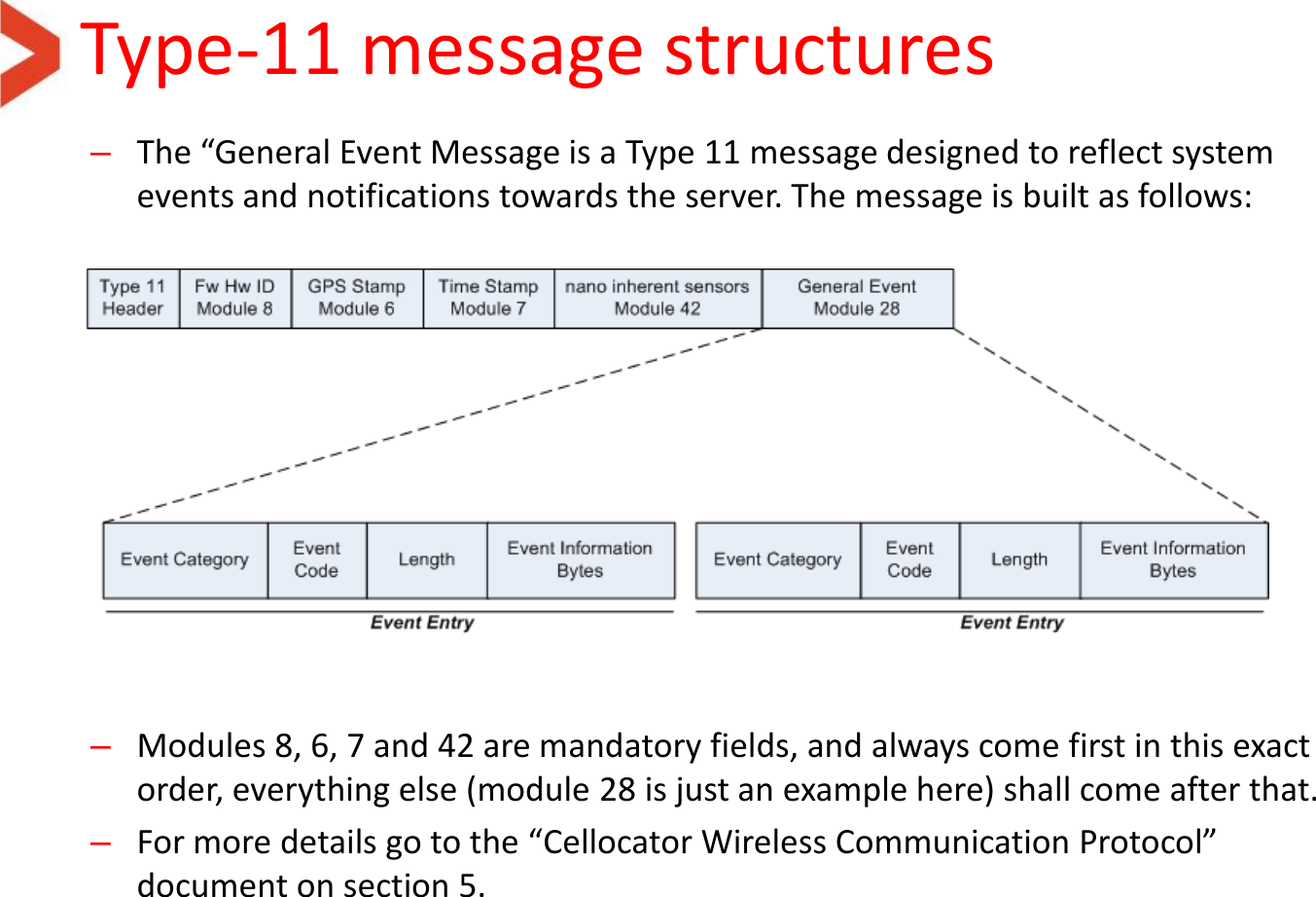
NANO3G User Manual
Users Manual
Navigation menu
Upload a User Manual
Namespaces
Wiki Guide
HTML
PDF
Info
Views
User Manual
Discussion / Help
Navigation