POINTER TELOCATION NANO3G CelloTrack Nano 20 3G P/N GC9771004-000 User Manual PowerPoint Presentation
Pointer Telocation CelloTrack Nano 20 3G P/N GC9771004-000 PowerPoint Presentation
Users Manual

CelloTrack Nano
and MultiSense
User Guide
V3.1 5-Oct-2016
16 PAIRD
MULTISENSE DUAL
TAMPERING
WIRELESS
SENSORS NETWORK VARIED APPS
App
SOUND TEMPERATURE LIGHT MOVEMENT PRESURE
INTERNAL
SENSORS
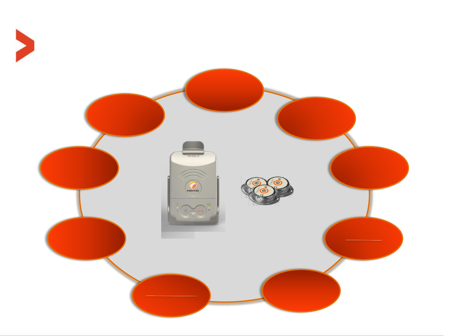
CELLOTRACK NANO
CelloTrack nano
Cargo and light asset management

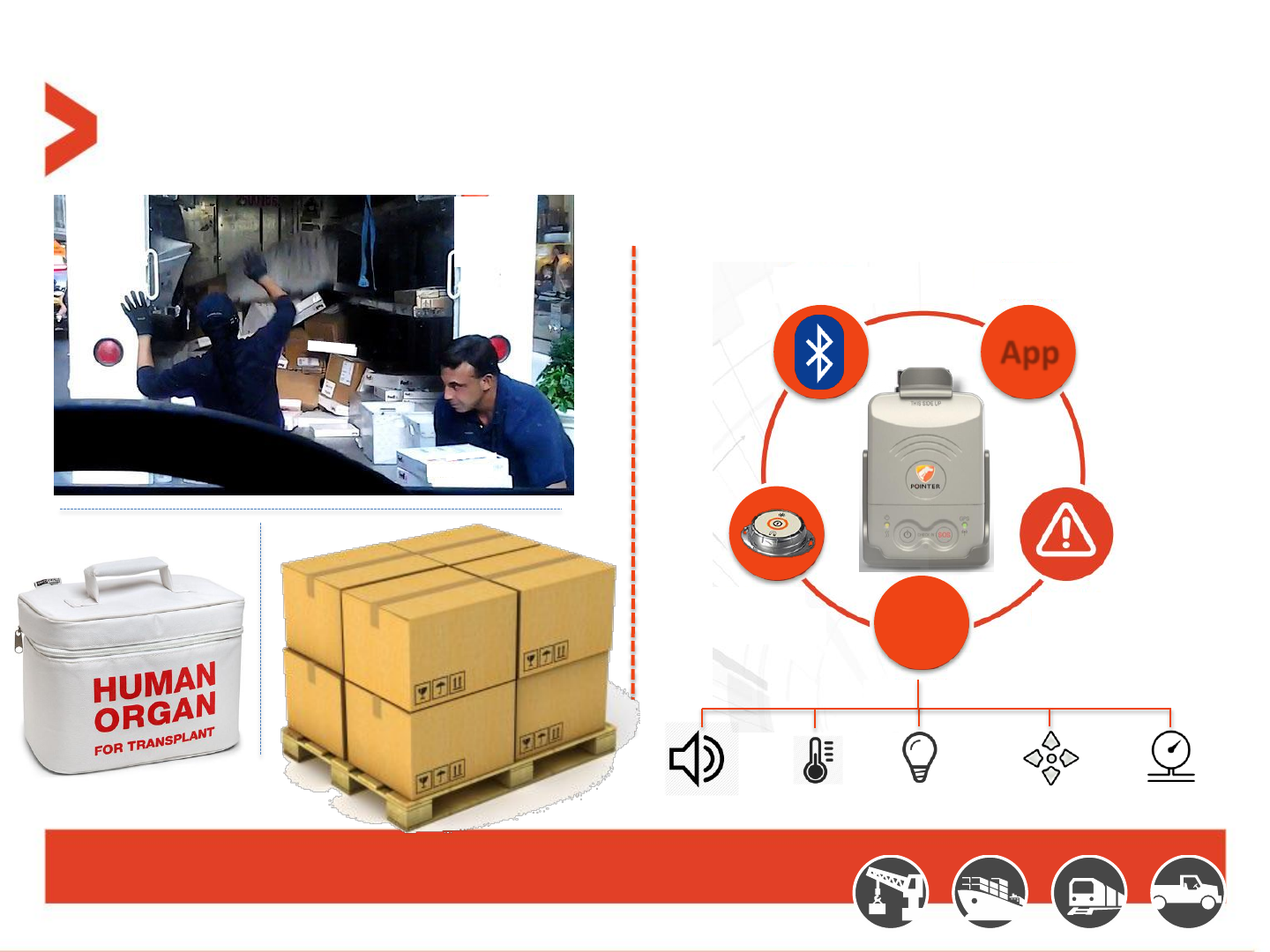
CelloTrack Nano Delivers
Real Time Cargo & Asset Visibility, Efficiency and Security
•Visibility
Enables real-time awareness of cargo and asset location, condition, problems and delays
using a portable gateway and short range Wireless Sensor Network (WSN).
•Efficiency
Ensures continuous recording, event-triggered logic and ‘management by exceptions’
through flexible programming of business rules to avoid supply chain mistakes, delays or
damages and to lower insurance expenses.
•Security
Prevents losses due to theft, loss and misplacement using proximity, tampering and
location sensing throughout the entire transport chain.
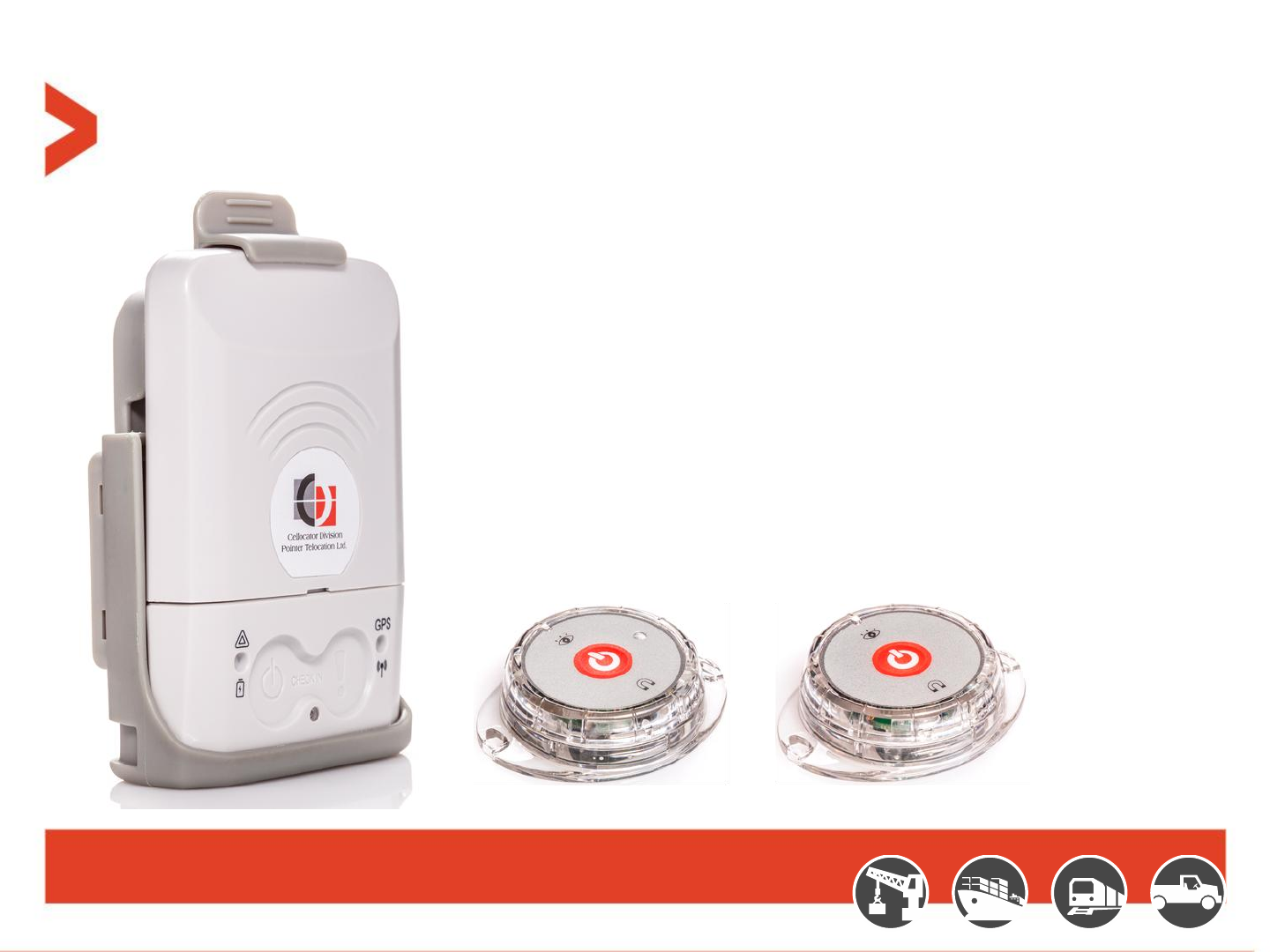
CelloTrack Nano
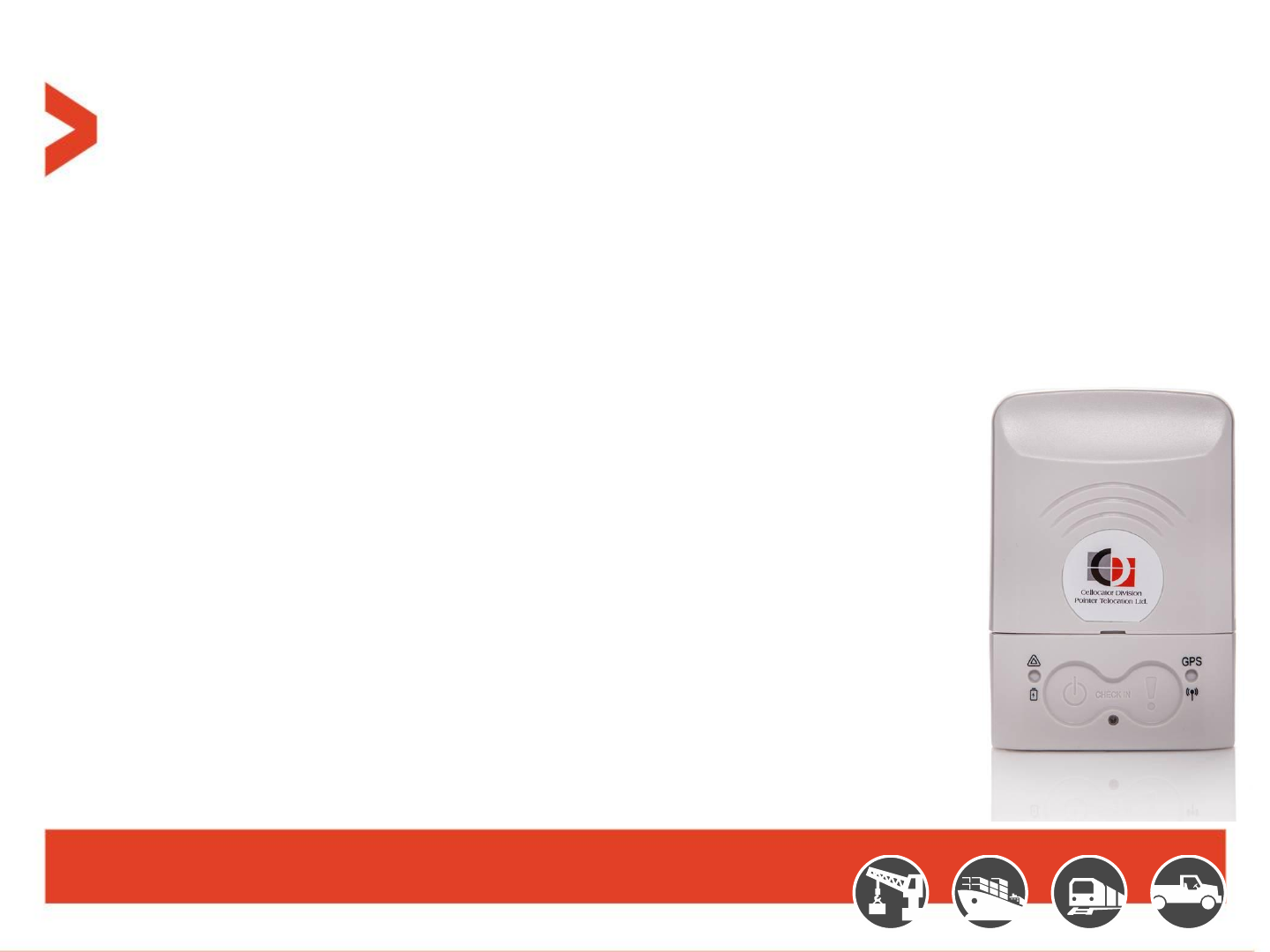
CelloTrack Nano™ Hub
Innovative, Smart and Compact asset monitoring device:
–SiRFstarV inside: multi GNSS (GPS, Glonass) with AGPS support (at 2nd phase)
–Internal sensors: temperature, light, impact, movement, pressure, sound (microphone)
–Used as a hub for a Wireless Sensor Network via BLE interface
–2G/3G communication to back-office application
–Advanced MMI: buzzer, status LEDs, multi-function buttons
–Low profile / compact and slick design (85x60x23mm, 94 gram)
–Dual Tampering detection
–Long life rechargeable Li-ion battery (up to 5 weeks of transport chain
usage)
–Micro USB connector for recharging the battery
–OTA update for Firmware and configuration
–IP 66 (dust and water jets), UV and chemicals protected
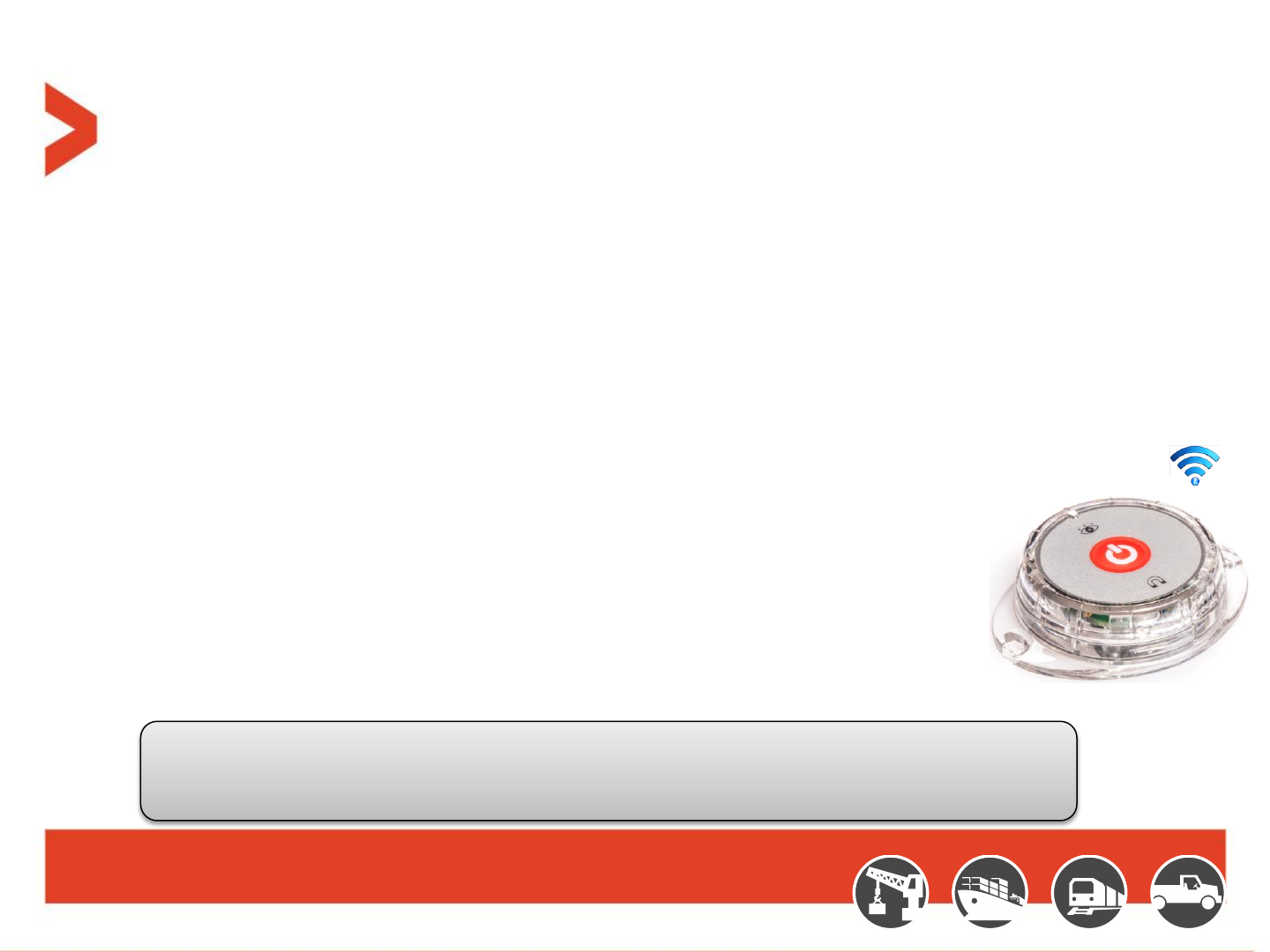
MultiSense Devices
A game changer in remote cargo & asset monitoring applications:
•Small, low cost device with rich embedded sensing capabilities:
–Temperature
–Humidity
–Movement
–Free Fall
–Impact
–Light
–Open/Close door/window
•BLE communication forms a cost effective Wireless Network with the Nano
•Long battery life for more than 1 year in common use case scenarios
•Easy battery replacement access (CR2450)
•Simple pairing with CelloTrack Nano
•On/Off Button
•LED indication for power on/off
•Small dimension (58.5 x 46 x 15mm, 26g including battery) and IP 67 enclosure
While paired with CelloTrack Nano, MultiSense provides a wireless sensing capability to a remote
location/facility where a wired interface is impractical. A Number of low cost MultiSense devices with
Nano GW dramatically reduces system’s TCO and improves monitoring efficiency

Solution Overview
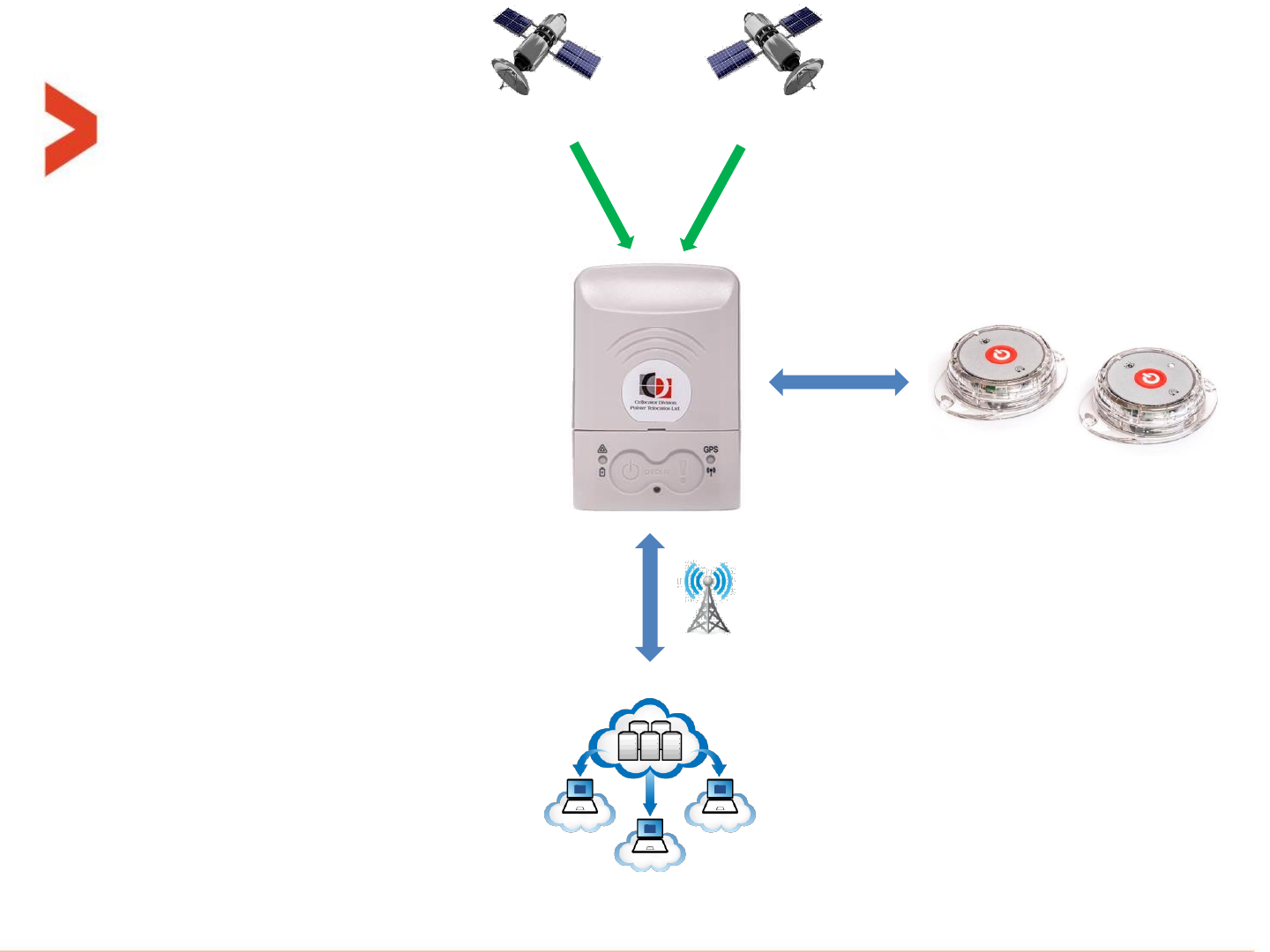
MultiSense
GPS GLONASS
CelloTrack Nano BLE
GSM
Remote Management
Temperature
Humidity
Free Fall
Impact
Light
Open/Close Door
Smart Gateway
Up to 16 MultiSense
Location
SOS
Check In / Check out
Temperature
Free Fall
Barometric pressure
Impact
Light
Dual tamper
Multi-functional cradle
Temperature
Humidity
(MultiSense)
Barometric
Pressure
(Nano)
Light
Open/Close
Door
(MultiSense)
Free Fall
Impact
Geo Fencing
(Nano)
Tampering
Proximity
Movement
Multi Sensors


System Operation

CelloTrack nano terminology
–Active state = ON state = Unit is turned ON
–Inactive state = OFF state = Unit is turned OFF (the lowest power consumption)
–“Indications time window” = the time window that the LEDs and buzzer are active. After
that time, they are shut down to save energy. This window opens after power up, reset
and pressing one of the buttons. This size of this window is configurable.
–“Check-in” = A feature that when both buttons are pressed the unit sends it location with
a check-in transmission reason.
–MultiSense pairing = When the operator wants the nano to be connected/linked/paired
with a certain MultiSense unit, the nano and the MultiSense must first perform a pairing
process, where the nano register the MultiSense MAC address in one place of its 16 cells
table.
–BIST = Build-In Self-Test process, preformed after reset or power-up (battery connection).
–“Guest mode” = When this mode is enabled in the nano, it will communicate with any
MultiSense in its range, forwarding its sensors data to the server.
User interface - Buttons
Buttons overview table while the unit is in
active state:
Pressing Duration
Left button
Right button
Both
simultaneously
T < 200mS
Ignored
T > 200mS
Very short feedback from buzzer,
Open the indications time window
1 Sec > T > 200mS
-
-
Check-in event
2 Sec > T > 1 Sec
-
Check-in event
5 Sec > T > 2 Sec
Panic event
Check-in event
T > 5 Sec
Power-off unit
Panic event
MultiSense pairing
window open
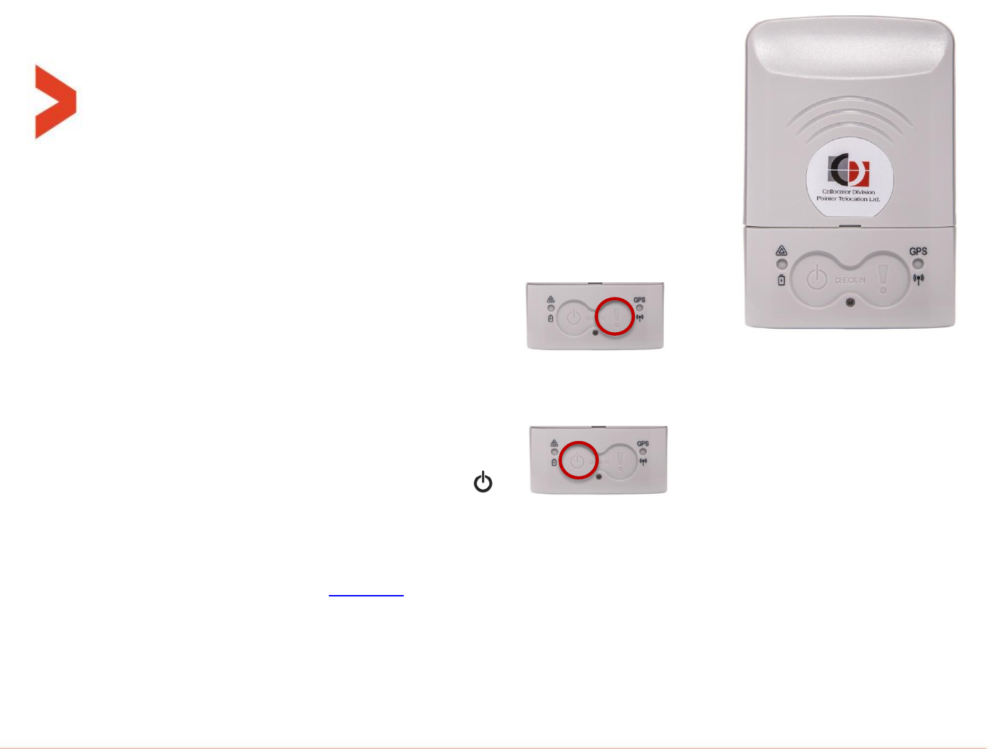
User interface - Buttons
Buttons:
–Every press on a button when the unit is active will get a short
audible beep feedback by the buzzer, if enabled at parameter
“Button press Buzzer feedback“.
–The Right button - Panic button (marked "!“):
Pressing for 2 seconds or more (even if not released), followed by engagement feedback
(configurable by Buzzer enable bits), A panic event will be sent to the server. ACK by the server
will generate another reception feedback - configurable by “Panic was ACKed by server Buzzer
feedback” bit.
–The Left button – Power button (marked “ “):
Short press (<5 seconds) will open the configurable size indication time window.
–Also, this button is turning the unit ON and OFF:
–Turning ON - pressing 3 seconds while turned OFF. After that the system shall go to self
test as described at this slide.
–Turning OFF - pressing 5 seconds while turned on.
–At the end of that period, the turning ON/OFF take place even if the button is not released.
User interface - Buttons
Check in feature:
–Pressing simultaneously on both buttons for at least 1 second
(and less than 5 seconds), followed by a 0.5 second buzzer beep
every elapsed second if enabled at the PL, and/or LEDs feedback (configurable at the PL),
and shall transmit the current location once.
–It is also related to set the baseline reference accelerometer position of the man down
feature detailed in the programming manual.
MultiSense pairing feature:
–Pressing simultaneously on both buttons for more than 5 second will initiate the
MultiSense in-field pairing process.
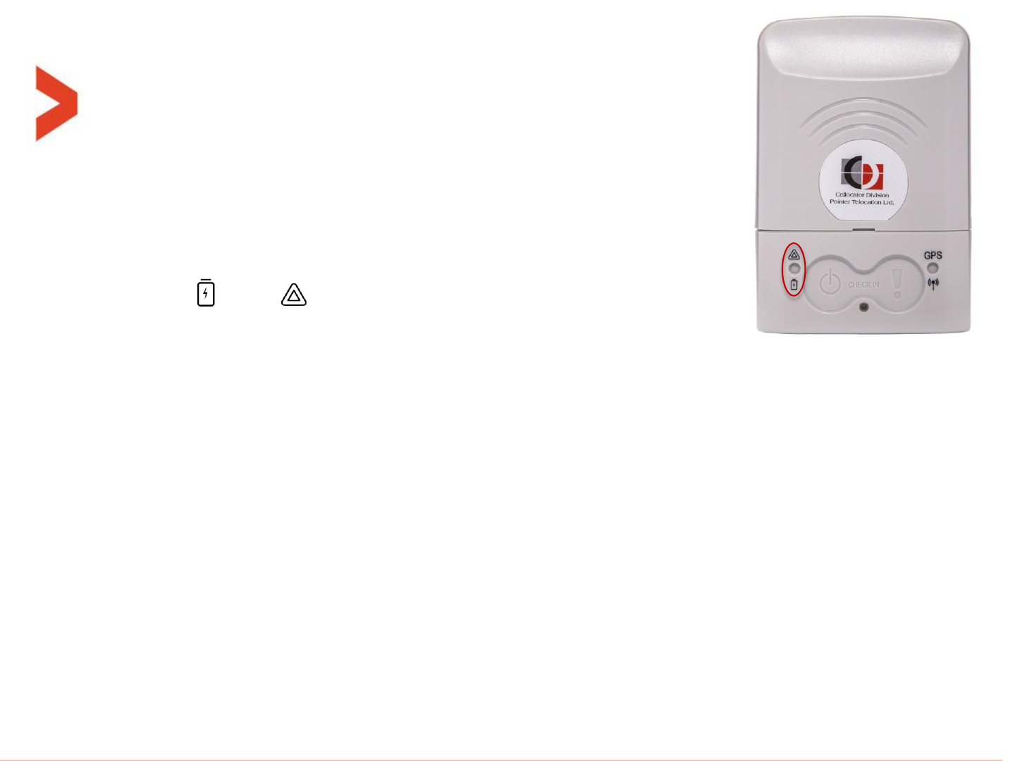
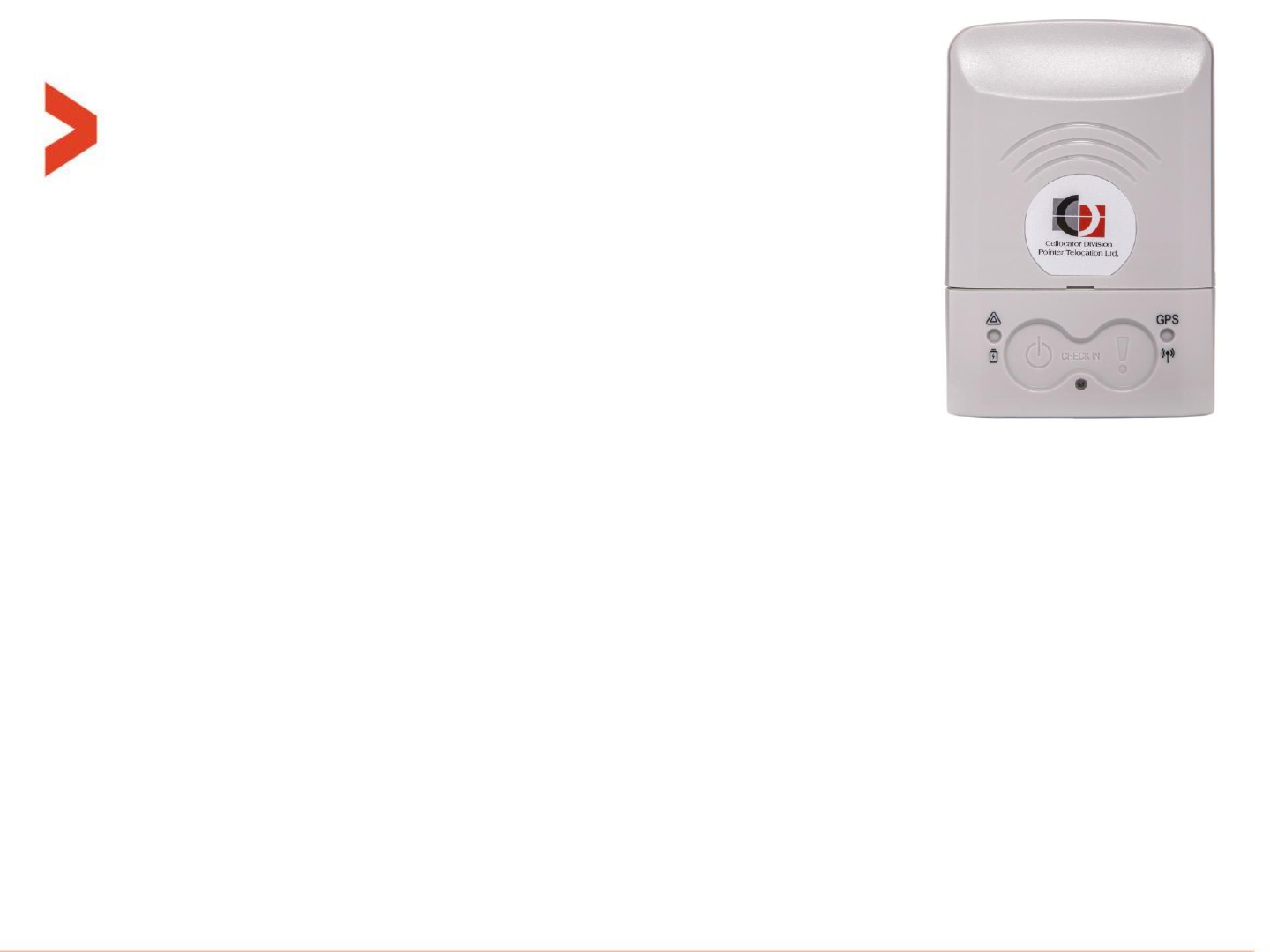
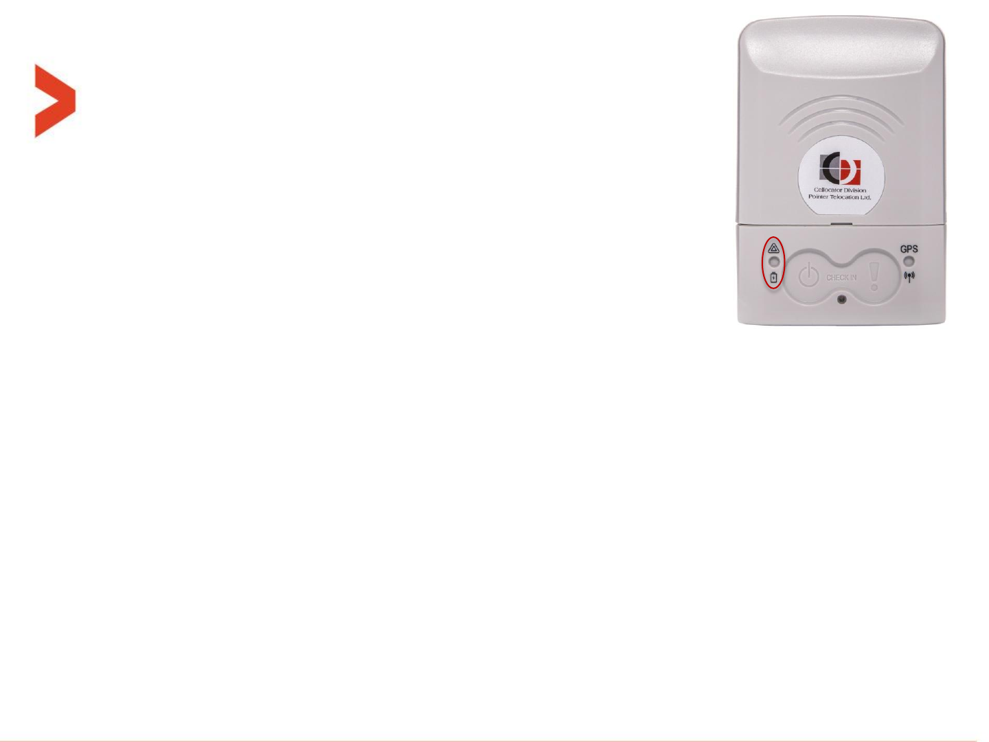
User interface - LEDs
Left LED – Battery and deviations:
–marked " " and " " gives indication on the power/battery and
deviations (as explained in next slide).
–When unit is turned ON, or a short press on left button (shorter than 5 seconds), or
following reset command, all the following LED indications are restarted according to
“nano indications time window”.
– Battery status: When unit is turned ON, short blink of 100mS every X seconds to show
battery status according to the following legend:
Battery is 50-100% - Green:
█__________________█__________________█__________________█_...
Battery is 20-49% -Orange:
█__________________█__________________█__________________█_...
Battery is 0-19% - Red:
█__________________█__________________█__________________█_...
User interface - LEDs
Out of range indications on Left LED:
–When unit is turned ON, or a short press (shorter than 5 seconds) on left button
is pressed, only the most severe indication from the following list is displayed
once if that violation/deviation still exists.
–When any sensor creates an out-of-range (alert) event, and if enabled by a
parameter in the PL, the left LED will signal a 3 seconds long continuous (once)
or non-continuous pulse according to the following color scheme:
Light sensor out of range: __████████████████___
Accelerometer out of range: __████████████████___
Temperature out of range: __████████████████___
Geo-fence violation: __█████_█████_█████___
–"Light sensor out of range" means: light level of the local sensor crossed the "open/close
package threshold" event.
–"Accelerometer out of range" means: orientation change event only.
–"Temperature out of range" means: local temperature sensor is either above the upper TH or
below the lower TH.
–"Geo-fence violation" means: all the possible violation kinds supported and defined in legacy.

User interface - LEDs
Charging indications on Left LED:
–When micro-USB connector is plugged-in and charging is in fact
in progress, whether from charger (AC wall adaptor) or PC, the
left LED will act as described in the table below:
–These indications have the highest priority and they override all other indications on this LED
Unit mode:
OFF (inactive)
ON (active)
During actual charging
Constantly
orange
Constantly
orange
After charge
completion
Inside the "Indications
time window"
Constantly
green
Regular LEDs
indications
After (outside) the
"Indications time
window"
Constantly
green
Battery Fault
Constantly red
Constantly red
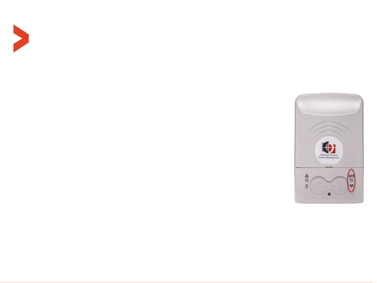
User interface - LEDs
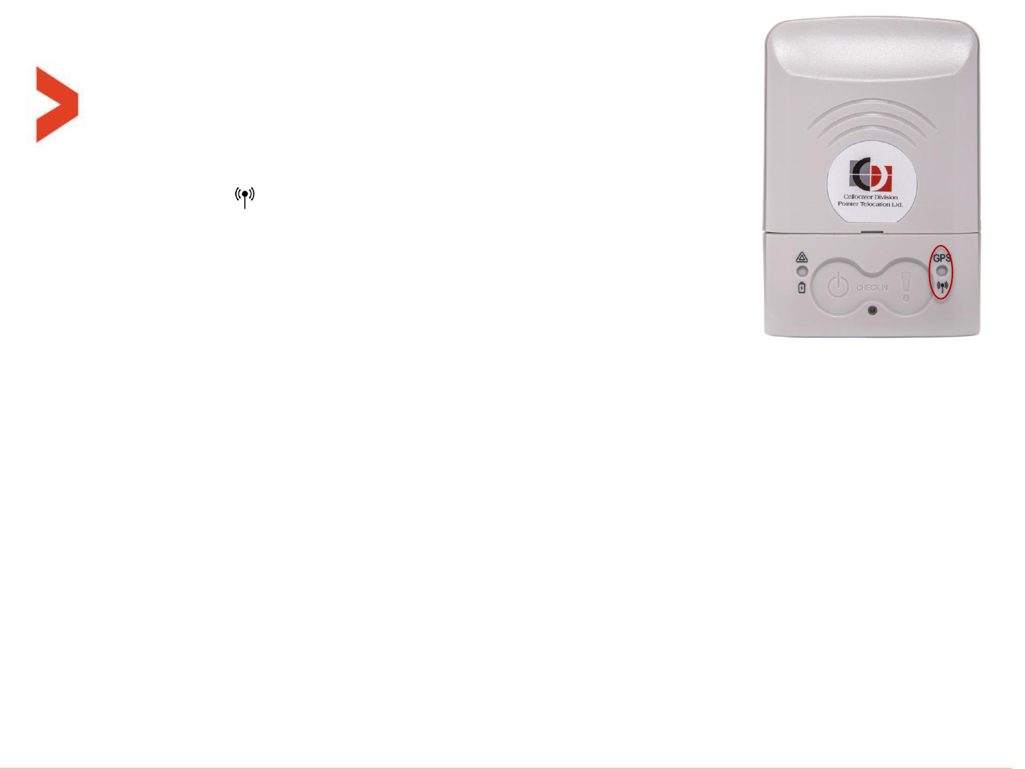
Right LED – Cellular/GPS status:
–marked "GPS" and " ".
–Two time slots of 5 seconds long each. The first one is for indications from cellular modem in green
and the second one is for GNSS module indications in orange.
–Each pulse is 500mS ON and 500mS OFF.
–Cellular modem indications:
HSDPA/HSUPA (3G) communication:
██________________________________________________________|
GPRS/EDGE communication:
██___██__________________________________________________|
Registered (GSM-2G):
██___██___██____________________________________________|
Not registered (no activated network found):
██___██___██___██______________________________________|
GNSS module indications:
Tracking good (Fix "Tight"):
██________________________________________________________|
Tracking poor (Fix "Plain"):
██___██__________________________________________________|
Acquisition (from power-up to "Plain" or "Tight") :
██___██___██____________________________________________|
No satellites at all ("no fix" after fix), only at the first operation and cannot be reached if using A-GPS:
██___██___██___██______________________________________|
For example the light for a GPRS communication and good tracking will look like that:
█_█___________________█______________________█_█___________________█__…
-------------5Sec------------
–All these indications are displayed only for the “nano indications time window" time. After that they are cleared and not displayed.

User interface - Buzzer
Buzzer types:
Buttons feedback beep = 20mS ON. |
Short beep = 200mS ON. ██
Dual short beeps = 200mS ON, 200mS OFF, 200mS ON. ██___██
Dual long beeps = 1 Sec ON, 200mS OFF, 1 Sec ON. █████████___█████████
Long beep = 2 Sec. ██████████████████
Buzzer logic:
–Upon power-up (turning ON) or system reset from any reason, short beep.
–After a successful BIST (Build-In Self-Test) process, dual short beeps.
If enabled in PL:
–Every valid pressing on buttons, will sound the "Buttons feedback beep" (20mS).
–Panic /Check-in event activation operates the beeps as explained in the programming manual.
–After Panic (special distress) event got acknowledged by the server, long beep.
–When any active sensors go out of the defined limits (all meanings of the "out-of-range" are explained
in the programming manual), plus geo-fences (all legacy violation related to geo-fences are relevant
here too), the unit shall sound short beeps every PL configurable time if the "Indications time window“
is open/active.
–Short beep upon any power-up packet received from a paired/preregistered MultiSense.
See SR-RF pairing (and un-pairing) process related beeps at this slide.

Indications after power up (Build-In Self-Test)
–The unit will perform a Build-In Self-Test (BIST) upon any of the
following cases:
1. When battery is connected, while system was active before
disconnection.
2. After turning ON (moving unit from inactive to active mode, at the
end of the 3 second press duration).
3. Upon receiving a reset command.
–The Build-In Self-Test (BIST) shall include GNSS module, Cellular modem
basic (local) communication + SIM exists and battery.
Indications after power up (Build-In Self-Test)
After pressing the power button (left one) for >5 seconds, the unit will turn ON and perform a BIST (Build-In Self-
Test) sequence. the indications will looks like that for the first 5÷10 seconds:
Initial feedback on the buzzer :
___█___________________________________________________..._...|
Initial feedback on the left LED :
█__________________________________________________________
If all tested component are OK, the indication on the right LED will look like :
█_______________________________________________________██
and on the buzzer:
___█___________________________________________________█_█
In case of GNSS module failure (Basic communication), the indication on the right LED :
█_________________________________________________██___██
In case of cellular modem failure (Basic communication + SIM card valid), on the right LED :
█___________________________________________██___██___██
In case of battery failure, the indication on the right LED :
█_____________________________________██___██___██___██
--------------------------first 5÷10 Seconds after turn ON------------------------
–The priority of failures is in ascending order, battery is the highest. And only the highest priority is displayed.
–Timing of the failure blinks is 500mS ON and 500mS OFF.
–All buttons pressing are blocked/ignored during the entire BIST period.

Indications for shutdown sequence
–To shutdown the unit, the user should set the configuration bit in PL of address
2046.7 to ‘0’ and press the left button for > 5 seconds.
–When the user shut down the unit by pressing the power button and one of the
configuration bits of "Transmission before shutdown" are enabled, the unit will push
to the log the event message of Transmission-reason = 102 ("Activation mode
change") with STR= 0 ("About to move to Inactive mode").
–If the unit is configured by the user to any form of immediate transmission method
(i.e. "Active log event" and/or "Distress"), the unit will also initiate communication
with the server and transmit its entire log too, while blinking the right LED (higher
priority than all other indications) green at 200mS ON and 200mS OFF pace until
completion and full shutdown.
–Buzzer will beep in 200mS ON and 800mS OFF along the first 30 seconds of the
transmission.
–Anyway (if transmitting or not), a "Dual short beeps" shall be sound before actually
going to inactive mode.
Indication on the right LED: |█_█_█_█_█_█_█_█_█_...█_█_█_█_█_█_█_█_█_|Shutdown
Indication on the Buzzer: |██___██___██___██_...██___██___██___█_█

USB and charging
Usage:
Micro-B female USB connector, through which the unit can perform the following functions:
–Charging the internal battery from the supplied AC-adaptor or PC USB port.
–USB port serial communication for PL update.
–USB port serial communication for FW upgrade.
Charging:
The CelloTrack battery operates on a Li-Ion battery of 1000mAh nominal capacity.
The internal changer supports 2 level of charging speeds:
–The slow speed is used when the unit recognizes the source as "weak". It could be
USB 1.0 PC port, weak AC-adaptors or weak car-adaptors.
–The charging current in this case is ~100mA so full charge time can sometimes be
more than 10 hours.
–The faster speed is automatically chosen when the source is recognized to be able to
supply enough current. Then the charging current in this case is ~330mA so full
charge time will be less than 5 hours.

USB and charging
Charging modes:
The unit has 2 modes of charging:
–FW controlled – the nano FW decide when to start and stop charging. It charges
the battery to a certain hardcoded high-level charge point (e.g. 90%) and then
let the battery be consumed to the level of an hardcoded low-level charge point
(e.g. 75%) before another charge cycle is started. In this way, the battery
oscillates between 90% and 75% forever and the left LED toggles between green
and yellow forever.
To set this mode, set the parameter of "Charging Stop upon Battery Full
detection" to "Stop charging".
This mode of operation is more suitable for constantly powered systems and it
keeps the battery health better in the long run.
–HW controlled – the charger chip decides when the battery has reached full
charge (100%) and then stops charging it. Indication on left LED turns then from
orange to green.
This operation is restarted every 5 hours.
To set this mode, set the parameter of "Charging Stop upon Battery Full
detection" to "Keep charging".
This mode is more suitable for systems that get charged from time to time, but
the system is not powered constantly.
MultiSense
Overview:
–The MultiSense is a remote peripheral sensor communicating and
configured by the CelloTrack-nano via a short-range RF link.
–There are 2 models of MultiSense: regular ones that can measure temperature called just
"MultiSense" and "MultiSense-TH" which have combined temperature + humidity sensor.
–The MultiSense unit has the following sensors on it:
1. Temperature sensor
2. Humidity sensor (only in MultiSense-TH model)
3. Hall effect magnetic sensor
4. Ambient Light Sensor (ALS)
5. Accelerometer sensor
–The system supports up to 16 fully programmable MultiSense units.
–If "guest mode" is enabled in the parameter “Process ID tags not in the list”, the nano unit
will also connect with MultiSense units not in its list, read their sensors and pass the data
(in raw format) to the server. Only listed MultiSense units also gets configuration block and
their readings are fully processed by the nano.

MultiSense
More information:
–The MultiSense is a configurable sleepy peripheral slave, which means it is
configurable by the tools (via the nano) and it transmits according to the
preconfigured policy.
–The nano, if enabled in parameter “Nano is master of several slave sensors
enable” is always listening to RF links and intercepts MultiSense units.
–The RF range between the MultiSense and nano unit can reach more than
100m at open space (optimal conditions), and lower in various installations. All
according to attenuation at 2.4GHz of the RF signal.
–If the MultiSense is not received by the nano for 5 x “Proximity & keep-alive
transmission timer” it will report it as lost. (could be due to: Dead battery, shut-
down, totally out-of-range or stolen).
–The battery of the MultiSense is the Lithium coin CR2450 (~600mAh) battery
and its lifetime depends heavily on its configuration. Typically several months.
–MultiSense units can be intercepted by an updated cellular phone* but data is
encrypted so it cannot be understood.
–The CelloTrack-nano cannot interface with other sensors in the market.

MultiSense
Transmission policy:
–All the MultiSense units related to a nano system has the same configuration of the following
timers:
1. Relaxed (R) – parameter in PL: “Active sensors sampling relaxed timer“. Used when
the temperature and humidity are within their (configurable) limits.
2. Violation(V) - parameter in PL: “Active sensors sampling violating timer“. Used when
the temperature and humidity are out of their (configurable) limits.
3. Proximity(P) - parameter in PL: “Proximity & keep-alive transmission timer”. Used all
the time independently from the previous ones.
–If "TX on violations only" mode is enabled (configurable per MultiSense), the R timer shall be
used for determine sensors sampling rate only (without transmission), but the V (when
violation occurs) and P shall be working normally.
–Besides that, there are few asynchronous events that will cause a single transmission:
1. Pressing the button.
2. Impact or free-fall event generated by the accelerometer (crossing a pre-configured
threshold).
3. Sensing a change in the magnetic field (opening/closing of a door or window, that
the permanent magnet is installed on).
4. From FW version 4V50 and up, also crossing the light threshold to either direction
(darkness light).
MultiSense
Precautions and warnings:
–The MultiSense should NOT be paired with more than 1 nano (in the same
area), otherwise it will drop its chances for successful communication greatly.
–The “Guest mode” in the nano which is enabled by the “Process ID tags not in
the list” parameter in the PL, should be used with great caution, because it then
will connect with every MultiSense in its range, whether paired or not. This may
prevent from other nano units to communicate with their paired units.
–The case is even worse if more than one nano with this “Guest mode” enabled
are in the same area, since they will race and interfere each other.
–The MultiSense is intended to be attached to the tracked equipment and should
not be worn on a human body or in the range of 20 cm from it.
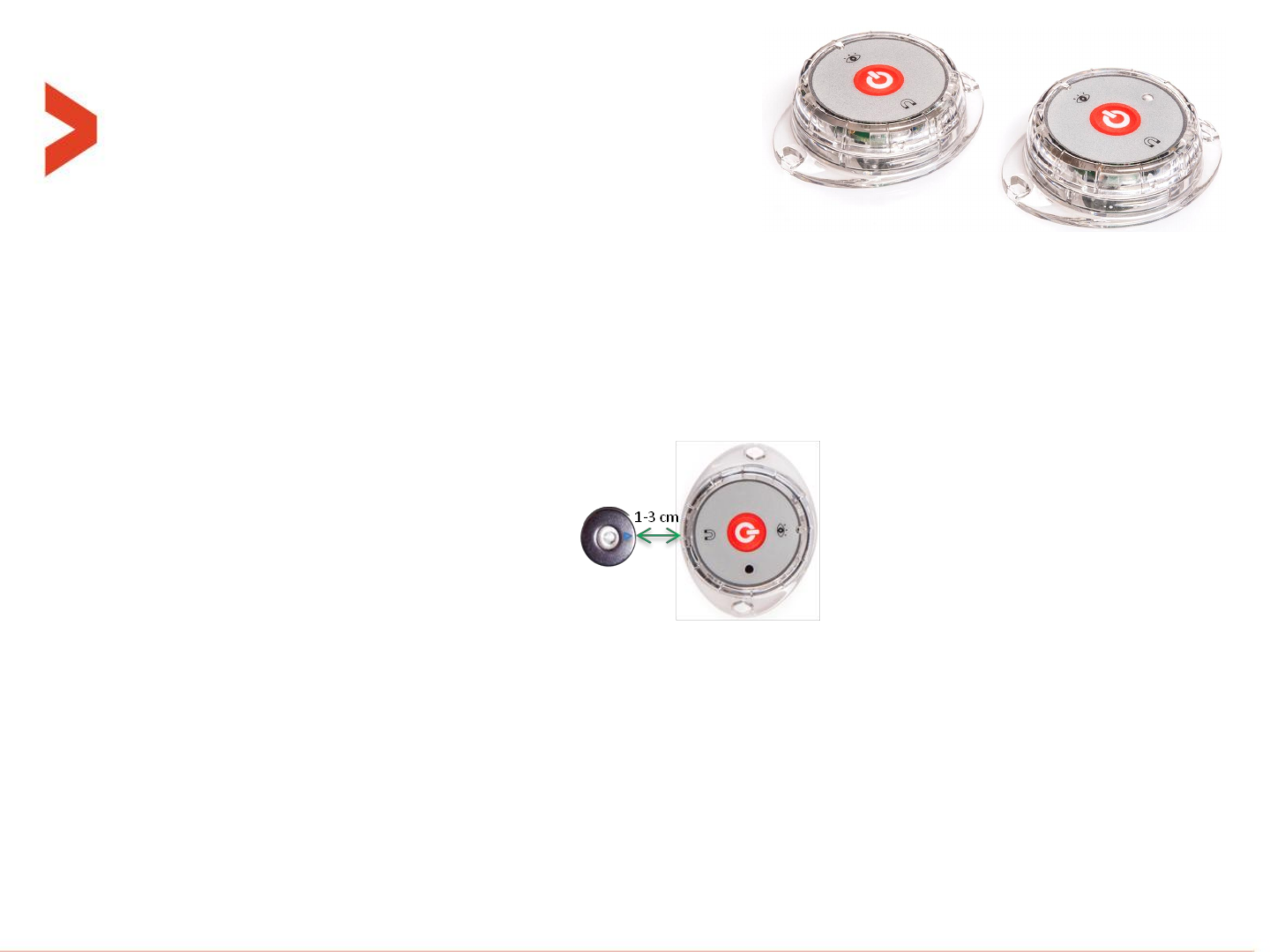
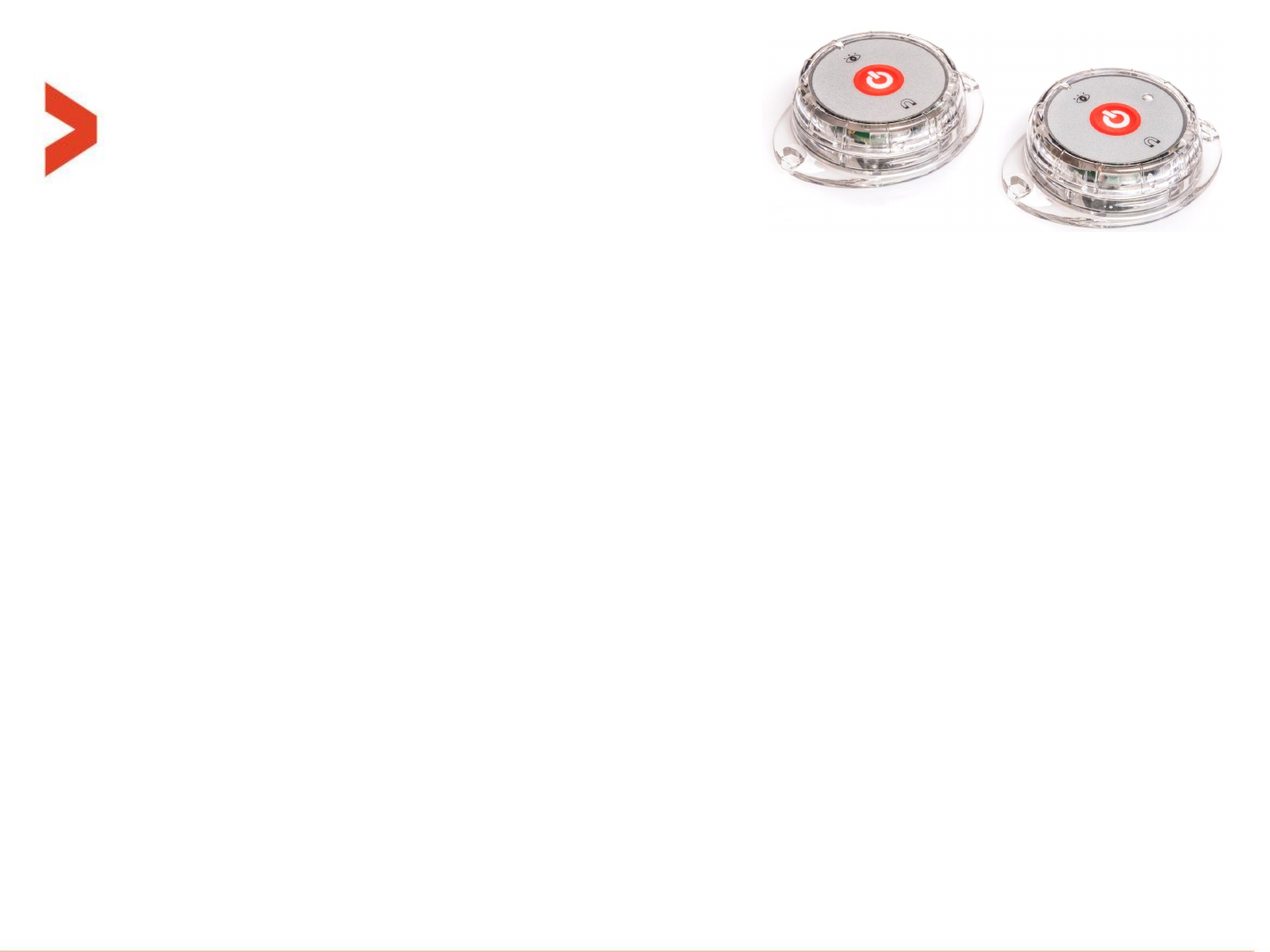
MultiSense
Marking:
–The magnet icon symbolizes the location of the magnet sensor. The permanent
magnet should be installed against it with distance of body-to-body of 1-3cm, while
the small triangle on the magnet points to the icon in the MultiSense.
–The eye icon symbolizes the light sensor direction, to which the source of light
should be directed.
Battery:
–Use only CR2450 size battery. Be careful not to install it at the wrong polarity as it
could damage the unit.
–Choose the exact battery model and manufacturer of the battery according to the
needed temperature range.
–To install a battery unscrew the upper half from the base half until the two triangles
on the side are aligned and then pull it.

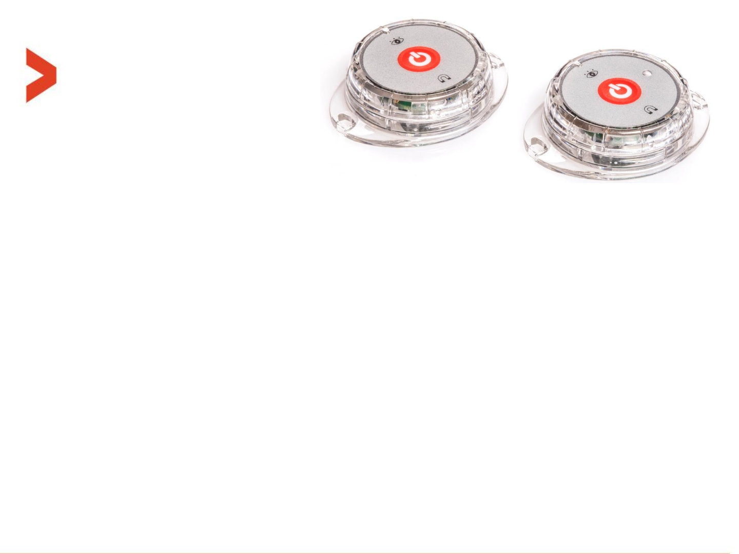
MultiSense
Button and blue LED:
–When battery is inserted, the unit always goes to active mode and the blue LED
lights for 3 seconds.
–When active, every short press (up to 1 second long) triggers sampling +
transmission and the blue LED blinks 5 times.
–When active, a long press (>4 seconds) will turn the unit OFF (inactive mode),
accompanied by 3 blue LED blinks.
–When the unit is off (inactive mode), a long press (>4 seconds) will turn the unit ON
and the blue LED lights for 3 seconds (same as battery insertion above).

Step by step guides

Step by step installation for evaluation
–The tools we provide for evaluation called “Evaluation Suite” and can be loaded
from our internet site at this address (requires login with username+password).
–This set of tools include the following nano related tools:
–The “Cellocator programmer” which is used to configure a single nano unit
and its related MultiSense units. It also includes the nano editor screen.
–The “Communication Center” which is used to get and interpreted / parse
the messages sent by a nano unit via the cellular link and also to send
some commands to the nano over the cellular link.
–The “Serial CSF STK Flasher” which is used to perform local FW upgrades of
the nano.
–The “Communication Logger” which can be used to sniff on various serial
communication links inside the nano board.
Step by step installation for evaluation
–Install the latest version of Cellocator’s evaluation suite. Install it as an
administrator.
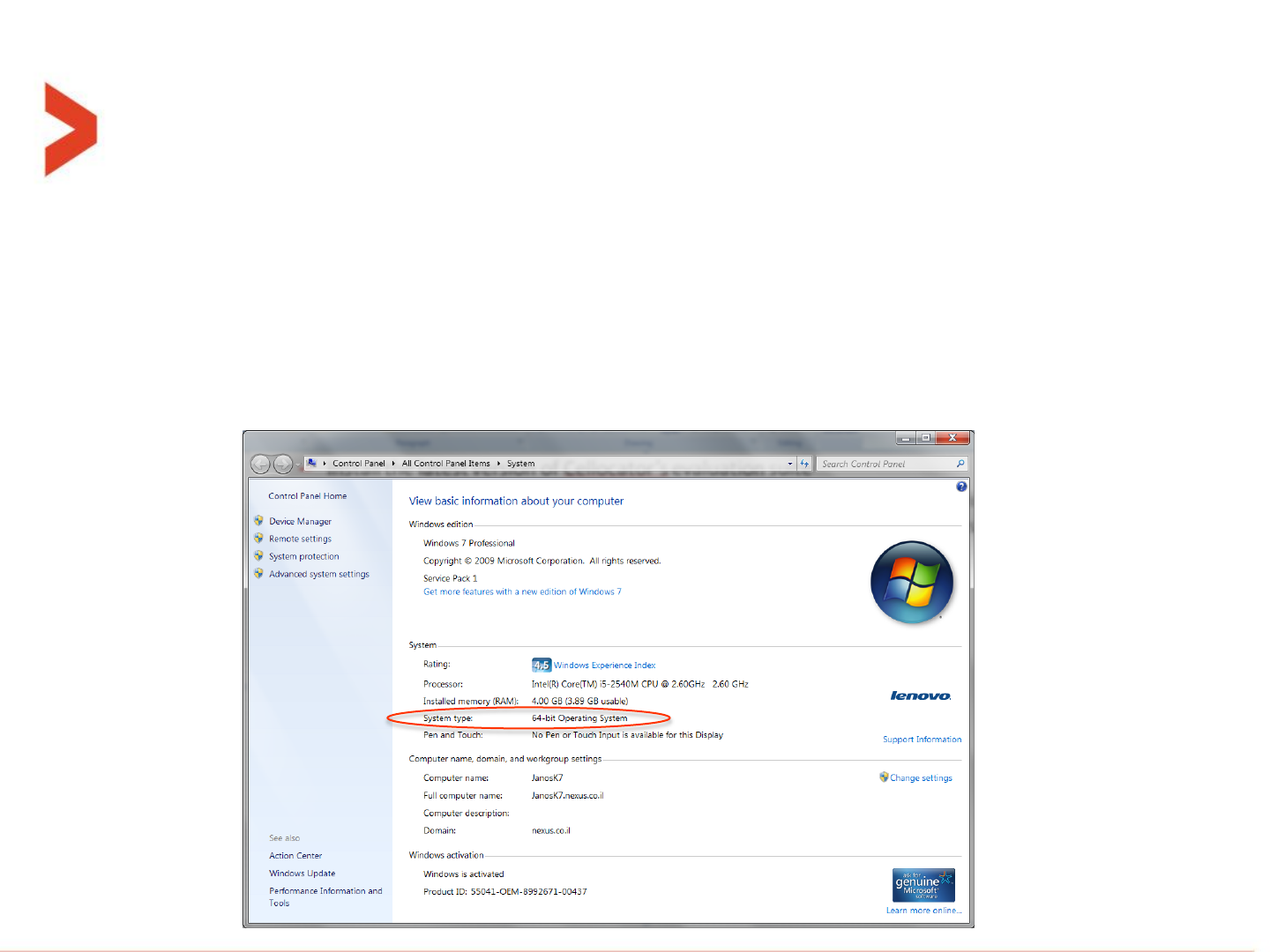
–Be sure to select the 64-bit or 32-bit installer version according to your windows
version. (Start button, or Windows+e then right click on computer -> properties
will reveal your version number). See example:
Step by step installation for evaluation
–Select the ‘Complete’ installation type, and then next->next…
–Follow security instructions related to installation of the evaluation suite.
–The installation process will automatically install the “ST virtual COM port”
windows driver if needed.
–After connecting the nano via the supplied micro-USB cable to the PC it will be
recognized and windows will allocate it a new COM port.
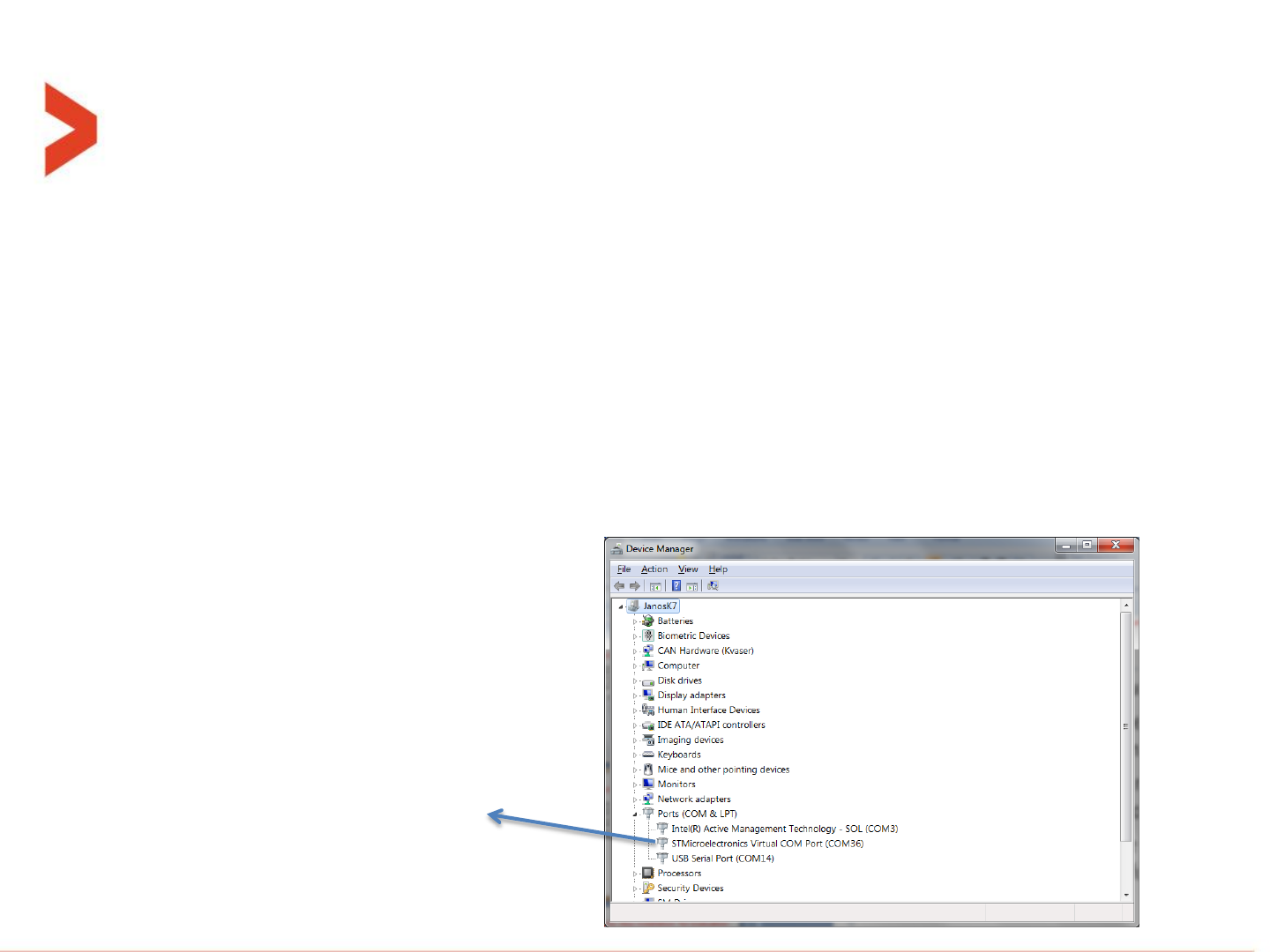
–Windows will declare which COM port number has been allocated. Anyway, this
port number can be found when opening the windows “Device manager” under
“Ports (COM & LPT)” folder:
In this example the
nano is at COM36
Step by step installation for evaluation
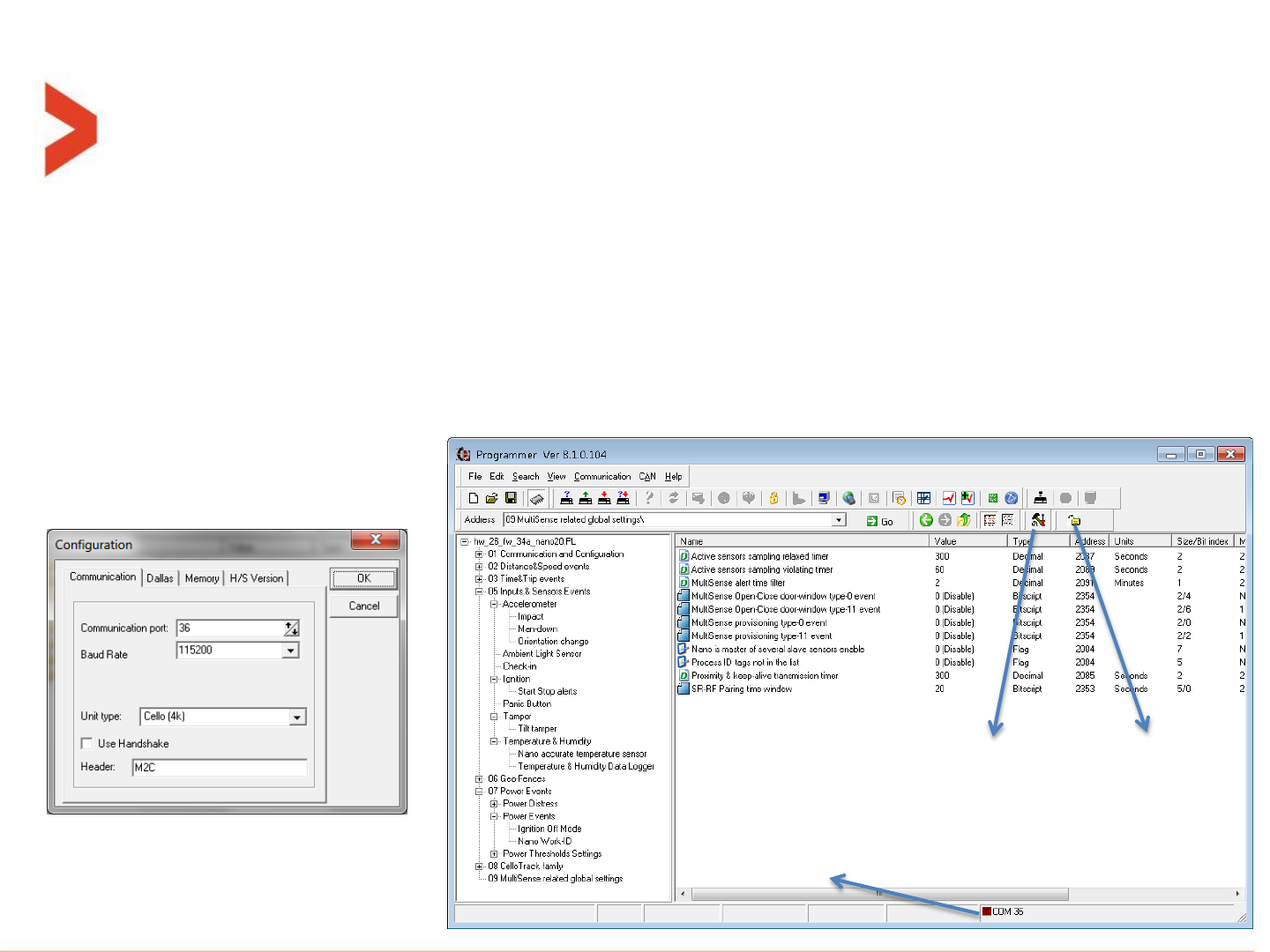
–Open Cellocator programmer utility. File open-> choose the latest nano PL file.
–For initial communication to begin, the nano COM port number should be set.
–Click on the “Configuration icon” (see below), select the “Communication” tab, and
set the COM port number. Then choose Baud rate of 115200, and Unit type “Cello
4K”. Close by pressing the OK button.
–The “Connection icon” (lock icon) should show closed-lock now and the connection
indication dot at the bottom of the window should turn from red to green.
Configuration
icon
Connection
icon
Connection
indication
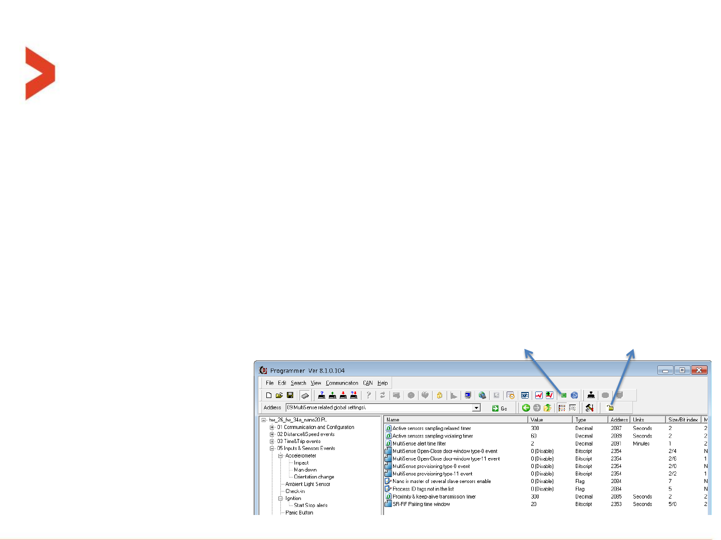
Step by step installation for evaluation
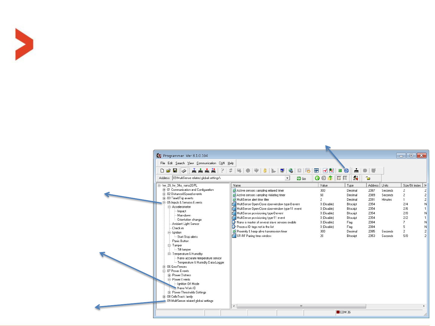
–The nano related parameters (on top of CelloTrack legacy parameters) resides in 2
areas. See the below screenshot.
–MultiSense units global settings is in separate folder (09). See below.
–All MultiSense units individual settings are under the “nano editor” screen. Press the
“nano editor” icon to open it and then select the “Sensors configuration” tab.
Inputs & Sensors folder
including the nano
specialized sensors and
related functionality
MultiSense related
global settings in new
folder
nano editor icon
Nano Work-ID feature
under Power Events
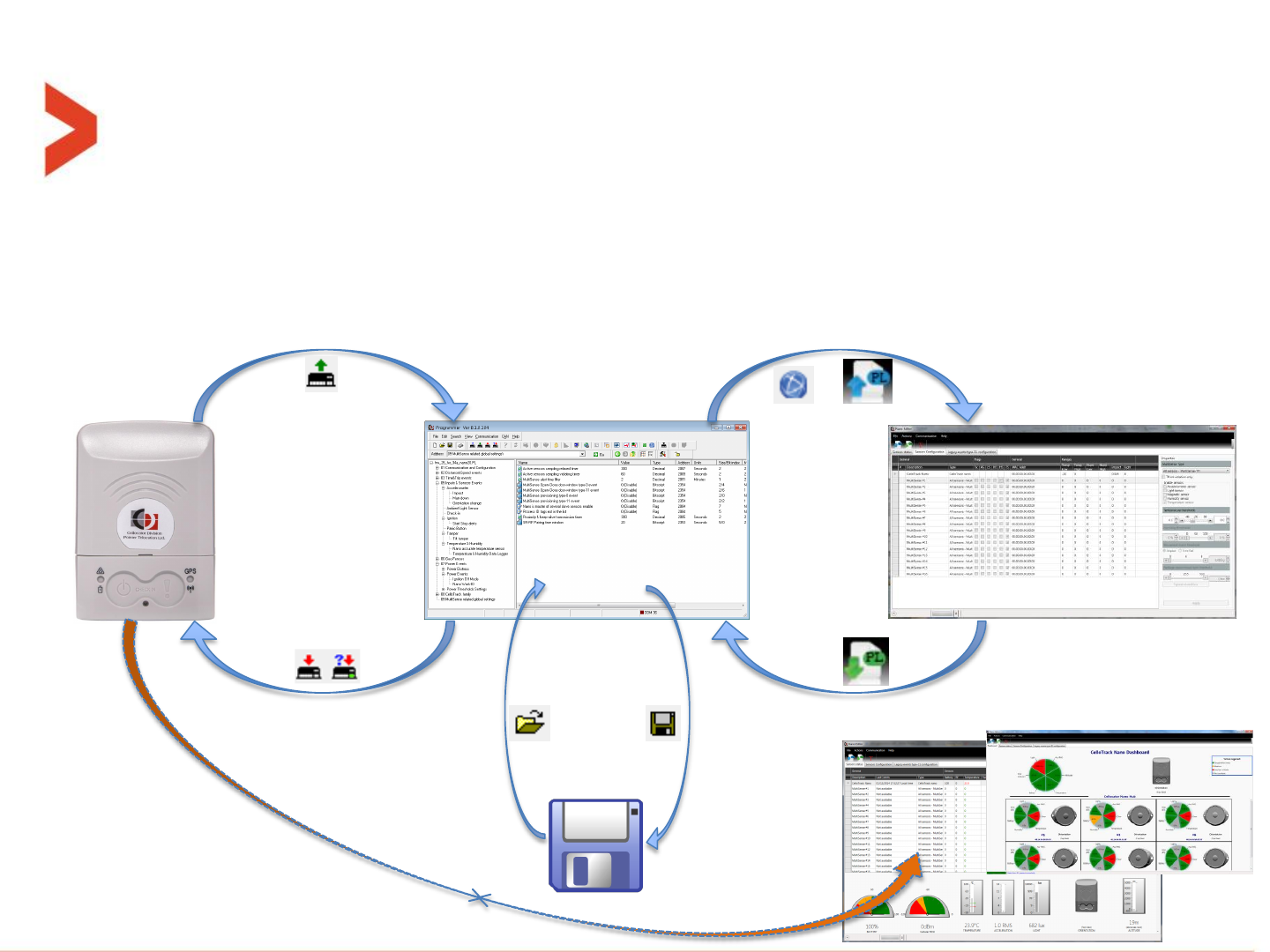
Step by step installation for evaluation
–The concept of operation and parameters flow between the 4 entities of HW,
programmer screen, storage and “nano editor” screen is as follows:
File
save
File
open
or
Open “nano editor” or Read from PL
Write to PL
Upload parameters
Download parameters
Dashboard
direct link
Dashboard / Sensors status tabs
Sensors configuration tab
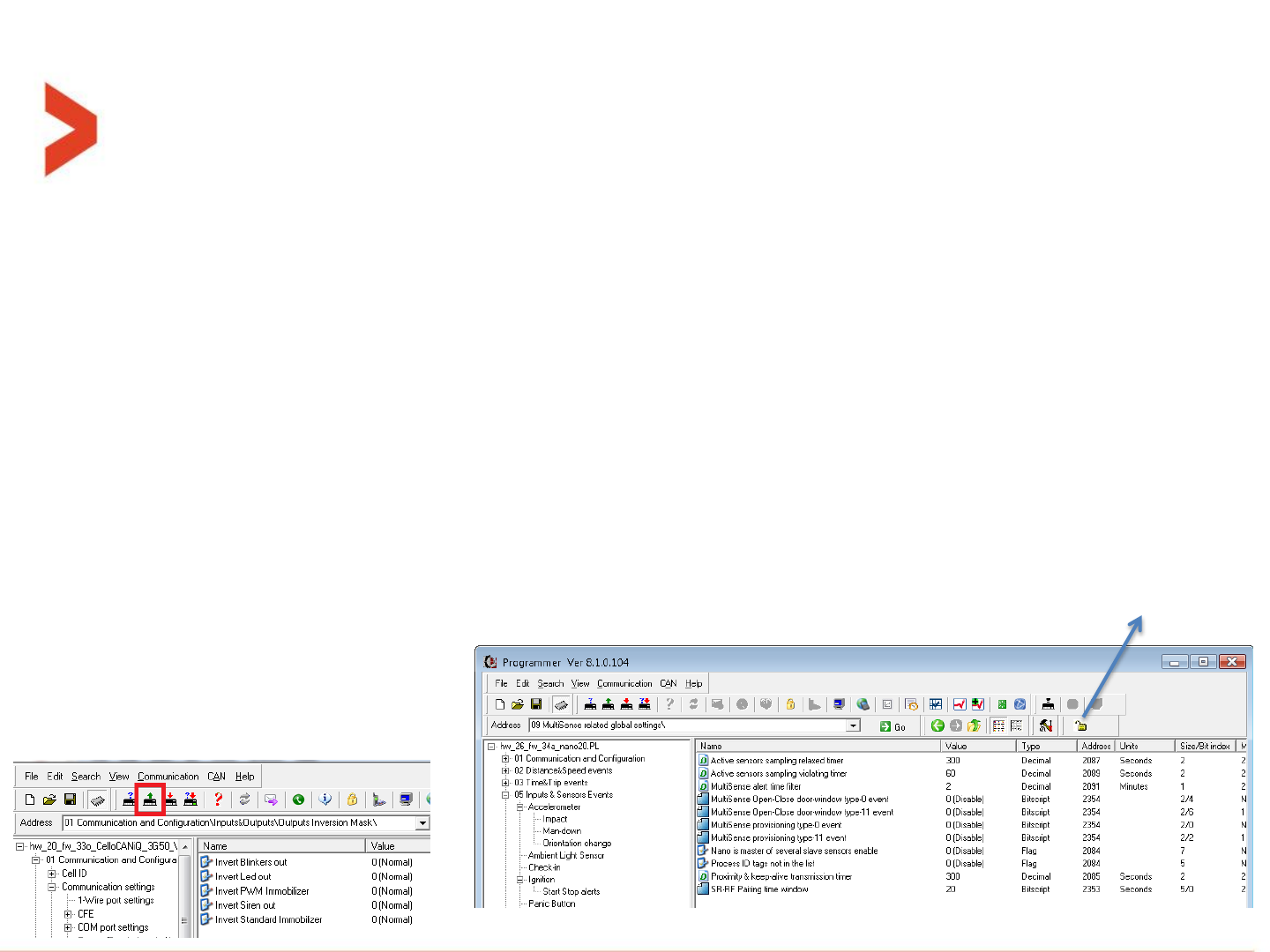
Step by step installation for evaluation
–If you want to pair a MultiSense to the nano, first verify that parameter “Nano
is master of several slave sensors enable” is enabled.
–Go over the rest of the MultiSense parameters to fit your needs.
–If any of the above parameters are changed, it requires to reset the nano unit
for the changes to take effect. If needed, press the green reset button.
–If reset takes place, the connection with nano is lost and should be restored
manually after the reset sequence has completed (a beep is sound from the
nano). Reconnection is performed by pressing the connection (lock) icon.
Reset button Connection icon
Step by step installation for evaluation
–To enter the nano to Pairing window, it is recommended to open the lock by pressing the
“Connection icon” to disconnect the communication.
–Then disconnect the nano from the micro-USB cable.
–Press both nano buttons until sequence of 4 beeps and then a double-beep is sound from
its buzzer.
–The left LED will start blinking orange. This means the paring window is open for the
duration configured in “SR-RF Pairing time window” parameter.
–If any unknown to the nano MultiSense will be powered on (pushing the button for 5
seconds while unit is in OFF state, or battery insertion) in the vicinity, during this window,
it will be paired.
–If successfully paired, a long beep (2 seconds) will be sound from nano buzzer. Connection
icon
After successful pairing, to view the newly
paired MultiSense in the tool, you need to
read the list from the Nano back to the PC by
pressing the “Upload parameters” button.
See below:
Step by step installation for evaluation
–Inside that pairing window, if any paired MultiSense (with this nano) is turned
OFF, by pressing its button (when in ON mode) for >5 seconds, it will be
“Unpaired”.
–The pairing window is prolonged after each successful pairing or un-pairing
operation.
–When the window closed, the unit will either blink its right LED red shortly if
nothing has been paired or unpaired, or reset itself if some MultiSense units
have been paired or unpaired.
–After the reset, reconnect the USB cable and push the connection icon (the
lock).
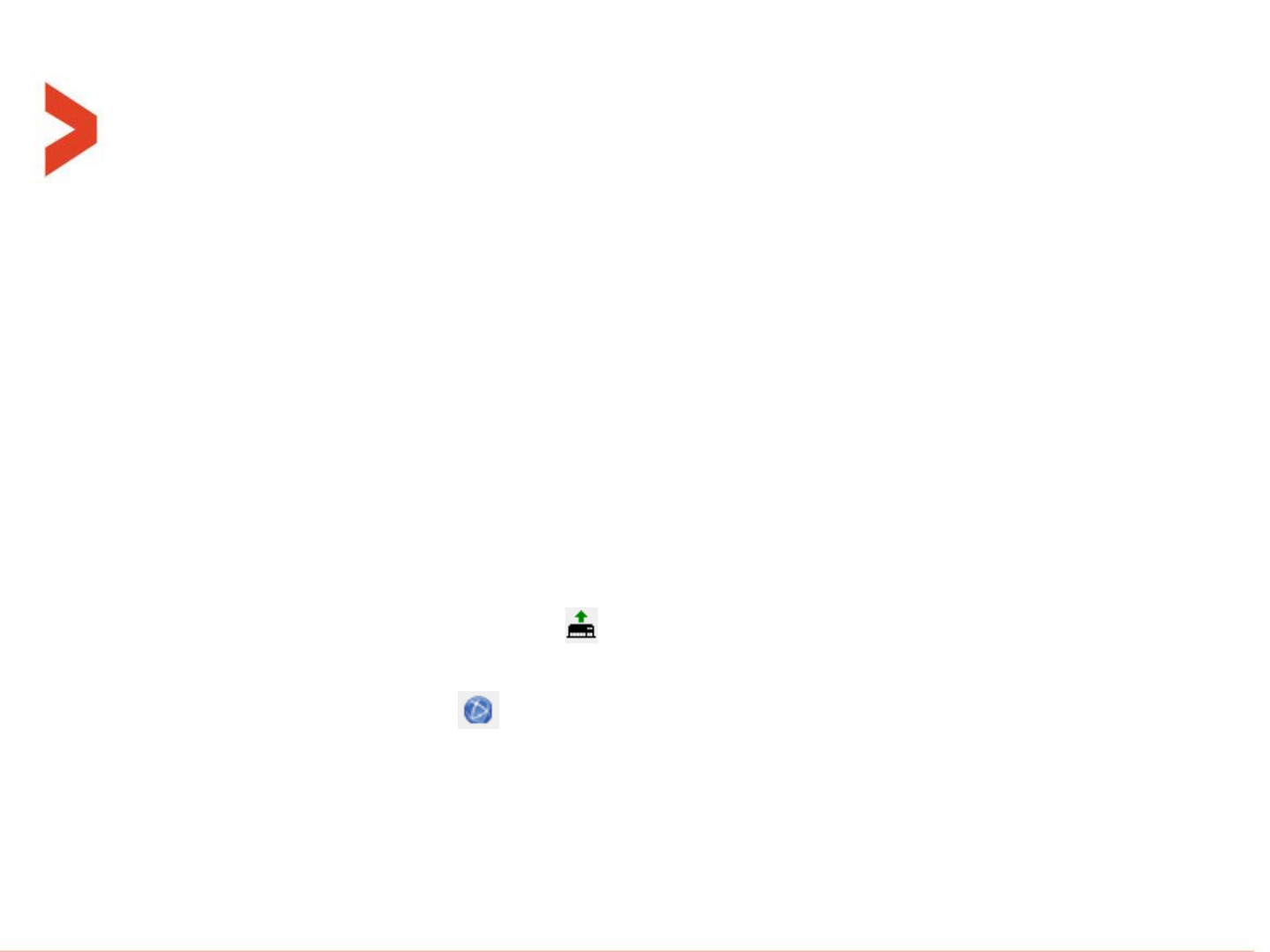
–Perform “Upload parameters” ( ) to update the programmer on the newly
paired MultiSense units.
–Open the nano editor ( ) and you can see in both “Sensors status” and
“Sensors configuration” tabs the new MultiSense status and configuration
respectively.
–Select the desired line to focus on by clicking on it.
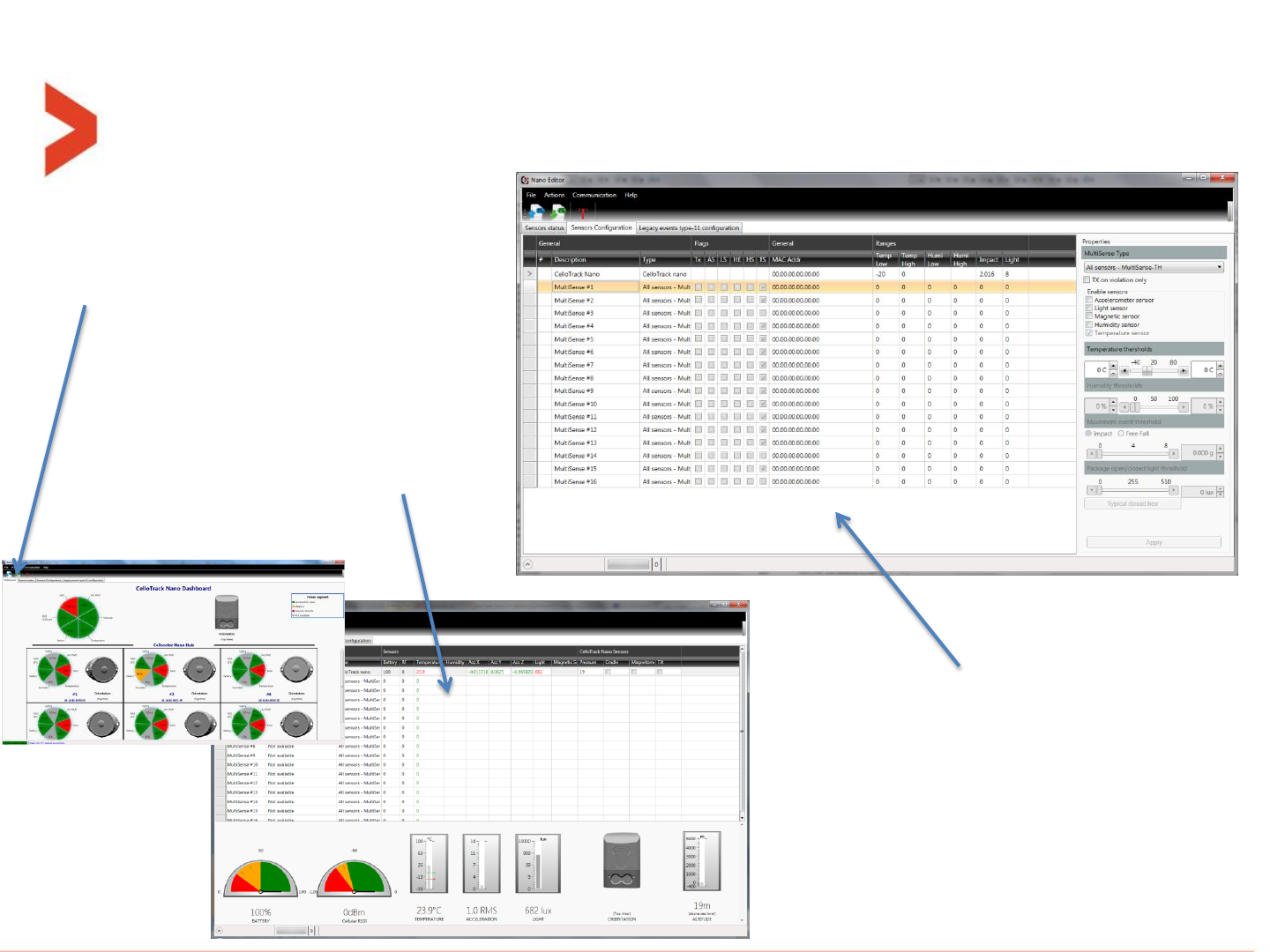
Step by step installation for evaluation
The first tab is a dashboard showing
an overview status, in real-time, of
the system components.
The third tab is a configuration
screen where some of the Nano
parameters and the individual
settings of each MultiSense unit can
be changed. (also support multiple
edits in single operation)
The second tab shows the
current status, in real-
time, of selected device,
nano or one of the
MultiSense units.
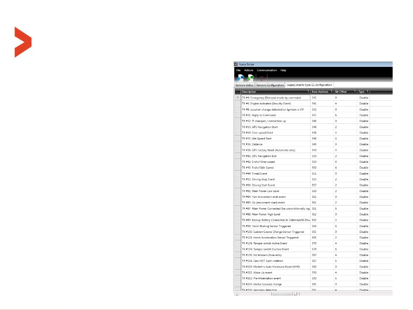
Step by step installation for evaluation
The 4th tab is a configuration screen for
setting each legacy (type-0) event, whether
to be sent also in an “Encapsulated” way
over type-11 message or not.
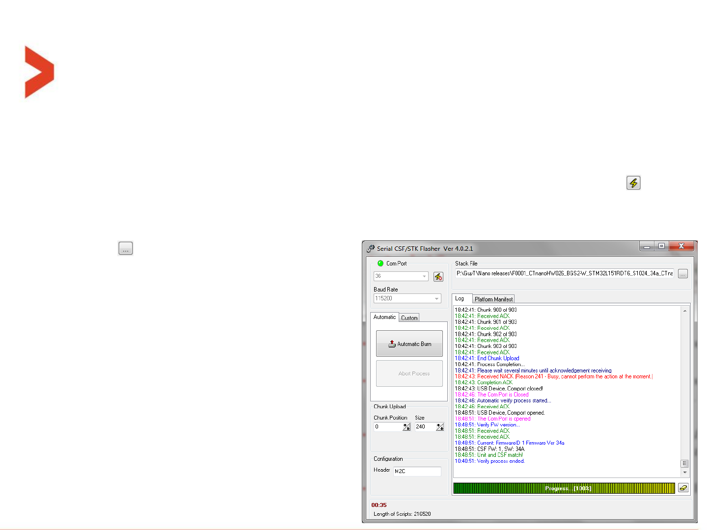
Step by step nano FW upgrade
–To update the FW version of the CelloTrack nano device, you will need the tool called
“Serial CSF STK Flasher” (separate installation from the evaluation tools).
–Close all application that might open the nano COM port, like Cellocator programmer etc.
–Open the tool, direct it to the nano’s COM port number and press the lightning icon: .
–If communication is OK, the “Com Port” light will change from red to green.
–Select the desired CSF file by pressing on
The button.
–Push the “Automatic Burn” button.
–Follow the on screen instructions to the
completion of the process.
–The whole process takes around
7 minutes.
–At completion, the COM port is
reconnected by the tool.
–Just close the application or disconnect
and connect to another unit.

Overview about Type-11 integration

Messaging concept in CelloTrack-nano
–All functionality of the CelloTrack nano events uses Type-0 legacy events and/or
the advanced Type-11 messages, all according to the configuration bits per
feature.
–Each nano specialized feature will have these 4 bits of configuration:
–Type-0 could also be "Active log event" or not, depending at the global (one per
system) bit of "Enable Active Events" (at address 0000.0 of the PL).
Bit 3
Bit 2
Bit 1
Bit 0
Type - 11
Type - 0
Logged
"Active log
event"
Logged
Distress

Messaging concept in CelloTrack-nano
–This will enable the user to select between the following options:
Type-11 options:
0= Disable
1= "Active Log Event"
2= Logged
Type-0 options:
0= Disable (the global "Active log event" bit will be ignored)
1= Distress (the global "Active log event" bit will be ignored)
2= Logged
3= Logged & Distress (not a recommended setting if the "Active log event" bit is
set, it will cause sending 2 messages per the event).
–The log memory supports both types simultaneously, as a continuous and united
space.
Note: When "Active log event" is used, the unit turn on the GNSS and wait for a fix (up to 90 seconds
timeout), if fixed is achieved, both the GPS stamp and time stamps of the event are overridden.
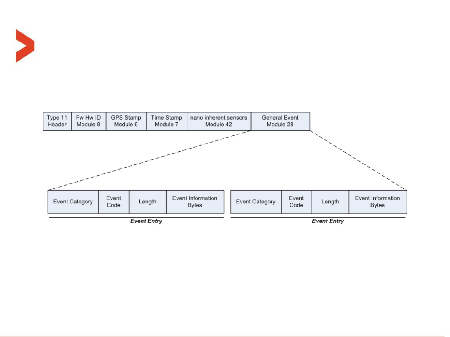
Type-11 message structures
–The “General Event Message is a Type 11 message designed to reflect system
events and notifications towards the server. The message is built as follows:
–Modules 8, 6, 7 and 42 are mandatory fields, and always come first in this exact
order, everything else (module 28 is just an example here) shall come after that.
–For more details go to the “Cellocator Wireless Communication Protocol”
document on section 5.

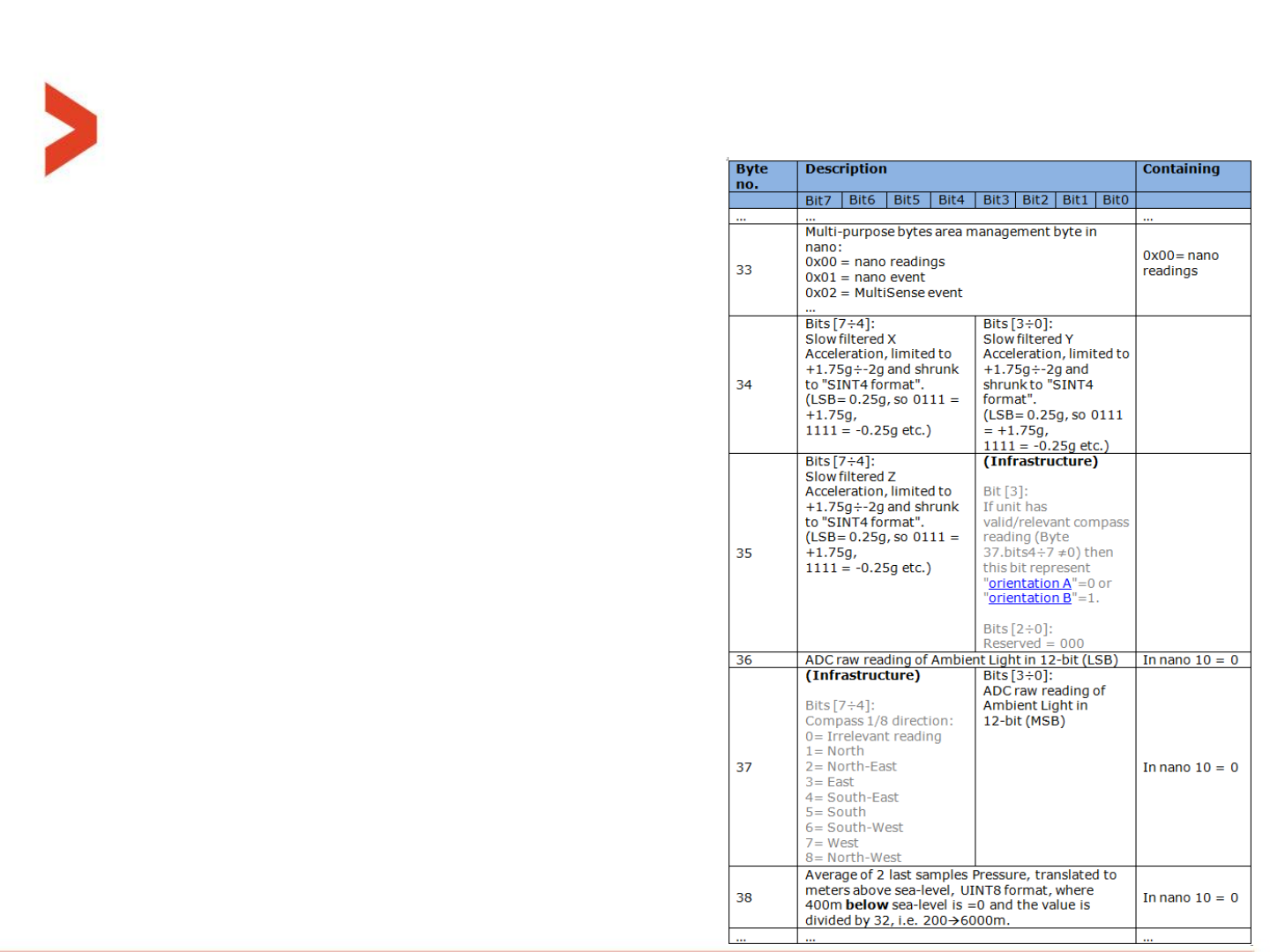
Parsing example
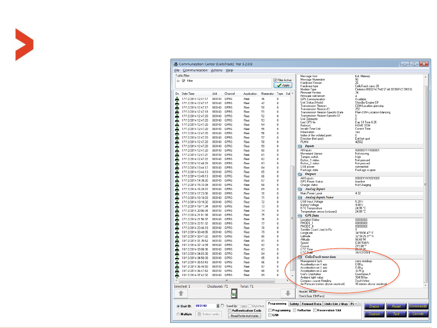
Example of an Type-0 message parsing
This is an example of type-0
message with the CelloTrack-
nano internal sensors data
fields, passed over the “Multi-
purpose bytes (33-38)” aka
Dallas bytes.
Example of an Type-0 message parsing
4D43475000C4790D0008815A1A220400
A600FC01C103480706DDF49718000000
0000D1E2620DA491000000093A44A303
8A175703E826000001000000640E1425
06120CDE07EB
Are parsed as follows:
00: nano readings
00: X= 0g , Y=0g
D1: Z= signed (0xD)= (-3) = -3*0.25g = -0.75g
E2 and 62: ADC= 0x2E2= 738 *0.25 = 184.5 lux
0D: Altitude = 13*32-400 = 16m

Example of an Type-11 message parsing
This is an example of type-11
message with the mandatory
modules and also module 28 for
conveying the actual event.

Example of an Type-11 message parsing
4D4347500BC4790D00088100004C0000000000080600000122011A000613
00000402095244A30384155703942F0000020000070700011E3A06120C0E
2A0F008EFF0C007BF0D0607C102C010160BD1C0A000101000B0004000000
00A6
Are parsed as follows:
Module 8 – HW and FW IDs.
Module 6 – GPS stamp.
Module 7 – GPS Time stamp
2A: Module 42
0F, 00: Length=15 bytes
8E, FF: (SINT16) X= -114 * 250µg= -0.0285g
0C, 00: (SINT16) Y= 12 * 250µg= 0.003g
7B, F0: (SINT16) Z= -3973 * 250µg= -0.99325g
D0, 60: ADC= 0x0D0= 208 *0.25 = 52 lux
7C, 10: Altitude = 0x107C4220/10-400= +22m
2C, 01: Temperature= 0x12C/10 = 30°C
01: Infrastructure
60: Battery level= 96%
BD: Cellular RSSI= -67dBm
1C: Module 28
0A, 00: Length=1
01: Number of entries=1
01, 00: Event category= nano
0B, 00: Event Code= Check-in
04: Length of data=4 bytes
00000000: Reserved (4 bytes)

Templates and expected battery life

About templates
In the PL file, there is a new feature that enables the user to quickly set a typical use
case configuration, that can be later fine tuned if needed.
This is done by using ready made templates. Currently we have 7 of them and they can
be selected by pressing the file Select Template from the main screen, or from the
template icon in the Nano editor screen.
For example: Template #1 is intended for long shipments, with paired MultiSense units,
with transmission every 15 minutes (“almost live tracking”).
Under nominal conditions, with 4 paired MultiSense units, the expected battery life of
the Nano is around 5.5 days.
Another example: Template #3 is a typical legacy use case of CelloTrack-T, using only
type-0 messages, but with addition of MultiSense units.
Under nominal conditions, with 4 paired MultiSense units, the expected battery life of
the Nano is around 40 days.
About templates
•Where temperature wasn’t mentioned, the battery performance is valid for +20°C
•The templates above and battery performances are based on calculated parameters (tens of parameters)
Template
number:
#1
#2
#3
#4
#5
#6
#7
Template name:
Long shipment
with MS
almost live-
tracking
Long shipment
without MS
almost live-
tracking
Typical
CelloTrack-T
users
improved
tracking
Long shipment
with MS, offline
tracking (15-25 C)
High value
goods
(3rd party
shipper)
Land shipment -
cold chain 2-8C
(food,
Pharmaceutical,
flowers,
antiques)
Employee
safety
(lone worker)
Scenario:
Nano: Tx every
15 min,
MS: Sample
every 1 min
Nano: Tx every
15 min
Nano: Tx every
24 hours,
MS: Sample
every 1 min
Nano: Live tracking
8h per day, logging
location every 5 min
MS: Tx every 5 min
Nano: Tx every
15 min
Nano: Tx every
15 min,
MS: Tx every 5
min
Nano: Tx every
6 hours
6 days
6 days
34 days
5 days
6 days
5 days
35 days
(optimal
condition)
12 days
(harsh conditions)
16 months
NA
16 months
22 months
NA
12 months
NA
FCC Compliance Statement
This device has been tested and found to comply with the limits for a Class B digital device, pursuant to Part 15 of the FCC Rules. These limits are
designed to provide reasonable protection against harmful interference in residential installations. This equipment generates uses and can radiate radio
frequency energy and, if not installed and used in accordance with the instructions, may cause harmful interference to radio and television reception.
However, there is no guarantee that interference will not occur in a particular installation. If this device does cause such interference, which can be verified
by turning the device off and on, the user is encouraged to eliminate the interference by one or more of the following measures:
– Re-orient or re-locate the receiving antenna.
– Increase the distance between the device and the receiver.
– Connect the device to an outlet on a circuit different from the one that supplies power to the receiver.
– Consult the dealer or an experienced radio/TV technician.
WARNING! Changes or modifications to this unit not expressly approved by the party responsible for compliance could void the user’s authority to operate
the equipment.
This device complies with Part 15 of the FCC Rules. Operation is subject to two conditions: (1) This device may not cause harmful interference, and (2)
this device must accept any interference that may be received or that may cause undesired operation.
This device complies with Industry Canada license-exempt RSS standards. Operation is subject to the following two conditions: (1) This device may not
cause harmful interference, and (2) this device must accept any interference received, including interference that may cause undesired operation.
(Le present appareil est conforme aux CNR d'Industrie Canada applicables aux appareils radio exempts de licence. L'exploitation est autorisee aux deux
conditions suivantes :(1) l'appareil ne doit pas produire de brouillage, et (2) l'utilisateur de l'appareil doit accepter tout brouillage radioelectrique subi,
meme si le brouillage est susceptible d'en compromettre le fonctionnement.).
To comply with FCC Section 1.1310 for human exposure to radio frequency electromagnetic fields and IC requirements, implement the following
instruction:
A distance of at least 20 cm. between the equipment and all persons should be maintained during the operation of the equipment.
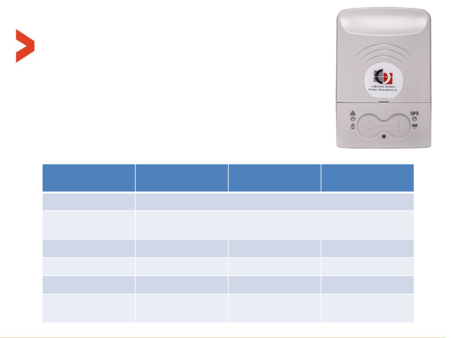
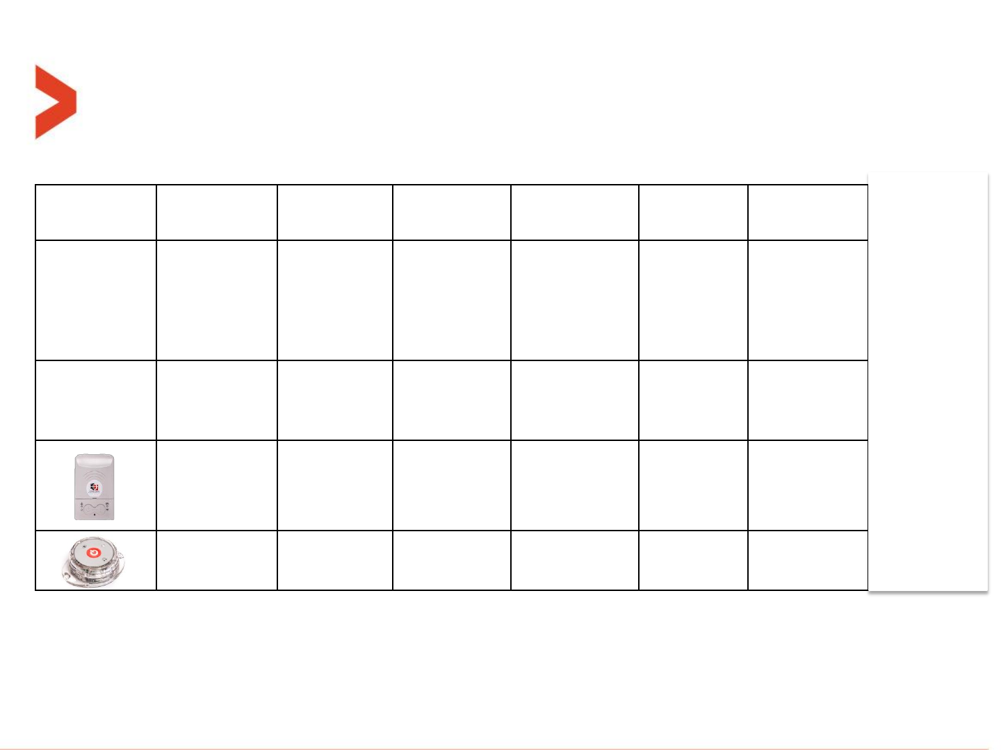
Table of products
Product name
P/N
HVIN
FVIN
CelloTrack Nano 20
GC9770001-000
A
34
CelloTrack Nano 20 3G
GC9771004-000
B
34
CelloTrack Nano 10
GC9770002-000
A
34
CelloTrack Nano 10 3G
GC9771003-000
B
34
MultiSense
715-50100
C
4
MultiSense-TH
715-50200
D
4

Thank You!