POINTER TELOCATION RMU17UHF-NXUS User Manual TABLE OF CONTENTS
POINTER TELOCATION Ltd. TABLE OF CONTENTS
Contents
- 1. User Manual
- 2. Revised Installation Manual
Revised Installation Manual
Customer Support
CL-01.005
October, 2001
____________________________________________________________________________________________________________________
RMU17 Installation- instruction.doc Page 1 of 9
NXRMU52000-3 ( = “RMU”) INSTALLATION
INSTRUCTIONS
Revision Record:
Date Description Written by Rev.
Oct-01 Initial release Amit Gelber -
The FCC Wants You to Know
This equipment has been tested and found to comply with the limits for a Class B digital device,
pursuant to Part 15 of the FCC rules. These limits are designed to provide reasonable protection
against harmful interference in a residential installation. This equipment generates, uses and can
radiate radio frequency energy and, if not installed and used in accordance with the instructions,
may cause harmful interference to radio communications. However, there is no guarantee that
interference will not occur in a particular installation. If this equipment does cause harmful
interference to radio or television reception, which can be determined by turning the equipment off
and on, the user is encouraged to try to correct the interference by one or more of the following
measures:
a) Reorient or relocate the receiving antenna.
b) Increase the separation between the equipment and receiver.
c) Connect the equipment to an outlet on a circuit different from that to which the receiver is
connected.
d) Consult the dealer or an experienced radio/TV technician.
FCC Warning !
Modifications not expressly approved by the manufacturer
could void the user authority to operate the equipment under FCC Rules.
This document contains proprietary information that is the sole property of NEXUS Telocation Systems Ltd.
The document is submitted to the recipient for his use only. By receiving this document; the recipient undertakes
n
ot to duplicate or to disclose, in part or the whole, any of the information contained herein; to any third party;
w
ithout a-priory written permission from NEXUS Telocation Systems Ltd.

Customer Support
CL-01.005
October, 2001
____________________________________________________________________________________________________________________
RMU17 Installation- instruction.doc Page 2 of 9
Important!
For proper, reliable functioning of the RMU, read the installation instructions carefully.
Before installing the RMU, pay attention to those basic rules:
• Before installing the RMU in the vehicle, check that the correct voltage is supplied.
• Do not install the RMU close to heat sources (heating system outlets).
• Install the RMU in watertight locations ONLY.
• Do not install the RMU in the engine compartment.
• Do not install the RMU behind the fuse box.
• Insulate all loose cables.
• Secure the RMU with screws or strips.
• Install the RMU in the passenger compartment or in the trunk.
• Conceal the RMU, including cables, when installing.
Instructions concerning human exposure to radio
frequency electromagnetic fields.
To comply with FCC, Section 1.1307(b) (1) for human exposure
to radio frequency of electromagnetic fields, implement the
following instructions:
1. The installation position of the antenna shall provide a separation distance of at least 20 cm.
between the general public, the user, and the equipment antenna.
2. The equipment user should keep a distance of at least 20 cm. from the equipment antenna.
Customer Support
CL-01.005
October, 2001
____________________________________________________________________________________________________________________
RMU17 Installation- instruction.doc Page 3 of 9
Wiring Connections:
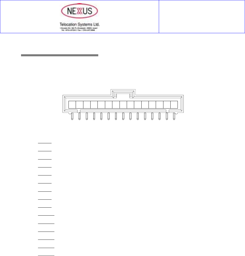
The RMU (Ver. 1.7), uses “Molex” type connector (Serial number 70553-0014), as following:
15 14 13 12 11 10 9 8 7 6 5 4 3 2 1
Pin 1 : Ground
Pin 2 : +12v
Pin 3 :+Rx Data
Pin 4 :- Rx Data
Pin 5 :+Tx Data
Pin 6 :- Tx Data
Pin 7 : Output “B”
Pin 8 : LED
Pin 9 : Output “A”
Pin 10 : Output “C”
Pin 11 : Input “A”
Pin 12 : Input “B”
Pin 13 : Input “C”
Pin 14 : Input “D”
Pin 15 : Output “Gnd.”
Customer Support
CL-01.005
October, 2001
____________________________________________________________________________________________________________________
RMU17 Installation- instruction.doc Page 4 of 9
Wiring Diagram:

Customer Support
CL-01.005
October, 2001
____________________________________________________________________________________________________________________
RMU17 Installation- instruction.doc Page 5 of 9
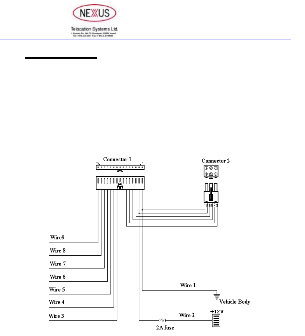
Connecting the Wires - Connector 1
ELECTRICAL INTERFACE
Pin Name Description
1 Ground.
2 Vcc (+ 12V).
Power Supply.
Vcc Range (8-17 Volt)
3 RS 422 (Rx+)
4 RS 422 (Rx-)
5 RS 422 (Tx+)
6 RS 422 (Tx-)
Serial Port.
7 OUTPUT BOFF = 0 Volt.
ON = 12 Volt / 130 mAmp
8 OUTPUT LED 12 mAmp max
9 OUTPUT AOFF = 0 Volt.
ON = 12 Volt / 130 mAmp
10 OUTPUT COFF = 0 Volt.
ON = 12 Volt / 130 mAmp.
11 INPUT ADefault: Active High. (>3.0 Volt)
12 INPUT BDefault: Active Low. (< 0.6 Volt)
13 INPUT CDefault: Active Low. (< 0.6 Volt)
14 INPUT DDefault: Active Low. (< 0.6 Volt)
15 OUTPUT GND. Internal Loop.
Wire 1: Connect Wire 1 permanently to the vehicle body. The connection site must be
protected against corrosion.
Wire 2: Connect Wire 2 to a permanent positive connection (+) in the fuse box.
Wire 3: See Option 2.
Wire 4: See Option 1.
Wire 5: See Option 1.
Wire 6: Optional connection to alarm system.
Outlet A. Connect through relay to the output of an additional alarm system
siren.
Customer Support
CL-01.005
October, 2001
____________________________________________________________________________________________________________________
RMU17 Installation- instruction.doc Page 6 of 9
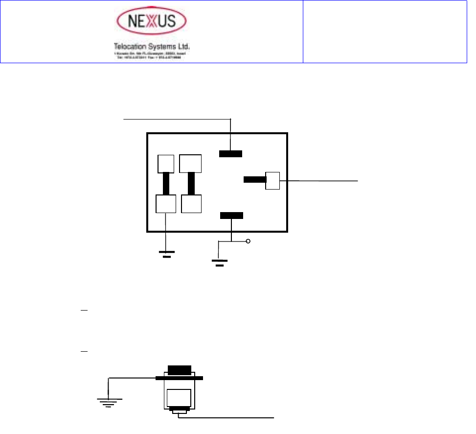
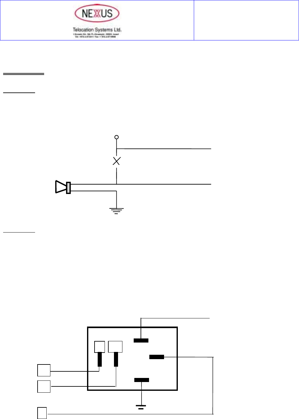
Connect according to the diagram:
Note: The connection numbers correspond to the BOSCH 12V 40A relay.
Wire 7: Outlet B. Do not connects. Insulate outlet B.
Wire 8: Optional connection for distress button.
Outlet C. Can be use as an distress button outlet.
Wire 9: Do not connect. Insulate Wire 9.
85
30
C
86
87A
87
NO NC
External Siren
Output
+12v
Wire 6
Distress Button
O.N
Wire 8
Customer Support
CL-01.005
October, 2001
____________________________________________________________________________________________________________________
RMU17 Installation- instruction.doc Page 7 of 9
Installing Antennas
Important!
Proper installation of the antennas is vital for the reliable functioning of the RMU.
Very important:
• Do not shorten or lengthen the antenna cables.
• Do not position the antennas near the vehicle computer or any other transmitter.
• Do not combine antennas.
• Position antennas at least 10 cm away from metal.
• Antennas can be installed horizontally or vertically. The cable can be rolled up.
• Antennas can be fixed or held in position using adhesive tape or strips.
Optional Antenna Sites :
Front dash board: Inside the upper section of the dash board. The antennas
are positioned above the window line.
Rear dash board: Between the shelf and the metal surface. Position as far
away as possible from the metal. Mount above the
window line.
On the vehicle ceiling: The RMU can be installed in trucks or cars that have a
space (at least 10 cm) between the ceiling covering and
the ceiling. Antennas can be distributed.
Customer Support
CL-01.005
October, 2001
____________________________________________________________________________________________________________________
RMU17 Installation- instruction.doc Page 8 of 9
Options
Option 1:
Wires 4 and 5: Split alarms. No connection to an additional siren. Wires 4 can serve and 5 as current
detector (up to maximum 1.5 Amp.).
Option 2:
Wire 3: Positive (+) output (up to 130mA) to an external relay.
The output (Wire 3) can be used to operate an external relay. The relay serves to
connect/disconnect an accessory in the vehicle, e.g. indicators, additional siren,
etc.
The relay is controlled by the control center.
Siren
+12v
Wire 4
Wire 5
85
30
86
87A
87
C
NO
NC
Wire 3
Customer Support
CL-01.005
October, 2001
____________________________________________________________________________________________________________________
RMU17 Installation- instruction.doc Page 9 of 9
The RMU kit includes:
Electrical diagram - BOSCH 12V 40A relay
Attention !
wiring and unit is not to be exposed to oil
and/or grease such as in engine compartment.
C-30
86
85
NC-87A
NO-87