PORTECH SYSTEMS MH5100 10.1 inch Integrated Pad User Manual
PORTECH SYSTEMS Co.,Ltd 10.1 inch Integrated Pad Users Manual
UserManual.wiki
>
PORTECH SYSTEMS
>
MH5100 User Manual
>
Users Manual
Contents
1.
Users Manual
2.
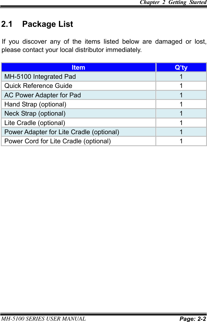
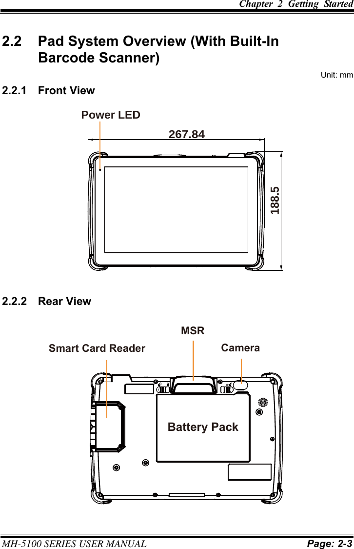
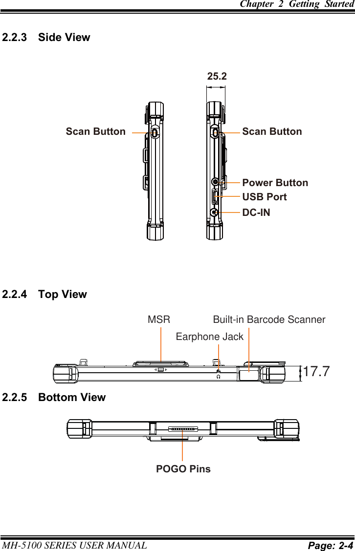
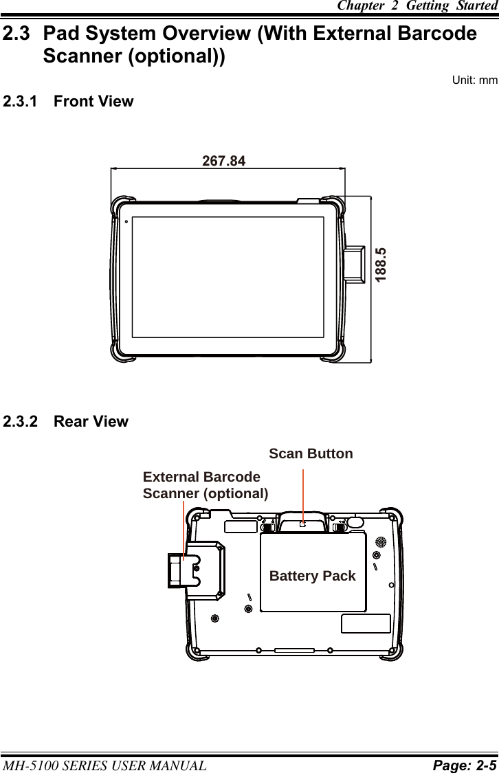
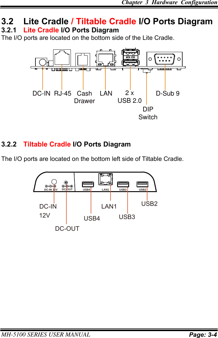
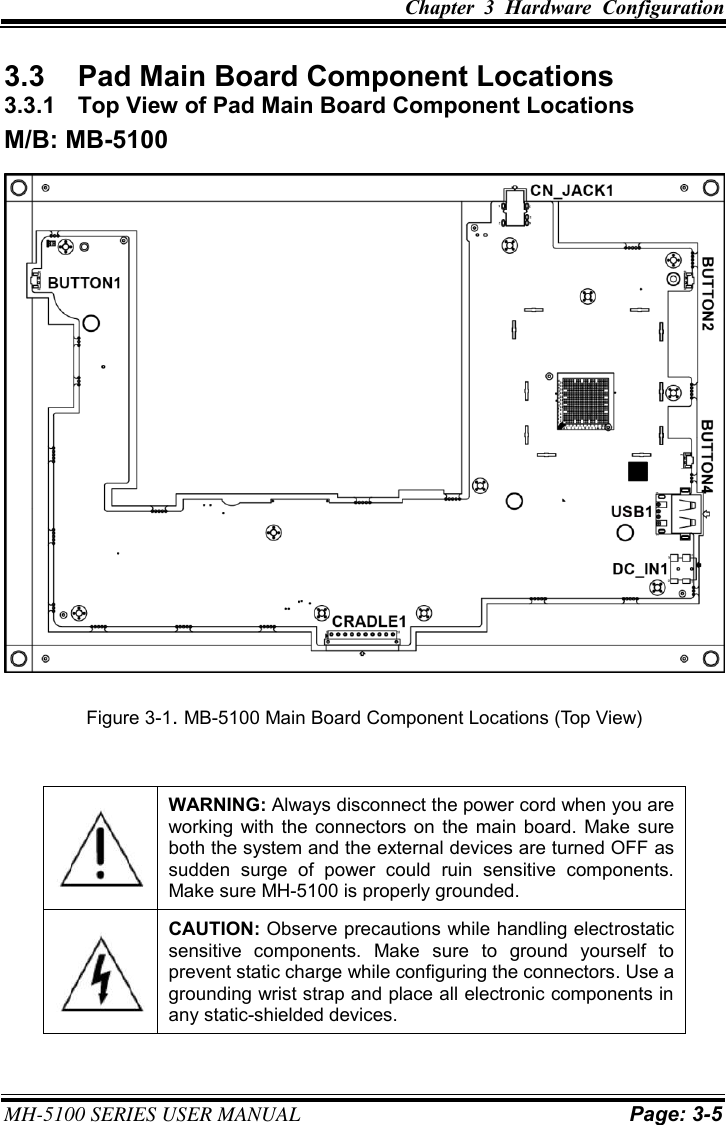
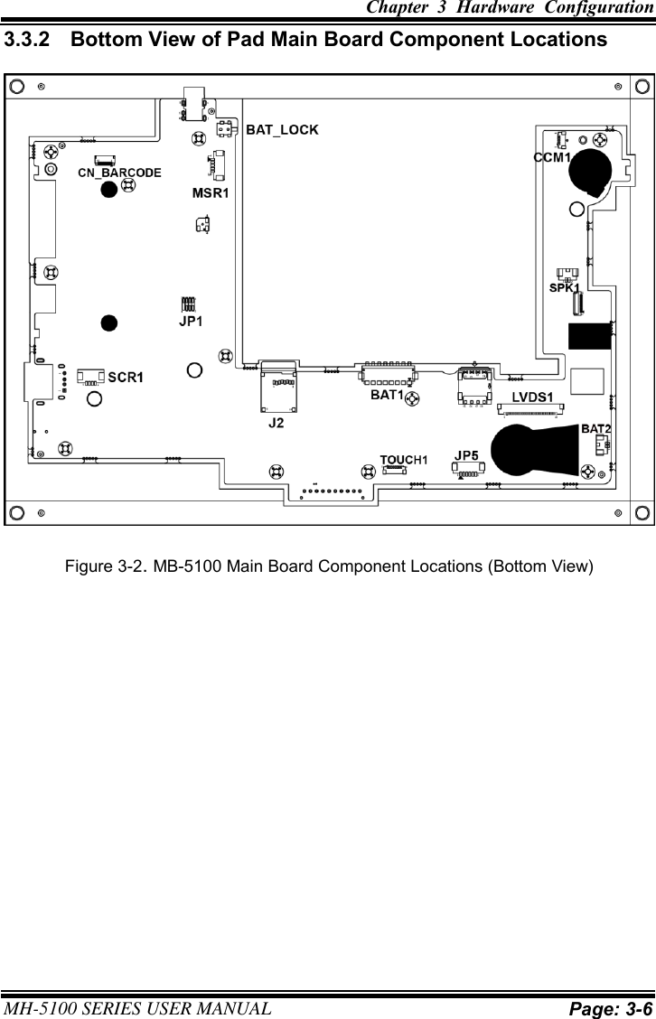
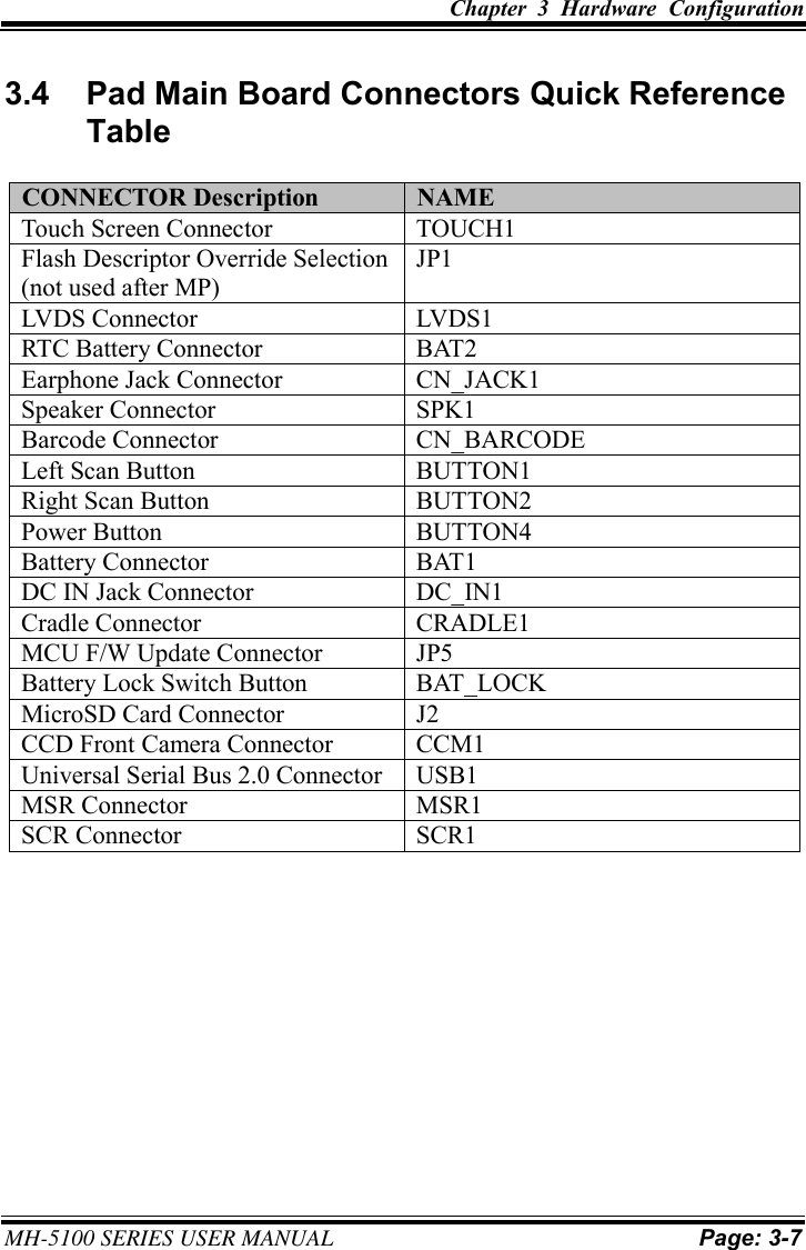
User Manual
Users Manual
Navigation menu
Upload a User Manual
Namespaces
Wiki Guide
HTML
PDF
Info
Views
User Manual
Discussion / Help
Navigation
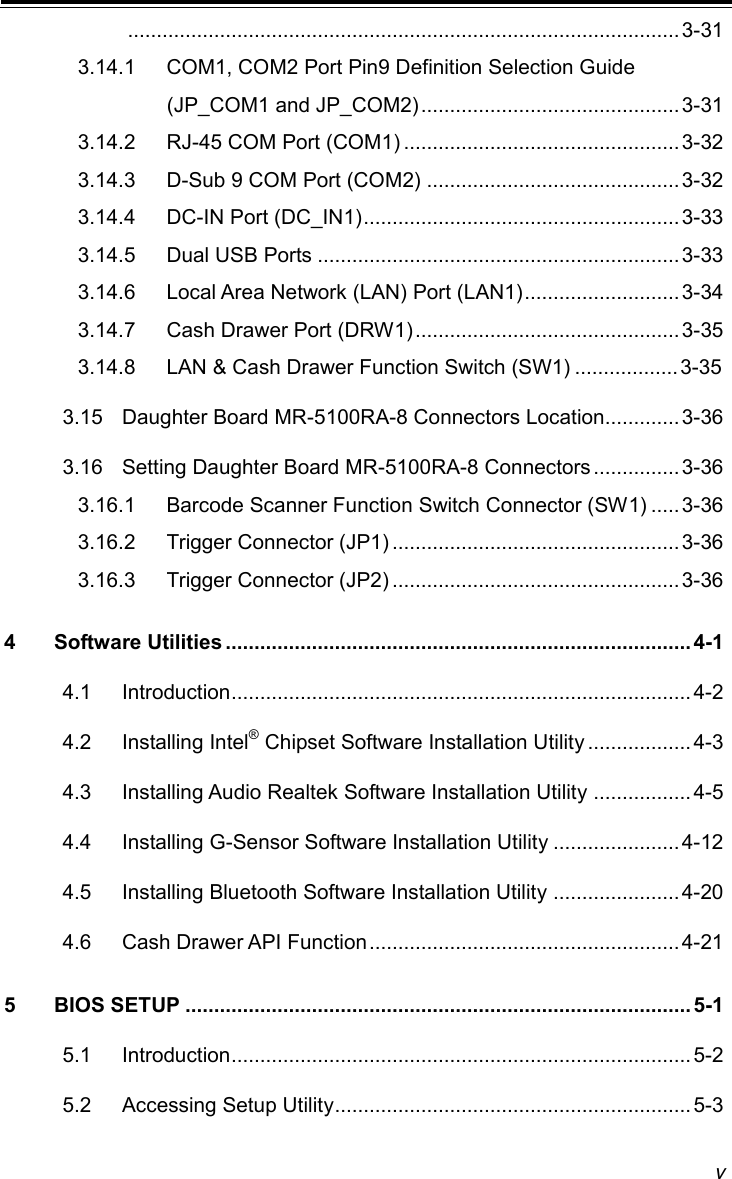


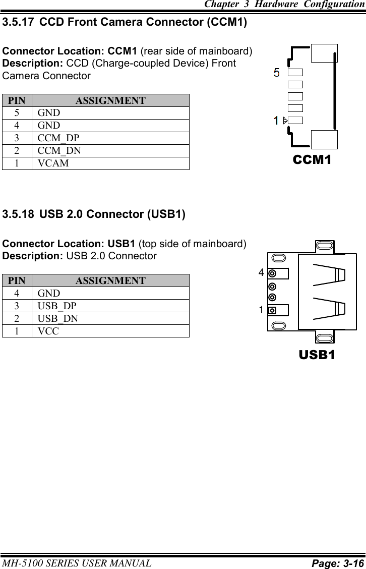
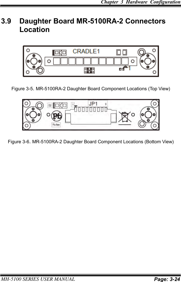
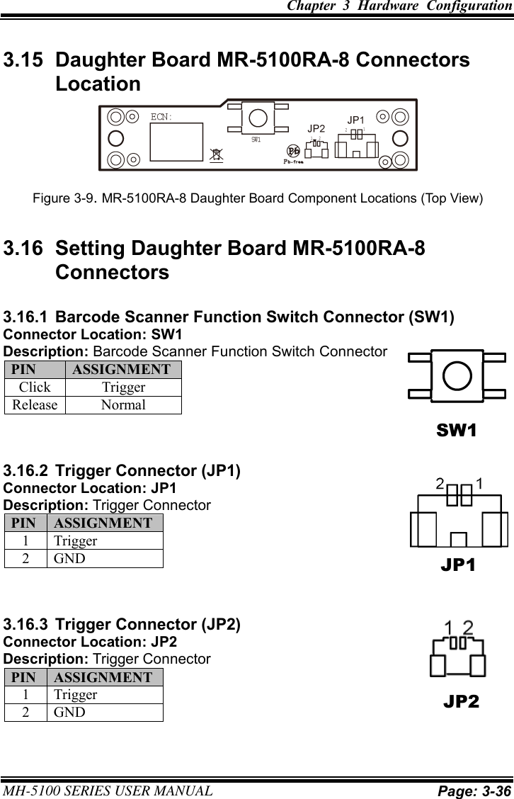
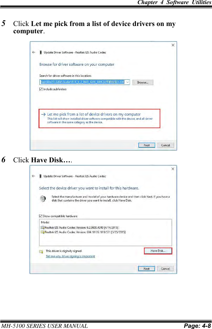
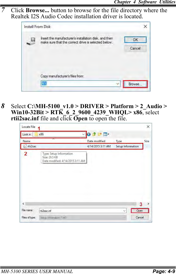
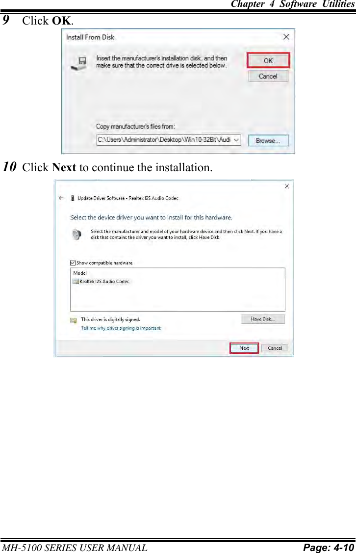
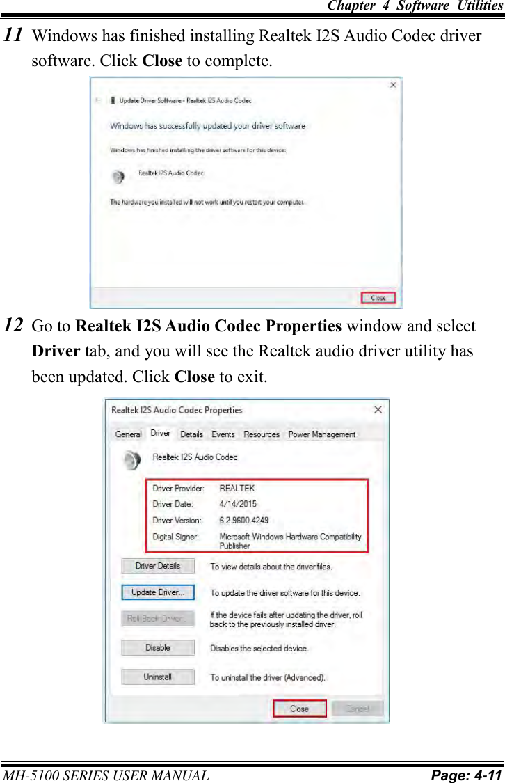
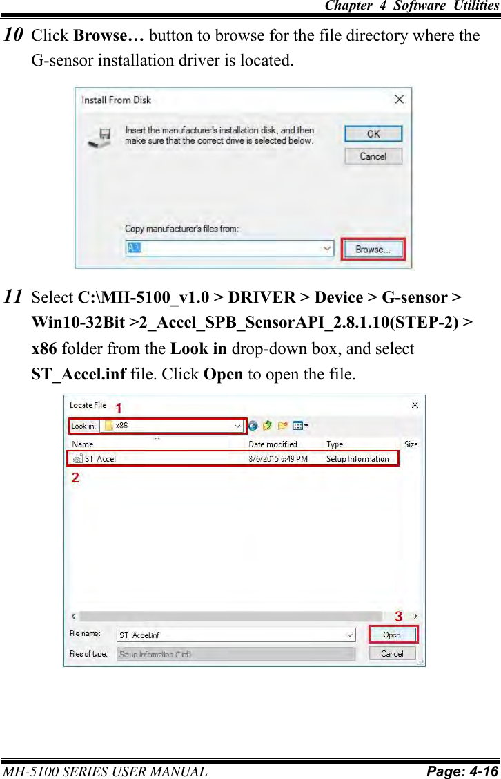
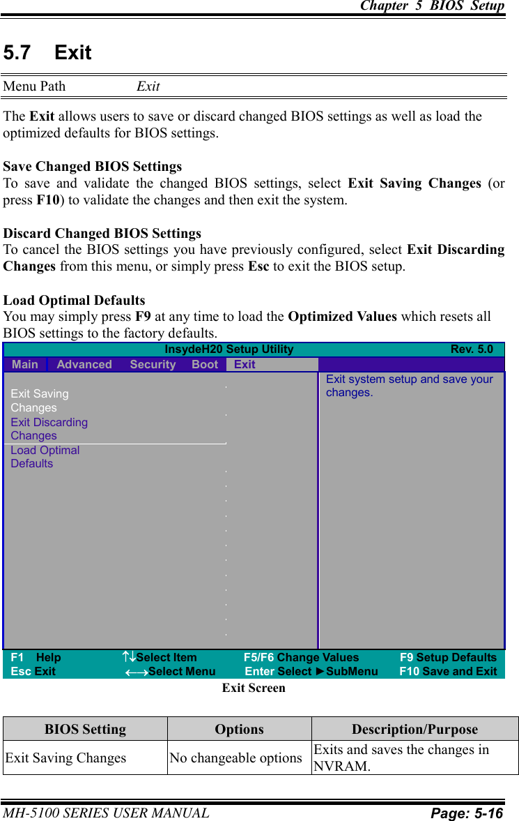
![Chapter 5 BIOS Setup MH-5100 SERIES USER MANUAL Page: 5-5 Press <Esc> (the one that shares the decimal point at the bottom of the number keypad) to select SCU icon to access the Setup program. In a moment, the main menu of the Insyde Setup Utility will appear on the screen: InsydeH20 Setup Utility Rev. 5.0 Main Advanced Security Boot Exit BIOS Version 51000PTA Select the current default language used by the InsydeH20. Build Date 05/11/2017 Build Time 14:10:19 MCU Version: 170210 Processor Type System Bus Speed System Memory Speed Cache RAM Total Memory Intel® Atom™ CPU Z3736F @ 1.33 GHz 83 MHz 1333 MHz 1024 KB 2048 MBeMMC Total Size: 32 GB VGFX value: 1.00 VCore value: 0.71 VDDR value: 1.350 Language <English> System Time [10:50:39] System Date [12/14/2016] F1 Help Select Item F5/F6 Change Values F9 Setup Defaults Esc Exit Select Menu Enter Select ►SubMenu F10 Save and Exit BIOS Setup Menu Initialization Screen You may move the cursor by <↑> and <↓> keys to highlight the individual menu items. As you highlight each item, a brief description of the highlighted selection will appear at the bottom of the screen. The language of the BIOS setup menu interface and help messages are shown in US English. You may use <↑> or <↓> key to select among the items and press <Enter> to confirm and enter the sub-menu. The following table provides the list of the navigation keys that you can use while operating the BIOS setup menu.](https://usermanual.wiki/PORTECH-SYSTEMS/MH5100.Users-Manual/User-Guide-3641989-Page-110.png)
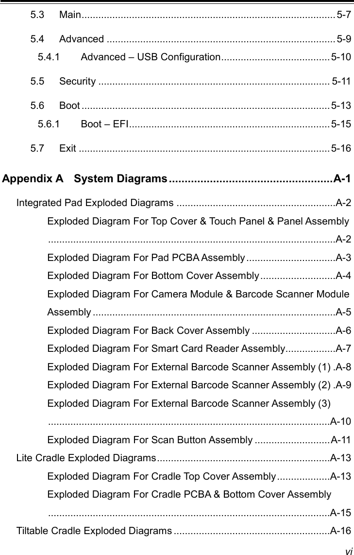
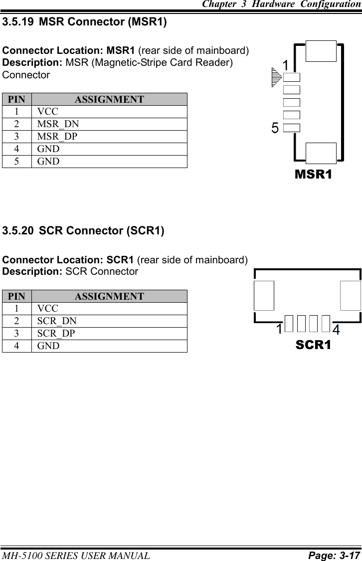
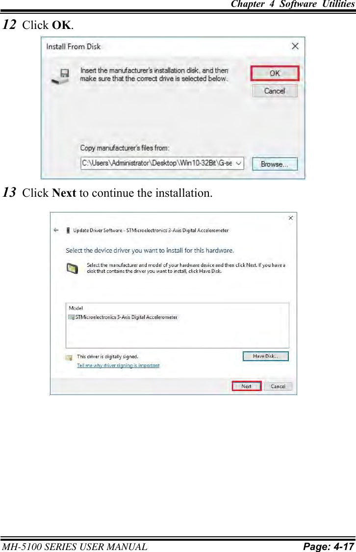
![Chapter 5 BIOS Setup MH-5100 SERIES USER MANUAL Page: 5-7 5.3 Main Menu Path Main The Main menu allows you to view the BIOS Information, change the system date and time, and view the user access privilege level. Use tab to switch between date elements. Use <↑> or <↓> arrow keys to highlight the item and enter the value you want in each item. This screen also displays the BIOS version (project) and BIOS Build Date and Time. InsydeH20 Setup Utility Rev. 5.0 Main Advanced Security Boot Exit BIOS Version 51000PTA Select the current default language used by the InsydeH20. Build Date 05/11/2017 Build Time 14:10:19 MCU Version: 170210 Processor Type System Bus Speed System Memory Speed Cache RAM Total Memory Intel® Atom™ CPU Z3736F @ 1.33 GHz 83 MHz 1333 MHz 1024 KB 2048 MBeMMC Total Size: 32 GB VGFX value: 1.00 VCore value: 0.71 VDDR value: 1.350 Language <English> System Time [10:50:39] System Date [12/14/2016] F1 Help Select Item F5/F6 Change Values F9 Setup Defaults Esc Exit Select Menu Enter Select ►SubMenu F10 Save and Exit Main Screen BIOS Setting Options Description/Purpose BIOS Version No changeable options Displays the BIOS Version. Build Date No changeable options Displays the current Build Date. Build Time No changeable options Displays the current Build Time. MCU Version No changeable options Displays the MCU Version. Processor Type No changeable options SOC Type on the platform. System Bus Speed No changeable options Displays Bus speed. System Memory Speed No changeable options Displays Memory Speed. Cache RAM No changeable options Displays Cache RAM size. Total Memory No changeable options Displays Total memory size. eMMC Total Size No changeable options Displays eMMC memory size.](https://usermanual.wiki/PORTECH-SYSTEMS/MH5100.Users-Manual/User-Guide-3641989-Page-112.png)