PORTECH SYSTEMS MH5100 10.1 inch Integrated Pad User Manual
PORTECH SYSTEMS Co.,Ltd 10.1 inch Integrated Pad Users Manual
Contents
- 1. Users Manual
- 2. User Manual
Users Manual

USER
MANUAL
MH-5100
10.1” Integrated Pad
Powered By Intel® AtomTM
MH-5100 M1

MH-5100
10.1” Integrated Pad Powered By
Intel® AtomTM
COPYRIGHT NOTICE & TRADEMARK
All trademarks and registered trademarks mentioned herein are the
property of their respective owners.
This manual is copyrighted in October 2017. You may not
reproduce or transmit in any form or by any means, electronic,
or mechanical, including photocopying and recording.
DISCLAIMER
This user’s manual is meant to assist users in installing and setting up
the system. The information contained in this document is subject to
change without any notice.
CE NOTICE
This is a class A product. In a domestic environment this product may
cause radio interference in which case the user may be required to take
adequate measures.

FCC NOTICE
This equipment has been tested and found to comply with the limits for
a Class A digital device, pursuant to part 15 of the FCC Rules. These
limits are designed to provide reasonable protection against harmful
interference when the equipment is operated in a commercial
environment. This equipment generates, uses, and can radiate radio
frequency energy and, if not installed and used in accordance with the
instruction manual, may cause harmful interference to radio
communications. Operation of this equipment in a residential area is
likely to cause harmful interference in which case the user will be
required to correct the interference at his own expense.
You are cautioned that any change or modifications to the equipment
not expressly approve by the party responsible for compliance could
void your authority to operate such equipment.
FCC Caution
Any changes or modifications not expressly approved by the party
responsible for compliance could void the user‘s authority to operate
the equipment. The antenna(s) used for this transmitter must not be
co-located or operating in conjunction with any other antenna or
transmitter.
Radiation Exposure Statement:
This equipment complies with FCC radiation exposure limits set forth
for an uncontrolled environment. End users must follow the specific
operating instructions for satisfying RF exposure compliance. This
transmitter must not be co-located or operating in conjunction with any
other antenna or transmitter.
RF Exposure Information (SAR)
This device meets the government’s requirements for exposure to radio
waves. This device is designed and manufactured not to exceed the
emission limits for exposure to radio frequency (RF) energy set by the
Federal Communications Commission of the U.S. Government.
The exposure standard employs a unit of measurement known as the
Specific Absorption Rate, or SAR. The SAR limit set by the FCC is 1.6
W/kg. Tests for SAR are conducted using standard operating positions
accepted by the FCC with the EUT transmitting at the specified power
level in different channels. The highest SAR value for the device as
reported to the FCC is 0.573 W/kg when placed next to the body.
The FCC has granted an Equipment Authorization for this device with
all reported SAR levels evaluated as in compliance with the FCC RF
exposure guidelines. SAR information on this device is on file with the
FCC and can be found under the Display Grant section of
www.fcc.gov/oet/ea/fccid after searching on FCC ID: 2AMRAMH5100.
CAUTION: Danger of explosion may occur when the battery
is incorrectly replaced. Replace the battery only with the
same or equivalent type recommended by the manufacturer.
Dispose of used batteries according to the manufacturer’s
instructions.
WARNING: Some internal parts of the system may have high
electrical voltage. We strongly recommend that only qualified
engineers are allowed to service and disassemble the
system. If any damages should occur on the system and are
caused by unauthorized servicing, it will not be covered by
the product warranty.

i
Contents
1 Introduction ......................................................................................... 1-1
1.1 About This Manual .................................................................... 1-2
2 Getting Started .................................................................................... 2-1
2.1 Package List .............................................................................. 2-2
2.2 Pad System Overview (With Built-In Barcode Scanner) ........... 2-3
2.2.1 Front View ......................................................................... 2-3
2.2.2 Rear View .......................................................................... 2-3
2.2.3 Side View ........................................................................... 2-4
2.2.4 Top View ............................................................................ 2-4
2.2.5 Bottom View ...................................................................... 2-4
2.3 Pad System Overview (With External Barcode Scanner
(optional)) .................................................................................. 2-5
2.3.1 Front View ......................................................................... 2-5
2.3.2 Rear View .......................................................................... 2-5
2.3.3 Side View ........................................................................... 2-6
2.3.4 Top View ............................................................................ 2-6
2.3.5 Bottom View ...................................................................... 2-6
2.4 Lite Cradle System Overview ................................................... 2-7
2.4.1 Front View ......................................................................... 2-7
2.4.2 Rear View .......................................................................... 2-7
2.4.3 Side View ........................................................................... 2-8
2.4.4 Top View ............................................................................ 2-8
2.4.5 Bottom View ...................................................................... 2-9
2.4.6 Quarter View .................................................................... 2-10
2.5 Tiltable Cradle System Overview ............................................ 2-11
2.5.1 Top View .......................................................................... 2-11

ii
2.5.2 Front View ....................................................................... 2-11
2.5.3 Left Side View .................................................................. 2-12
2.5.4 Right Side View ............................................................... 2-12
2.5.5 Rear View ........................................................................ 2-13
2.5.6 Bottom View .................................................................... 2-13
2.5.7 Quarter View .................................................................... 2-14
2.6 Quick Setup ............................................................................. 2-15
2.6.1 Turning the Power On from Pad and Connect to Wi-Fi ... 2-15
2.6.2 Turning the Power On and Connect to Local Network .... 2-16
2.6.3 Installing Battery for Pad ................................................. 2-18
2.6.4 Recharging Battery from Pad .......................................... 2-19
2.6.5 Recharging Battery From Lite Cradle / Tiltable Cradle .... 2-19
2.6.6 Installing Integrated Pad Onto Lite Cradle / Tiltable Cradle
......................................................................................... 2-20
2.6.7 Separating Integrated Pad From Lite Cradle / Tiltable Cradle
......................................................................................... 2-22
2.6.8 Scanning Barcodes and QR Codes ................................ 2-24
2.6.9 Installing Hand Strap ....................................................... 2-25
2.6.10 Installing Neck Strap ........................................................ 2-26
2.7 Pad Specifications ................................................................... 2-27
2.8 Lite Cradle Specifications ........................................................ 2-30
2.9 Tiltable Cradle Specifications .................................................. 2-31
2.10 OS Specifications .................................................................... 2-32
2.11 Safety Precautions .................................................................. 2-33
3 Hardware Configuration ..................................................................... 3-1
3.1 Pad Function Buttons and I/O Ports .......................................... 3-2

iii
3.1.1 Power Button ..................................................................... 3-2
3.1.2 DC-IN Port (DC-IN)............................................................ 3-2
3.1.3 USB Port (USB1) ............................................................... 3-2
3.1.4 Audio Port (CN_JACK1) .................................................... 3-3
3.2 Lite Cradle / Tiltable Cradle I/O Ports Diagram ......................... 3-4
3.2.1 Lite Cradle I/O Ports Diagram ........................................... 3-4
3.2.2 Tiltable Cradle I/O Ports Diagram ...................................... 3-4
3.3 Pad Main Board Component Locations .................................... 3-5
3.3.1 Top View of Pad Main Board Component Locations ......... 3-5
3.3.2 Bottom View of Pad Main Board Component Locations ... 3-6
3.4 Pad Main Board Connectors Quick Reference Table ................ 3-7
3.5 Setting Pad Main Board Connectors ......................................... 3-8
3.5.1 Touch Panel Connector (TOUCH1) ................................... 3-8
3.5.2 Flash Descriptor Override Selection (JP1) ........................ 3-8
3.5.3 LVDS Connector (LVDS1) ................................................. 3-9
3.5.4 RTC Battery Connector (BAT2) ....................................... 3-10
3.5.5 Earphone Jack Connector (CN_JACK1) ......................... 3-10
3.5.6 Speaker Connector (SPK1) ............................................. 3-11
3.5.7 Barcode Scanner Connector (CN_BARCODE) .............. 3-11
3.5.8 Left Scan Button (BUTTON1) .......................................... 3-12
3.5.9 Right Scan Button (BUTTON2) ....................................... 3-12
3.5.10 Power Button (BUTTON4) ............................................... 3-12
3.5.11 Battery Connector (BAT1) ............................................... 3-13
3.5.12 DC IN Jack Connector (DC_IN1) .................................... 3-13
3.5.13 Cradle Connector (CRADLE1) ........................................ 3-14
3.5.14 MCU F/W Update Connector (JP5) ................................. 3-14
3.5.15 Battery Lock Switch Button (BAT_LOCK) ....................... 3-15
3.5.16 MicroSD Card Connector (J2) ......................................... 3-15
3.5.17 CCD Front Camera Connector (CCM1) .......................... 3-16

iv
3.5.18 USB 2.0 Connector (USB1) ............................................. 3-16
3.5.19 MSR Connector (MSR1) ................................................. 3-17
3.5.20 SCR Connector (SCR1) .................................................. 3-17
3.6 Daughter Board Connectors & Jumpers Quick Reference Table ..
................................................................................................ 3-18
3.7 Daughter Board MR-5100RA-1 Connectors Location............. 3-20
3.8 Setting Daughter Board MR-5100RA-1 Connectors ............... 3-21
3.8.1 DC IN Jack Connector (DC_IN1) .................................... 3-21
3.8.2 DC Out Jack Connector (DC_OUT) ................................ 3-21
3.8.3 Universal Serial Bus 2.0 Connector (USB1) ................... 3-21
3.8.4 Universal Serial Bus 2.0 Connector (USB2) ................... 3-22
3.8.5 Universal Serial Bus 2.0 Connector (USB3) ................... 3-22
3.8.6 Universal Serial Bus 2.0 Connector (USB4) ................... 3-22
3.8.7 LAN Port (LAN1) .............................................................. 3-23
3.9 Daughter Board MR-5100RA-2 Connectors Location............. 3-24
3.10 Setting Daughter Board MR-5100RA-2 Connector ................. 3-25
3.10.1 Lite Cradle / Tiltable Cradle Connector (CRADLE1) ....... 3-25
3.11 Daughter Board MR-5100RA-3 Connectors Location............. 3-26
3.12 Setting Daughter Board MR-5100RA-3 Connectors ............... 3-27
3.12.1 Barcode Scanner Connector (CN_BARCODE1) ............ 3-27
3.12.2 Bar Code Scanner Connector (CN_BARCODE2) ........... 3-27
3.12.3 Trigger Connector (JP1) .................................................. 3-28
3.12.4 Trigger Connector (JP2) .................................................. 3-28
3.13 Daughter Board MR-5100RA-5 Connectors & Jumpers Location .
................................................................................................ 3-29
3.14 Setting Daughter Board MR-5100RA-5 Connectors and Jumpers

v
................................................................................................ 3-31
3.14.1 COM1, COM2 Port Pin9 Definition Selection Guide
(JP_COM1 and JP_COM2) ............................................. 3-31
3.14.2 RJ-45 COM Port (COM1) ................................................ 3-32
3.14.3 D-Sub 9 COM Port (COM2) ............................................ 3-32
3.14.4 DC-IN Port (DC_IN1) ....................................................... 3-33
3.14.5 Dual USB Ports ............................................................... 3-33
3.14.6 Local Area Network (LAN) Port (LAN1) ........................... 3-34
3.14.7 Cash Drawer Port (DRW1) .............................................. 3-35
3.14.8 LAN & Cash Drawer Function Switch (SW1) .................. 3-35
3.15 Daughter Board MR-5100RA-8 Connectors Location............. 3-36
3.16 Setting Daughter Board MR-5100RA-8 Connectors ............... 3-36
3.16.1 Barcode Scanner Function Switch Connector (SW1) ..... 3-36
3.16.2 Trigger Connector (JP1) .................................................. 3-36
3.16.3 Trigger Connector (JP2) .................................................. 3-36
4 Software Utilities ................................................................................. 4-1
4.1 Introduction ................................................................................ 4-2
4.2 Installing Intel® Chipset Software Installation Utility .................. 4-3
4.3 Installing Audio Realtek Software Installation Utility ................. 4-5
4.4 Installing G-Sensor Software Installation Utility ...................... 4-12
4.5 Installing Bluetooth Software Installation Utility ...................... 4-20
4.6 Cash Drawer API Function ...................................................... 4-21
5 BIOS SETUP ........................................................................................ 5-1
5.1 Introduction ................................................................................ 5-2
5.2 Accessing Setup Utility .............................................................. 5-3

vi
5.3 Main ........................................................................................... 5-7
5.4 Advanced .................................................................................. 5-9
5.4.1 Advanced – USB Configuration ....................................... 5-10
5.5 Security ................................................................................... 5-11
5.6 Boot ......................................................................................... 5-13
5.6.1 Boot – EFI ........................................................................ 5-15
5.7 Exit .......................................................................................... 5-16
Appendix A System Diagrams .................................................... A-1
Integrated Pad Exploded Diagrams .........................................................A-2
Exploded Diagram For Top Cover & Touch Panel & Panel Assembly
.......................................................................................................A-2
Exploded Diagram For Pad PCBA Assembly ................................A-3
Exploded Diagram For Bottom Cover Assembly ...........................A-4
Exploded Diagram For Camera Module & Barcode Scanner Module
Assembly .......................................................................................A-5
Exploded Diagram For Back Cover Assembly ..............................A-6
Exploded Diagram For Smart Card Reader Assembly ..................A-7
Exploded Diagram For External Barcode Scanner Assembly (1) .A-8
Exploded Diagram For External Barcode Scanner Assembly (2) .A-9
Exploded Diagram For External Barcode Scanner Assembly (3)
.....................................................................................................A-10
Exploded Diagram For Scan Button Assembly ........................... A-11
Lite Cradle Exploded Diagrams ..............................................................A-13
Exploded Diagram For Cradle Top Cover Assembly ...................A-13
Exploded Diagram For Cradle PCBA & Bottom Cover Assembly
.....................................................................................................A-15
Tiltable Cradle Exploded Diagrams ........................................................A-16

vii
Exploded Diagram For Base Bottom Cover Assembly ................A-16
Exploded Diagram For Rotation Cover Assembly .......................A-18
Exploded Diagram For Base Top Cover Assembly .....................A-20
Exploded Diagram For Pad Lock Assembly ................................A-21
Exploded Diagram For Holder Back Cover Assembly .................A-22
Exploded Diagram For Holder Top Cover Assembly ...................A-24
Exploded Diagram For Card Holder Assembly ...........................A-26
Appendix B Technical Summary ................................................ B-1
Interrupt Map ............................................................................................B-2
I/O Map ...................................................................................................B-16
Memory Map ...........................................................................................B-18
System BIOS Update Procedure ............................................................B-20

viii
Revision History
The revision history of MH-5100 User Manual is described below:
Version No.
Revision History
Date
1.0
Initial Release
09/06/2017

MH-5100 SERIES USER MANUAL
Page: 1-1
1Introduction
This chapter provides the introduction for the MH-5100
system as well as the framework of the user manual.
The following topic is included:
•About This Manual

Chapter 1 Introduction
MH-5100 SERIES USER MANUAL
Page: 1-2
1.1 About This Manual
Thank you for purchasing our MH-5100 system. The MH-5100 provides faster
processing speed, greater expandability and can handle more tasks than before. This
manual is designed to assist you how to install and set up the whole system. It
contains 5 chapters and 2 appendixes. Users can configure the system according to
their own needs. This user manual is intended for service personnel with strong
hardware background. It is not intended for general users.
The following section outlines the structure of this user manual.
Chapter 1 Introduction
This chapter provides the introduction for the MH-5100 system as well as the
framework of the user manual.
Chapter 2 Getting Started
This chapter describes the package contents and outlines the system specifications. It
also includes the physical illustrations and quick setup for the MH-5100 system. Read
the safety reminders carefully on how to take care of your system properly.
Chapter 3 System Configuration
This chapter outlines the locations of the motherboard and daughter board
components and their respective functions. You will learn how to set the jumpers and
configure the system to meet your own needs.
Chapter 4 Software Utilities
This chapter contains helpful information for proper installations of the Intel Chipset
Software Installation Utility, Audio Realtek Driver Utility, G-Sensor Driver
Utility, Bluetooth Driver Utility and Cash Drawer API reference.
Chapter 5 BIOS Setup
This chapter indicates how to change the BIOS configurations.
Appendix A System Assembly Diagrams
This appendix provides the exploded diagrams and part numbers of the MH-5100.
Appendix B Technical Summary
This appendix provides the information about the allocation maps for system
resources and System BIOS update procedure.

MH-5100 SERIES USER MANUAL
Page: 2-1
2Getting Started
This chapter provides the information for MH-5100 system.
In addition to the MH5100 Pad, users are also welcome to
purchase the optional devices. This chapter describes
the package contents, system overview and outlines the
system specifications.
The following topics are included:
•Package List
•Pad System Overview
•Lite Cradle System Overview
•Tiltable Cradle System Overview
•Quick Setup
•Pad Specifications
•Lite Cradle Specifications
•Tiltable Cradle Specifications
•Safety Precautions
Experienced users can go to Chapter 3 Hardware
Configuration on page 3-1 for a quick start.
Chapter 2 Getting Started
MH-5100 SERIES USER MANUAL
Page: 2-2
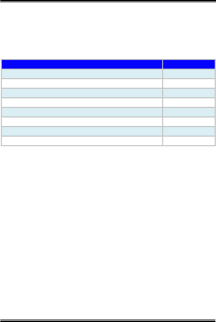
2.1 Package List
If you discover any of the items listed below are damaged or lost,
please contact your local distributor immediately.
Item
Q’ty
MH-5100 Integrated Pad
1
Quick Reference Guide
1
AC Power Adapter for Pad
1
Hand Strap (optional)
1
Neck Strap (optional)
1
Lite Cradle (optional)
1
Power Adapter for Lite Cradle (optional)
1
Power Cord for Lite Cradle (optional)
1
Chapter 2 Getting Started
MH-5100 SERIES USER MANUAL
Page: 2-3
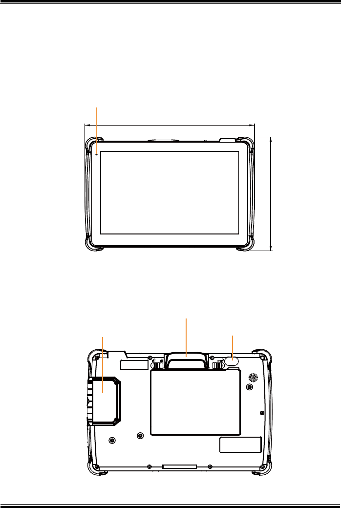
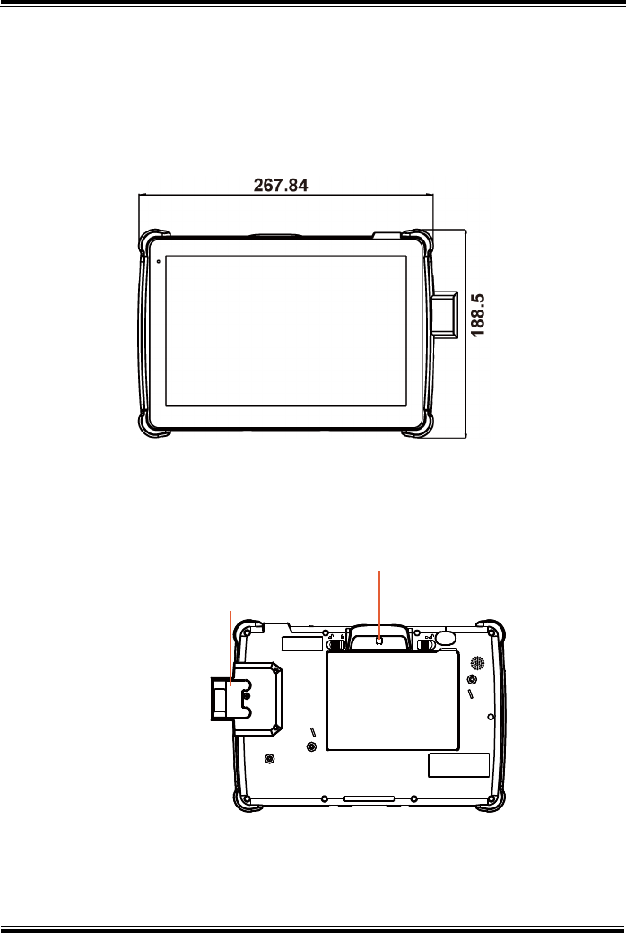
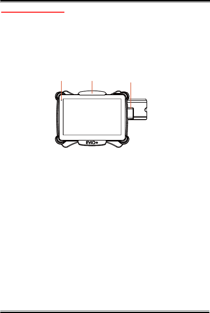
2.2 Pad System Overview (With Built-In
Barcode Scanner)
Unit: mm
2.2.1 Front View
2.2.2 Rear View
Power LED
267.84
188.5
MSR
Smart Card Reader Camera
Battery Pack
Chapter 2 Getting Started
MH-5100 SERIES USER MANUAL
Page: 2-4
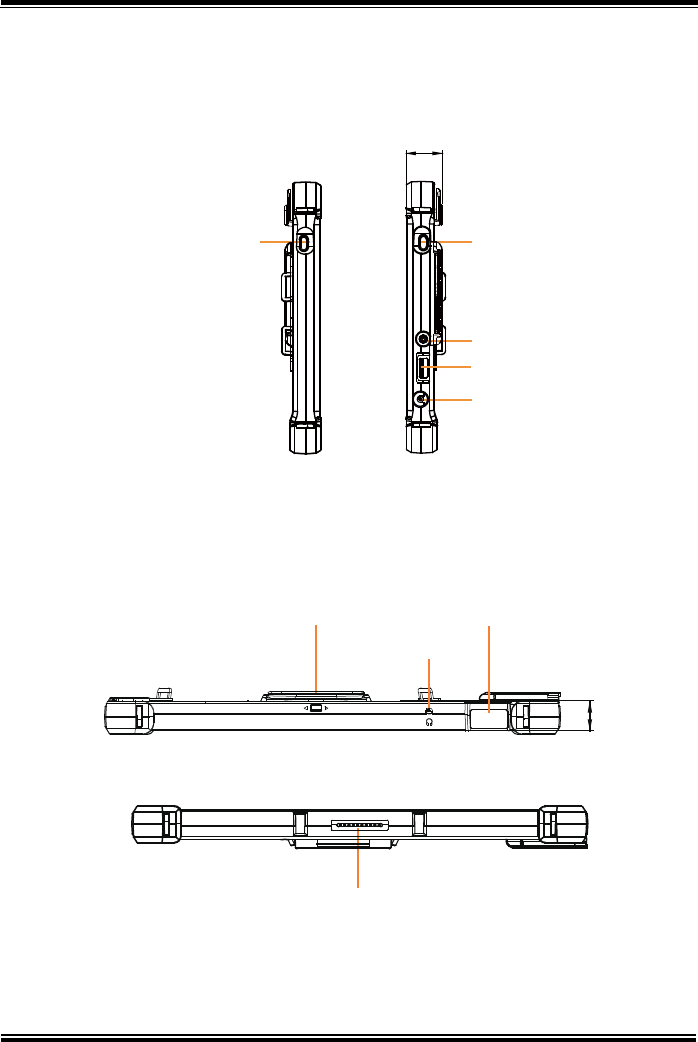
2.2.3 Side View
2.2.4 Top View
2.2.5 Bottom View
Scan Button Scan Button
Power Button
USB Port
DC-IN
25.2
17.7
MSR Built-in Barcode Scanner
Earphone Jack
POGO Pins
Chapter 2 Getting Started
MH-5100 SERIES USER MANUAL
Page: 2-5
Unit: mm
2.3.1 Front View
2.3.2 Rear View
Scan Button
External Barcode
Scanner (optional)
Battery Pack
2.3 Pad System Overview (With External Barcode
Scanner (optional))

Chapter 2 Getting Started
MH-5100 SERIES USER MANUAL
Page: 2-6
2.3.3 Side View
2.3.4 Top View
2.3.5 Bottom View
25.2
Scan Button Scan Button
External Barcode Scanner
Power Button
USB Port
DC-IN
Chapter 2 Getting Started
MH-5100 SERIES USER MANUAL
Page: 2-7
Unit: mm
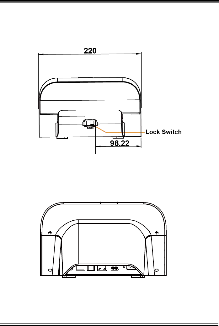
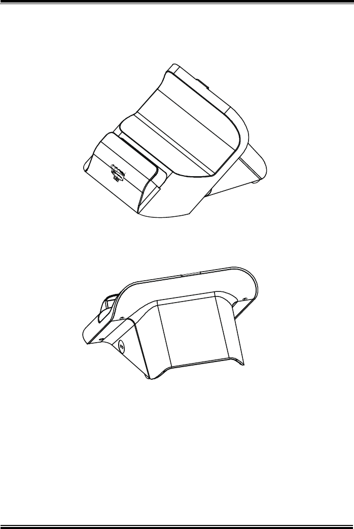
2.4.2 Rear View
IN 12V COM DWR LAN USB COM
2.4 Lite Cradle System Overview
2.4.1 Front View
Chapter 2 Getting Started
MH-5100 SERIES USER MANUAL
Page: 2-8
2.4.3 Side View
2.4.4 Top View
Kensington
Lock Slot
217.23
131.65
Chapter 2 Getting Started
MH-5100 SERIES USER MANUAL
Page: 2-9
2.4.5 Bottom View
LAN and Cash Drawer Selection
DWR LAN
Chapter 2 Getting Started
MH-5100 SERIES USER MANUAL
Page: 2-10
2.4.6 Quarter View
Chapter 2 Getting Started
MH-5100 SERIES USER MANUAL
Page: 2-11
Unit: mm
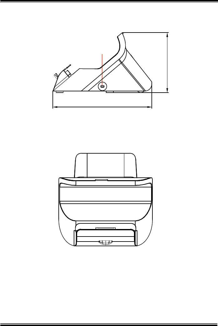
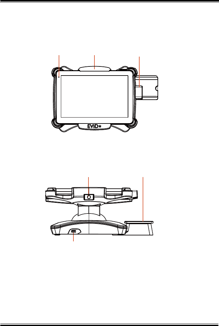
2.5.2 Front View
2.5 Tiltable Cradle System Overview
2.5.1 Top View
Power LED External
Barcode Scanner
Pad Lock
USB1
USB1
Card HolderRelease Switch
Chapter 2 Getting Started
MH-5100 SERIES USER MANUAL
Page: 2-12
2.5.3 Left Side View
2.5.4 Right Side View
LAN1
USB4 LAN1 USB3 USB2
USB3
USB2
USB4
DC-OUT
DC-OUT
DC-IN
12V
DC-IN 12V
Kensington slot
152.86
135.59
Chapter 2 Getting Started
MH-5100 SERIES USER MANUAL
Page: 2-13
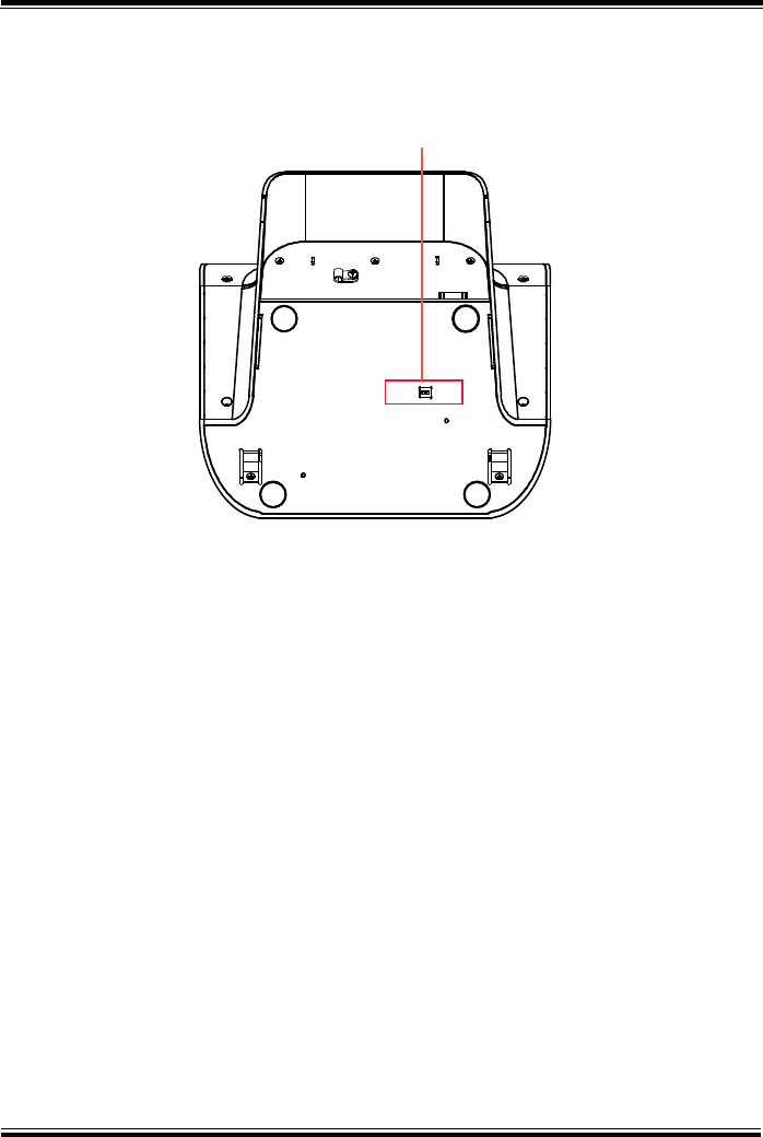
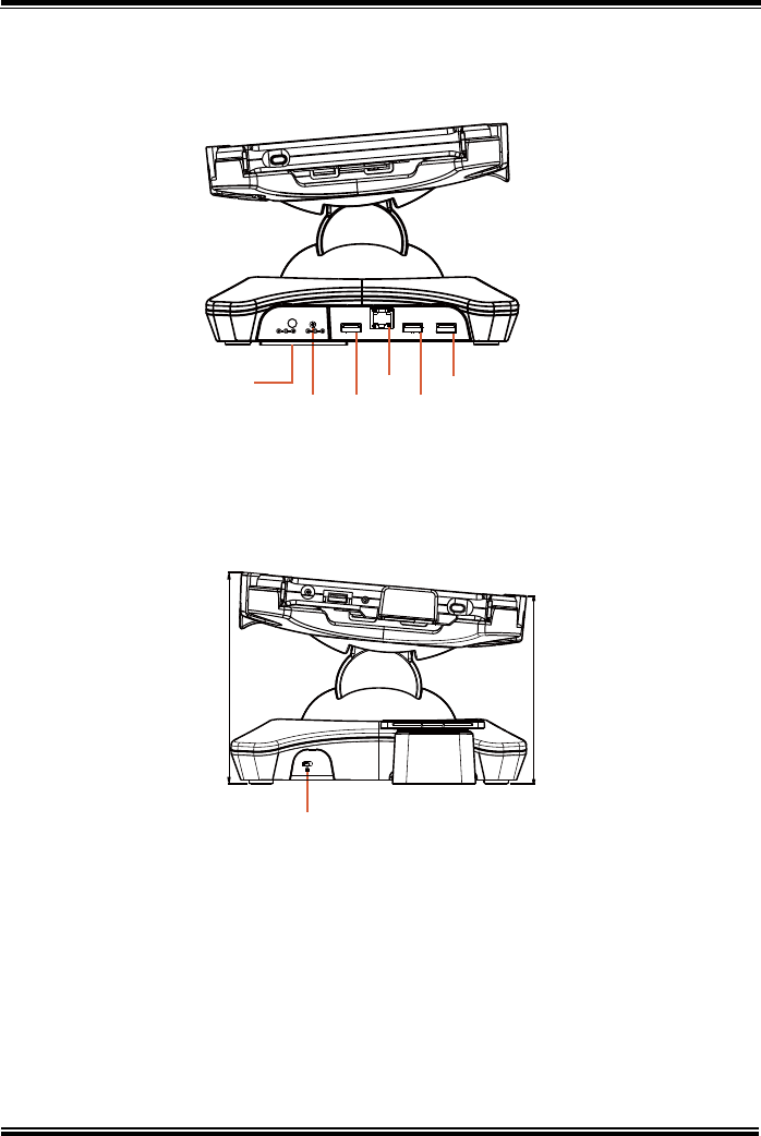
2.5.5 Rear View
2.5.6 Bottom View
Chapter 2 Getting Started
MH-5100 SERIES USER MANUAL
Page: 2-14
2.5.7 Quarter View

Chapter 2 Getting Started
MH-5100 SERIES USER MANUAL
Page: 2-15
2.6 Quick Setup
2.6.1 Turning the Power On from Pad and Connect to Wi-Fi
Long press the Power Button on the right side of the Pad to turn on the
system. Connect the Pad to a wireless network via Wi-Fi connection. (Refer to
the Side View section of Pad for the location of Power Button.)
How to Set Up Wi-Fi Connection
Step 1. From the bottom right corner of the screen, tap the icon from the
tool tray.
Step 2. From the small pop-up window, tap on the Wi-Fi icon if it shows
grey to activate Wi-Fi.
Step 3. Select a Wi-Fi network from the list and tap on it.
Step 4. Tap the Connect button.
Step 5. Enter the correct security key for the selected Wi-Fi network and wait
for the Wi-Fi connection to establish.
You can also swipe the screen from the right side of the Pad to bring up the
ACTION CENTER window and select Network menu item to enter the Wi-Fi
network selection list.
For stability issue, always power off the Pad from Windows 10 OS. Make sure
you have closed all the application programs before you close Windows. Tap
on Start icon from the bottom left corner of the Pad and select the
displayed menu icon and select Shut down from the selection list to turn
off the Pad power.
Chapter 2 Getting Started
MH-5100 SERIES USER MANUAL
Page: 2-16
2.6.2 Turning the Power On and Connect to Local Network
For Lite Cradle
Prerequisite: Insert a ball point pen or a pin into the hole of DWR/LAN
selection switch slot located on the bottom base of the Lite Cradle, and switch
it to the LAN port location. See the picture below:
Press the Power Button on the right side of the Pad to turn on the system.
Connect the Ethernet cable to the LAN port on the rear side of the Lite Cradle
and the other end of the network cable to a port on your hub, switch or router.
(Refer to the Side View section of Pad (With Built-In Barcode Scanner) for the
location of Power Button.) Refer to the Lite Cradle I/O Ports Diagram
section for the location of LAN port.
LAN and Cash Drawer Selection
DWR LAN

Chapter 2 Getting Started
MH-5100 SERIES USER MANUAL
Page: 2-17
For Tiltable Cradle
Press the Power Button on the right side of the Pad to turn on the system.
Connect the Ethernet cable to the LAN port on the bottom left side of the
Tiltable Cradle and the other end of the network cable to a port on your hub,
switch or router. (Refer to the Side View section of Pad (with External
Barcode Scanner (optional)) for the location of Power Button.) Refer to the
Tiltable I/O Ports Diagram section for the location of LAN port.
Chapter 2 Getting Started
MH-5100 SERIES USER MANUAL
Page: 2-18
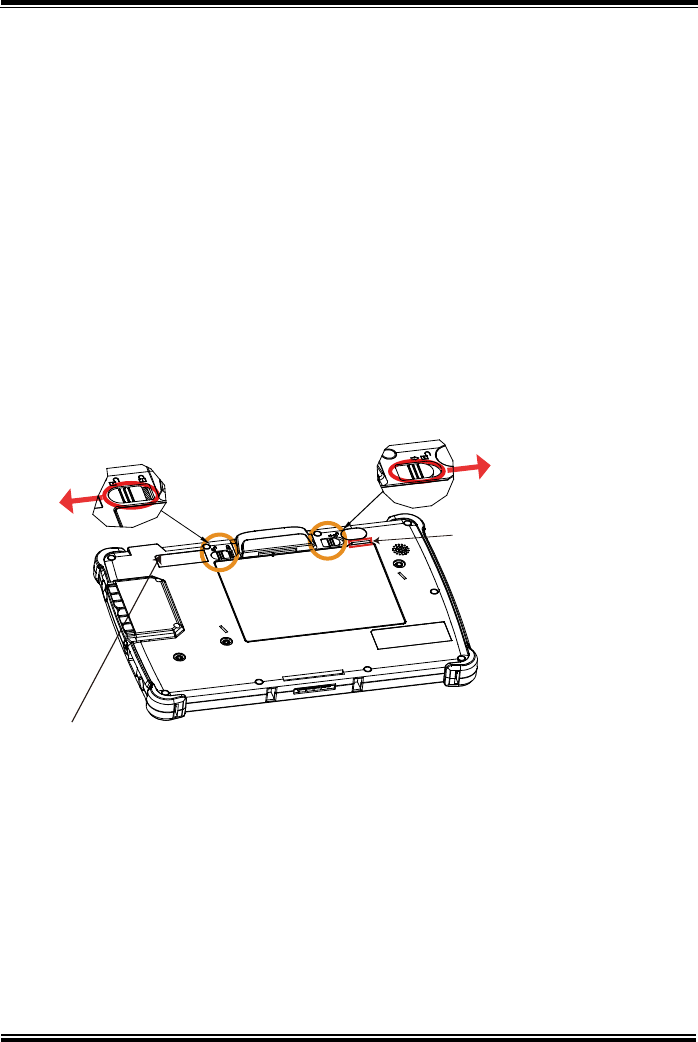
2.6.3 Installing Battery for Pad
Make sure to power off the device first before you start installing the battery.
Step 1. Slide to unlock the left-side battery switch with your left hand. See
the Figure below.
Step 2. Use your left hand to push the right-side sliding tab to the right and
long press on it and hold it.
Step 3. Use a fingertip of your right hand to remove the battery from the slim
opening located under the Camera.
Step 4. Replace a new battery onto the back of Pad and the right-side
locking switch snaps into place automatically.
Step 5. Slide the left-side battery switch to the right to secure and lock up the
replaced battery.
Note 1: The factory default battery cycle life guarantees to retain 80 percent of its original
capacity after the battery has been charged and discharged for 300 times.
Note 2: Batteries are consumerables and the limited warranty for MH-5100 battery is 1 year
only.
Step 1. Use your left hand to
slide to unlock left-side
battery switch.
Step 2. Push sliding tab to
the right side
and long press
on it and hold it.
Step 3. Use a fingertip of your right hand
to remove the battery from the slim
opening.
Step 4. Replace a new battery onto back
of Pad and the right-side locking
switch snaps into place
automatically.
Step 5. Slide the left-side
battery switch to the
right to secure and
lock up the replaced battery
to complete.

Chapter 2 Getting Started
MH-5100 SERIES USER MANUAL
Page: 2-19
Low Battery Indicator
The low battery indicator will show on the LCD screen when the battery is
nearly exhausted. When the low battery indicator appears on the tool tray, you
should recharge the battery by connecting the power adapter of Pad/Lite
Cradle/Tiltable Cradle or replace a fully charged battery immediately.
2.6.4 Recharging Battery from Pad
Before you use MH-5100 Pad, follow the instructions below to charge the
battery:
Step 1. Connect the Pad’s AC power adapter to the DC-IN jack located on
the right side of the Pad. (Refer to the Side View section of Pad for
the location of the DC-IN Jack.)
Step 2. Plug the other end to an AC power outlet.
MH-5100 Pad battery will then start charging, and the Power LED indicator on
the top left corner of the touch screen will then flash GREEN. After the battery
is fully charged, the Power LED indicator will turn to a solid green.
2.6.5 Recharging Battery From Lite Cradle / Tiltable Cradle
Lite Cradle
Step 1. Connect the Lite Cradle’s AC power adapter to the DC-IN power jack
located on the bottom of the Lite Cradle.
Step 2. Plug the other end to an AC power outlet.
Tiltable Cradle
Step 1. Connect the Tiltable Cradle’s AC power adapter to the DC-IN power
jack located on the bottom left side of the Tiltable Cradle.
Step 2. Plug the other end to an AC power outlet.
The Power LED indicator on the top left corner of the touch screen will then
flash GREEN. After the battery is fully charged, the Power LED indicator will
turn to a solid green.
Chapter 2 Getting Started
MH-5100 SERIES USER MANUAL
Page: 2-20
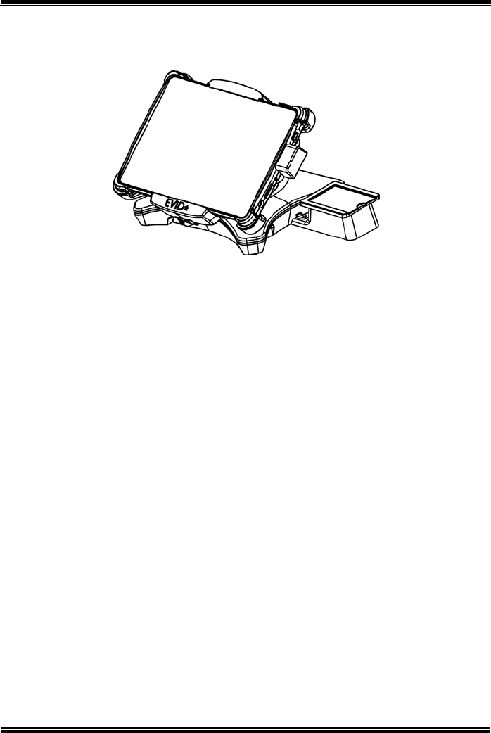
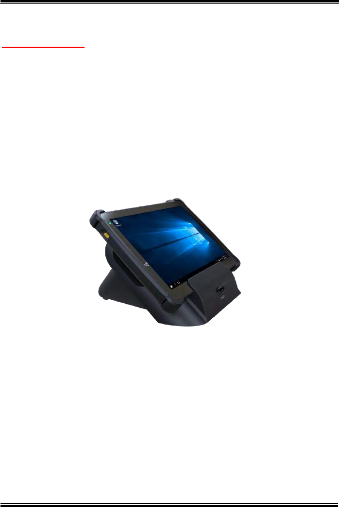
2.6.6 Installing Integrated Pad Onto Lite Cradle / Tiltable Cradle
For Lite Cradle
Step 1. From the bottom side of Pad, align the two locking tabs located
on both side of the POGO pins to their mating slots located inside
of Lite Cradle base respectively.
Step 2. Lock the two locking tabs of Pad into their mating slots inside the
Lite Cradle base and the Pad snaps into place.
Step 3. The installation is completed.
Chapter 2 Getting Started
MH-5100 SERIES USER MANUAL
Page: 2-21
For Tiltable Cradle
Step 1. Place Integrated Pad into Tiltable Cradle.
Step 2. Push down the Pad Lock from the top side of the Tiltable Cradle
and the Pad snaps into place. See the picture below.
Step 3. The installation is completed.
External
Barcode Scanner
Power LED Pad Lock
Chapter 2 Getting Started
MH-5100 SERIES USER MANUAL
Page: 2-22
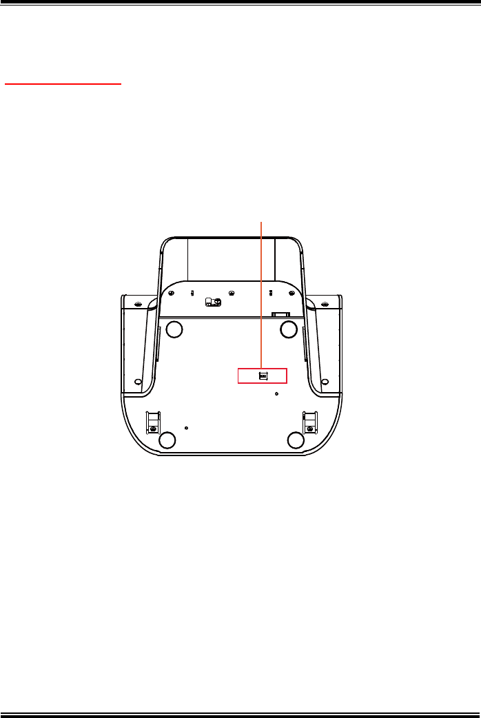
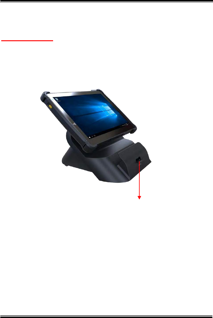
2.6.7 Separating Integrated Pad From Lite Cradle / Tiltable Cradle
For Lite Cradle
Step 1. Push down the Lock Switch on the front of Lite Cradle.
Step 2. Separate the integrated pad from the lite cradle. See the picture
below:
Push down the Lock Switch to eject.
Chapter 2 Getting Started
MH-5100 SERIES USER MANUAL
Page: 2-23
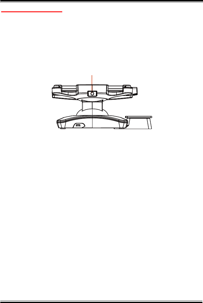
For Tiltable Cradle
Step 1. Push upwards the Release Switch located on the bottom side of
Tiltable Cradle. The Pad Lock on the top side of Tiltable Cradle will
then release. See the System Top View picture below for the
location of Release Switch.
Step 2. Separate the integrated pad from the Tiltable Cradle.
USB1
Release Switch
Chapter 2 Getting Started
MH-5100 SERIES USER MANUAL
Page: 2-24
2.6.8 Scanning Barcodes and QR Codes
From Pad With Built-In Barcode Scanner
Step 1. Press to turn on the Scan Button located on the right/left side of the
Pad. (Refer to the Side View section of Pad for the location of the
Scan Button.)
Step 2. Point the Barcode Scanner at the barcode or QR code that you
want to scan and position the light beam on the barcode/QR code.
(Refer to the Top View section of Pad for the location of the Barcode
Scanner.)
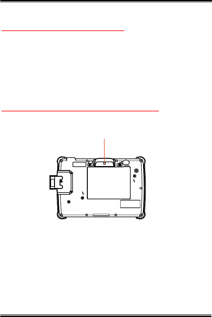
From Pad With External Barcode Scanner (optional)
Step 1. Press Scan Button located above the battery pack on the rear
top of Pad. See the picture below:
Or you can press Scan Button located on the right/left of Pad. (Refer
to the Side View section of Pad (With External Barcode Scanner
(optional)) for the location of the Scan Button.)
Step 2. Point the External Barcode Scanner at the barcode or QR code
that you want to scan and position the light beam on the barcode/QR
code.
After the barcode/QR code has been scanned successfully, you will hear one
beep sound.
Scan Button
Battery Pack

Chapter 2 Getting Started
MH-5100 SERIES USER MANUAL
Page: 2-25
2.6.9 Installing Hand Strap
Step 1. Tighten the two screws of the strap bracket set onto the strap bracket
holes on the back cover.
Step 2. Ready to hold the hand strap attached on the strap brackets to lift up
the Pad with your hand.
Note: The strap bracket set is pre-installed for easy user installation before
the shipment. The strap bracket set includes 2 x strap brackets, 2 x
pan head screws (M3 x 6 mm) and 1 x Velcro badge.
Chapter 2 Getting Started
MH-5100 SERIES USER MANUAL
Page: 2-26
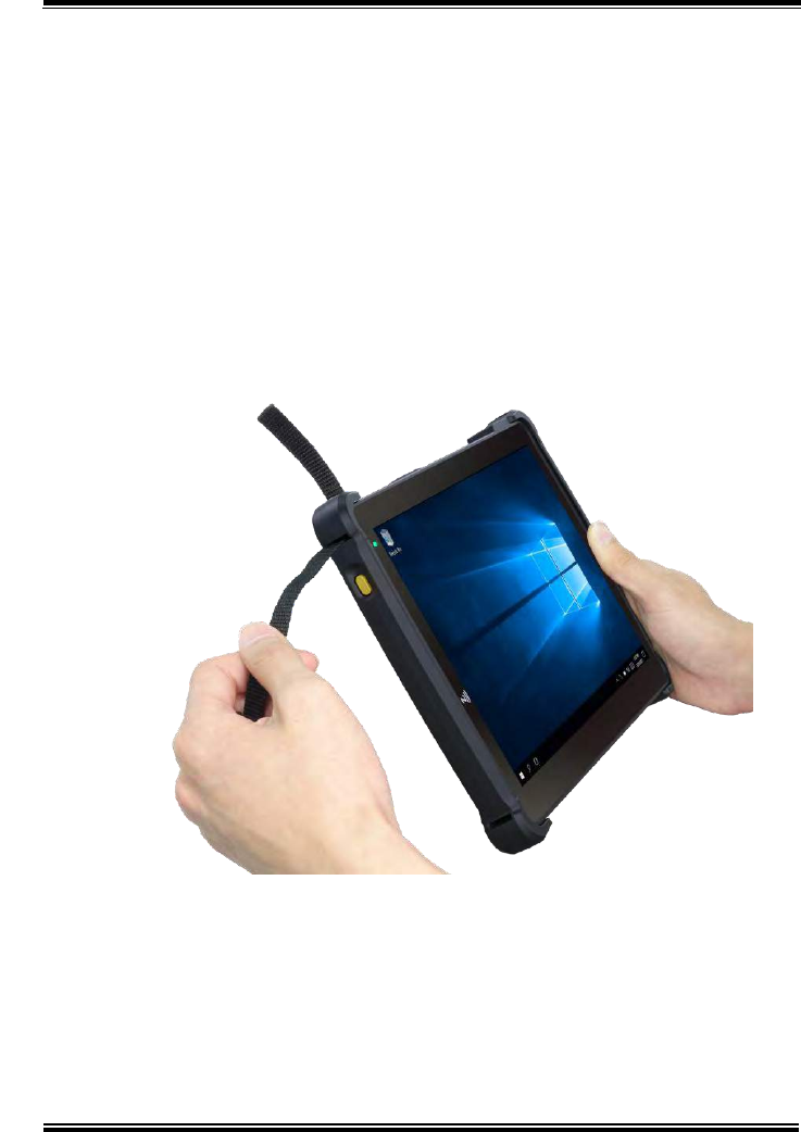
2.6.10 Installing Neck Strap
Step 1. Insert one end of the provided neck strap through the upper opening
of the right-side bumper rubber and adjust to tighten the neck strap.
Step 2. Insert another end of the neck strap through the upper opening of the
left-side bumper rubber and adjust to tighten the neck strap.
Step 3. Put the installed neck strap around your neck to carry the Pad
around.
Note: You can also select to put the neck strap through the lower openings of
the right-side and left-side bumper rubbers.

Chapter 2 Getting Started
MH-5100 SERIES USER MANUAL
Page: 2-27
2.7 Pad Specifications
Fundamental Spec. (Conform to RoHS Directive)
Operator
Display (LCD)
Type
10.1” LCD
Resolution
WXGA 1280 x 800 dots
Brightness
Typical 400 cd/m2
Life time of Backlight
Lamp
30,000 hours
Interface
LVDS
Backlight
Type
LED Backlight
Touch Panel
Type
10.1” PCT
Interface
I2C
CPU
BGA on board CPU
Intel® Atom™ Z3736F Processor
Base Frequency: 1.33 GHz Up to 1.83 GHz
Chipset
Intel Platform
Built-in CPU
Memory
DDR3L on Board
2GB DDR3L
PMIC
Type
TI
Interface
I2C
Charger
Type
TI
Interface
I2C
Storage (eMMC)
Type
32GB/64GB
Interface
SDIO
Storage (SD)
Type
MicroSD Slot
Interface
SDIO
BIOS
Insyde BIOS
SPI Flash ROM
Hardware
Monitor
Type
(1) Voltage detection (Battery)
(2) CPU & System Temperature detection
(3) CPU Temperature over heat warning
(4) CPU Temperature over heat shut down
Speaker
Type
1W Speaker x1
Wi-Fi +
Bluetooth
Module IC
Type
802.11 b/g/n wireless LAN and Bluetooth 4.0
module
Interface
Wi-Fi: SDIO / Bluetooth: UART

Chapter 2 Getting Started
MH-5100 SERIES USER MANUAL
Page: 2-28
G-Sensor
(Accelerator
sensor)
Type
ST
Interface
I2C
LED Indicator
Tri-color Light LED
Green / Yellow / Red
LED
1. Power LED (Green):
a. Start OSconstant Green light
b. Charging flashing Green light
c. Full chargeconstant Green light
2. Alarm LED (Yellow):
a. 14%< Battery Capacity <
8%flashing Yellow light
b. Battery Capacity < 4%system turns
to SleepYellow Alarm LED turns
OFF.
3. Error LED (Red):
a. S0 unlock battery switchflashing
Red light
b. Battery errorflashing Red light
Power Supply
Type
DC 12V/2A/24W for DC-IN / Cradle
Operating
System
OS
Windows 10 IoT Enterprise LTSB 2016 OS
(32 bits)
Dimension
L x W x T
259.9mm x 175.9mm x 17.7mm
Weight
Pad only
838g (without any optional devices attached)
Certificate
-
FCC/CE
Battery Pack
Operation time
Main battery(1S2P)
8 hours @ 7900mAh
Sub Battery
RTC Battery
160mAh
Battery Pack
Charging time
Main battery
Power ON: 5 hours
Power OFF: 4 hours
IP Rating
Body unit
IP54 (front panel only)
Drop Impact
Resistance
-
1.2m
Temperature
Operating
Temperature
0°C ~ 40°C (32°F ~ 104°F)
Storage Temperature
-20°C ~ 60°C (-4°F ~ 140°F)
Humidity
Operating Humidity
0~90%RH (no condensation)
Storage Humidity
0~95%RH (no condensation)

Chapter 2 Getting Started
MH-5100 SERIES USER MANUAL
Page: 2-29
Devices (Optional)
Built-in
Barcode
Scanner
Type
Honeywell 2D Barcode scanner
Interface
UART
External
Barcode
Scanner
Type
Honeywell 2D Barcode scanner
Interface
UART
Rear Camera
Type
5M pixels module with autofocus function
Interface
USB
MSR Module
Type
Secure head MSR (optional)
(meet ISO 7811, support AAMVA / JIS II format,
support single / dual / triple tracks)
Interface
USB
Smart Card
Reader Module
Type
Smart Card Reader (optional)
(meet ISO 7816 & EMV Level 1 & 2
Certification)
Interface
USB
External I/O Ports
DC-IN Jack
Type
DC-IN Jack x 1
Cradle
Connector
Type
POGO pins (1x10 pins) x 1
USB
Type
Standard USB (Type A) x1 for external
expansion
SD
Type
MicroSD Slot for internal memory expansion
Audio Jack
Type
Audio Jack (3.5mm) x1
External Buttons (for side I/O & front panel)
Power Button
Type
Power Button x1
Scan Button
Type
2 x Scan buttons (left and right)
1 x Scan button (rear top, optional)
Chapter 2 Getting Started
MH-5100 SERIES USER MANUAL
Page: 2-30
2.8 Lite Cradle Specifications
Lite Cradle
Cradle
Connector
Type
POGO pins (1 x 10 pins) x 1
Interface
USB 2.0/Power/GND
DC-IN Jack
Type
DC 12V IN x 1
USB
Type
Standard USB 2.0 port (Type A) x 2
COM
Type
RJ-45 with 12V/5V/RI x 1
COM
Type
D-Sub 9 with 12V/5V/RI x 1
LAN
(10/100 Mbps) or
DWR
(Cash Drawer)
Type
RJ-45 x 1
Type
RJ-11 with 12V/1A x 1
DIP Switch
-
LAN Port and Cash Drawer selection
Kensington
Security
Lock Slot
Type
1
Lock Switch
-
Fixing between Integrated Pad and Cradle
AC Power
Adapter
Type
12V/5A/60W AC Power Adapter x 1
Dimension
L x W x T
220 x 217.23 x 131.65mm
Weight
Lite Cradle only
About 858g
Note: The functions of Ethernet LAN & Cash Drawer are co-layout and can be
selected by DIP Switch.
DC-IN RJ-45 Cash LAN 2 x D-Sub 9
Drawer USB 2.0
DIP
Switch
Chapter 2 Getting Started
MH-5100 SERIES USER MANUAL
Page: 2-31
2.9 Tiltable Cradle Specifications
Tiltable Cradle
Cradle
Connector
Type
POGO pins (1 x 10 pins) x 1
Interface
USB 2.0/Power/GND
DC-IN Jack
Type
DC 12V In x 1
DC-Out Jack
Type
DC 8.4V Out x 1
USB
Type
Standard USB 2.0 port (Type A) x 4
LAN
(10/100 Mbps)
Type
RJ-45 x 1
Kensington
Security
Lock Slot
Type
1
AC Power
Adapter
Type
12V/5A/60W AC Power Adapter x 1
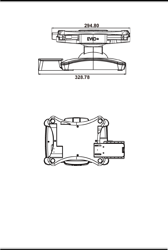
Dimension
L x W x T
328.78mm x 213.35mm x 152.86mm
Weight
Tiltable Cradle only
About 1.67 kg
USB4 LAN1 USB3 USB2DC-IN 12V DC-OUT
USB2
USB3
LAN1
USB4
DC-IN
12V
DC-OUT

Chapter 2 Getting Started
MH-5100 SERIES USER MANUAL
Page: 2-32
2.10 OS Specifications
OS
Description
Windows® 10 IoT Enterprise LTSB 2016
Supports 32 bits

Chapter 2 Getting Started
MH-5100 SERIES USER MANUAL
Page: 2-33
2.11 Safety Precautions
Before operating this system, read the following information carefully to protect your
systems from damages, and extend the life cycle of the system.
1. Check the Line Voltage
•The operating voltage for the power supply should be within the range of
100V to 240V AC; otherwise the system may be damaged.
2. Environmental Conditions
•Place your MH-5100 on a sturdy, level surface. Be sure to allow enough
space around the system to have easy access needs.
•Avoid installing your MH-5100 system in extremely hot or cold places.
•Avoid direct sunlight exposure for a long period of time (for example, in a
closed car in summer time. Also avoid the system from any heating device.).
Or do not use MH-5100 when it has been left outdoors in a cold winter day.
•Avoid moving the system rapidly from a hot place to a cold place, and vice
versa, because condensation may occur inside the system.
•Protect your MH-5100 from strong vibrations which may cause hard disk
failure.
•Do not place the system too close to any radio-active device. Radio-active
device may cause signal interference.
•Always shut down the operating system before turning off the power.
3. Handling
•Avoid placing heavy objects on the top of the system.
•Do not allow any objects to fall into this device.
•If water or other liquid spills into the device, unplug the power cord
immediately.
4. Good Care
•When the outside case gets stained, remove the stains using neutral washing
agent with a dry cloth.
•Never use strong agents such as benzene and thinner to clean the surface of
the case.
•If heavy stains are present, moisten a cloth with diluted neutral washing
agent or alcohol and then wipe thoroughly with a dry cloth.
•If dust is accumulated on the case surface, remove it by using a special
vacuum cleaner for computers.

MH-5100 SERIES USER MANUAL
Page: 3-1
3Hardware Configuration
This chapter contains helpful information about the jumper
& connector settings, and component locations.
The following sections are included:
•Pad Function Buttons and I/O Ports
•Lite Cradle / Tiltable Cradle I/O Ports Diagrams
•Pad Main Board Component Locations
•Pad Main Board Connectors Quick Reference Table
•Setting Pad Main Board Connectors
•Setting Daughter Board MR-5100RA-1 Connectors
•Setting Daughter Board MR-5100RA-2 Connector
•Setting Daughter Board MR-5100RA-3 Connectors
•Setting Daughter Board MR-5100RA-5 Connectors
and Jumpers
•Setting Daughter Board MR-5100RA-8 Connectors
Chapter 3 Hardware Configuration
MH-5100 SERIES USER MANUAL
Page: 3-2
3.1 Pad Function Buttons and I/O Ports
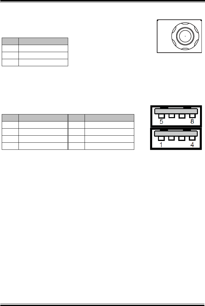
3.1.1 Power Button
To turn on the system, press the Power Button on the right side
of the Pad briefly.
ACTION
ASSIGNMENT
Press
0V
Release
+2.8V
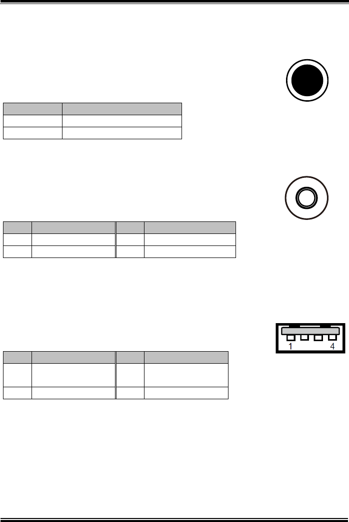
3.1.2 DC-IN Port (DC-IN)
Port Name: DC-IN
Description: DC Power-In Port. The DC-IN Port is located
on the right side of the Pad.
PIN
ASSIGNMENT
PIN
ASSIGNMENT
0
+12V
2
GND
1
+12V
3
GND
3.1.3 USB Port (USB1)
Port Name: USB1
Description: USB Type A Port (Side I/O)
PIN
ASSIGNMENT
PIN
ASSIGNMENT
1
+5V (Max.
current: 0.5A)
3
D+
2
D-
4
GND
Note: The USB1 port is provided with Standby power 5V.
Power
Button
DC-IN
USB1

Chapter 3 Hardware Configuration
MH-5100 SERIES USER MANUAL
Page: 3-3
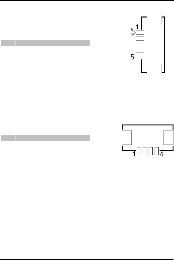
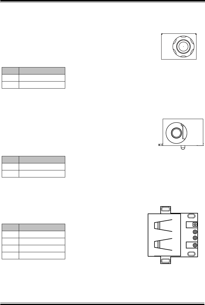
3.1.4 Audio Port (CN_JACK1)
Port Name: CN_JACK1
Description: Audio Port located on the top right side
of the Pad.
PIN
ASSIGNMENT
1
LEFT
2
RIGHT
3
GND
4
MIC
5
HP_DET
CN_JACK1
Chapter 3 Hardware Configuration
MH-5100 SERIES USER MANUAL
Page: 3-4
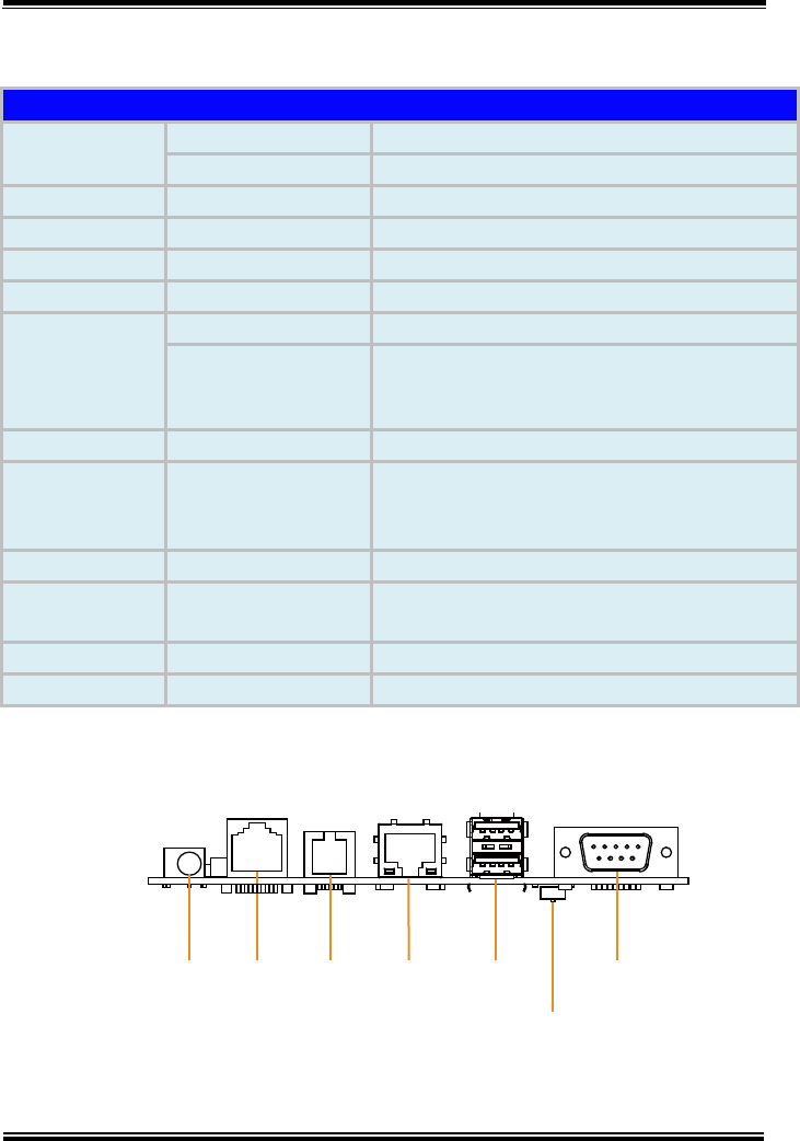
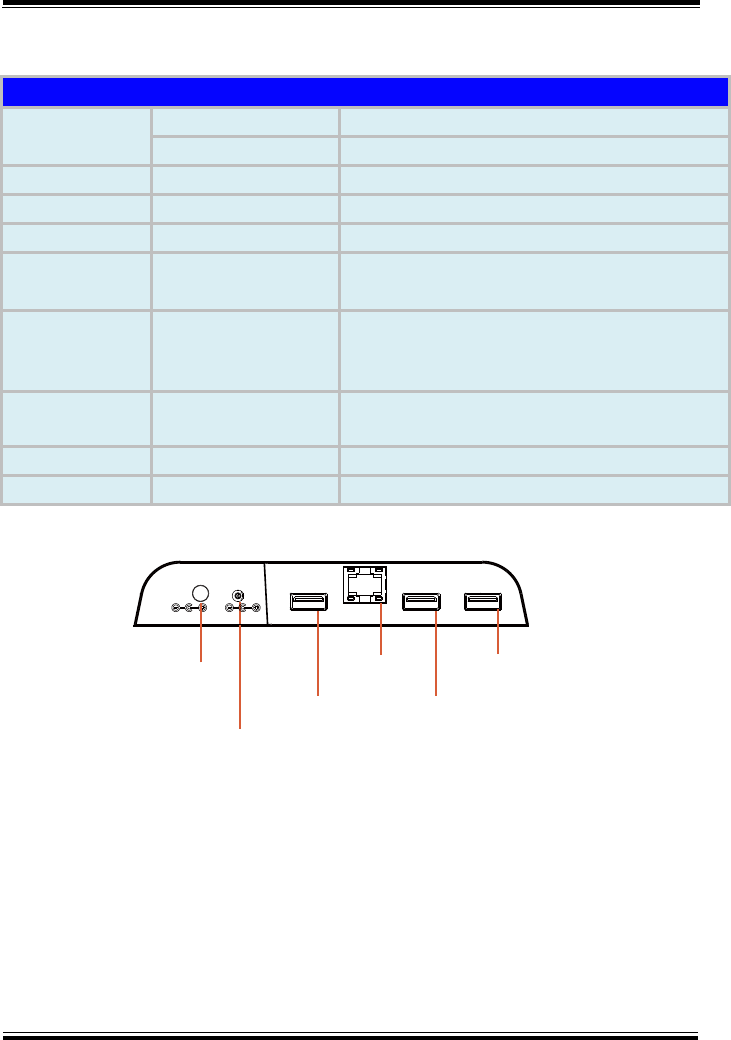
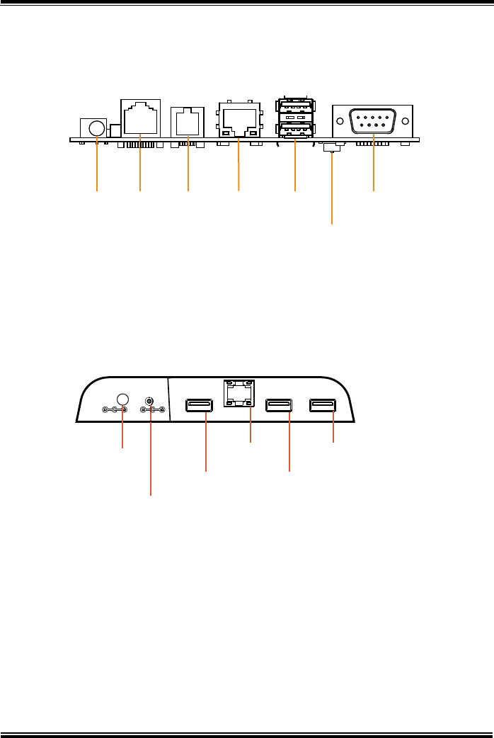
3.2 Lite Cradle / Tiltable Cradle I/O Ports Diagram
3.2.1 Lite Cradle I/O Ports Diagram
The I/O ports are located on the bottom side of the Lite Cradle.
3.2.2 Tiltable Cradle I/O Ports Diagram
The I/O ports are located on the bottom left side of Tiltable Cradle.
DC-IN RJ-45 Cash LAN 2 x D-Sub 9
Drawer USB 2.0
DIP
Switch
USB4 LAN1 USB3 USB2DC-IN 12V DC-OUT
USB2
USB3
LAN1
USB4
DC-IN
12V
DC-OUT
Chapter 3 Hardware Configuration
MH-5100 SERIES USER MANUAL
Page: 3-5
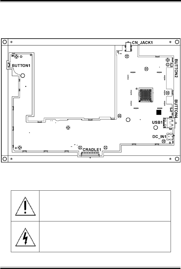
3.3 Pad Main Board Component Locations
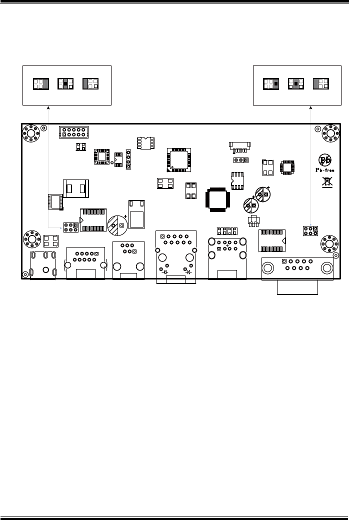
3.3.1 Top View of Pad Main Board Component Locations
M/B: MB-5100
Figure 3-1. MB-5100 Main Board Component Locations (Top View)
WARNING: Always disconnect the power cord when you are
working with the connectors on the main board. Make sure
both the system and the external devices are turned OFF as
sudden surge of power could ruin sensitive components.
Make sure MH-5100 is properly grounded.
CAUTION: Observe precautions while handling electrostatic
sensitive components. Make sure to ground yourself to
prevent static charge while configuring the connectors. Use a
grounding wrist strap and place all electronic components in
any static-shielded devices.
Chapter 3 Hardware Configuration
MH-5100 SERIES USER MANUAL
Page: 3-6
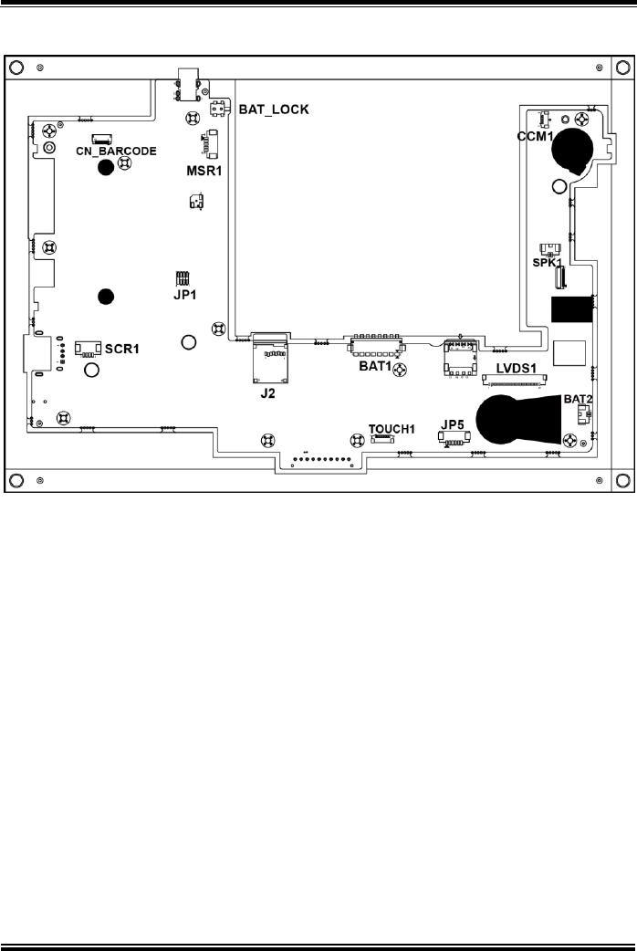
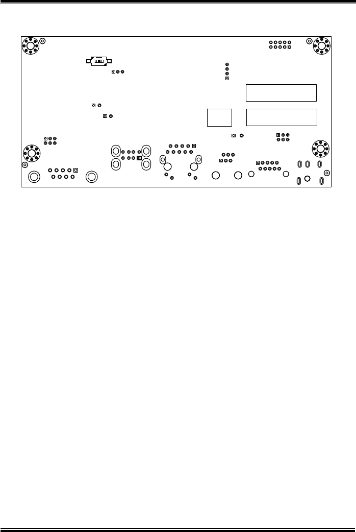
3.3.2 Bottom View of Pad Main Board Component Locations
Figure 3-2. MB-5100 Main Board Component Locations (Bottom View)

Chapter 3 Hardware Configuration
MH-5100 SERIES USER MANUAL
Page: 3-7
3.4 Pad Main Board Connectors Quick Reference
Table
CONNECTOR Description
NAME
Touch Screen Connector
TOUCH1
Flash Descriptor Override Selection
(not used after MP)
JP1
LVDS Connector
LVDS1
RTC Battery Connector
BAT2
Earphone Jack Connector
CN_JACK1
Speaker Connector
SPK1
Barcode Connector
CN_BARCODE
Left Scan Button
BUTTON1
Right Scan Button
BUTTON2
Power Button
BUTTON4
Battery Connector
BAT1
DC IN Jack Connector
DC_IN1
Cradle Connector
CRADLE1
MCU F/W Update Connector
JP5
Battery Lock Switch Button
BAT_LOCK
MicroSD Card Connector
J2
CCD Front Camera Connector
CCM1
Universal Serial Bus 2.0 Connector
USB1
MSR Connector
MSR1
SCR Connector
SCR1
Chapter 3 Hardware Configuration
MH-5100 SERIES USER MANUAL
Page: 3-8
3.5 Setting Pad Main Board Connectors
3.5.1 Touch Panel Connector (TOUCH1)
Connector Location: TOUCH1 (rear side of mainboard)
Description: Touch Panel Connector
PIN
ASSIGNMENT
1
V3P3S_TCH
2
GND
3
GND
4
I2C2_Touch_SCL
5
I2C2_Touch_SDA
6
GND
7
TOUCH_INT_R
8
TOUCH_RST_R
3.5.2 Flash Descriptor Override Selection (JP1)
Connector Location: JP1 (rear side of mainboard)
Description: Flash BIOS Connector
PIN
ASSIGNMENT
PIN
ASSIGNMENT
1
SPI_VDD
2
GND
3
SPI_CS0J_R
4
SPI_CLK_R
5
SPI_MISO_R
6
SPI_MOSI_R
7
NC
8
-
Note: The connector is not used after MP.
JP1
TOUCH1
Chapter 3 Hardware Configuration
MH-5100 SERIES USER MANUAL
Page: 3-9
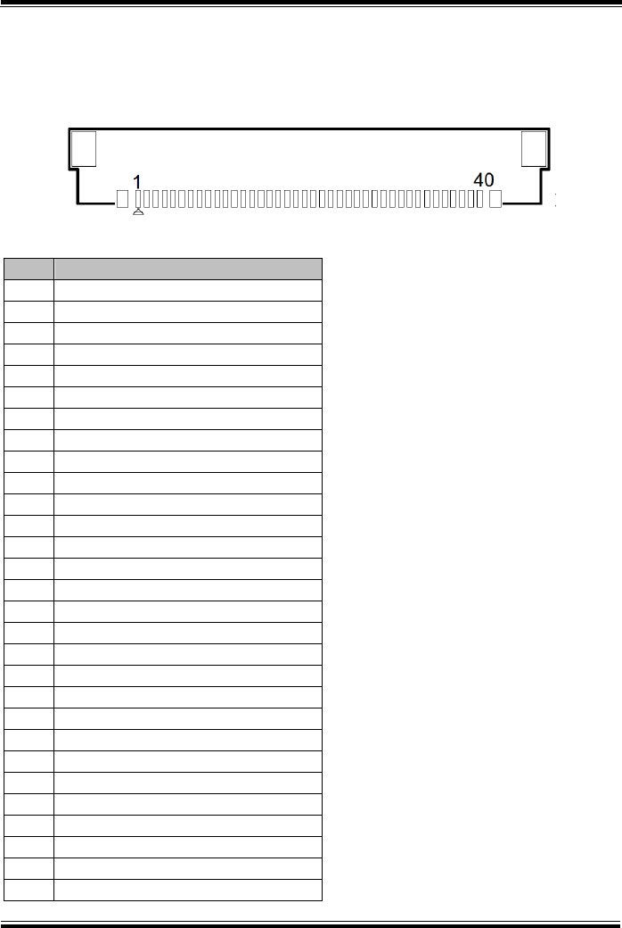
3.5.3 LVDS Connector (LVDS1)
Connector Location: LVDS1 (rear side of mainboard)
Description: LVDS (Low-Voltage Differential Signaling) Connector
PIN
ASSIGNMENT
1
NC
2
LVDS_VCC
3
LVDS_VCC
4
NC
5
NC
6
NC
7
NC
8
LVDS_A_N0
9
LVDS_A_P0
10
GND
11
LVDS_A_N1
12
LVDS_A_P1
13
GND
14
LVDS_A_N2
15
LVDS_A_P2
16
GND
17
LVDS_A_CLK_N
18
LVDS_A_CLK_P
19
GND
20
LVDS_A_N3
21
LVDS_A_P3
22
GND
23
NC
24
NC
25
GND
26
NC
27
SEL
28
GND
29
NC
LVDS1
Chapter 3 Hardware Configuration
MH-5100 SERIES USER MANUAL
Page: 3-10
PIN
ASSIGNMENT
30
NC
31
GND
32
GND
33
GND
34
NC
35
LVDS_BKLT_CTRL
36
NC
37
NC
38
VLED
39
VLED
40
VLED
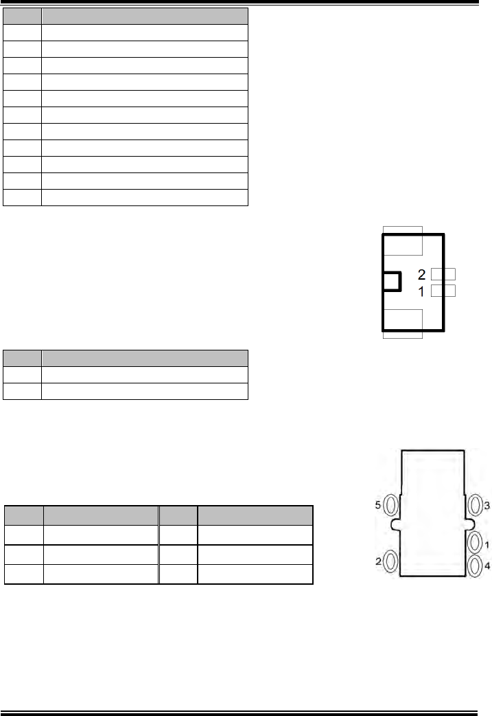
3.5.4 RTC Battery Connector (BAT2)
Connector Location: BAT2 (rear side of mainboard)
Description: RTC (Real-Time Clock) Battery Connector
The RTC battery provides power supply for the internal
real-time clock and calendar.
PIN
ASSIGNMENT
2
GND
1
VCC
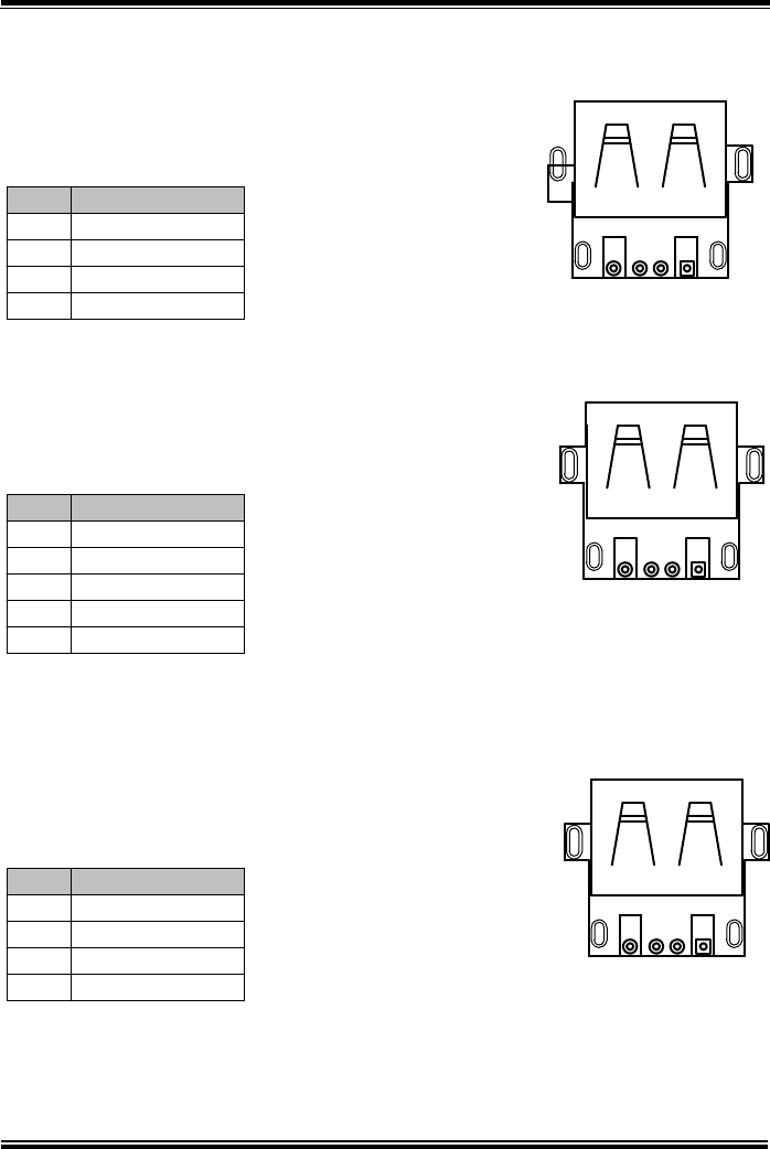
3.5.5 Earphone Jack Connector (CN_JACK1)
Connector Location: CN_JACK1 (top side of mainboard)
Description: Earphone Jack Connector
PIN
ASSIGNMENT
PIN
ASSIGNMENT
5
HP_DET
3
GND
2
RIGHT
1
LEFT
-
-
4
MIC
BAT2
CN_JACK1
Chapter 3 Hardware Configuration
MH-5100 SERIES USER MANUAL
Page: 3-11
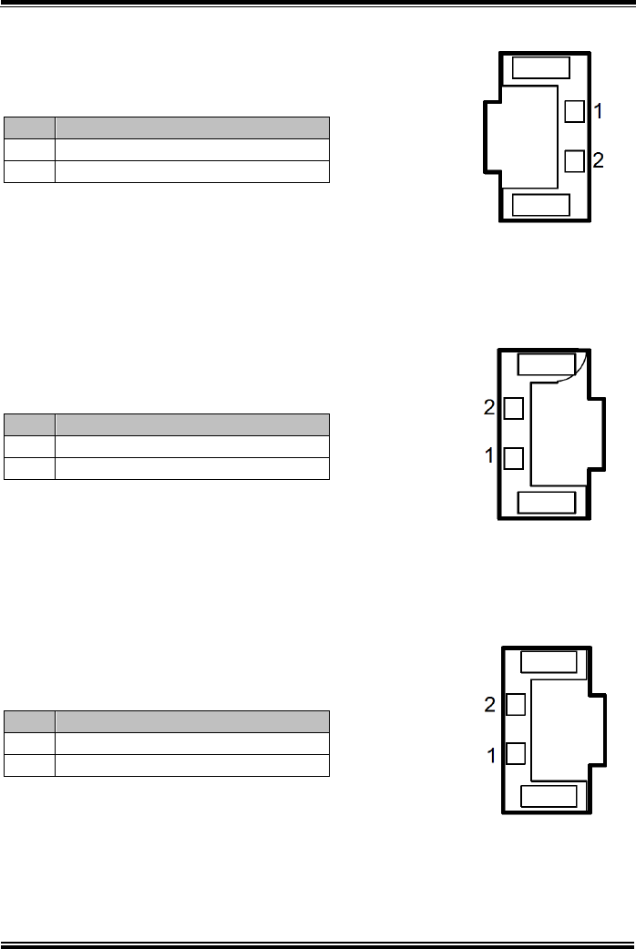
3.5.6 Speaker Connector (SPK1)
Connector Location: SPK1 (rear side of mainboard)
Description: Speaker Connector
PIN
ASSIGNMENT
PIN
ASSIGNMENT
1
LEFT_SPK
2
RIGHT_SPK
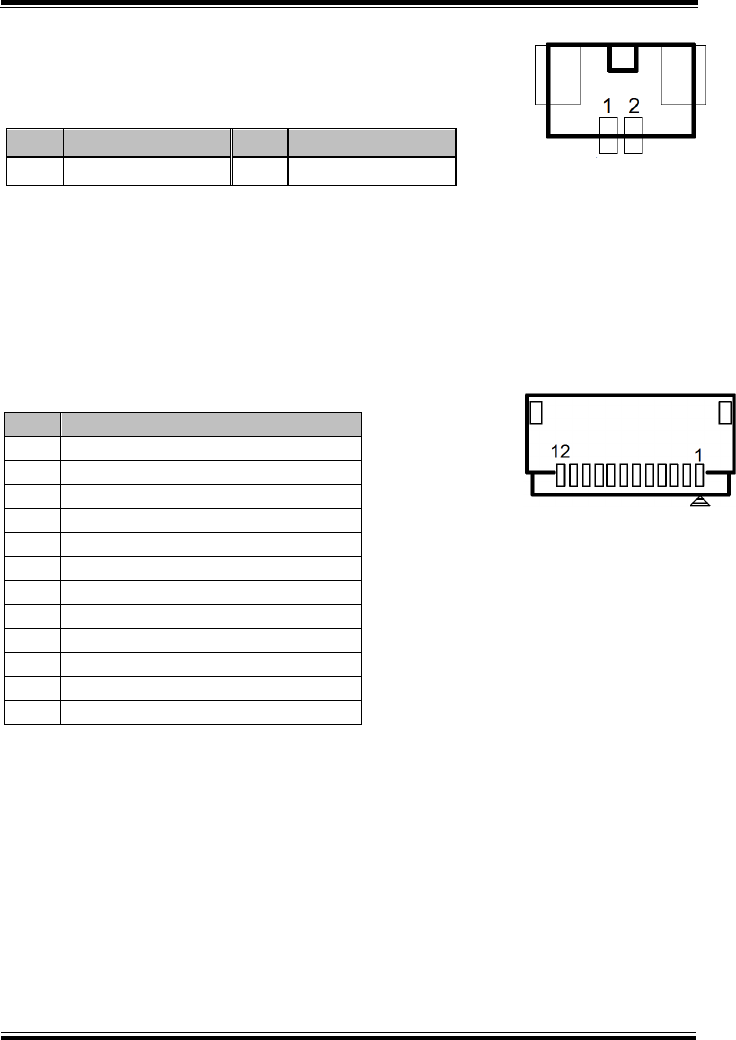
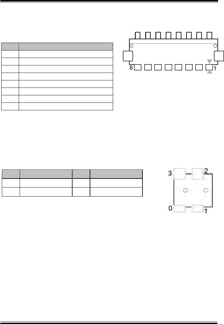
3.5.7 Barcode Scanner Connector (CN_BARCODE)
Connector Location: CN_BARCODE (rear side of mainboard)
Description: Barcode Scanner Connector
PIN
ASSIGNMENT
1
NC
2
VCC3_3
3
GND
4
RXD
5
TXD
6
CTS
7
RTS
8
Power Down
9
Buzzer
10
LED_Output
11
Wake up
12
Trigger
SPK1
CN_BARCODE
Chapter 3 Hardware Configuration
MH-5100 SERIES USER MANUAL
Page: 3-12
3.5.8 Left Scan Button (BUTTON1)
Connector Location: BUTTON1 (top side of mainboard)
Description: Left Scan Button
PIN
ASSIGNMENT
1
GND
2
SCAN_EN_SW
3.5.9 Right Scan Button (BUTTON2)
Connector Location: BUTTON2 (top side of mainboard)
Description: Right Scan Button
PIN
ASSIGNMENT
1
GND
2
SCAN_EN_SW
3.5.10 Power Button (BUTTON4)
Connector Location: BUTTON4 (top side of mainboard)
Description: Power Button
PIN
ASSIGNMENT
2
PWRBTN_N
1
GND
BUTTON1
BUTTON2
BUTTON4
Chapter 3 Hardware Configuration
MH-5100 SERIES USER MANUAL
Page: 3-13
3.5.11 Battery Connector (BAT1)
Connector Location: BAT1 (rear side of mainboard)
Description: Battery Connector
PIN
ASSIGNMENT
1
BT+
2
BT+
3
BAT1_SENSE
4
BAT_DET
5
GND
6
BAT_SCL
7
BAT_SDA
8
GND
3.5.12 DC IN Jack Connector (DC_IN1)
Connector Location: DC_IN1 (top side of mainboard)
Description: DC IN Jack Connector
PIN
ASSIGNMENT
PIN
ASSIGNMENT
3
GND
2
GND
0
DC
1
DC
BAT1
DC_IN1
Chapter 3 Hardware Configuration
MH-5100 SERIES USER MANUAL
Page: 3-14
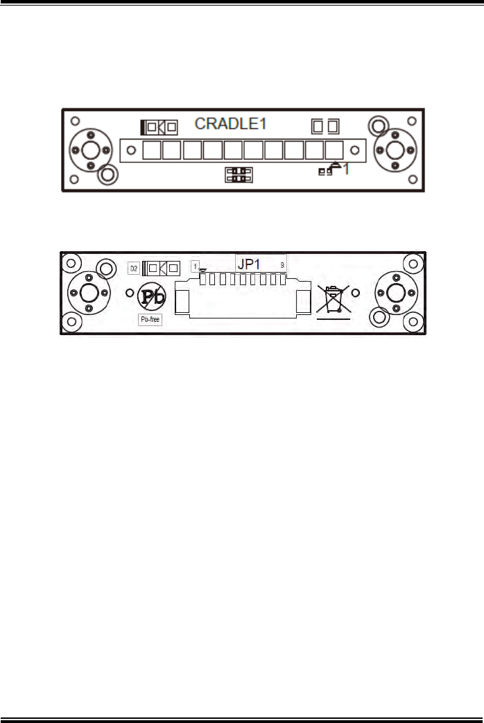
3.5.13 Cradle Connector (CRADLE1)
Connector Location: CRADLE1 (top side of mainboard)
Description: Cradle Connector
PIN
ASSIGNMENT
1
GND
2
CRA_DCIN
3
CRA_DCIN
4
GND
5
USB_DP
6
USB_DP
7
USB_DN
8
USB_DN
9
V5P0S
10
GND
3.5.14 MCU F/W Update Connector (JP5)
Connector Location: JP5 (rear side of mainboard)
Description: MCU Firmware Update Connector
PIN
ASSIGNMENT
1
MCU_MISO
2
MCU_ADC
3
MCU_SCK
4
MCU_MOSI
5
MCU_RST
6
GND
CRADLE1
JP5
Chapter 3 Hardware Configuration
MH-5100 SERIES USER MANUAL
Page: 3-15
3.5.15 Battery Lock Switch Button (BAT_LOCK)
Connector Location: BAT_LOCK (rear side of mainboard)
Description: Battery Lock Switch Button
PIN
ASSIGNMENT
PIN
ASSIGNMENT
3
NC
1
GND
4
NC
2
BAT_LOCK
3.5.16 MicroSD Card Connector (J2)
Connector Location: J2 (rear side of mainboard)
Description: MicroSD (Secure Digital) Card Connector
PIN
ASSIGNMENT
1
DAT2
2
CD/DAT3
3
CMD
4
VDD
5
CLK
6
GND
7
DATA0
8
DAT1
9
CARD DETECT
10
GND
BAT_LOCK
J2
Chapter 3 Hardware Configuration
MH-5100 SERIES USER MANUAL
Page: 3-16
3.5.17 CCD Front Camera Connector (CCM1)
Connector Location: CCM1 (rear side of mainboard)
Description: CCD (Charge-coupled Device) Front
Camera Connector
PIN
ASSIGNMENT
5
GND
4
GND
3
CCM_DP
2
CCM_DN
1
VCAM
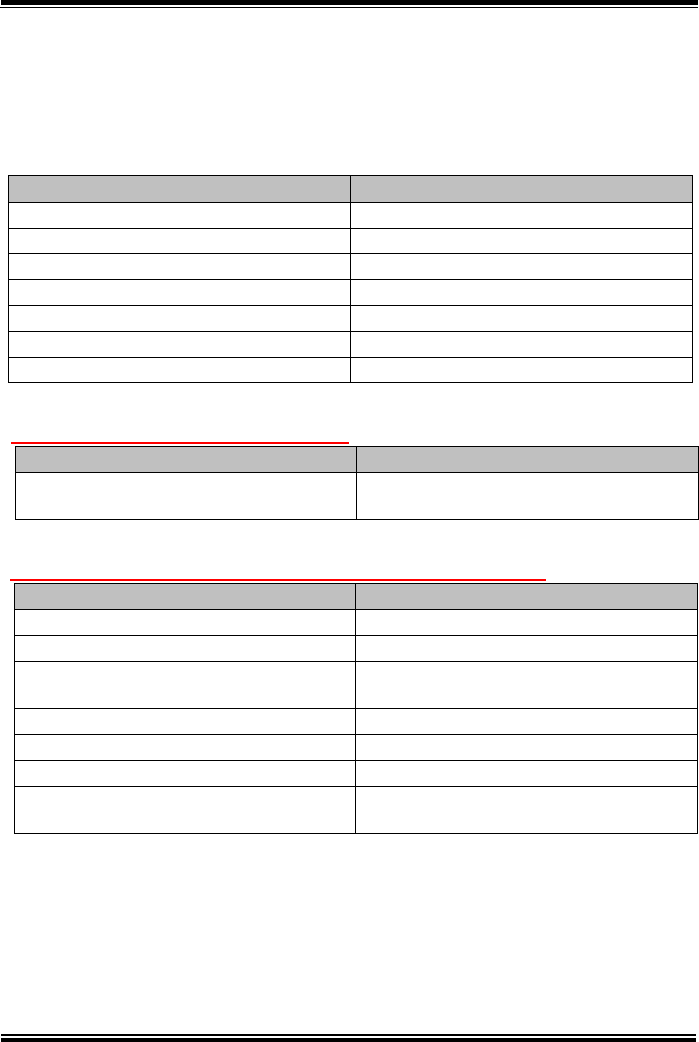
3.5.18 USB 2.0 Connector (USB1)
Connector Location: USB1 (top side of mainboard)
Description: USB 2.0 Connector
PIN
ASSIGNMENT
4
GND
3
USB_DP
2
USB_DN
1
VCC
CCM1
USB1
1
4
Chapter 3 Hardware Configuration
MH-5100 SERIES USER MANUAL
Page: 3-17
3.5.19 MSR Connector (MSR1)
Connector Location: MSR1 (rear side of mainboard)
Description: MSR (Magnetic-Stripe Card Reader)
Connector
PIN
ASSIGNMENT
1
VCC
2
MSR_DN
3
MSR_DP
4
GND
5
GND
3.5.20 SCR Connector (SCR1)
Connector Location: SCR1 (rear side of mainboard)
Description: SCR Connector
PIN
ASSIGNMENT
1
VCC
2
SCR_DN
3
SCR_DP
4
GND
MSR1
SCR1
Chapter 3 Hardware Configuration
MH-5100 SERIES USER MANUAL
Page: 3-18
3.6 Daughter Board Connectors & Jumpers Quick
Reference Table
MR-5100RA-1 Connectors List (for Tiltable Cradle)
CONNECTOR Description
NAME
DC IN Jack Connector
DC_IN1
DC OUT Jack Connector
DC_OUT
Universal Serial Bus 2.0 Connector
USB1
Universal Serial Bus 2.0 Connector
USB2
Universal Serial Bus 2.0 Connector
USB3
Universal Serial Bus 2.0 Connector
USB4
Local Area Network Connector
LAN1
MR-5100RA-5 Connectors List (For Lite Cradle)
CONNECTOR Description NAME
COM Port Connector (RJ45) COM1
COM Port Connector (D-Sub 9) COM2
Universal Serial Bus 2.0 Connector
(Dual Layers) USB1
Cash Drawer Connector DRW1
Local Area Network Connector LAN1
DC IN Jack Connector DC_IN1
LAN & Cash Drawer Function
Switch (MR-5100RA-5 Bottom Side) SW1
MR-5100RA-2 Connector List (for Lite Cradle)
CONNECTOR Description NAME
Lite Cradle Connector /
Tiltable Cradle Connector CRADLE1
Chapter 3 Hardware Configuration
MH-5100 SERIES USER MANUAL
Page: 3-19
MR-5100RA-5 Jumpers List (For Lite Cradle)
JUMPER Description
NAME
COM1 Port Pin9 Definition Selection
Guide (MR-5100RA-5)
JP_COM1
COM2 Port Pin9 Definition Selection
Guide (MR-5100RA-5)
JP_COM2
MR-5100RA-3 Connectors List (for External Barcode
Scanner (optional))
CONNECTOR Description
NAME
Barcode Scanner Connector
CN_BARCODE1
Barcode Scanner Connector
CN_BARCODE2
Trigger Connector
JP1
Trigger Connector
JP2
MR-5100RA-8 Connectors List (for Scan Button)
CONNECTOR Description
NAME
Barcode Scanner Function Switch
Connector
SW1
Trigger Connector
JP1
Trigger Connector
JP2
Chapter 3 Hardware Configuration
MH-5100 SERIES USER MANUAL
Page: 3-20
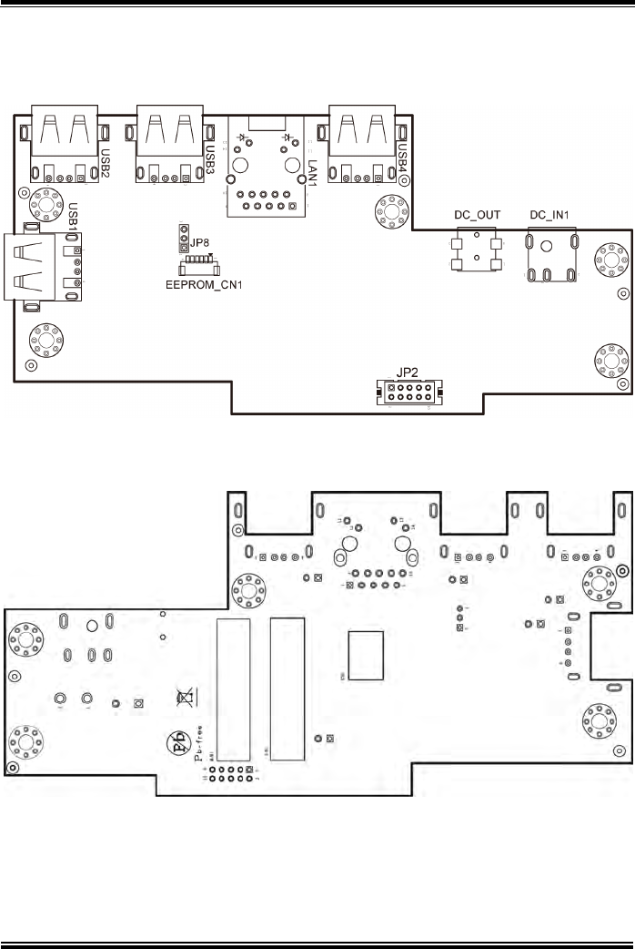
3.7 Daughter Board MR-5100RA-1 Connectors
Location
Figure 3-3. MR-5100RA-1 Daughter Board Component Locations (Top View)
Figure 3-4. MR-5100RA-1 Daughter Board Component Locations (Bottom View)
Chapter 3 Hardware Configuration
MH-5100 SERIES USER MANUAL
Page: 3-21
3.8 Setting Daughter Board MR-5100RA-1
Connectors
3.8.1 DC IN Jack Connector (DC_IN1)
Connector Location: DC_IN1
Description: DC IN Jack Connector. The DC_IN1 port
is located on the bottom left side of Tiltable Cradle.
PIN
ASSIGNMENT
0
VCC12V
1
GND
3.8.2 DC Out Jack Connector (DC_OUT)
Connector Location: DC_OUT
Description: DC Out Jack Connector. The DC_OUT port
is located on the bottom left side of Tiltable Cradle.
PIN
ASSIGNMENT
0
VCC8.4V
1
GND
3.8.3 Universal Serial Bus 2.0 Connector (USB1)
Connector Location: USB1
Description: USB 2.0 Connector. The USB1 port
is located on the bottom front of Tiltable Cradle.
PIN
ASSIGNMENT
1
VCC5V
2
D-
3
D+
4
GND
DC_IN1
DC_OUT
USB1
1
4
Chapter 3 Hardware Configuration
MH-5100 SERIES USER MANUAL
Page: 3-22
3.8.4 Universal Serial Bus 2.0 Connector (USB2)
Connector Location: USB2
Description: USB 2.0 Connector. The USB2 port
is located on the bottom left side of Tiltable Cradle.
PIN
ASSIGNMENT
1
VCC5V
2
D-
3
D+
4
GND
3.8.5 Universal Serial Bus 2.0 Connector (USB3)
Connector Location: USB3
Description: USB 2.0 Connector. The USB3 port
is located on the bottom left side of Tiltable Cradle.
PIN
ASSIGNMENT
1
VCC5V
2
D-
3
D+
4
GND
5
Shield
3.8.6 Universal Serial Bus 2.0 Connector (USB4)
Connector Location: USB4
Description: USB 2.0 Connector. The USB4 port
is located on the bottom left side of Tiltable Cradle.
PIN
ASSIGNMENT
1
VCC5V
2
D-
3
D+
4
GND
USB2
41
USB3
41
USB4
41
Chapter 3 Hardware Configuration
MH-5100 SERIES USER MANUAL
Page: 3-23
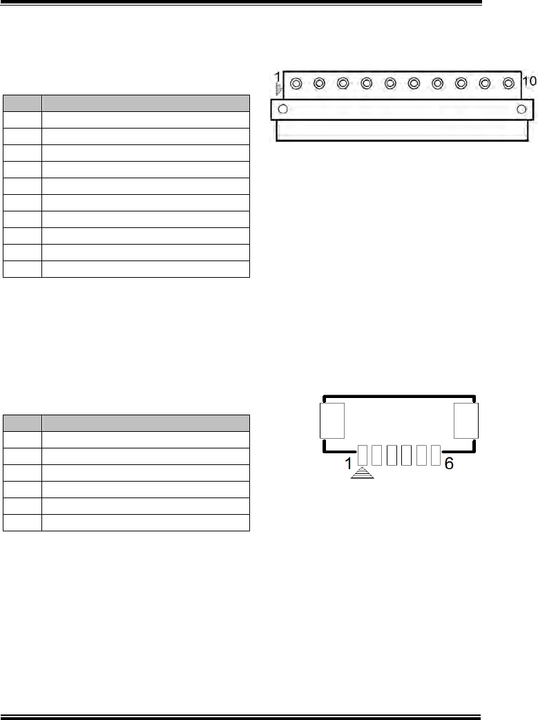
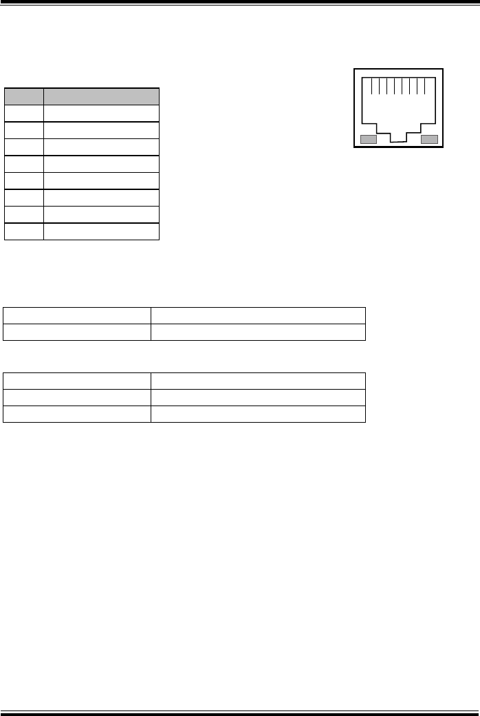
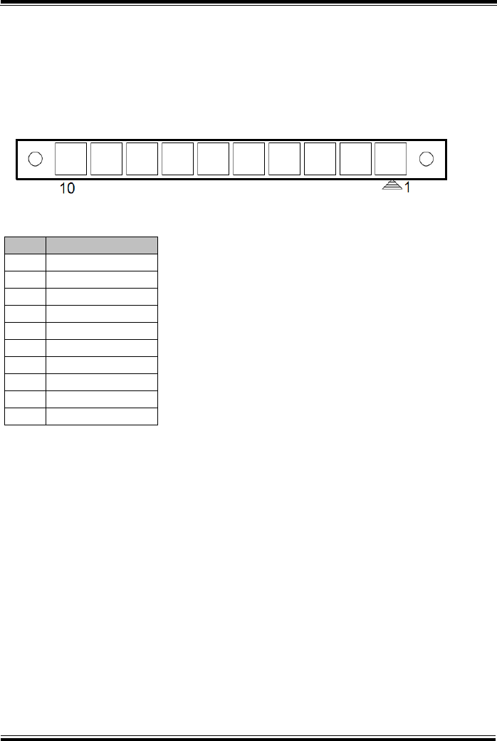
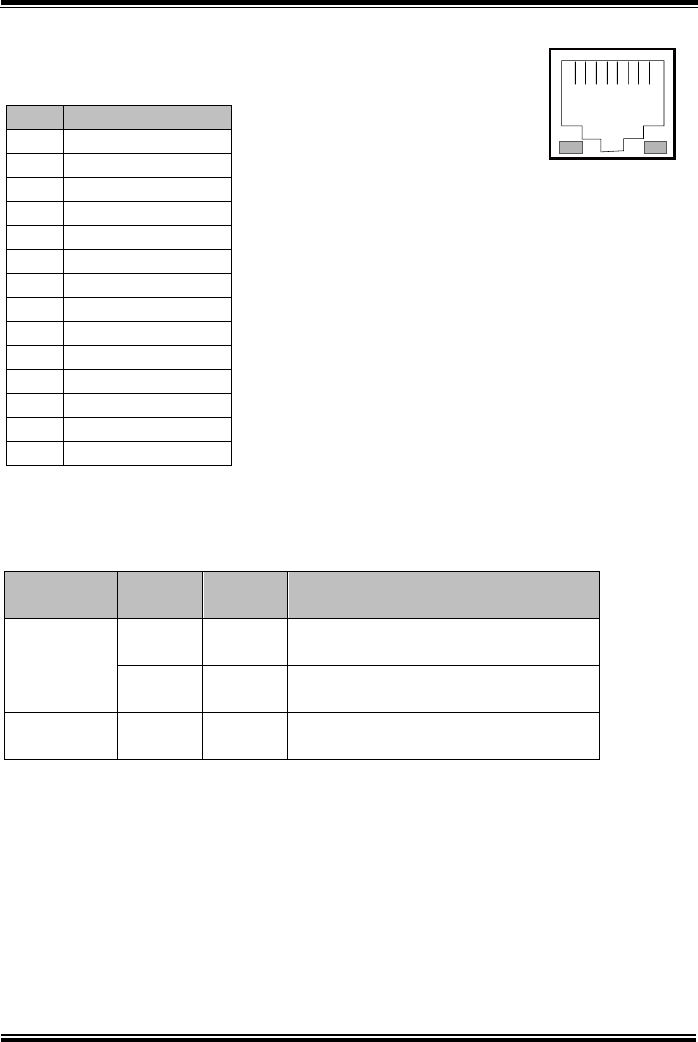
3.8.7 LAN Port (LAN1)
Port Name: LAN1
Description: LAN RJ-45 Port (bottom left I/O)
PIN
ASSIGNMENT
1
MDIP0
2
MDIN0
3
MDIP1
4
MDIN1
5
MDIP2
6
MDIN2
7
MDIP3
8
MDIN3
LAN LED Indicator:
Right Side LED
Yellow Color Blinking
LAN Message Active
Off
No LAN Message Active
Left Side LED
Green Color On
10/100Mbps LAN Speed Indicator
Orange Color on
Giga LAN Speed Indicator
Off
No LAN switch/ hub connected.
81
Green Yellow
LAN1
Chapter 3 Hardware Configuration
MH-5100 SERIES USER MANUAL
Page: 3-24
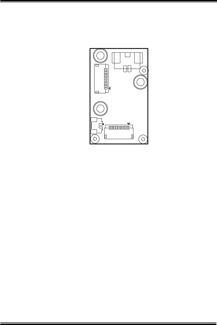
3.9 Daughter Board MR-5100RA-2 Connectors
Location
Figure 3-5. MR-5100RA-2 Daughter Board Component Locations (Top View)
Figure 3-6. MR-5100RA-2 Daughter Board Component Locations (Bottom View)
Chapter 3 Hardware Configuration
MH-5100 SERIES USER MANUAL
Page: 3-25
3.10 Setting Daughter Board MR-5100RA-2
Connector
3.10.1 Lite Cradle / Tiltable Cradle Connector (CRADLE1)
Connector Location: CRADLE1
Description: Lite Cradle / Tiltable Cradle Connector
PIN
ASSIGNMENT
1
GND
2
CRA_DCIN
3
CRA_DCIN
4
GND
5
USB_DP
6
USB_DP
7
USB_DN
8
USB_DN
9
V5P0S
10
GND
CRADLE1
Chapter 3 Hardware Configuration
MH-5100 SERIES USER MANUAL
Page: 3-26
3.11 Daughter Board MR-5100RA-3 Connectors
Location
Figure 3-7. MR-5100RA-3 Daughter Board Component Locations (Top View)
CNB_BARCODE2
CNB_BARCODE1
JP2
JP1
Chapter 3 Hardware Configuration
MH-5100 SERIES USER MANUAL
Page: 3-27
3.12 Setting Daughter Board MR-5100RA-3
Connectors
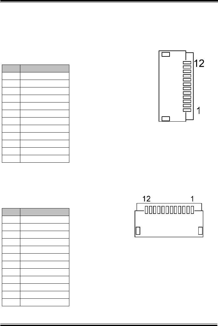
3.12.1 Barcode Scanner Connector (CN_BARCODE1)
Connector Location: CN_BARCODE1
Description: Barcode Scanner Connector
PIN
ASSIGNMENT
1
NC
2
VCC3_3
3
GND
4
RXD
5
TXD
6
CTS
7
RTS
8
Power Down
9
Buzzer
10
LED_Output
11
Wake up
12
Trigger
3.12.2 Bar Code Scanner Connector (CN_BARCODE2)
Connector Location: CN_BARCODE2
Description: Barcode Scanner Connector
PIN
ASSIGNMENT
1
NC
2
VCC3_3
3
GND
4
RXD
5
TXD
6
CTS
7
RTS
8
Power Down
9
Buzzer
10
LED_Output
11
Wake up
12
Trigger
CN_BARCODE1
CN_BARCODE2
Chapter 3 Hardware Configuration
MH-5100 SERIES USER MANUAL
Page: 3-28
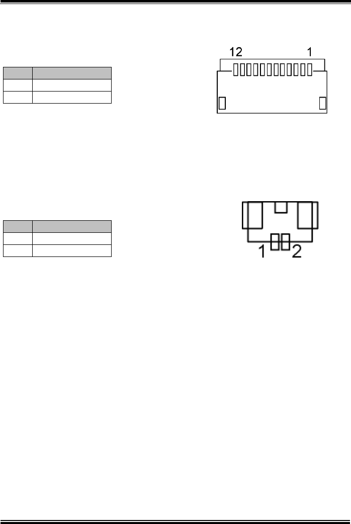
3.12.3 Trigger Connector (JP1)
Connector Location: JP1
Description: Trigger Connector
PIN
ASSIGNMENT
1
Trigger
2
GND
3.12.4 Trigger Connector (JP2)
Connector Location: JP2
Description: Trigger Connector
PIN
ASSIGNMENT
1
Trigger
2
GND
JP1
JP2
Chapter 3 Hardware Configuration
MH-5100 SERIES USER MANUAL
Page: 3-29
3.13 Daughter Board MR-5100RA-5 Connectors &
Jumpers Location
Note: When the Lite Cradle is joined with Integrated Pad, the COM2 and COM3 ports
shown on Pad system are actually COM1 and COM2 ports of the daughter
board respectively, because the Lite Cradle’s COM ports are deployed
according to OS Image built by Protech and COM1 port placement has been
used by Pad system.
JP_COM1 Pin9 RI/5V/12V JP_COM2 Pin9 RI/5V/12V
5 5
6 6
RI
12V 5V
RI
12V 5V
(default) (default)
6 10
1 5 U8
JP1 EEPROM_CN1
10 24
ESD4 6
U12 JP3
U1
15
U13 48 Y1
1U6
8
L5 3
4U17
2CP6
164 1
48
Q36
U16
CP5
U9 28 15 GL2
U5
JP_COM1
Q1
51
2
3
621 14 51
U7 62
1
4
1
4
958
JP_COM2
210
14
91
10 2
12
11 14
13
(RJ-45)
(D-Sub 9)
1
2
2
1
2
22
5
6
1
2
43
2
1
5
6
32
116
8
1
25
1
2
9
2
1
2
5
6
1
2
5
6
96
5 1
28
15
14
1
IO
21 15
14
28 8
171 3
6 1
DC_IN1
2
4 3
322 12
1
COM1
12111
43
1 2
DRW1
14
JP2
LAN1
36
Y3 3
412
2
1
USB1
ESD3
3
1 2
ESD5
COM2
Chapter 3 Hardware Configuration
MH-5100 SERIES USER MANUAL
Page: 3-30
Figure 3-8. MR-5100RA-5 Daughter Board Component Locations (Bottom View)
10 6
5 1
LAN DWR
14
13
SW1
1
M/N:
ECN: S/N:
15
1526
26
91
8 5
10 2
41
19
2 10
14 12
13 11
ON
Chapter 3 Hardware Configuration
MH-5100 SERIES USER MANUAL
Page: 3-31
3.14 Setting Daughter Board MR-5100RA-5
Connectors and Jumpers
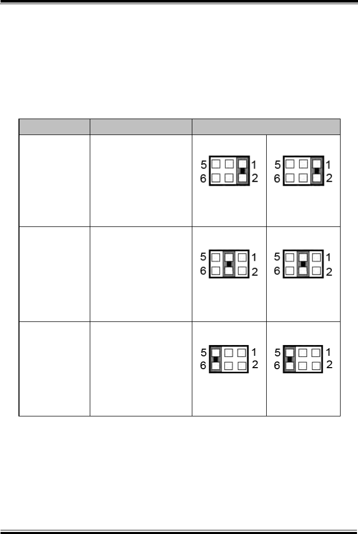
3.14.1 COM1, COM2 Port Pin9 Definition Selection Guide
(JP_COM1 and JP_COM2)
Jumper Location: JP_COM1 and JP_COM2
Description: COM1, COM2 Port Pin9 RI/+5V/+12V Selection
SELECTION
JUMPER SETTING
JUMPER ILLUSTRATION
RI
1-2
(Default Setting)
JP_COM1
JP_COM2
12V
3-4
JP_COM1
JP_COM2
5V
5-6
JP_COM1
JP_COM2
Chapter 3 Hardware Configuration
MH-5100 SERIES USER MANUAL
Page: 3-32
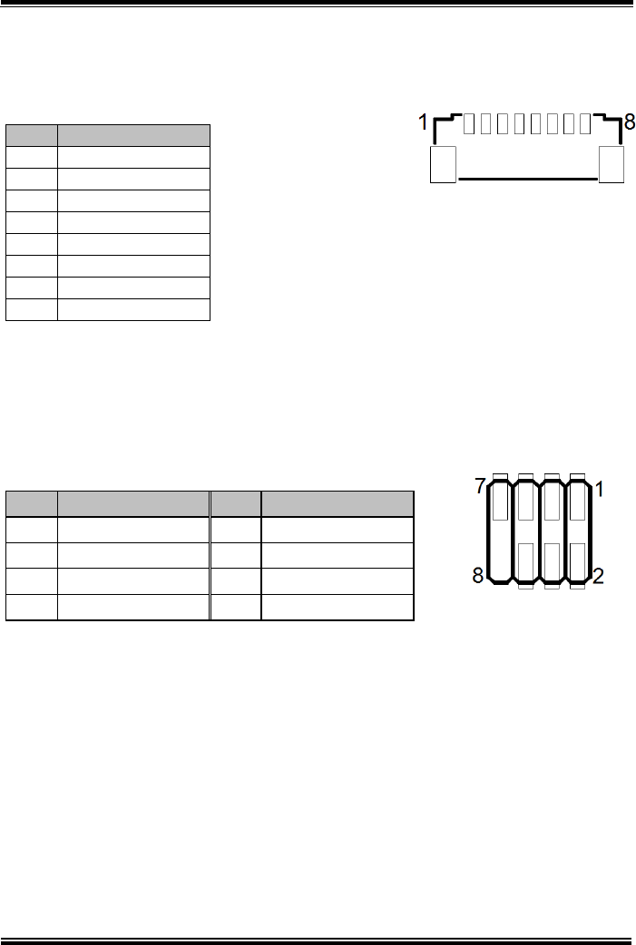
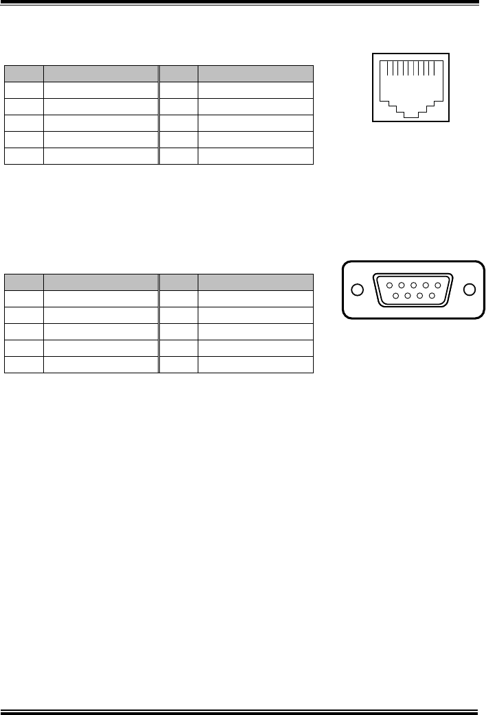
3.14.2 RJ-45 COM Port (COM1)
COM1(RS-232, RJ-45) Connector Pin Assignment
PIN
ASSIGNMENT
PIN
ASSIGNMENT
1
DCD
6
DSR
2
RXD
7
RTS
3
TXD
8
CTS
4
DTR
9
RI/5V/12V
5
GND
-
Note: COM1 Pin 9 is selectable for RI, +5V or +12V by jumper setting. Default setting is RI.
Please see “COM1, COM2 Port Pin9 Definition Selection Guide” section for
selection details.
3.14.3 D-Sub 9 COM Port (COM2)
COM2(RS-232, D-Sub 9) Connector Pin Assignment:
PIN
ASSIGNMENT
PIN
ASSIGNMENT
1
DCD
6
DSR
2
RXD
7
RTS
3
TXD
8
CTS
4
DTR
9
RI/5V/12V
5
GND
-
Note: COM2 Pin 9 is selectable for RI, +5V or +12V by jumper setting. Default setting is RI.
Please see “COM1, COM2 Port Pin9 Definition Selection Guide” section for
selection details.
5
1
9
6
COM2
101
COM1
Chapter 3 Hardware Configuration
MH-5100 SERIES USER MANUAL
Page: 3-33
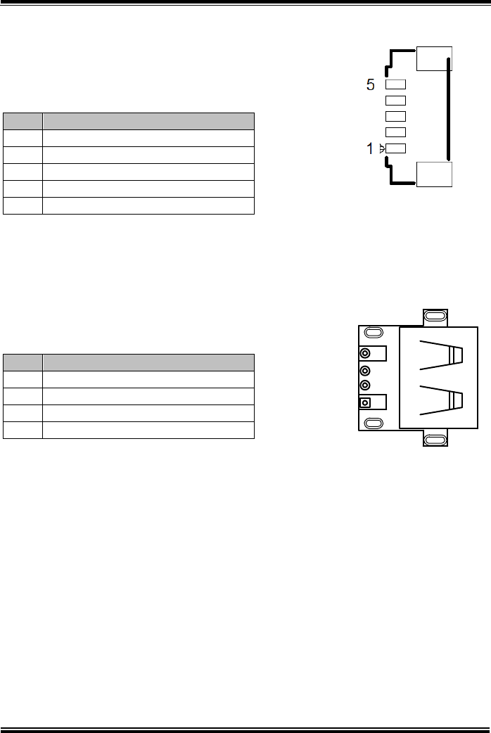
3.14.4 DC-IN Port (DC_IN1)
Port Name: DC_IN1
Description: DC Power-In Port. The DC-IN Port is located
on the bottom side of Lite Cradle.
PIN
ASSIGNMENT
1
VCC12V
2
GND
3
GND
3.14.5 Dual USB Ports
Port Name: USB1
Description: Dual USB 2.0 Type A Connectors
PIN
ASSIGNMENT
PIN
ASSIGNMENT
1
VCC5V
5
VCC5V
2
USB_DN
6
USB_DN
3
USB_DP
7
USB_DP
4
GND
8
GND
Note: The top USB 2.0 connector pin assignments are the
same as the one below.
USB1
DC_IN1
Chapter 3 Hardware Configuration
MH-5100 SERIES USER MANUAL
Page: 3-34
3.14.6 Local Area Network (LAN) Port (LAN1)
Port Name: LAN1
Description: a Giga LAN RJ-45 Port
PIN
ASSIGNMENT
1
MX0+
2
MX0-
3
MX1+
4
MX1-
5
CT1
6
CT2
7
NC
8
NC
9
NC
10
NC
11
SPEED_LED
12
VCC3.3V
13
LINK_ACT_LED
14
VCC3.3V
LAN LED Status
There are 2 LAN LED indicators for LAN on the bottom side of the Lite Cradle. By
observing their status, you can know the status of the Ethernet connection.
LAN LED
Indicator
Color
Status
Description
Left Side
LED
Orange
Blink
Giga LAN connection is activated.
Green
Blink
10/100Mbps LAN connection is
activated.
Right Side
LED
Green
On
LAN switch/hub connected.
18
Green/Orange
Yellow
LAN1
Chapter 3 Hardware Configuration
MH-5100 SERIES USER MANUAL
Page: 3-35
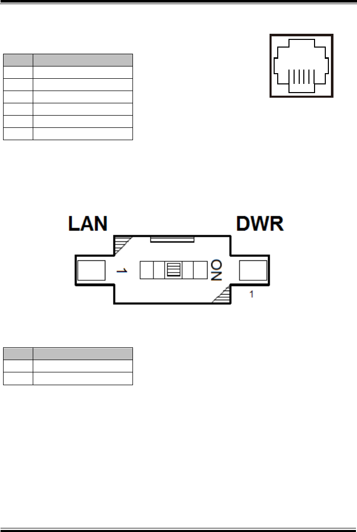
3.14.7 Cash Drawer Port (DRW1)
Port Name: DRW1
Description: RJ-11 Cash Drawer Port
PIN
ASSIGNMENT
1
GND
2
DRAWER_OPEN
3
DRAWER_SENSE
4
VCC12V
5
NC
6
GND
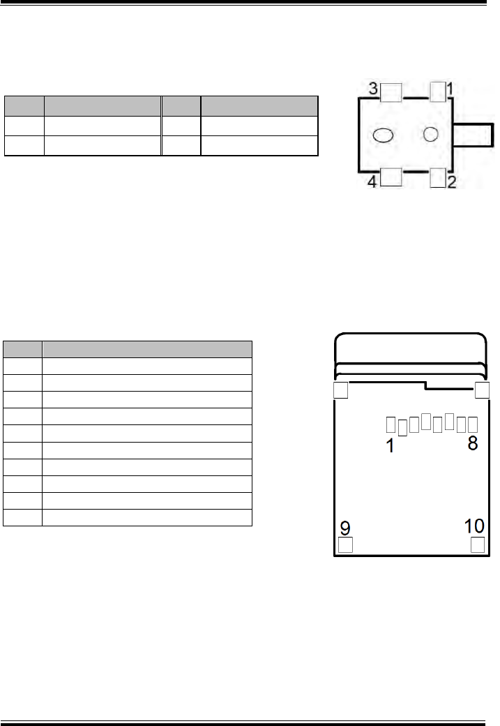
3.14.8 LAN & Cash Drawer Function Switch (SW1)
Connector Name: SW1
Description: LAN Port and Cash Drawer function selection
PIN
ASSIGNMENT
1
CASH DRAWER
2
LAN
Note: Users need to use a ball point pen or a pin to toggle the DIP switch.
Default: LAN
16
DRW1
SW1
Chapter 3 Hardware Configuration
MH-5100 SERIES USER MANUAL
Page: 3-36
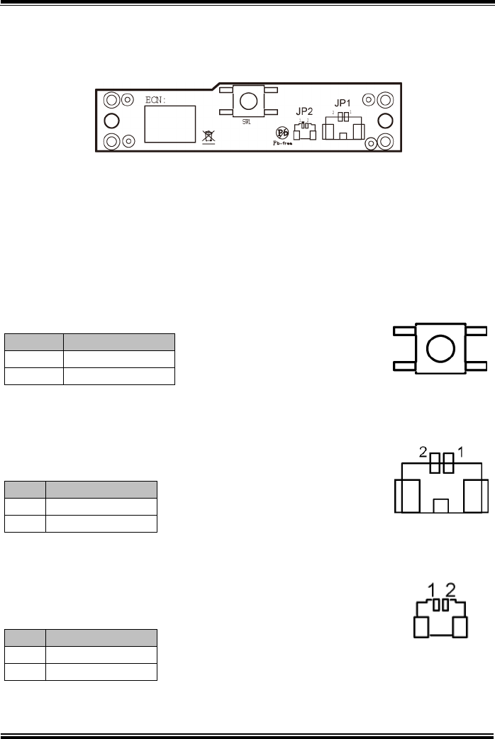
3.15 Daughter Board MR-5100RA-8 Connectors
Location
Figure 3-9. MR-5100RA-8 Daughter Board Component Locations (Top View)
3.16 Setting Daughter Board MR-5100RA-8
Connectors
3.16.1 Barcode Scanner Function Switch Connector (SW1)
Connector Location: SW1
Description: Barcode Scanner Function Switch Connector
PIN
ASSIGNMENT
Click
Trigger
Release
Normal
3.16.2 Trigger Connector (JP1)
Connector Location: JP1
Description: Trigger Connector
PIN
ASSIGNMENT
1
Trigger
2
GND
3.16.3 Trigger Connector (JP2)
Connector Location: JP2
Description: Trigger Connector
PIN
ASSIGNMENT
1
Trigger
2
GND
JP1
JP2
SW1

MH-5100 SERIES USER MANUAL
Page: 4-1
4 Software Utilities
This chapter provides the detailed information that guides
users to install driver utilities for the system. The following
topics are included:
• Installing Intel® Chipset Software Installation Utility
• Installing Audio Realtek Software Installation Utility
• Installing G-Sensor Software Installation Utility
• Installing Bluetooth Software Installation Utility
• Cash Drawer API Reference

Chapter 4 Software Utilities
MH-5100 SERIES USER MANUAL
Page: 4-2
4.1 Introduction
MH-5100 Driver Utilities have been stored in the Integrated Pad
system:
File Path: C:\MH-5100_v1.0
Filename
(Assume that drive is C:)
Purpose
Win10
32-bit
OS
C:\MH-5100_v1.0\DRIVER\
Platform\1_Main Chip
\Win10-32Bit
Intel® Chipset Device Software installer
(Audio & BM& DPTF & GFX & GPIO &
GPIO & I2C & MBI & PMIC & Sensor &
TXEI & UART & WCE & TXE)
C:\MH-5100_v1.0\DRIVER\
Platform\2_Audio\
Win10-32Bit
Realtek High Definition Audio System
Software
C:\MH-5100_v1.0\DRIVER\
Device\3_G-sensor\
Win10-32Bit
ST Microelectronics 3 Axis Digital
Accelerometer Installer
C:\MH-5100_v1.0\DRIVER\
Platform\4_BlueTooth\
Win10-32Bit
USI WM-BAN-BM-10_LS Bluetooth v4.0
Software
: Support
Note: After the OS installation is completed, the driver utilities will also be installed
at the same time.

Chapter 4 Software Utilities
MH-5100 SERIES USER MANUAL
Page: 4-3
4.2 Installing Intel® Chipset Software Installation
Utility
Introduction
The Intel® Chipset Software Installation Utility installs the Windows
*.INF files to the target system. These files outline to the operating
system how to configure the Intel chipset components in order to
ensure that the following functions work properly:
•Core PCI and ISAPNP Services
•PCIe Support
•SATA Storage Support
•USB Support
•Identification of Intel® Chipset Components in the Device Manager
The utility pack is to be installed only for Windows® 10 series
(32-bit). Please follow the steps below to install:
1Enter the C:\MH-5100_v1.0 > DRIVER > Platform > 1_Main
Chip > Win10-32Bit > Installer > PlatformInstaller folder
where the Chipset driver is located.
2Click Setup.exe file for driver installation.
3Follow the on-screen instructions to install the driver.
4Enter the C:\MH-5100_v1.0 > DRIVER > Platform> 1_Main
Chip > Win10-32Bit > Installer > SecInstaller folder.
5Click SetupTXE.exe file for driver installation.
6Follow the on-screen instructions to install the driver.
7Once the installation is completed, restart MH-5100 for the
changes to take effect.

Chapter 4 Software Utilities
MH-5100 SERIES USER MANUAL
Page: 4-4
After the Chipset driver is installed, the following driver utilities will
also be installed at the same time:
• Audio driver utility
• BM driver utility
• DPTF driver utility
• GFX driver utility
• GPIO driver utility
• GPIOVirtual driver utility
• I2C driver utility
• MBI driver utility
• PMIC driver utility
• Sensor driver utility
• TXEI driver utility
• UART driver utility
• WCE driver utility
For more details on the installation procedure, refer to the MH-5100
README V1.0.pdf file located under C:\MH-5100_v1.0.

Chapter 4 Software Utilities
MH-5100 SERIES USER MANUAL
Page: 4-5
4.3 Installing Audio Realtek Software Installation
Utility
After the default Audio driver utility has been installed in the
procedure above, it will not function until you have installed Realtek
ALC5640-VB-CG driver utilities. Please follow the steps below:
1 Enter the C:\MH-5100_v1.0 > DRIVER > Platform > 2_Audio
> Win10-32Bit > RTK_6_2_9600_4239_WHQL > x86 folder
where the Audio Realtek ALC5640-VB-CG driver is located, and
rtii2sac.inf file will be installed automatically.
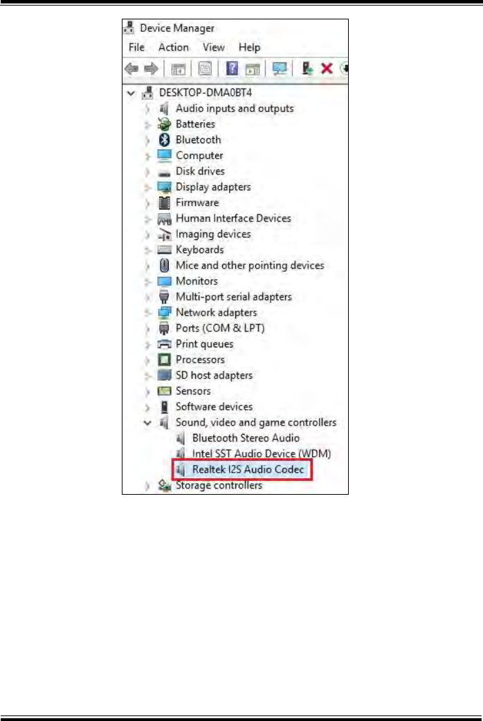
2 From the bottom left corner of MH-5100 Pad, select Start
icon > Windows System > Control Panel > Device Manager to
enter the Device Manager window, and select
DESKTOP-DMA0BT4 > Sound, video and game controllers
> Realtek I2S Audio Codec.
Chapter 4 Software Utilities
MH-5100 SERIES USER MANUAL
Page: 4-6
Chapter 4 Software Utilities
MH-5100 SERIES USER MANUAL
Page: 4-7
3 From Realtek I2S Audio Codec Properties window, click
Update Driver… from the Driver tab to start updating the audio
driver software for MH-5100.
4 Click Browse my computer for driver software item.
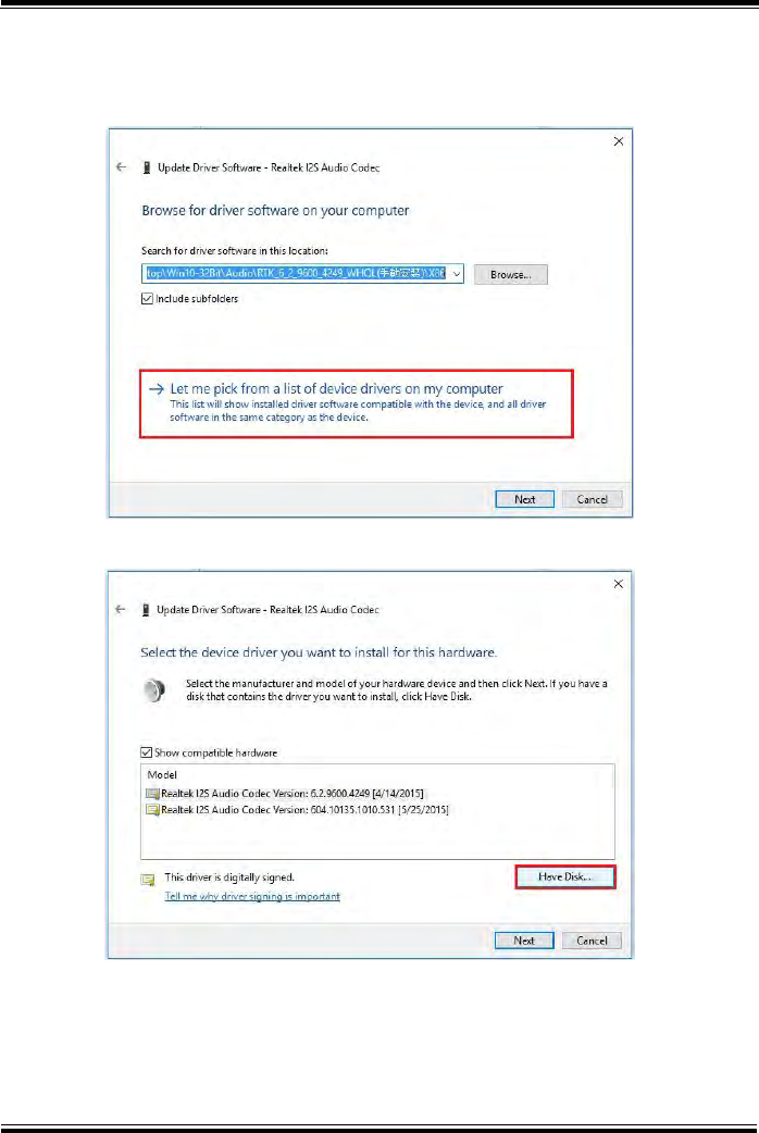
Chapter 4 Software Utilities
MH-5100 SERIES USER MANUAL
Page: 4-8
5 Click Let me pick from a list of device drivers on my
computer.
6 Click Have Disk….
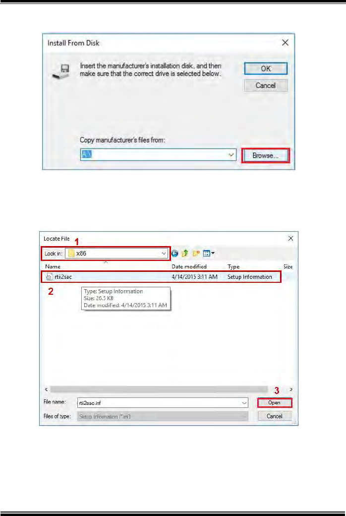
Chapter 4 Software Utilities
MH-5100 SERIES USER MANUAL
Page: 4-9
7 Click Browse... button to browse for the file directory where the
Realtek I2S Audio Codec installation driver is located.
8 Select C:\MH-5100_v1.0 > DRIVER > Platform > 2_Audio >
Win10-32Bit > RTK_6_2_9600_4239_WHQL> x86, select
rtii2sac.inf file and click Open to open the file.
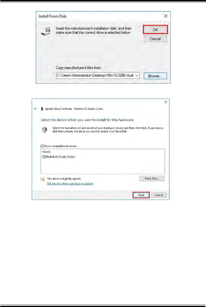
Chapter 4 Software Utilities
MH-5100 SERIES USER MANUAL
Page: 4-10
9 Click OK.
10 Click Next to continue the installation.
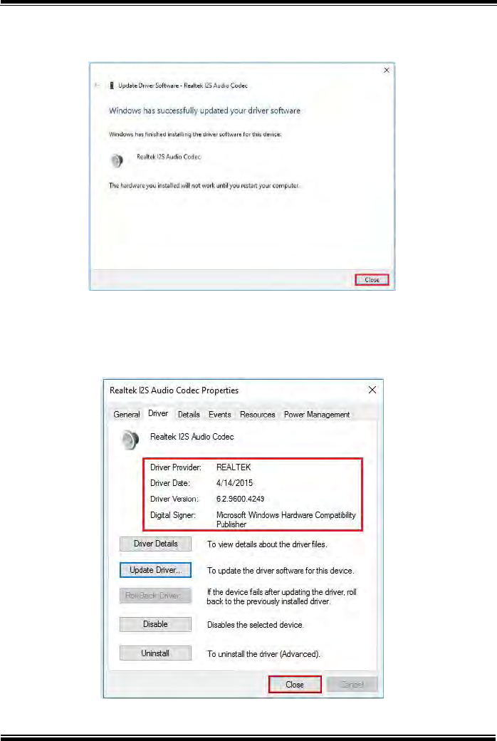
Chapter 4 Software Utilities
MH-5100 SERIES USER MANUAL
Page: 4-11
11 Windows has finished installing Realtek I2S Audio Codec driver
software. Click Close to complete.
12 Go to Realtek I2S Audio Codec Properties window and select
Driver tab, and you will see the Realtek audio driver utility has
been updated. Click Close to exit.

Chapter 4 Software Utilities
MH-5100 SERIES USER MANUAL
Page: 4-12
13 Once the installation is completed, restart MH-5100 for the
changes to take effect, and the audio function can start to work
normally.
4.4 Installing G-Sensor Software Installation
Utility
The G-Sensor driver utility provided allows users to turn the touch
screen horizontally or vertically. Please follow the steps below to
install G-Sensor driver utilities:
1 Enter the C:\MH-5100_v1.0 >DRIVER > Platform >
3_G-sensor > Win10-32Bit > 1_4.22.0063_signed(STEP-1)
folder.
2 Click setup.exe file for driver installation.
3 Follow the on-screen instructions to install the driver.
4 Enter the C:\MH-5100_v1.0 > DRIVER > Platform >
3_G-sensor > Win10-32Bit >
2_Accel_SPB_SensorAPI_2.8.1.10(STEP-2) > x86 folder, and the
ST_Accel.inf file will be installed automatically.
5 From the bottom left corner of MH-5100 Pad, select Start
icon > Windows System > Control Panel > Device Manager to
enter the Device Manager window, and select
DESKTOP-DMA0BT4 > Sensors > STMicroelectronics
3-Axis Digital Accelerometer.
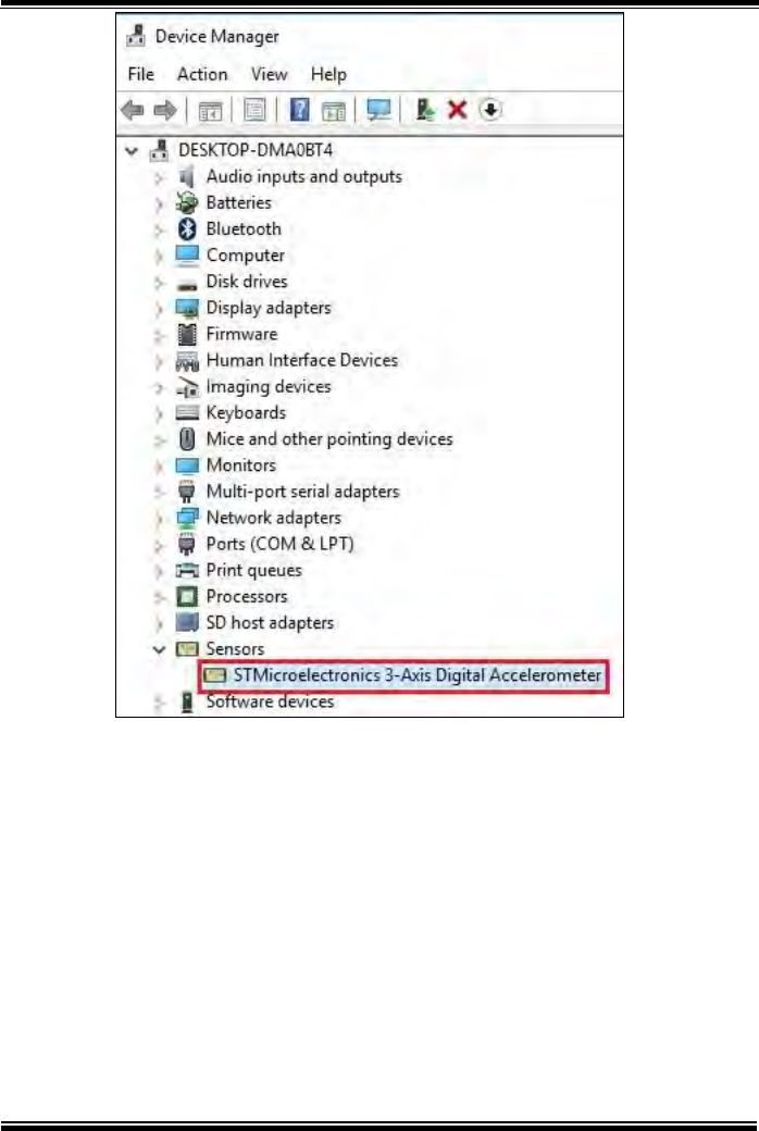
Chapter 4 Software Utilities
MH-5100 SERIES USER MANUAL
Page: 4-13
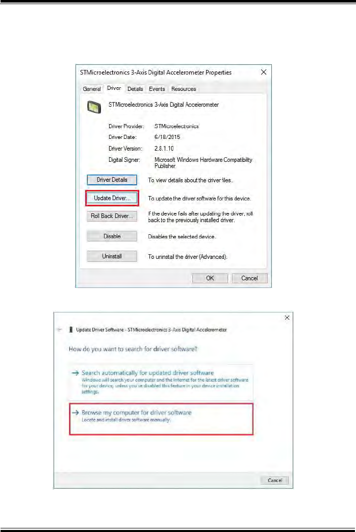
Chapter 4 Software Utilities
MH-5100 SERIES USER MANUAL
Page: 4-14
6 From STMicroelectronics 3-Axis Digital Accelerometer
Properties window, click Update Driver… from the Driver tab
to start install the G-sensor driver software for MH-5100.
7 Click Browse my computer for driver software item.
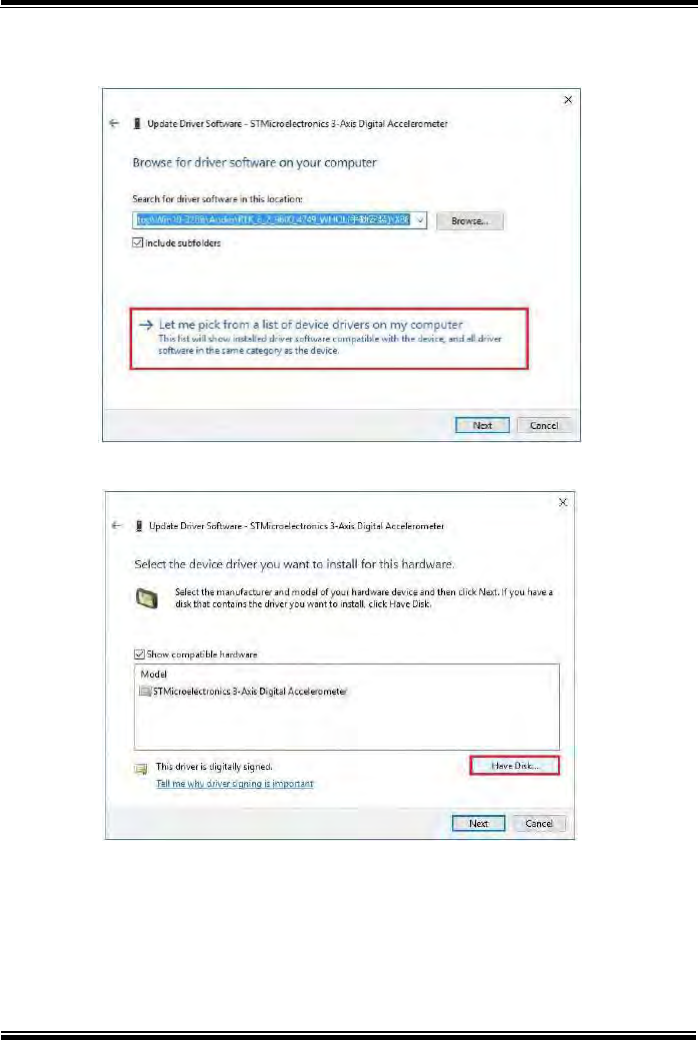
Chapter 4 Software Utilities
MH-5100 SERIES USER MANUAL
Page: 4-15
8 Click Let me pick from a list of device drivers on my
computer.
9 Click Have Disk… button.
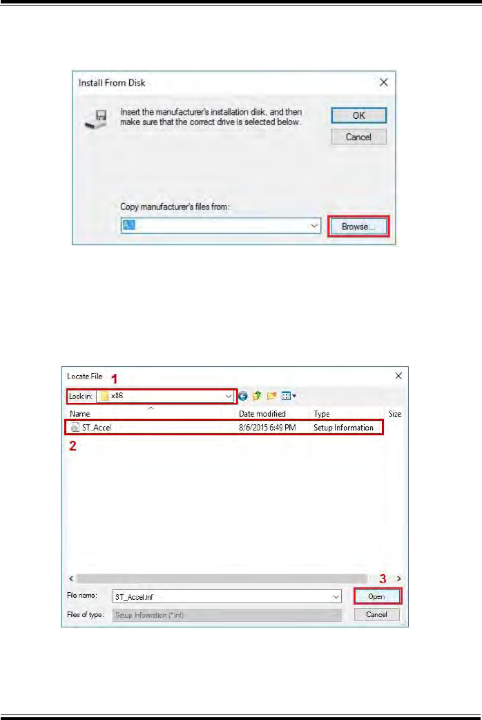
Chapter 4 Software Utilities
MH-5100 SERIES USER MANUAL
Page: 4-16
10 Click Browse… button to browse for the file directory where the
G-sensor installation driver is located.
11 Select C:\MH-5100_v1.0 > DRIVER > Device > G-sensor >
Win10-32Bit >2_Accel_SPB_SensorAPI_2.8.1.10(STEP-2) >
x86 folder from the Look in drop-down box, and select
ST_Accel.inf file. Click Open to open the file.
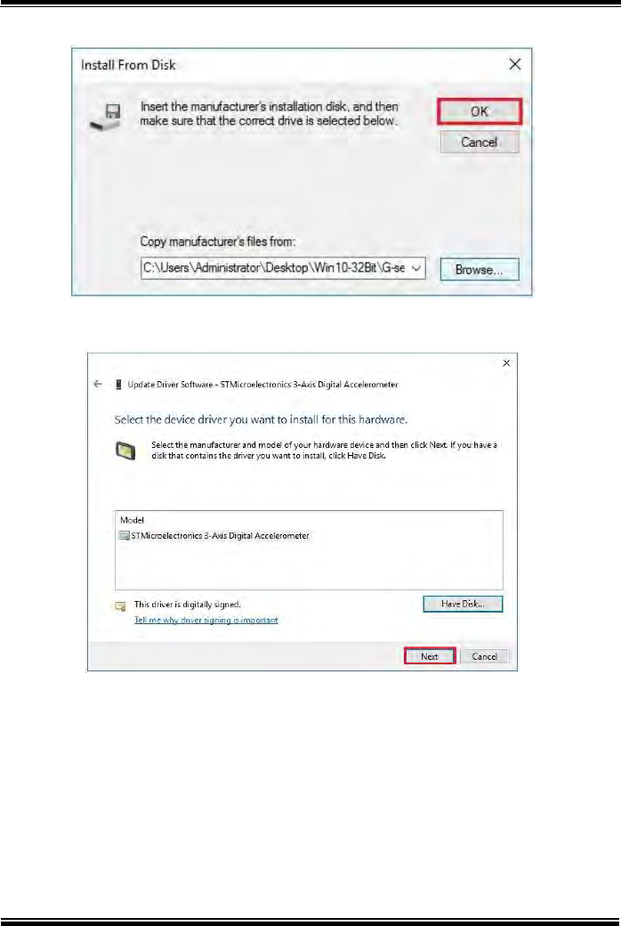
Chapter 4 Software Utilities
MH-5100 SERIES USER MANUAL
Page: 4-17
12 Click OK.
13 Click Next to continue the installation.
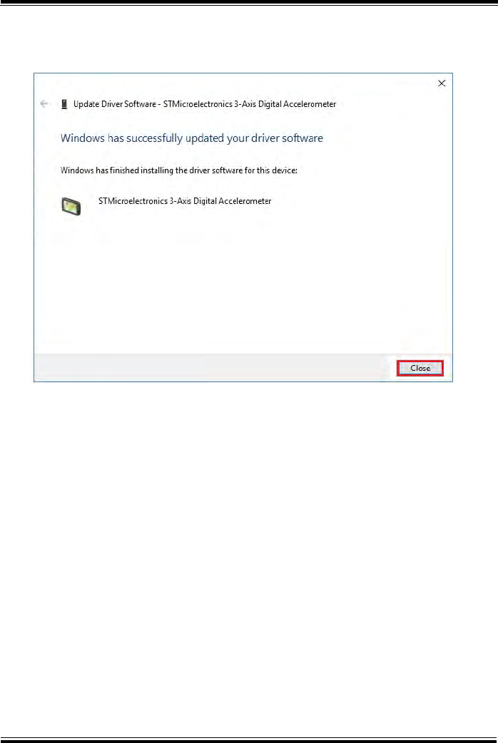
Chapter 4 Software Utilities
MH-5100 SERIES USER MANUAL
Page: 4-18
14 Windows has finished installing G-sensor driver software.
Click Close to complete.
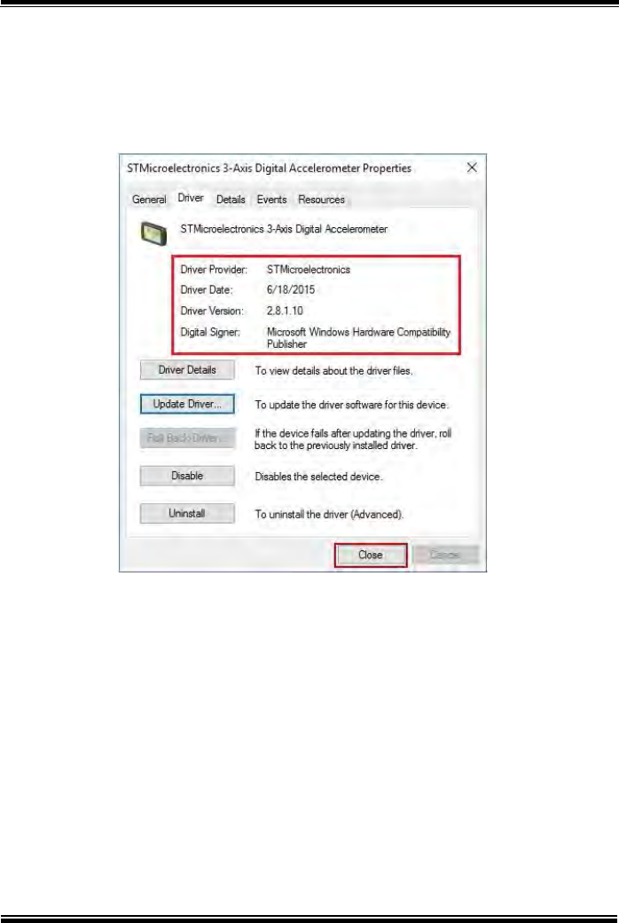
Chapter 4 Software Utilities
MH-5100 SERIES USER MANUAL
Page: 4-19
15 Go to STMicroelectronics 3-Axis Digital Accelerometer
Properties window and select Driver tab, and you will see the
STMicroelectronics G-sensor driver utility has been updated.
Click Close to exit.
16 Once the installation is completed, restart MH-5100 for the
changes to take effect.

Chapter 4 Software Utilities
MH-5100 SERIES USER MANUAL
Page: 4-20
4.5 Installing Bluetooth Software Installation
Utility
Please follow the steps below to install Bluetooth driver utilities:
1Enter the C:\MH-5100_v1.0 > DRIVER > Platform >
4_Bluetooth > Win10-32Bit >
BTW12.0.1.720_Win10_UART_USI folder.
2Click Setup.exe file for driver installation.
3Follow the on-screen instructions to install the Bluetooth driver.
4Once the installation is completed, restart MH-5100 for
the changes to take effect.

Chapter 4 Software Utilities
MH-5100 SERIES USER MANUAL
Page: 4-21
4.6 Cash Drawer API Function
Init_Drawer
int Init_Drawer(void);
Purpose
Initialize the Cash Drawer.
Return
True (1) on success, False (0) on failure
Example
if (Init_Drawer() > 0) {
//"Success!"
} else {
//"Failure!"
}
Release_Drawer
int Release_Drawer(void);
Purpose
Release the Cash Drawer.
Return
True (1) on success, False (0) on failure
Example
if (Release_Drawer() > 0) {
//"Success!"
} else {
//"Failure!"
}

Chapter 4 Software Utilities
MH-5100 SERIES USER MANUAL
Page: 4-22
Drawer_Open
int Drawer_Open(unsigned char channel, unsigned char time);
Purpose
Open the Cash Drawer.
Value
channel = 0 (Open the Cash Drawer1 <hardware is disabled>)
channel = 1 (Open the Cash Drawer2)
time:Parameter range is 5~50, unit is 10 millisecond.
(Time range: 50~500 millisecond)
Return
True (1) on success, False (0) on failure
Example
if (Drawer_Open(1, 10) == 0) {
//"Failure!"
} else {
//"Success!"
}
Drawer_Status
int Drawer_Status(void);
Purpose
Get the cash drawer status.
Return
0x31 -> Drawer is open ; 0x30 -> Drawer is close ; 0x00 ->
Failure
Example
Drawer_ST = Drawer_Status();
if (Drawer_ST == 0x31) {
//"Open!"
} else if (Drawer_ST == 0x30) {
//"Close!"
} else {
//"Failure!"
}

MH-5100 SERIES USER MANUAL
Page: 5-1
5BIOS SETUP
This chapter guides users how to configure the basic
system configurations via the BIOS Setup Utilities. The
information of the system configuration is saved in BIOS
NVRAM so that the Setup information is retained when
the system is powered off. The BIOS Setup Utilities
consist of the following menu items:
•Main Menu
•Advanced Menu
•Security Menu
•Boot Menu
•Exit Menu
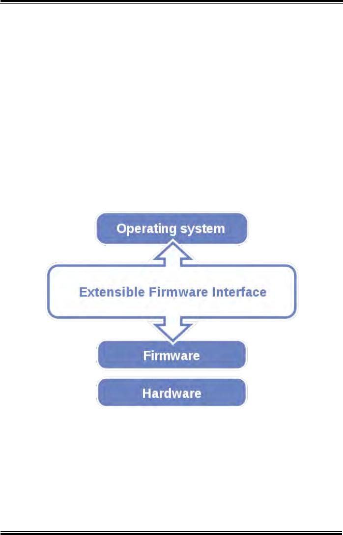
Chapter 5 BIOS Setup
MH-5100 SERIES USER MANUAL
Page: 5-2
5.1 Introduction
The board MH-5100 <Intel® Atom™ > uses an Insyde BIOS that is stored in the
Serial Peripheral Interface Flash Memory (SPI Flash) and can be updated. The SPI
Flash contains the BIOS Setup program, Power-on Self-Test (POST), the PCI
auto-configuration utility, LAN EEPROM information, and Plug and Play support.
Insyde BIOS firmware is based on the UEFI (Unified Extensible Firmware Interface)
Specifications and the Intel Platform Innovation Framework for EFI. The UEFI
specification defines an interface between an operating system and platform firmware.
The interface consists of data tables that contain platform-related information, boot
service calls, and runtime service calls that are available to the operating system and
its loader. These provide standard environment for booting an operating system and
running pre-boot applications.
The diagram below shows the Extensible Firmware Interface’s location in the
software stack.
Figure 5-1. Extensible Firmware Interface Diagram
EFI BIOS provides an user interface that allows you to modify hardware
configuration, e.g. change the system date and time, enable/disable a system
component, determine bootable device priority, set up personal password, etc., which
is convenient for engineers to perform modifications and customize the computer
system and allows technicians to troubleshoot the occurred errors when the hardware
is faulty.

Chapter 5 BIOS Setup
MH-5100 SERIES USER MANUAL
Page: 5-3
The BIOS setup menu allows users to view and modify the BIOS settings for the
computer. After the system is powered on, users can access the BIOS setup menu by
pressing <Del> or <Esc> immediately while the POST message is running before the
operating system is loading.
All the menu settings are described in details in this chapter.
5.2 Accessing Setup Utility
After the system is powered on, BIOS will enter the Power-On Self-Test (POST)
routines and the POST message will be displayed:
Figure 5-2. POST Screen

Chapter 5 BIOS Setup
MH-5100 SERIES USER MANUAL
Page: 5-4
Figure 5-3. Front Page Screen

Chapter 5 BIOS Setup
MH-5100 SERIES USER MANUAL
Page: 5-5
Press <Esc> (the one that shares the decimal point at the bottom of the number
keypad) to select SCU icon to access the Setup program. In a moment, the main
menu of the Insyde Setup Utility will appear on the screen:
InsydeH20 Setup Utility Rev. 5.0
Main
Advanced
Security
Boot
Exit
BIOS Version
51000PTA
Select the current default
language used by the
InsydeH20.
Build Date
05/11/2017
Build Time
14:10:19
MCU Version:
170210
Processor Type
System Bus Speed
System Memory Speed
Cache RAM
Total Memory
Intel® Atom™ CPU Z3736F @ 1.33
GHz 83 MHz
1333 MHz
1024 KB
2048 MB
eMMC Total Size:
32 GB
VGFX value:
1.00
VCore value:
0.71
VDDR value:
1.350
Language
<English>
System Time
[10:50:39]
System Date
[12/14/2016]
F1 Help Select Item F5/F6 Change Values F9 Setup Defaults
Esc Exit Select Menu Enter Select ►SubMenu F10 Save and Exit
BIOS Setup Menu Initialization Screen
You may move the cursor by <↑> and <↓> keys to highlight the individual menu
items. As you highlight each item, a brief description of the highlighted selection will
appear at the bottom of the screen.
The language of the BIOS setup menu interface and help messages are shown in US
English. You may use <↑> or <↓> key to select among the items and press <Enter> to
confirm and enter the sub-menu. The following table provides the list of the
navigation keys that you can use while operating the BIOS setup menu.

Chapter 5 BIOS Setup
MH-5100 SERIES USER MANUAL
Page: 5-6
BIOS Setup
Navigation Key
Description
<←> and <→>
Select a different menu screen (move the cursor from the
selected menu to the left or right).
<↑> and <↓>
Select a different item (move the cursor from the
selected item upwards or downwards)
<Enter>
Execute the command or select the sub-menu.
<F1>
Help
<F5/F6>
Change values.
<F9>
Load the default configuration values.
<F10>
Save the current values and exit the BIOS setup menu.
<Esc>
Close the sub-menu.
Trigger the confirmation to exit BIOS setup menu.
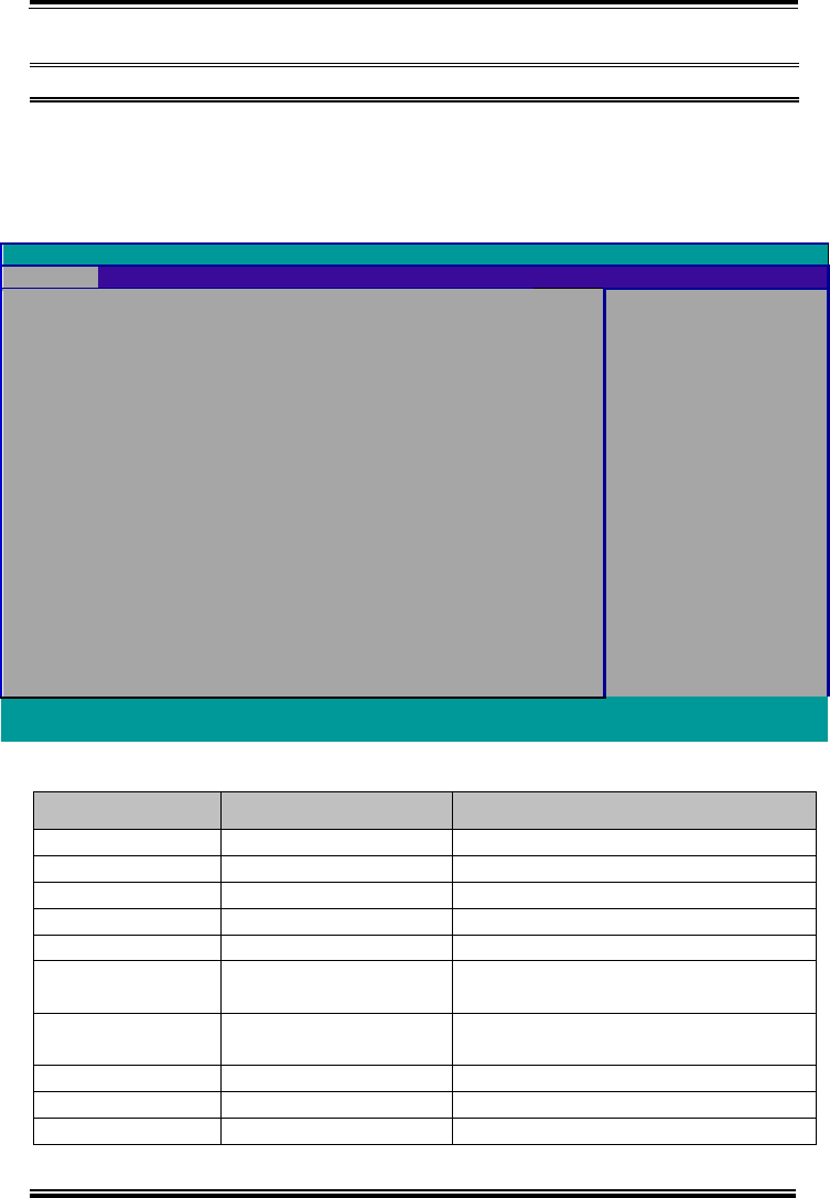
Chapter 5 BIOS Setup
MH-5100 SERIES USER MANUAL
Page: 5-7
5.3 Main
Menu Path Main
The Main menu allows you to view the BIOS Information, change the system date
and time, and view the user access privilege level. Use tab to switch between date
elements. Use <↑> or <↓> arrow keys to highlight the item and enter the value you
want in each item. This screen also displays the BIOS version (project) and BIOS
Build Date and Time.
InsydeH20 Setup Utility Rev. 5.0
Main
Advanced
Security
Boot
Exit
BIOS Version
51000PTA
Select the current default
language used by the
InsydeH20.
Build Date
05/11/2017
Build Time
14:10:19
MCU Version:
170210
Processor Type
System Bus Speed
System Memory Speed
Cache RAM
Total Memory
Intel® Atom™ CPU Z3736F @ 1.33
GHz 83 MHz
1333 MHz
1024 KB
2048 MB
eMMC Total Size:
32 GB
VGFX value:
1.00
VCore value:
0.71
VDDR value:
1.350
Language
<English>
System Time
[10:50:39]
System Date
[12/14/2016]
F1 Help Select Item F5/F6 Change Values F9 Setup Defaults
Esc Exit Select Menu Enter Select ►SubMenu F10 Save and Exit
Main Screen
BIOS Setting
Options
Description/Purpose
BIOS Version
No changeable options
Displays the BIOS Version.
Build Date
No changeable options
Displays the current Build Date.
Build Time
No changeable options
Displays the current Build Time.
MCU Version
No changeable options
Displays the MCU Version.
Processor Type
No changeable options
SOC Type on the platform.
System Bus
Speed
No changeable options
Displays Bus speed.
System Memory
Speed
No changeable options
Displays Memory Speed.
Cache RAM
No changeable options
Displays Cache RAM size.
Total Memory
No changeable options
Displays Total memory size.
eMMC Total Size
No changeable options
Displays eMMC memory size.

Chapter 5 BIOS Setup
MH-5100 SERIES USER MANUAL
Page: 5-8
BIOS Setting
Options
Description/Purpose
VGFX value
No changeable options
Displays the current VGFX voltage.
VCore value
No changeable options
Displays the current VCore voltage.
VDDR value
No changeable options
Displays the current VDDR voltage.
Language
English, Francais,
Chinese, Japanese
End users can select from four
languages.
System Time
hour, minute, second
Specifies the current time.
System Date
month, day, year
Specifies the current date.
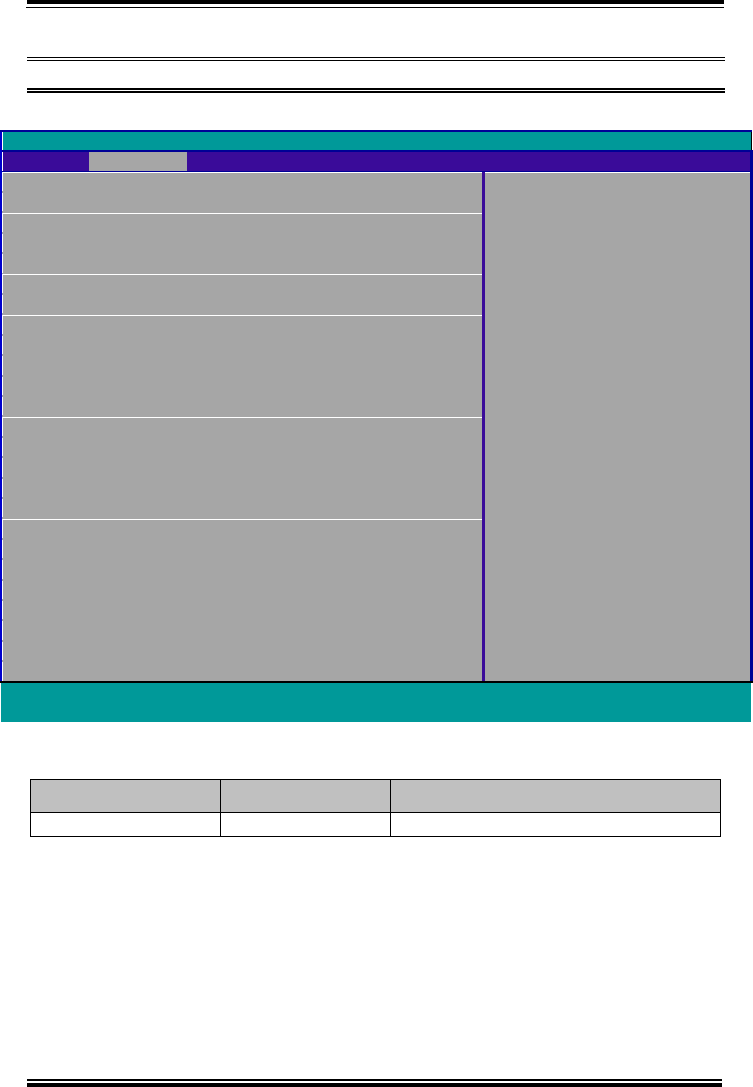
Chapter 5 BIOS Setup
MH-5100 SERIES USER MANUAL
Page: 5-9
5.4 Advanced
Menu Path Advanced
This menu provides advanced configurations for setting USB Configuration.
InsydeH20 Setup Utility Rev. 5.0
Main
Advanced
Security
Boot
Exit
►USB Configuration
F1 Help Select Item F5/F6 Change Values F9 Setup Defaults
Esc Exit Select Menu Enter Select ►SubMenu F10 Save and Exit
Advanced Menu Screen
BIOS Setting
Options
Description/Purpose
USB Configuration
Sub-Menu
USB Configuration Parameters.

Chapter 5 BIOS Setup
MH-5100 SERIES USER MANUAL
Page: 5-10
5.4.1 Advanced – USB Configuration
Menu Path Advanced > USB Configuration
The USB Configuration allows users to configure advanced USB settings such as
enabling/disabling xHCI (Extensible Host Controller Interface) Controller and xHCI
Mode.
InsydeH20 Setup Utility Rev. 5.0
Advanced
xHCI Controller
<Enabled>
xHCI Mode
<Enabled>
F1 Help Select Item F5/F6 Change Values F9 Setup Defaults
Esc Exit Select Menu Enter Select ►SubMenu F10 Save and Exit
USB Configuration Screen
BIOS Setting
Options
Description/Purpose
xHCI Controller
- Enabled
- Disabled
Enables or Disables System
ability to xHCI.
xHCI Mode
- Enabled
- Disabled
Enables or Disables xHCI mode.

Chapter 5 BIOS Setup
MH-5100 SERIES USER MANUAL
Page: 5-11
5.5 Security
Menu Path Security
From the Security menu, you are allowed to create, change or clear the supervisor
password. You will be asked to enter the configured supervisor password before you
can access the Setup Utility.
By setting a supervisor password, you will prevent other users from changing your
BIOS settings. You can configure a supervisor password and then configure a user
password. A supervisor has much more privileges over the settings in the Setup utility
than a user. Heed that a user password does not provide access to most of the features
in the Setup utility.
InsydeH20 Setup Utility Rev. 5.0
Main
Advanced
Security
Boot
Exit
Install or Change the
password and the length of
password must be greater
than one character.
Supervisor Password
Not Installed
User Password
Not Installed
Set Supervisor Password
Set User Password
F1 Help Select Item F5/F6 Change Values F9 Setup Defaults
Esc Exit Select Menu Enter Select ►SubMenu F10 Save and Exit
Security Screen

Chapter 5 BIOS Setup
MH-5100 SERIES USER MANUAL
Page: 5-12
BIOS Setting
Options
Description/Purpose
Set Supervisor Password
Password can be 1-20
alphanumeric characters.
Specifies the administrator
password.
Set User Password
Password can be 1-20
alphanumeric characters.
Specifies the user password.
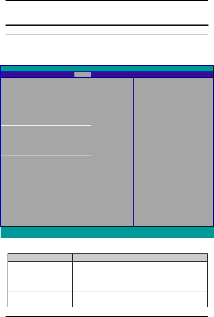
Chapter 5 BIOS Setup
MH-5100 SERIES USER MANUAL
Page: 5-13
5.6 Boot
Menu Path Boot
This menu provides control items for system boot configuration such as setting setup
prompt timeout, enabling/disabling quick boot, quiet boot, Network Stack and PXE
Boot capability, adding boot options, configuring ACPI (Advanced Configuration and
Power Management Interface) settings, USB boot and EFI device first.
InsydeH20 Setup Utility Rev. 5.0
Main
Advanced
Security
Boot
Exit
Allows InsydeH20 to skip certain
tests while booting. This will
decrease the time needed to boot
up the system.
Quick Boot
<Enabled>
Quiet Boot
<Enabled>
Network Stack
<Enabled>
PXE Boot capability
<Disabled>
Add Boot Options
<Auto>
ACPI Selection
<Acpi5.0>
USB Boot
<Enabled>
EFI Device First
<Enabled>
►EFI
F1 Help Select Item F5/F6 Change Values F9 Setup Defaults
Esc Exit Select Menu Enter Select ►SubMenu F10 Save and Exit
Boot Screen
BIOS Setting
Options
Description/Purpose
Quick Boot
- Enabled
- Disabled
This will decrease the time
needed to boot the system.
Quiet Boot
- Enabled
- Disabled
Enables or Disables booting in
Text Mode.
Network Stack
- Enabled
- Disabled
Network Stack Support:
• Windows 8 BitLocker Unlock

Chapter 5 BIOS Setup
MH-5100 SERIES USER MANUAL
Page: 5-14
BIOS Setting
Options
Description/Purpose
• UEFI IPv4/IPv6 PXE
• Legacy PXE OPROM
PXE Boot capability
- Enabled
- Disabled
• Disabled: Supports Network
Stack
• UEFI PXE: IPv4/IPv6
• Legacy: Legacy PXE OPROM
only
Add Boot Options
- First
- Last
- Auto
Position in Boot order for shell,
Network and Removables.
ACPI Selection
- Acpi 1.0B
- Acpi 3.0
- Acpi 4.0
- Acpi 5.0
Selects booting to ACPI.
USB Boot
- Enabled
- Disabled
Disables or Enables booting to
USB boot devices.
EFI Device First
- Enabled
- Disabled
Determines EFI Device first or
legacy device first.
EFI
Sub-Menu
EFI Boot order settings.
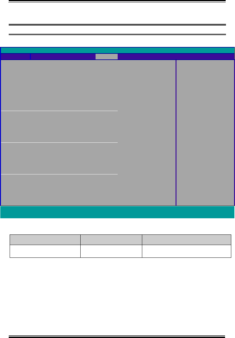
Chapter 5 BIOS Setup
MH-5100 SERIES USER MANUAL
Page: 5-15
5.6.1 Boot – EFI
Menu Path Boot > EFI
The EFI allows users to view the boot devices.
InsydeH20 Setup Utility Rev. 5.0
Boot
EFI
Windows Boot Manager
EFI USB Device (SanDisk)
F1 Help Select Item F5/F6 Change Values F9 Setup Defaults
Esc Exit Select Menu Enter Select ►SubMenu F10 Save and Exit
EFI Configuration Screen
BIOS Setting
Options
Description/Purpose
EFI
No changeable options
Displays the Boot devices.
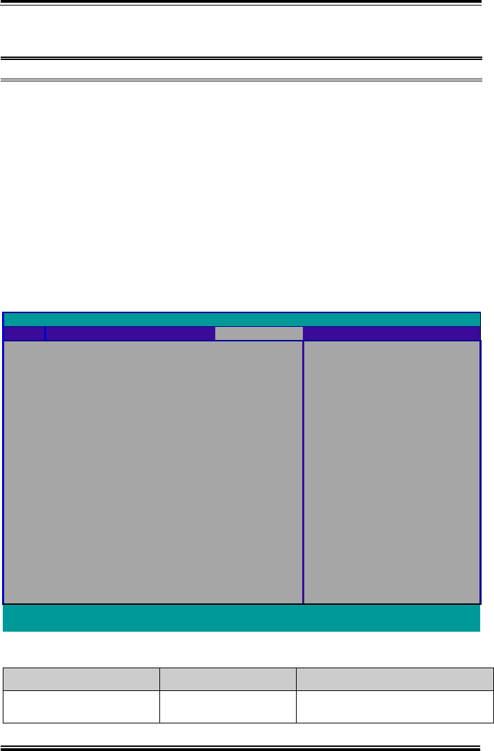
Chapter 5 BIOS Setup
MH-5100 SERIES USER MANUAL
Page: 5-16
5.7 Exit
Menu Path Exit
The Exit allows users to save or discard changed BIOS settings as well as load the
optimized defaults for BIOS settings.
Save Changed BIOS Settings
To save and validate the changed BIOS settings, select Exit Saving Changes (or
press F10) to validate the changes and then exit the system.
Discard Changed BIOS Settings
To cancel the BIOS settings you have previously configured, select Exit Discarding
Changes from this menu, or simply press Esc to exit the BIOS setup.
Load Optimal Defaults
You may simply press F9 at any time to load the Optimized Values which resets all
BIOS settings to the factory defaults.
InsydeH20 Setup Utility Rev. 5.0
Main
Advanced
Security
Boot
Exit
Exit system setup and save your
changes.
Exit Saving
Changes
Exit Discarding
Changes
Load Optimal
Defaults
F1 Help Select Item F5/F6 Change Values F9 Setup Defaults
Esc Exit Select Menu Enter Select ►SubMenu F10 Save and Exit
Exit Screen
BIOS Setting
Options
Description/Purpose
Exit Saving Changes
No changeable options
Exits and saves the changes in
NVRAM.

Chapter 5 BIOS Setup
MH-5100 SERIES USER MANUAL
Page: 5-17
BIOS Setting
Options
Description/Purpose
Exit Discarding Changes
No changeable options
Exits and discard Changes done so
far to any of the setup options.
Load Optimal Defaults
No changeable options
Loads the optimized defaults for
BIOS settings.

MH-5100 SERIES USER MANUAL
Page: A-1
Appendix A System Diagrams
This appendix contains exploded diagrams and part
numbers of the Pad, Lite Cradle and Tiltable Cradle for
MH-5100 system.
The following topics are included:
Exploded Diagrams for Integrated Pad
• Exploded Diagram for Top Cover, Touch Panel and Panel
Assembly
• Exploded Diagram for Pad PCBA Assembly
• Exploded Diagram for Bottom Cover Assembly
• Exploded Diagram for Camera Module & Barcode Scanner
Module Assembly
• Exploded Diagram for Back Cover Assembly
• Exploded Diagram for Smart Card Reader Assembly
• Exploded Diagrams For External Barcode Scanner Assembly
(1~3)
• Exploded Diagram for Scan Button Assembly
Exploded Diagrams for Lite Cradle
• Exploded Diagram for Cradle Top Cover Assembly
• Exploded Diagram for Cradle PCBA & Bottom Cover Assembly
Exploded Diagrams for Tiltable Cradle
• Exploded Diagram for Base Bottom Cover Assembly
• Exploded Diagram for Rotation Cover Assembly
• Exploded Diagram for Base Top Cover Assembly
• Exploded Diagram for Pad Lock Assembly
• Exploded Diagram for Holder Back Cover Assembly
• Exploded Diagram for Holder Top Cover Assembly
• Exploded Diagram for Card Holder Assembly
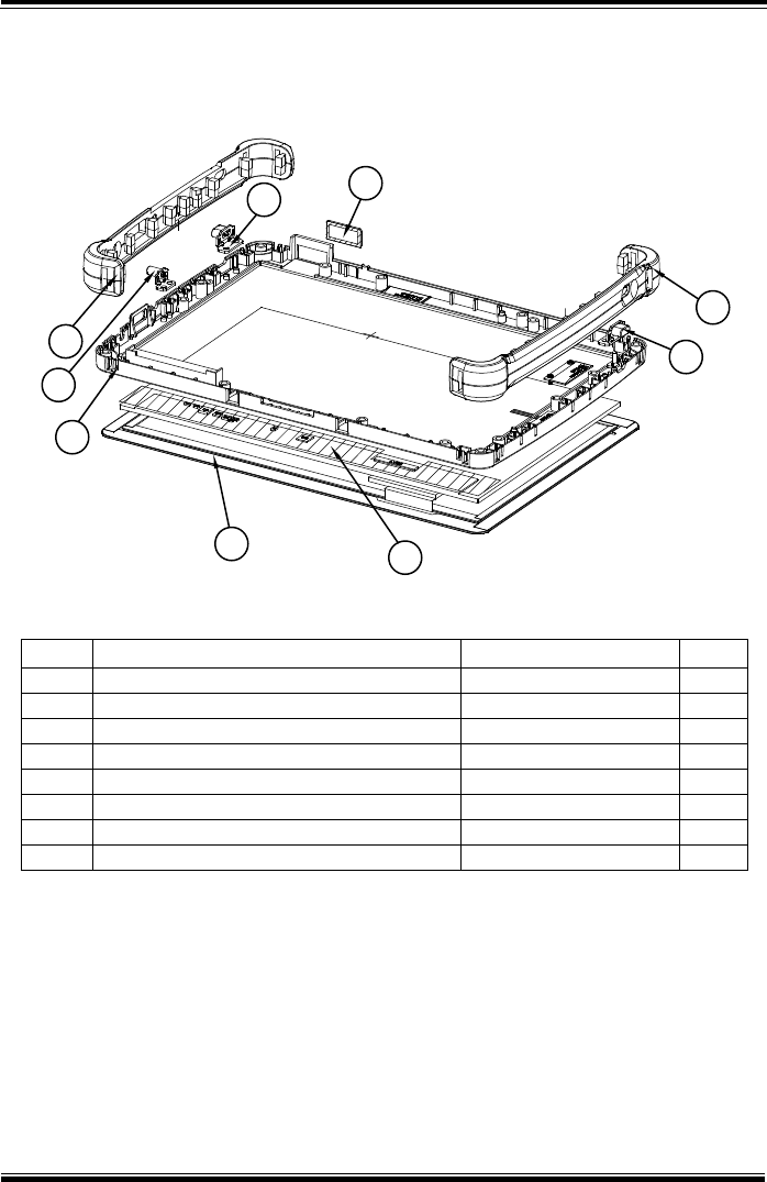
Appendix A System Diagrams
MH-5100 SERIES USER MANUAL
Page: A-2
Integrated Pad Exploded Diagrams
Exploded Diagram For Top Cover & Touch Panel & Panel Assembly
ITEM
Description
Part No.
Q’ty
1
Touch Panel
52-380-14164023
1
2
Panel
52-351-12101028
1
3
MH-5100 Top Cover
30-002-12210378
1
4
MH-5100 Bumper Right
30-013-48300378
1
5
MH-5100 Bumper Left
30-013-48200378
1
6
MH-5100 Barcode Button
30-046-28110378
2
7
MH-5100 Power Button
30-046-28210378
1
8
MH-5100 Barcode Lens
30-021-10130378
1
12
6
5
68
4
7
3
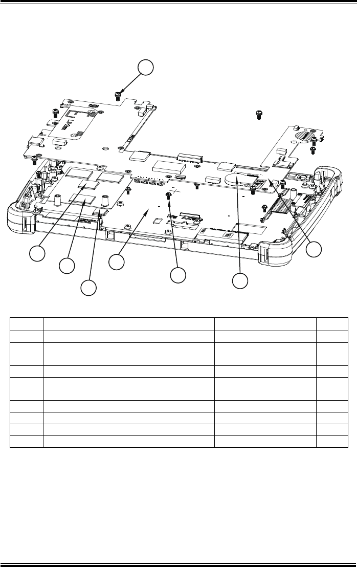
Appendix A System Diagrams
MH-5100 SERIES USER MANUAL
Page: A-3
Exploded Diagram For Pad PCBA Assembly
ITEM
Description
Part No.
Q’ty
1
MH-5100 Panel Holder
20-029-34001378
1
2
Round Head With Spring Washer Screw
(M2.5x0.45Px6mm)
22-235-25006011
7
3
MH-5100 PCBA
N/A
1
4
Round Head With Spring Washer Screw
(M2x0.4Px5mm)
22-232-20005311
11
5
Sub-Battery
27-061-37801071
1
6
Thermal Pad 20x15mm
81-006-82015001
3
7
Thermal Pad 15x15mm
81-006-81515005
1
8
Thermal Pad 10x10mm
81-006-81010003
1
2
3
5
4
1
8
6
7
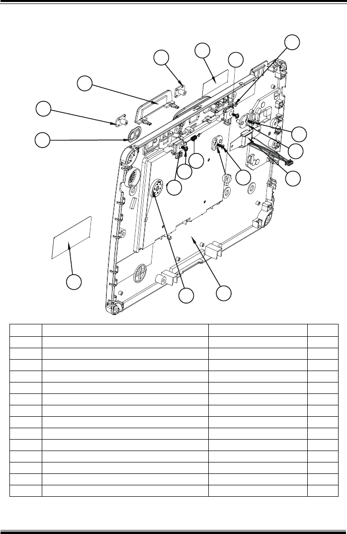
Appendix A System Diagrams
MH-5100 SERIES USER MANUAL
Page: A-4
Exploded Diagram For Bottom Cover Assembly
ITEM
Description
Part No.
Q’ty
1
MH-5100 Bottom Cover
30-002-12110378
1
2
MH-5100 Slide Key
30-002-28410378
2
3
MH-5100 Battery Hook
90-019-04110378
1
4
MH-5100 Battery Hook (Lock)
90-019-04210378
1
5
MH-5100 Battery Lock Spring
23-002-00000332
1
6
Round Washer Head Screw #1/T2.0x5mm
22-132-20005011
2
7
MH-5100 MSR-Bumper-Rubber
30-013-48100378
1
8
MSR Module
52-551-02043910
1
9
PA-8225 MSR Plate Pin (IDTECH)
20-005-07001342
2
10
Flat Head Screw #1 (T2.6x6mm)
22-112-26006011
2
11
Camera Lens
30-021-10330378
1
12
Warning Label
94-017-01601378
1
13
Rating Label
94-017-01602378
1
14
Speaker
27-021-37802071
1
7
2
2
12
11
3
6
5
10
13
14 1
8
9
10
4
6
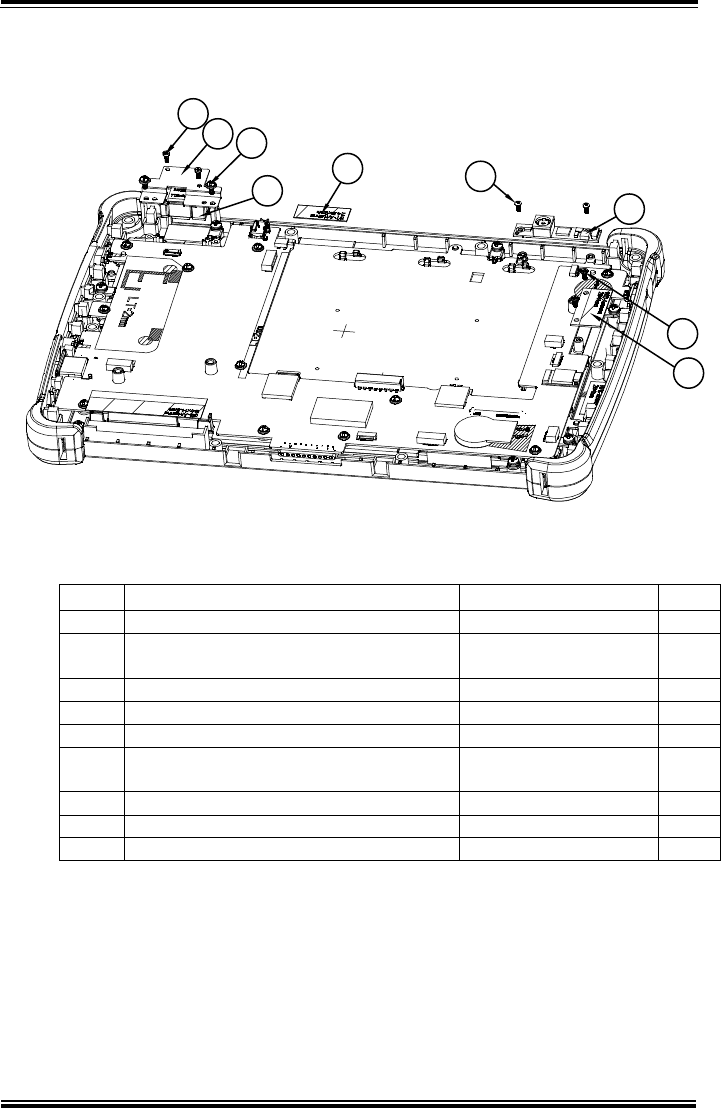
Appendix A System Diagrams
MH-5100 SERIES USER MANUAL
Page: A-5
Exploded Diagram For Camera Module & Barcode Scanner Module
Assembly
546
92
31
8
7
ITEM Description Part No. Q’ty
1 Camera PCBA 52-151-08040533 1
2 Round Head Screw
φ3.3/#1/M2x0.4Px4mm 22-232-20004811 2
3 Barcode Module 52-820-36800111 1
4 MH-5100 Barcode Fix Plate 80-005-03001378 1
5 Fillister Head Screw T1.7xL4mm 22-175-17004011 2
6 Round Head With Spring Washer Screw
(M2x0.4px5mm) 22-232-20005311 2
7 WIFI Antenna 27-029-37805071 1
8 Fillister Head Screw M2x0.4Px2.5mm 22-272-20004011 2
9 Bluetooth Antenna 27-029-37802071 1
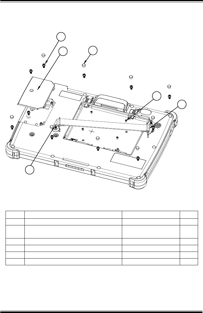
Appendix A System Diagrams
MH-5100 SERIES USER MANUAL
Page: A-6
Exploded Diagram For Back Cover Assembly
ITEM
Description
Part No.
Q’ty
1
MH-5100 Decoration Cover
30-002-28110378
1
2
Round Head With Spring Washer Screw
(M2.5x0.45Px6mm)
22-235-25006011
11
3
MH-5100 –Screw-Hole-Plug
30-013-06100378
9
4
MH-5100 Strap Bracket
80-006-06001378
2
5
Pan Head Screw M3x0.5Px6mm
22-220-30006011
2
6
M2xL3mm Flat-Head-Screw
22-215-20003011
4
1
2
3
6
4
5
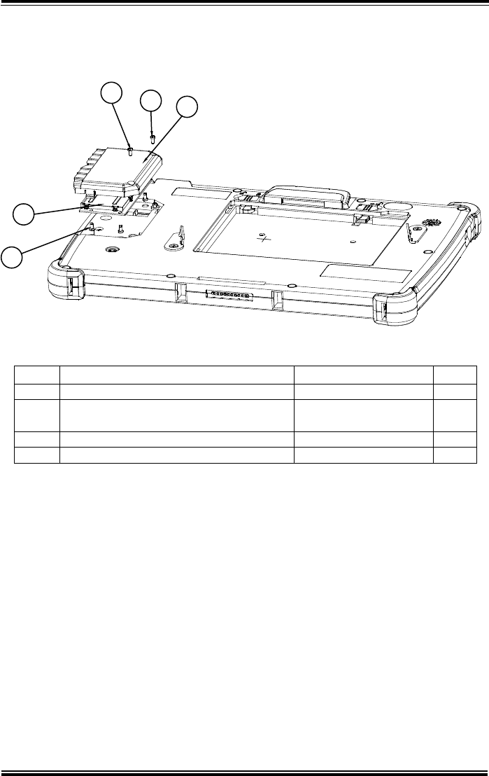
Appendix A System Diagrams
MH-5100 SERIES USER MANUAL
Page: A-7
Exploded Diagram For Smart Card Reader Assembly
ITEM
Description
Part No.
Q’ty
1
MH-5100 Smart Card Cover
30-002-28610378
1
2
Round Head Screw φ3.3 / #1 /
M2x0.4Px4mm
22-232-20004811
2
3
Smart Card Module
52-551-16000010
1
4
Pan Head Screw (T2.0x4mm)
22-125-20004011
4
221
3
4
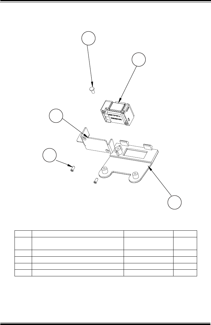
Appendix A System Diagrams
MH-5100 SERIES USER MANUAL
Page: A-8
Exploded Diagram For External Barcode Scanner Assembly (1)
No.
Component Name
P/N No.
Q’ty
1
FILLISTER HEAD
SCREW#0/T2x4mm
22-175-20004011
1
2
BARCODE SCANNER MODULE
52-820-36800111
1
3
BARCODE BARACKET
80-006-03002378
1
4
FLAT HEAD SCREW T1.7x4mm
22-115-17004011
2
5
BARCODE BOTTOM COVER
30-002-28114378
1
1
2
3
4
5
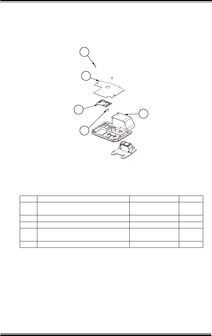
Appendix A System Diagrams
MH-5100 SERIES USER MANUAL
Page: A-9
Exploded Diagram For External Barcode Scanner Assembly (2)
No.
Component Name
P/N No.
Q’ty
1
FLAT HEAD SCREW
M2x0.4Px3mm
22-212-20003011
2
2
BARCODE TOP BRACKET
80-006-03003378
1
3
MR-5100RX-3-PCB
MR-5100RA-31N
1
4
FILLISTER HEAD
SCREW/T2.9x4mm
22-175-20004011
2
5
BARCODE TOP COVER
30-002-28115378
1
1
2
35
4
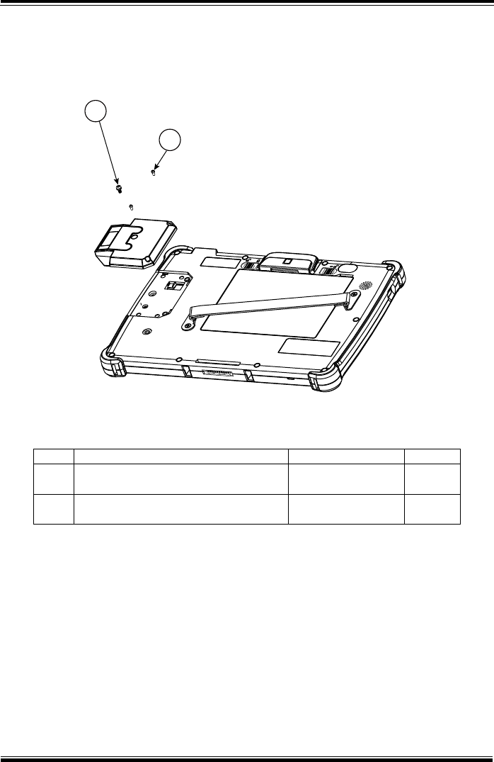
Appendix A System Diagrams
MH-5100 SERIES USER MANUAL
Page: A-10
Exploded Diagram For External Barcode Scanner Assembly (3)
No.
Component Name
P/N No.
Q’ty
1
Round Head With Spring Washer
Screw (M2.5x0.45Px6mm)
22-235-25006011
1
2
ROUND HEAD SCREW
φ3.3/#1/M2x0.4Px4mm
22-232-20004811
2
1
2
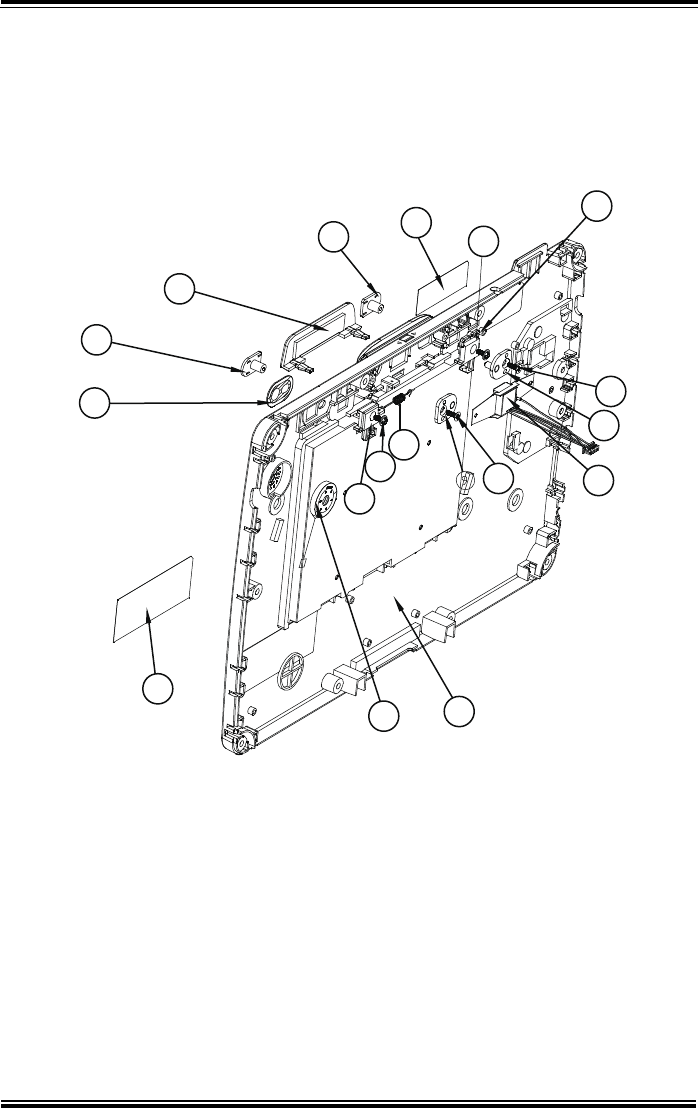
Appendix A System Diagrams
MH-5100 SERIES USER MANUAL
Page: A-11
Exploded Diagram For Scan Button Assembly
7
2
212
11
3
6
5
10
13
14 1
8
9
10
4
6

Appendix A System Diagrams
MH-5100 SERIES USER MANUAL
Page: A-12
ITEM
Description
Part No.
Q’ty
1
MH-5100 Bottom Cover (VR(PANTONE
White 5315U)
30-002-12410378
1
2
MH-5100 Slide Key-(PANTONE 5315U)
30-002-28810378
2
3
MH-5100 Battery Hook
90-019-04110378
1
4
MH-5100 Battery Hook (Lock)
90-019-04210378
1
5
MH-5100 Battery Lock Spring
23-002-00000332
1
6
Round Washer Head Screw #1/T2.0x5mm
22-132-20005011
2
7
MH-5100 Barcode-Button-Rubber
90-013-01300378
1
8
MH-5100 MSR-Hole-Plug
90-013-01200378
1
9
Barcode PCBA
MR-5100RA-81N
1
10
Flat Head Screw #1 (T2.5x5mm)
22-172-25005011
2
11
Lens_opaque
30-021-10430378
1
12
Warning Label
94-017-01601378
1
13
Rating Label
94-017-01602378
1
14
Speaker
27-021-37802071
1
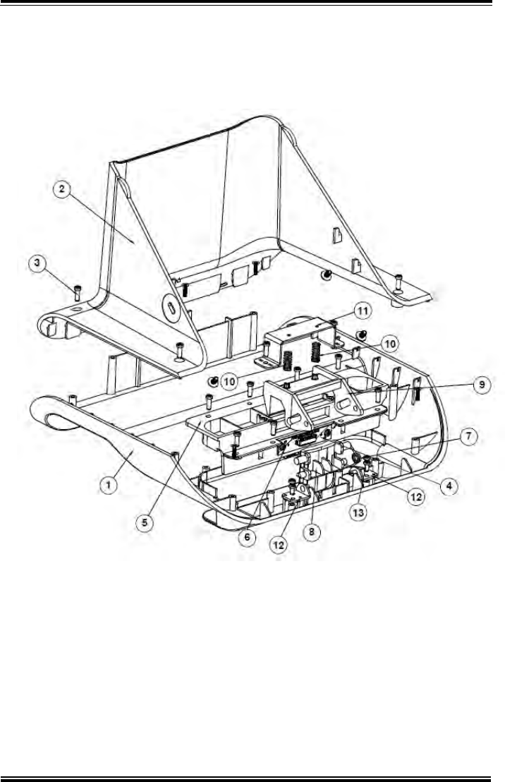
Appendix A System Diagrams
MH-5100 SERIES USER MANUAL
Page: A-13
Lite Cradle Exploded Diagrams
Exploded Diagram For Cradle Top Cover Assembly

Appendix A System Diagrams
MH-5100 SERIES USER MANUAL
Page: A-14
ITEM
Description
Part No.
Q’ty
1
MH-5100-Lite-Cradle-Top-Cover
30-002-28310378
1
2
MH-5100-Lite-Cradle-Rear-Cover
30-002-28210378
1
3
T2.6xL8mm Pan-Head-Screw
22-135-26008011
14
4
POGO Pin PCBA
10-625-01010025
1
5
MH-5100-Lite-Cradle-Hole-Cover
30-002-28510378
1
6
Pan Head screw (T2.0x4mm)
22-125-20004011
2
7
MH-5100-Lite-Cradle-Ejection-Spring
23-000-00010622
1
8
MH-5100-Lite-Cradle-Lock-Button
30-046-09230378
1
9
MH-5100-Lite-Cradle-Button-Hook
30-046-09130378
1
10
MT-590X Battery Lock Spring
23-000-01000132
2
11
MH-5100-Lite-Cradle-Lock-Spring-Cover
80-004-03001378
1
12
MH-5100-Lite-Cradle-Rotate-Plate
80-005-03002378
2
13
T2.3xL5mm Pan-Head-Screw
22-135-23005011
4
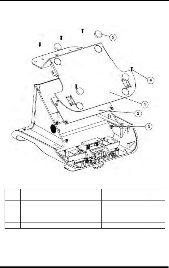
Appendix A System Diagrams
MH-5100 SERIES USER MANUAL
Page: A-15
Exploded Diagram For Cradle PCBA & Bottom Cover Assembly
ITEM
Description
Part No.
Q’ty
1
MH-5100-Lite-Cradle-Metal-Plate
80-005-03003378
1
2
Lite Cradle PCBA
N/A
1
3
Round Washer Head Screw
(M3x0.5Px6mm)
22-232-30006311
4
4
T2.6xL8mm Flat-Head-Screw
22-115-26008011
5
5
Rubber Foot φ=16x3.5mm (Black)
30-004-06800000
4
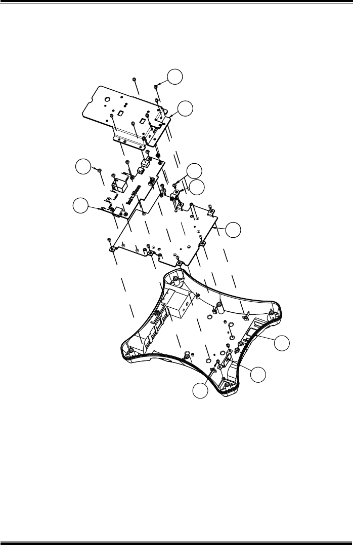
Appendix A System Diagrams
MH-5100 SERIES USER MANUAL
Page: A-16
Tiltable Cradle Exploded Diagrams
Exploded Diagram For Base Bottom Cover Assembly
10
9
6
5
8
7
4
3
2
1

Appendix A System Diagrams
MH-5100 SERIES USER MANUAL
Page: A-17
No.
Component Name
P/N No.
Q’ty
1
BASE BOT
30-027-28160378
1
2
KING LOCK PLATE
80-005-03006378
1
3
TAPPING 3xL5
22-121-30005011
8
4
BOTTOM PLATE
80-005-03004378
1
5
CABLE CLAMP
90-023-04100378
1
6
TAPPING 3xL8
22-122-30008005
1
7
PCBA
MR-5100RA-11N
1
8
SCREW M3xL5
22-242-30005311
5
9
CRADLE BASE BRACKET
80-006-03001378
1
10
SCREW M3xL6
22-232-30060211
6
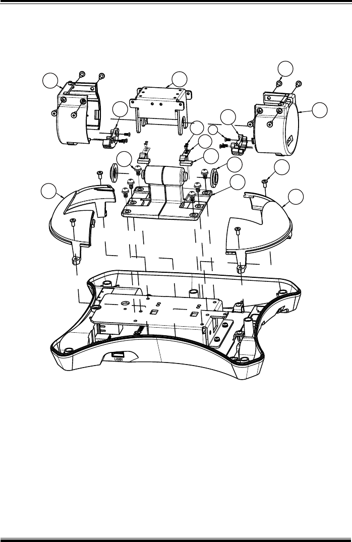
Appendix A System Diagrams
MH-5100 SERIES USER MANUAL
Page: A-18
Exploded Diagram For Rotation Cover Assembly
10
11
12
15
13
14
13
6
8
1
2
5
4
3
9
7

Appendix A System Diagrams
MH-5100 SERIES USER MANUAL
Page: A-19
No.
Component Name
P/N No.
Q’ty
1
CRADLE-STAND
80-017-01001378
1
2
BEARING
30-002-09130378
2
3
CUSHION
30-013-06110378
2
4
SPRING PLATE
80-005-06001378
2
5
SCREW M2xL3
22-212-20003911
4
6
SCREW M4xL8
22-232-40008211
6
7
ROTATION COVER R
30-002-28111378
1
8
ROTATION-COVER-R-ANY
30-002-14230378
1
9
TAPPING T2.5xL5
22-172-25005011
6
10
ROTATION-COVER-L
30-002-12130378
1
11
ROTATION-COVER-L-ANY
30-002-14130378
1
12
CRADLE-STAND-PLATE
80-005-03005378
1
13
SCREW M3xL6
22-272-30006311
12
14
BASE SPHERE RIGHT
30-027-28210378
1
15
BASE SPHERE LEFT
30-027-28110378
1
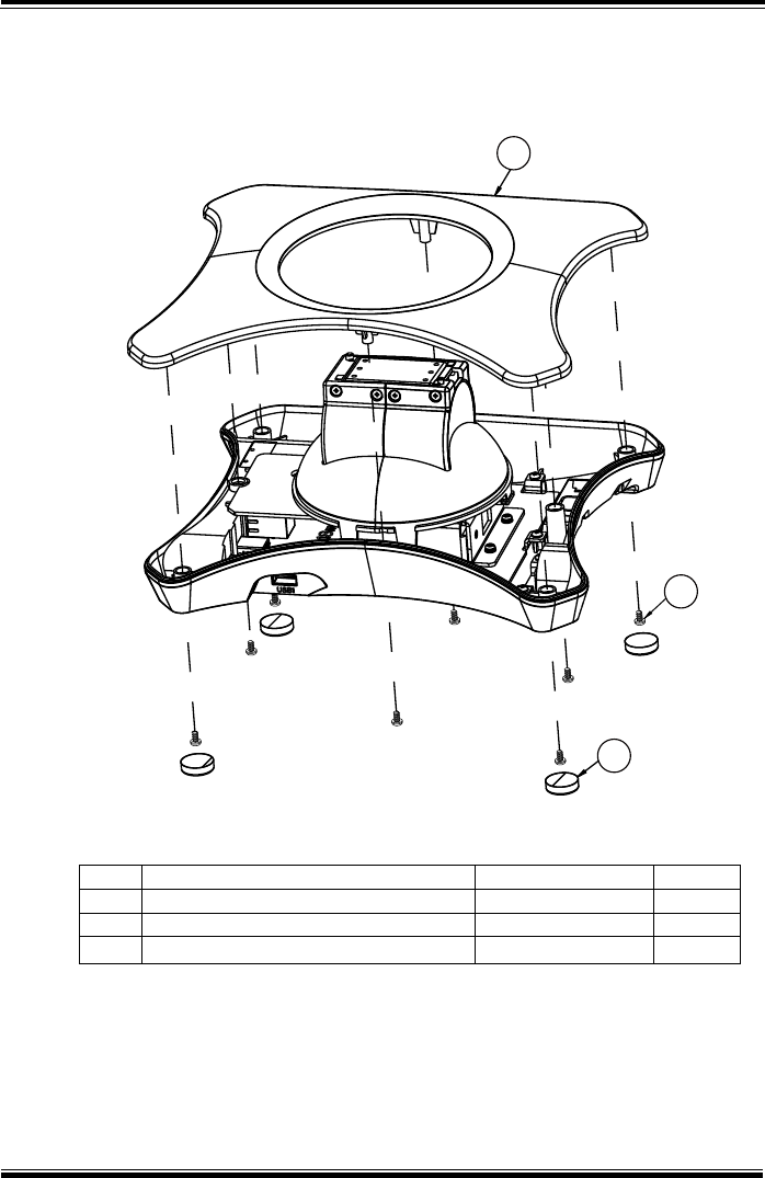
Appendix A System Diagrams
MH-5100 SERIES USER MANUAL
Page: A-20
Exploded Diagram For Base Top Cover Assembly
No.
Component Name
P/N No.
Q’ty
1
BASE TOP
30-027-28310378
1
2
TAPPING T3xL5
22-121-30005011
8
3
RUBBER FOOT (Φ 17.5x5.3mm)
30-004-06100378
4
1
2
3
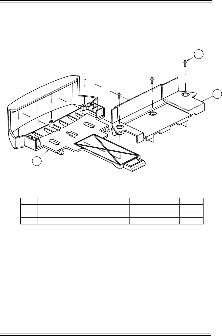
Appendix A System Diagrams
MH-5100 SERIES USER MANUAL
Page: A-21
Exploded Diagram For Pad Lock Assembly
No.
Component Name
P/N No.
Q’ty
1
HOLDER_LOCK_TOP
30-012-28410378
1
2
HOLDER-LOCK-BOTTOM
30-012-28310378
1
3
TAPPING T2.5xL5
22-172-25005011
3
3
2
1
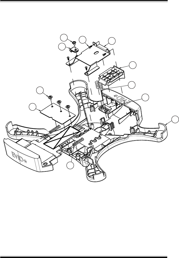
Appendix A System Diagrams
MH-5100 SERIES USER MANUAL
Page: A-22
Exploded Diagram For Holder Back Cover Assembly
7
865
11
10
9
1
4
3
2

Appendix A System Diagrams
MH-5100 SERIES USER MANUAL
Page: A-23
No.
Component Name
P/N No.
Q’ty
1
HOLDER_BACK_COVER
30-012-28110378
1
2
SWITCH
30-002-28113378
1
3
SWITCH-REPOSITION
30-002-28112378
1
4
BUTTON-SPRING
23-002-00000142
2
5
PUSH-BUTTON-PLATE
80-005-03007378
1
6
TAPPING T2.5xL5
22-172-25005011
4
7
CABLE CLAMP
90-023-04100378
1
8
SCREW M3xL5
22-242-30005311
1
9
HOLDER-LOCK-SPRING
23-002-00000252
2
10
HOLDER_LOCK_CASE
80-032-03001378
1
11
TAPPING T2.6xL5
22-132-26005011
3
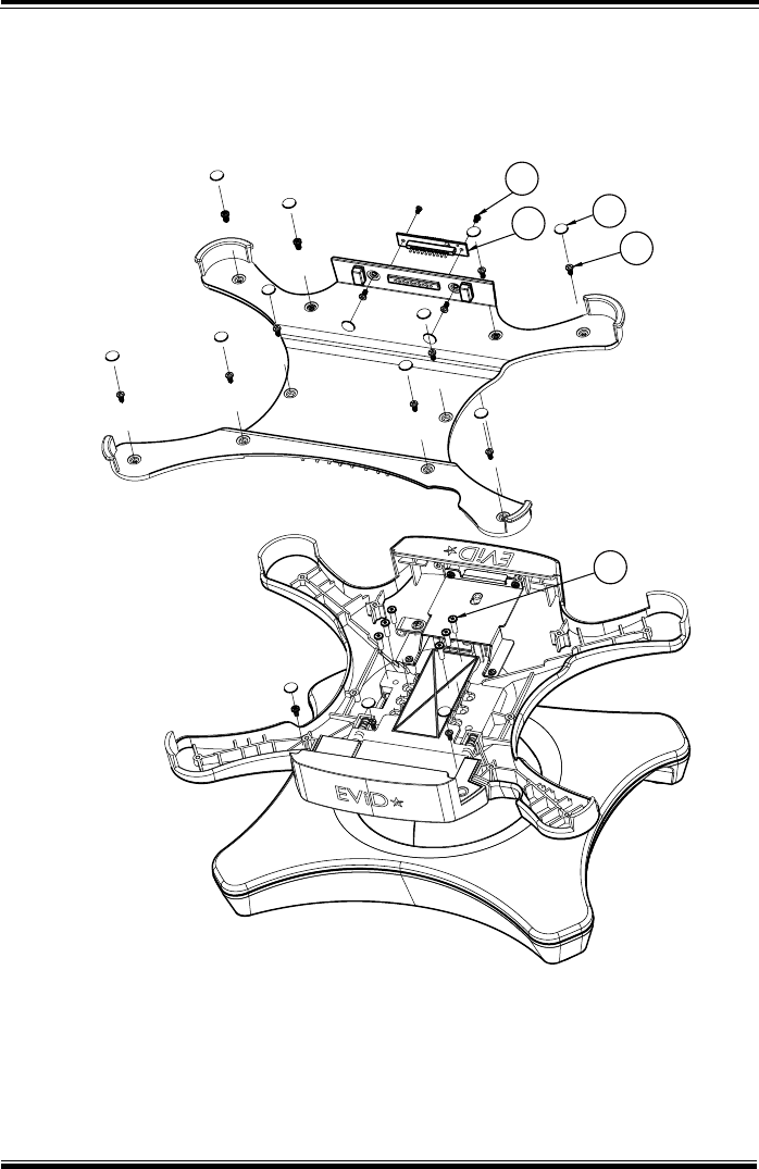
Appendix A System Diagrams
MH-5100 SERIES USER MANUAL
Page: A-24
Exploded Diagram For Holder Top Cover Assembly
3
25
4
1

Appendix A System Diagrams
MH-5100 SERIES USER MANUAL
Page: A-25
No.
Component Name
P/N No.
Q’ty
1
SCREW M3xL10
22-272-30010018
6
2
CRADLE CHARGE PCB
N/A
1
3
TAPPING T2xL3
22-172-20003011
2
4
TAPPING T2.5xL5
22-172-25005011
15
5
MYLAR-D8T0.3
30-056-02100378
15
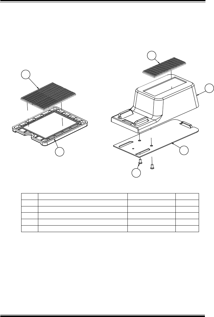
Appendix A System Diagrams
MH-5100 SERIES USER MANUAL
Page: A-26
Exploded Diagram For Card Holder Assembly
No.
Component Name
P/N No.
Q’ty
1
CARD-LICENSE
30-002-28910378
1
2
VELCRO
30-082-31100378
3
3
CARD HOLDER
30-012-28510378
1
4
CARD HOLDER PLATE
80-005-03008378
1
5
FLAT HEAD SCREW#2/T3.0x6mm
22-112-30006011
2
2
2
3
4
5
1

MH-5100 SERIES USER MANUAL
Page: B-1
Appendix B Technical Summary
This appendix will give you a brief introduction of the
allocation maps for MH-5100 resources.
The following topics are included:
• Interrupt Map
• I/O Map
• Memory Map
• System BIOS Update Procedure

Appendix B Technical Summary
MH-5100 SERIES USER MANUAL
Page: B-2
Interrupt Map
IRQ
Assignment
IRQ 0
System timer
IRQ 4
Communications Port (COM1)
IRQ 8
High precision event timer
IRQ 9
GPIOVirtual Controller
IRQ 24
Intel(R) SST Audio Device (WDM)
IRQ 25
Intel(R) SST Audio Device (WDM)
IRQ 26
Intel(R) SST Audio Device (WDM)
IRQ 27
Intel(R) SST Audio Device (WDM)
IRQ 28
Intel(R) SST Audio Device (WDM)
IRQ 29
Intel(R) SST Audio Device (WDM)
IRQ 32
I2C Controller
IRQ 33
I2C Controller
IRQ 34
I2C Controller
IRQ 35
I2C Controller
IRQ 36
I2C Controller
IRQ 39
UART Controller
IRQ 40
UART Controller
IRQ 44
Intel(R) SD Host Controller
IRQ 46
Intel(R) SD Host Controller
IRQ 47
Intel(R) SD Host Controller
IRQ 48
GPIO Controller
IRQ 49
GPIO Controller
IRQ 50
GPIO Controller
IRQ 54
Microsoft ACPI-Compliant System
IRQ 55
Microsoft ACPI-Compliant System
IRQ 56
Microsoft ACPI-Compliant System
IRQ 57
Microsoft ACPI-Compliant System
IRQ 58
Microsoft ACPI-Compliant System
IRQ 59
Microsoft ACPI-Compliant System
IRQ 60
Microsoft ACPI-Compliant System
IRQ 61
Microsoft ACPI-Compliant System
IRQ 62
Microsoft ACPI-Compliant System

Appendix B Technical Summary
MH-5100 SERIES USER MANUAL
Page: B-3
IRQ
Assignment
IRQ 63
Microsoft ACPI-Compliant System
IRQ 64
Microsoft ACPI-Compliant System
IRQ 65
Microsoft ACPI-Compliant System
IRQ 66
Microsoft ACPI-Compliant System
IRQ 67
Intel(R) Power Management IC Device
IRQ 67
Intel(R) Power Management IC Device
IRQ 67
Intel(R) Power Management IC Device
IRQ 67
Microsoft ACPI-Compliant System
IRQ 68
I2C HID Device
IRQ 68
Microsoft ACPI-Compliant System
IRQ 69
Broadcom 802.11 b/g/n Wireless SDIO Adapter
IRQ 69
Microsoft ACPI-Compliant System
IRQ 70
Microsoft ACPI-Compliant System
IRQ 71
Microsoft ACPI-Compliant System
IRQ 72
Microsoft ACPI-Compliant System
IRQ 73
Microsoft ACPI-Compliant System
IRQ 74
Microsoft ACPI-Compliant System
IRQ 75
Microsoft ACPI-Compliant System
IRQ 76
Microsoft ACPI-Compliant System
IRQ 77
Microsoft ACPI-Compliant System
IRQ 78
Microsoft ACPI-Compliant System
IRQ 79
Microsoft ACPI-Compliant System
IRQ 80
Microsoft ACPI-Compliant System
IRQ 81
Microsoft ACPI-Compliant System
IRQ 82
Microsoft ACPI-Compliant System
IRQ 83
Microsoft ACPI-Compliant System
IRQ 84
Microsoft ACPI-Compliant System
IRQ 85
Microsoft ACPI-Compliant System
IRQ 86
Intel(R) Dynamic Platform & Thermal Framework Processor
Participant Driver
IRQ 86
Microsoft ACPI-Compliant System
IRQ 87
Microsoft ACPI-Compliant System

Appendix B Technical Summary
MH-5100 SERIES USER MANUAL
Page: B-4
IRQ
Assignment
IRQ 88
Microsoft ACPI-Compliant System
IRQ 89
Microsoft ACPI-Compliant System
IRQ 90
Microsoft ACPI-Compliant System
IRQ 91
Microsoft ACPI-Compliant System
IRQ 92
Microsoft ACPI-Compliant System
IRQ 93
Microsoft ACPI-Compliant System
IRQ 94
Microsoft ACPI-Compliant System
IRQ 95
Microsoft ACPI-Compliant System
IRQ 96
Microsoft ACPI-Compliant System
IRQ 97
Microsoft ACPI-Compliant System
IRQ 98
Microsoft ACPI-Compliant System
IRQ 99
Microsoft ACPI-Compliant System
IRQ 100
Microsoft ACPI-Compliant System
IRQ 101
Microsoft ACPI-Compliant System
IRQ 102
Microsoft ACPI-Compliant System
IRQ 103
Microsoft ACPI-Compliant System
IRQ 104
Microsoft ACPI-Compliant System
IRQ 105
Microsoft ACPI-Compliant System
IRQ 106
Microsoft ACPI-Compliant System
IRQ 107
Microsoft ACPI-Compliant System
IRQ 108
Microsoft ACPI-Compliant System
IRQ 109
Microsoft ACPI-Compliant System
IRQ 110
Microsoft ACPI-Compliant System
IRQ 111
Microsoft ACPI-Compliant System
IRQ 112
Microsoft ACPI-Compliant System
IRQ 113
Microsoft ACPI-Compliant System
IRQ 114
Microsoft ACPI-Compliant System
IRQ 115
Microsoft ACPI-Compliant System
IRQ 116
Microsoft ACPI-Compliant System
IRQ 117
Microsoft ACPI-Compliant System
IRQ 118
Microsoft ACPI-Compliant System
IRQ 119
Microsoft ACPI-Compliant System
IRQ 120
Microsoft ACPI-Compliant System

Appendix B Technical Summary
MH-5100 SERIES USER MANUAL
Page: B-5
IRQ
Assignment
IRQ 121
Microsoft ACPI-Compliant System
IRQ 122
Microsoft ACPI-Compliant System
IRQ 123
Microsoft ACPI-Compliant System
IRQ 124
Microsoft ACPI-Compliant System
IRQ 125
Microsoft ACPI-Compliant System
IRQ 126
Microsoft ACPI-Compliant System
IRQ 127
Microsoft ACPI-Compliant System
IRQ 128
Microsoft ACPI-Compliant System
IRQ 129
Microsoft ACPI-Compliant System
IRQ 130
Microsoft ACPI-Compliant System
IRQ 131
Microsoft ACPI-Compliant System
IRQ 132
Microsoft ACPI-Compliant System
IRQ 133
Microsoft ACPI-Compliant System
IRQ 134
Microsoft ACPI-Compliant System
IRQ 135
Microsoft ACPI-Compliant System
IRQ 136
Microsoft ACPI-Compliant System
IRQ 137
Microsoft ACPI-Compliant System
IRQ 138
Microsoft ACPI-Compliant System
IRQ 139
Microsoft ACPI-Compliant System
IRQ 140
Microsoft ACPI-Compliant System
IRQ 141
Microsoft ACPI-Compliant System
IRQ 142
Microsoft ACPI-Compliant System
IRQ 143
Microsoft ACPI-Compliant System
IRQ 144
Microsoft ACPI-Compliant System
IRQ 145
Microsoft ACPI-Compliant System
IRQ 146
Microsoft ACPI-Compliant System
IRQ 147
Microsoft ACPI-Compliant System
IRQ 148
Microsoft ACPI-Compliant System
IRQ 149
Microsoft ACPI-Compliant System
IRQ 150
Microsoft ACPI-Compliant System
IRQ 151
Microsoft ACPI-Compliant System
IRQ 152
Microsoft ACPI-Compliant System

Appendix B Technical Summary
MH-5100 SERIES USER MANUAL
Page: B-6
IRQ
Assignment
IRQ 153
Microsoft ACPI-Compliant System
IRQ 154
Microsoft ACPI-Compliant System
IRQ 155
Microsoft ACPI-Compliant System
IRQ 156
Microsoft ACPI-Compliant System
IRQ 157
Microsoft ACPI-Compliant System
IRQ 158
Microsoft ACPI-Compliant System
IRQ 159
Microsoft ACPI-Compliant System
IRQ 160
Microsoft ACPI-Compliant System
IRQ 161
Microsoft ACPI-Compliant System
IRQ 162
Microsoft ACPI-Compliant System
IRQ 163
Microsoft ACPI-Compliant System
IRQ 164
Microsoft ACPI-Compliant System
IRQ 165
Microsoft ACPI-Compliant System
IRQ 166
Microsoft ACPI-Compliant System
IRQ 167
Microsoft ACPI-Compliant System
IRQ 168
Microsoft ACPI-Compliant System
IRQ 169
Microsoft ACPI-Compliant System
IRQ 170
Microsoft ACPI-Compliant System
IRQ 171
Microsoft ACPI-Compliant System
IRQ 172
Microsoft ACPI-Compliant System
IRQ 173
Microsoft ACPI-Compliant System
IRQ 174
Microsoft ACPI-Compliant System
IRQ 175
Microsoft ACPI-Compliant System
IRQ 176
Microsoft ACPI-Compliant System
IRQ 177
Microsoft ACPI-Compliant System
IRQ 178
Microsoft ACPI-Compliant System
IRQ 179
Microsoft ACPI-Compliant System
IRQ 180
Microsoft ACPI-Compliant System
IRQ 181
Microsoft ACPI-Compliant System
IRQ 182
Microsoft ACPI-Compliant System
IRQ 183
Microsoft ACPI-Compliant System
IRQ 184
Microsoft ACPI-Compliant System
IRQ 185
Microsoft ACPI-Compliant System

Appendix B Technical Summary
MH-5100 SERIES USER MANUAL
Page: B-7
IRQ
Assignment
IRQ 186
Microsoft ACPI-Compliant System
IRQ 187
Microsoft ACPI-Compliant System
IRQ 188
Microsoft ACPI-Compliant System
IRQ 189
Microsoft ACPI-Compliant System
IRQ 190
Microsoft ACPI-Compliant System
IRQ 191
Microsoft ACPI-Compliant System
IRQ 192
Microsoft ACPI-Compliant System
IRQ 193
Microsoft ACPI-Compliant System
IRQ 194
Microsoft ACPI-Compliant System
IRQ 195
Microsoft ACPI-Compliant System
IRQ 196
Microsoft ACPI-Compliant System
IRQ 197
Microsoft ACPI-Compliant System
IRQ 198
Microsoft ACPI-Compliant System
IRQ 199
Microsoft ACPI-Compliant System
IRQ 200
Microsoft ACPI-Compliant System
IRQ 201
Microsoft ACPI-Compliant System
IRQ 202
Microsoft ACPI-Compliant System
IRQ 203
Microsoft ACPI-Compliant System
IRQ 204
Microsoft ACPI-Compliant System
IRQ 256
Microsoft ACPI-Compliant System
IRQ 257
Microsoft ACPI-Compliant System
IRQ 258
Microsoft ACPI-Compliant System
IRQ 259
Microsoft ACPI-Compliant System
IRQ 260
Microsoft ACPI-Compliant System
IRQ 261
Microsoft ACPI-Compliant System
IRQ 262
Microsoft ACPI-Compliant System
IRQ 263
Microsoft ACPI-Compliant System
IRQ 264
Microsoft ACPI-Compliant System
IRQ 265
Microsoft ACPI-Compliant System
IRQ 266
Microsoft ACPI-Compliant System
IRQ 267
Microsoft ACPI-Compliant System
IRQ 268
Microsoft ACPI-Compliant System

Appendix B Technical Summary
MH-5100 SERIES USER MANUAL
Page: B-8
IRQ
Assignment
IRQ 269
Microsoft ACPI-Compliant System
IRQ 270
Microsoft ACPI-Compliant System
IRQ 271
Microsoft ACPI-Compliant System
IRQ 272
Microsoft ACPI-Compliant System
IRQ 273
Microsoft ACPI-Compliant System
IRQ 274
Microsoft ACPI-Compliant System
IRQ 275
Microsoft ACPI-Compliant System
IRQ 276
Microsoft ACPI-Compliant System
IRQ 277
Microsoft ACPI-Compliant System
IRQ 278
Microsoft ACPI-Compliant System
IRQ 279
Microsoft ACPI-Compliant System
IRQ 280
Microsoft ACPI-Compliant System
IRQ 281
Microsoft ACPI-Compliant System
IRQ 282
Microsoft ACPI-Compliant System
IRQ 283
Microsoft ACPI-Compliant System
IRQ 284
Microsoft ACPI-Compliant System
IRQ 285
Microsoft ACPI-Compliant System
IRQ 286
Microsoft ACPI-Compliant System
IRQ 287
Microsoft ACPI-Compliant System
IRQ 288
Microsoft ACPI-Compliant System
IRQ 289
Microsoft ACPI-Compliant System
IRQ 290
Microsoft ACPI-Compliant System
IRQ 291
Microsoft ACPI-Compliant System
IRQ 292
Microsoft ACPI-Compliant System
IRQ 293
Microsoft ACPI-Compliant System
IRQ 294
Microsoft ACPI-Compliant System
IRQ 295
Microsoft ACPI-Compliant System
IRQ 296
Microsoft ACPI-Compliant System
IRQ 297
Microsoft ACPI-Compliant System
IRQ 298
Microsoft ACPI-Compliant System
IRQ 299
Microsoft ACPI-Compliant System
IRQ 300
Microsoft ACPI-Compliant System
IRQ 301
Microsoft ACPI-Compliant System

Appendix B Technical Summary
MH-5100 SERIES USER MANUAL
Page: B-9
IRQ
Assignment
IRQ 302
Microsoft ACPI-Compliant System
IRQ 303
Microsoft ACPI-Compliant System
IRQ 304
Microsoft ACPI-Compliant System
IRQ 305
Microsoft ACPI-Compliant System
IRQ 306
Microsoft ACPI-Compliant System
IRQ 307
Microsoft ACPI-Compliant System
IRQ 308
Microsoft ACPI-Compliant System
IRQ 309
Microsoft ACPI-Compliant System
IRQ 310
Microsoft ACPI-Compliant System
IRQ 320
Microsoft ACPI-Compliant System
IRQ 321
Microsoft ACPI-Compliant System
IRQ 322
Microsoft ACPI-Compliant System
IRQ 323
Microsoft ACPI-Compliant System
IRQ 324
Microsoft ACPI-Compliant System
IRQ 325
Microsoft ACPI-Compliant System
IRQ 326
Microsoft ACPI-Compliant System
IRQ 327
Microsoft ACPI-Compliant System
IRQ 328
Microsoft ACPI-Compliant System
IRQ 329
Microsoft ACPI-Compliant System
IRQ 330
Microsoft ACPI-Compliant System
IRQ 331
Microsoft ACPI-Compliant System
IRQ 332
Microsoft ACPI-Compliant System
IRQ 333
Microsoft ACPI-Compliant System
IRQ 334
Microsoft ACPI-Compliant System
IRQ 335
Microsoft ACPI-Compliant System
IRQ 336
Microsoft ACPI-Compliant System
IRQ 337
Microsoft ACPI-Compliant System
IRQ 338
Microsoft ACPI-Compliant System
IRQ 339
Microsoft ACPI-Compliant System
IRQ 340
Microsoft ACPI-Compliant System
IRQ 341
Microsoft ACPI-Compliant System
IRQ 342
Microsoft ACPI-Compliant System

Appendix B Technical Summary
MH-5100 SERIES USER MANUAL
Page: B-10
IRQ
Assignment
IRQ 343
Microsoft ACPI-Compliant System
IRQ 344
Microsoft ACPI-Compliant System
IRQ 345
Microsoft ACPI-Compliant System
IRQ 346
Microsoft ACPI-Compliant System
IRQ 347
Microsoft ACPI-Compliant System
IRQ 348
Microsoft ACPI-Compliant System
IRQ 349
Microsoft ACPI-Compliant System
IRQ 350
Microsoft ACPI-Compliant System
IRQ 351
Microsoft ACPI-Compliant System
IRQ 352
Microsoft ACPI-Compliant System
IRQ 353
Microsoft ACPI-Compliant System
IRQ 354
Microsoft ACPI-Compliant System
IRQ 355
Microsoft ACPI-Compliant System
IRQ 356
Microsoft ACPI-Compliant System
IRQ 357
Microsoft ACPI-Compliant System
IRQ 358
Microsoft ACPI-Compliant System
IRQ 359
Microsoft ACPI-Compliant System
IRQ 360
Microsoft ACPI-Compliant System
IRQ 361
Microsoft ACPI-Compliant System
IRQ 362
Microsoft ACPI-Compliant System
IRQ 363
Microsoft ACPI-Compliant System
IRQ 364
Microsoft ACPI-Compliant System
IRQ 365
Microsoft ACPI-Compliant System
IRQ 366
Microsoft ACPI-Compliant System
IRQ 367
Microsoft ACPI-Compliant System
IRQ 368
Microsoft ACPI-Compliant System
IRQ 369
Microsoft ACPI-Compliant System
IRQ 370
Microsoft ACPI-Compliant System
IRQ 371
Microsoft ACPI-Compliant System
IRQ 372
Microsoft ACPI-Compliant System
IRQ 373
Microsoft ACPI-Compliant System
IRQ 374
Microsoft ACPI-Compliant System
IRQ 375
Microsoft ACPI-Compliant System

Appendix B Technical Summary
MH-5100 SERIES USER MANUAL
Page: B-11
IRQ
Assignment
IRQ 376
Microsoft ACPI-Compliant System
IRQ 377
Microsoft ACPI-Compliant System
IRQ 378
Microsoft ACPI-Compliant System
IRQ 379
Microsoft ACPI-Compliant System
IRQ 380
Microsoft ACPI-Compliant System
IRQ 381
Microsoft ACPI-Compliant System
IRQ 382
Microsoft ACPI-Compliant System
IRQ 383
Microsoft ACPI-Compliant System
IRQ 384
Microsoft ACPI-Compliant System
IRQ 385
Microsoft ACPI-Compliant System
IRQ 386
Microsoft ACPI-Compliant System
IRQ 387
Microsoft ACPI-Compliant System
IRQ 388
Microsoft ACPI-Compliant System
IRQ 389
Microsoft ACPI-Compliant System
IRQ 390
Microsoft ACPI-Compliant System
IRQ 391
Microsoft ACPI-Compliant System
IRQ 392
Microsoft ACPI-Compliant System
IRQ 393
Microsoft ACPI-Compliant System
IRQ 394
Microsoft ACPI-Compliant System
IRQ 395
Microsoft ACPI-Compliant System
IRQ 396
Microsoft ACPI-Compliant System
IRQ 397
Microsoft ACPI-Compliant System
IRQ 398
Microsoft ACPI-Compliant System
IRQ 399
Microsoft ACPI-Compliant System
IRQ 400
Microsoft ACPI-Compliant System
IRQ 401
Microsoft ACPI-Compliant System
IRQ 402
Microsoft ACPI-Compliant System
IRQ 403
Microsoft ACPI-Compliant System
IRQ 404
Microsoft ACPI-Compliant System
IRQ 405
Microsoft ACPI-Compliant System
IRQ 406
Microsoft ACPI-Compliant System
IRQ 407
Microsoft ACPI-Compliant System

Appendix B Technical Summary
MH-5100 SERIES USER MANUAL
Page: B-12
IRQ
Assignment
IRQ 408
Microsoft ACPI-Compliant System
IRQ 409
Microsoft ACPI-Compliant System
IRQ 410
Microsoft ACPI-Compliant System
IRQ 411
Microsoft ACPI-Compliant System
IRQ 412
Microsoft ACPI-Compliant System
IRQ 413
Microsoft ACPI-Compliant System
IRQ 414
Microsoft ACPI-Compliant System
IRQ 415
Microsoft ACPI-Compliant System
IRQ 416
Microsoft ACPI-Compliant System
IRQ 417
Microsoft ACPI-Compliant System
IRQ 418
Microsoft ACPI-Compliant System
IRQ 419
Microsoft ACPI-Compliant System
IRQ 420
Microsoft ACPI-Compliant System
IRQ 421
Microsoft ACPI-Compliant System
IRQ 422
Microsoft ACPI-Compliant System
IRQ 423
Microsoft ACPI-Compliant System
IRQ 424
Microsoft ACPI-Compliant System
IRQ 425
Microsoft ACPI-Compliant System
IRQ 426
Microsoft ACPI-Compliant System
IRQ 427
Microsoft ACPI-Compliant System
IRQ 428
Microsoft ACPI-Compliant System
IRQ 429
Microsoft ACPI-Compliant System
IRQ 430
Microsoft ACPI-Compliant System
IRQ 431
Microsoft ACPI-Compliant System
IRQ 432
Microsoft ACPI-Compliant System
IRQ 433
Microsoft ACPI-Compliant System
IRQ 434
Microsoft ACPI-Compliant System
IRQ 435
Microsoft ACPI-Compliant System
IRQ 436
Microsoft ACPI-Compliant System
IRQ 437
Microsoft ACPI-Compliant System
IRQ 438
Microsoft ACPI-Compliant System
IRQ 439
Microsoft ACPI-Compliant System
IRQ 440
Microsoft ACPI-Compliant System

Appendix B Technical Summary
MH-5100 SERIES USER MANUAL
Page: B-13
IRQ
Assignment
IRQ 441
Microsoft ACPI-Compliant System
IRQ 442
Microsoft ACPI-Compliant System
IRQ 443
Microsoft ACPI-Compliant System
IRQ 444
Microsoft ACPI-Compliant System
IRQ 445
Microsoft ACPI-Compliant System
IRQ 446
Microsoft ACPI-Compliant System
IRQ 447
Microsoft ACPI-Compliant System
IRQ 448
Microsoft ACPI-Compliant System
IRQ 449
Microsoft ACPI-Compliant System
IRQ 450
Microsoft ACPI-Compliant System
IRQ 451
Microsoft ACPI-Compliant System
IRQ 452
Microsoft ACPI-Compliant System
IRQ 453
Microsoft ACPI-Compliant System
IRQ 454
Microsoft ACPI-Compliant System
IRQ 455
Microsoft ACPI-Compliant System
IRQ 456
Microsoft ACPI-Compliant System
IRQ 457
Microsoft ACPI-Compliant System
IRQ 458
Microsoft ACPI-Compliant System
IRQ 459
Microsoft ACPI-Compliant System
IRQ 460
Microsoft ACPI-Compliant System
IRQ 461
Microsoft ACPI-Compliant System
IRQ 462
Microsoft ACPI-Compliant System
IRQ 463
Microsoft ACPI-Compliant System
IRQ 464
Microsoft ACPI-Compliant System
IRQ 465
Microsoft ACPI-Compliant System
IRQ 466
Microsoft ACPI-Compliant System
IRQ 467
Microsoft ACPI-Compliant System
IRQ 468
Microsoft ACPI-Compliant System
IRQ 469
Microsoft ACPI-Compliant System
IRQ 470
Microsoft ACPI-Compliant System
IRQ 471
Microsoft ACPI-Compliant System
IRQ 472
Microsoft ACPI-Compliant System

Appendix B Technical Summary
MH-5100 SERIES USER MANUAL
Page: B-14
IRQ
Assignment
IRQ 473
Microsoft ACPI-Compliant System
IRQ 474
Microsoft ACPI-Compliant System
IRQ 475
Microsoft ACPI-Compliant System
IRQ 476
Microsoft ACPI-Compliant System
IRQ 477
Microsoft ACPI-Compliant System
IRQ 478
Microsoft ACPI-Compliant System
IRQ 479
Microsoft ACPI-Compliant System
IRQ 480
Microsoft ACPI-Compliant System
IRQ 481
Microsoft ACPI-Compliant System
IRQ 482
Microsoft ACPI-Compliant System
IRQ 483
Microsoft ACPI-Compliant System
IRQ 484
Microsoft ACPI-Compliant System
IRQ 485
Microsoft ACPI-Compliant System
IRQ 486
Microsoft ACPI-Compliant System
IRQ 487
Microsoft ACPI-Compliant System
IRQ 488
Microsoft ACPI-Compliant System
IRQ 489
Microsoft ACPI-Compliant System
IRQ 490
Microsoft ACPI-Compliant System
IRQ 491
Microsoft ACPI-Compliant System
IRQ 492
Microsoft ACPI-Compliant System
IRQ 493
Microsoft ACPI-Compliant System
IRQ 494
Microsoft ACPI-Compliant System
IRQ 495
Microsoft ACPI-Compliant System
IRQ 496
Microsoft ACPI-Compliant System
IRQ 497
Microsoft ACPI-Compliant System
IRQ 498
Microsoft ACPI-Compliant System
IRQ 499
Microsoft ACPI-Compliant System
IRQ 500
Microsoft ACPI-Compliant System
IRQ 501
Microsoft ACPI-Compliant System
IRQ 502
Microsoft ACPI-Compliant System
IRQ 503
Microsoft ACPI-Compliant System
IRQ 504
Microsoft ACPI-Compliant System
IRQ 505
Microsoft ACPI-Compliant System

Appendix B Technical Summary
MH-5100 SERIES USER MANUAL
Page: B-15
IRQ
Assignment
IRQ 506
Microsoft ACPI-Compliant System
IRQ 507
Microsoft ACPI-Compliant System
IRQ 508
Microsoft ACPI-Compliant System
IRQ 509
Microsoft ACPI-Compliant System
IRQ 510
Microsoft ACPI-Compliant System
IRQ 511
Microsoft ACPI-Compliant System
IRQ 1028
Broadcom Serial Bus Driver over UART Bus Enumerator
IRQ 1029
Realtek I2S Audio Codec
IRQ 1030
GPIO Buttons Driver
IRQ 1031
GPIO Buttons Driver
IRQ 1032
GPIO Buttons Driver
IRQ 1033
GPIO Buttons Driver
IRQ 1034
GPIO Buttons Driver
IRQ 1035
Intel(R) Battery Management Device
IRQ 1036
Intel l(R) SD Host Controller
IRQ -4
Intel(R) HD Graphics
IRQ -3
Intel(R) Trusted Execution Engine Interface
IRQ -2
Intel(R) USB 3.0 eXtensible Host Controller - 1.0
(Microsoft)
Note: These resource information were gathered using Windows 10 (the IRQ
could be assigned differently depending on OS).

Appendix B Technical Summary
MH-5100 SERIES USER MANUAL
Page: B-16
I/O Map
I/O Map
Assignment
0x00000000-0x0000006F
PCI Express Root Complex
0x00000020-0x00000021
Programmable interrupt controller
0x00000024-0x00000025
Programmable interrupt controller
0x00000028-0x00000029
Programmable interrupt controller
0x0000002C-0x0000002D
Programmable interrupt controller
0x0000002E-0x0000002F
Motherboard resources
0x00000030-0x00000031
Programmable interrupt controller
0x00000034-0x00000035
Programmable interrupt controller
0x00000038-0x00000039
Programmable interrupt controller
0x0000003C-0x0000003D
Programmable interrupt controller
0x00000040-0x00000043
System timer
0x0000004E-0x0000004F
Motherboard resources
0x00000050-0x00000053
System timer
0x00000061-0x00000061
Motherboard resources
0x00000063-0x00000063
Motherboard resources
0x00000065-0x00000065
Motherboard resources
0x00000067-0x00000067
Motherboard resources
0x00000070-0x00000070
Motherboard resources
0x00000070-0x00000077
System CMOS/real time clock
0x00000078-0x00000CF7
PCI Express Root Complex
0x00000080-0x0000008F
Motherboard resources
0x00000092-0x00000092
Motherboard resources
0x000000B2-0x000000B3
Motherboard resources
0x00000400-0x00000047F
Motherboard resources
0x00000500-0x0000005FE
Motherboard resources

Appendix B Technical Summary
MH-5100 SERIES USER MANUAL
Page: B-17
I/O Map
Assignment
0x00000600-0x00000061F
Motherboard resources
0x00000680-0x00000069F
Motherboard resources
0x0000164E-0x0000164F
Motherboard resources
0x000000A0-0x000000A1
Programmable interrupt controller
0x000000A4-0x000000A5
Programmable interrupt controller
0x000000A8-0x000000A9
Programmable interrupt controller
0x000000AC-0x000000AD
Programmable interrupt controller
0x000000B0-0x000000B1
Programmable interrupt controller
0x000000B4-0x000000B5
Programmable interrupt controller
0x000000B8-0x000000B9
Programmable interrupt controller
0x000000BC-0x000000BD
Programmable interrupt controller
0x000004D0-0x000004D1
Programmable interrupt controller
0x000003F8-0x000003FF
Communication Post(COM1)
0x00001000-0x00001007
Intel(R) HD Graphics
0x00000D00-0x0000FFFF
PCI Express Root Complex

Appendix B Technical Summary
MH-5100 SERIES USER MANUAL
Page: B-18
Memory Map
Memory Map
Assignment
0x000A0000-0x000BFFFF
PCI Express Root Complex
0x000C0000-0x000DFFFF
PCI Express Root Complex
0x000E0000-0x000FFFFF
PCI Express Root Complex
0x20000000-0x201FFFFF
Intel(R) SST Audio Device (WDM)
0x7D000001-0x7F000000
PCI Express Root Complex
0x80000000-0x8FFFFFFF
Intel(R) HD Graphics
0x80000000-0x908FFFFE
PCI Express Root Complex
0x90000000-0x903FFFFF
Intel(R) HD Graphics
0x90600000-0x906FFFFF
Intel(R) Trusted Execution Engine
Interface
0x90700000-0x907FFFFF
Intel(R) Trusted Execution Engine
Interface
0x90800000-0x9080FFFF
Intel(R) USB 3.0 eXtensible Host
Controller - 1.0(Microsoft)
0x90900000-0x90900FFF
Intel(R) SST Audio Device (WDM)
0x90901000-0x90901FFF
Intel(R) SD Host Controller
0x90908000-0x90908FFF
I2C Controller
0x9090A000-0x9090AFFF
I2C Controller
0x9090C000-0x9090CFFF
I2C Controller
0x9090E000-0x9090EFFF
I2C Controller
0x90910000-0x90910FFF
I2C Controller
0x90913000-0x90913FFF
UART Controller
0x90919000-0x90919FFF
UART Controller
0x9091B000-0x9091BFFF
Intel(R) SD Host Controller
0x9091D000-0x9091DFFF
Intel(R) SD Host Controller
0x90A00000-0x90BFFFFF
Intel(R) SD Host Controller(WDM)
0x90C00000-0x90FFFFFF
Intel(R) AVStream Camera
0x90C00000-0x90FFFFFF
PCI Express Root Complex
0xE00000D0-0xE00000DB
Intel(R) Sideband Fabric Device
0xFED00000-0xFED003FF
High Precision event timer
0xFED05000-0xFED057FF
Intel(R) Dynamic Platform & Thermal

Appendix B Technical Summary
MH-5100 SERIES USER MANUAL
Page: B-19
Memory Map
Assignment
Framework Processor Participant Driver
0xFED0C000-0xFED0CFFF
GPIO Controller
0xFED0D000-0xFED0DFFF
GPIO Controller
0xFED0E000-0xFED0EFFF
GPIO Controller
0xFED40000-0xFED40FFF
PCI Express Root Complex
0xFF000000-0xFFFFFFFF
Legacy device
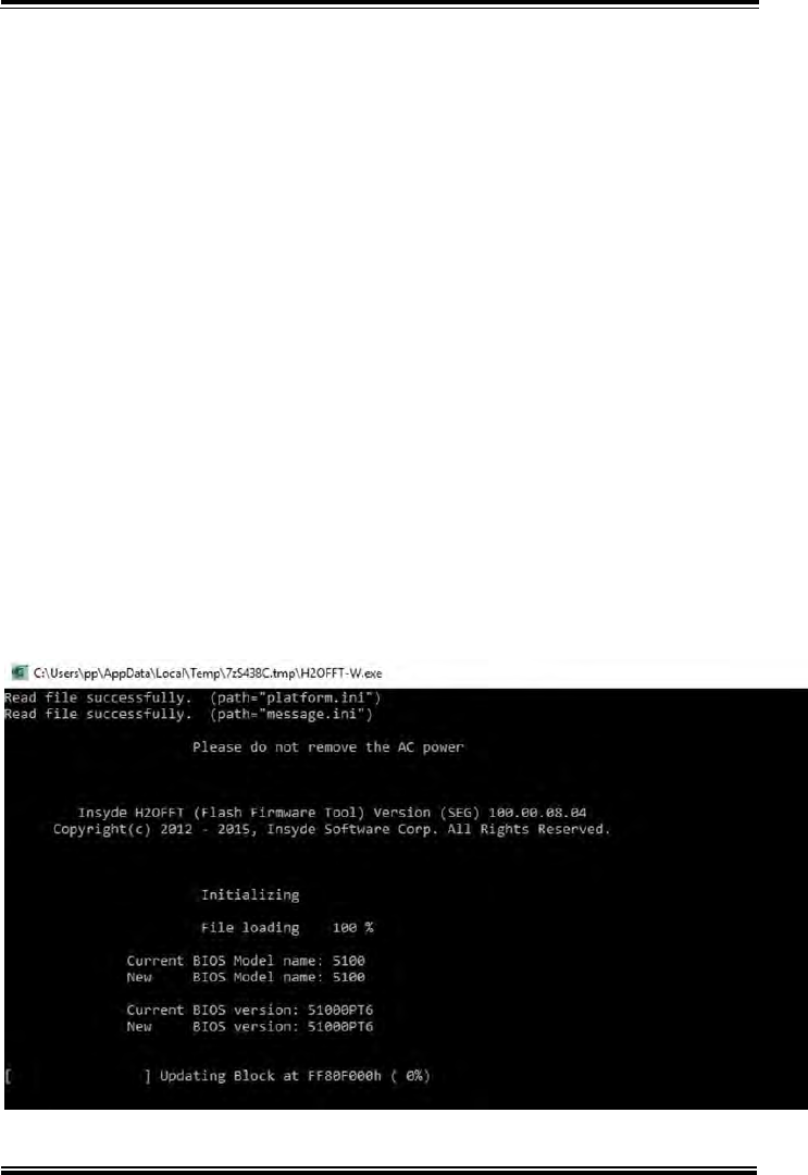
Appendix B Technical Summary
MH-5100 SERIES USER MANUAL
Page: B-20
System BIOS Update Procedure
System BIOS Update from O.S.
1 Prepare a bootable media (e.g. USB storage device) which can boot
the system to UEFI32 prompt.
2 Download and save the BIOS file (e.g. 51000PT6.exe) to the
bootable device.
3 Press the Power Button to boot up the system into the O.S. with
USB storage device (Windows 10 32 bits)
4 Run the BIOS file (e.g. 51000PT6.exe) in USB storage device on
O.S (Windows 10 32 bits)
5 During the update procedure, you will see the BIOS update process
status and its percentage. Beware! Do not turn off system power or
reset your computer if the whole update procedure is not complete
yet; otherwise, it may crash the BIOS ROM and the system will be
unable to boot up next time.
6 After the BIOS update procedure is completed, the following
message will be shown (e.g. Updating Block at FFFFFFFFh
(100%):