PORTMAN ELECTRONICS CTS-100XT Heavy Equipment Unit/Container Tracking User Manual
PORTMAN ELECTRONICS (DONGGUAN) CO., LTD. Heavy Equipment Unit/Container Tracking
UserManual.wiki
>
PORTMAN ELECTRONICS
>
CTS 100XT User Manual
Users manual
Navigation menu
Upload a User Manual
Namespaces
Wiki Guide
HTML
PDF
Info
Views
User Manual
Discussion / Help
Navigation
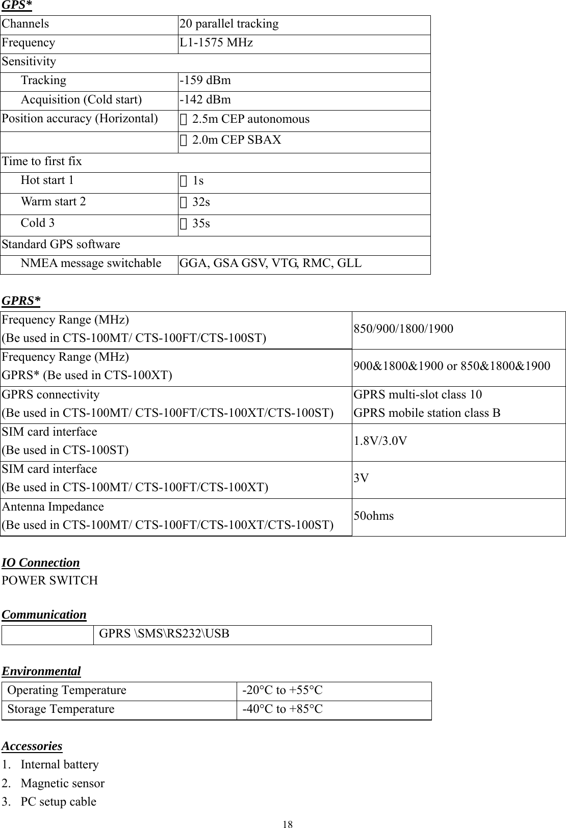
![9 B. Version No. Checking The below interface will last until correct UNIT Version No. is checked. (You should run this program before turn on power of UNIT) C. MAIN INTERFACE 1. [User detail]:](https://usermanual.wiki/PORTMAN-ELECTRONICS/CTS-100XT/User-Guide-1038984-Page-10.png)
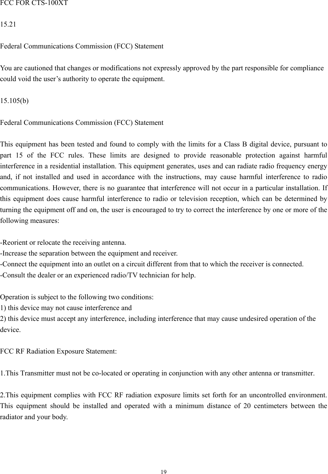
![12 2. [Geo-fence]: Setup the circular Geo-fence parameters in this window. The format will be center of the Geo-fence and the related radius.](https://usermanual.wiki/PORTMAN-ELECTRONICS/CTS-100XT/User-Guide-1038984-Page-13.png)
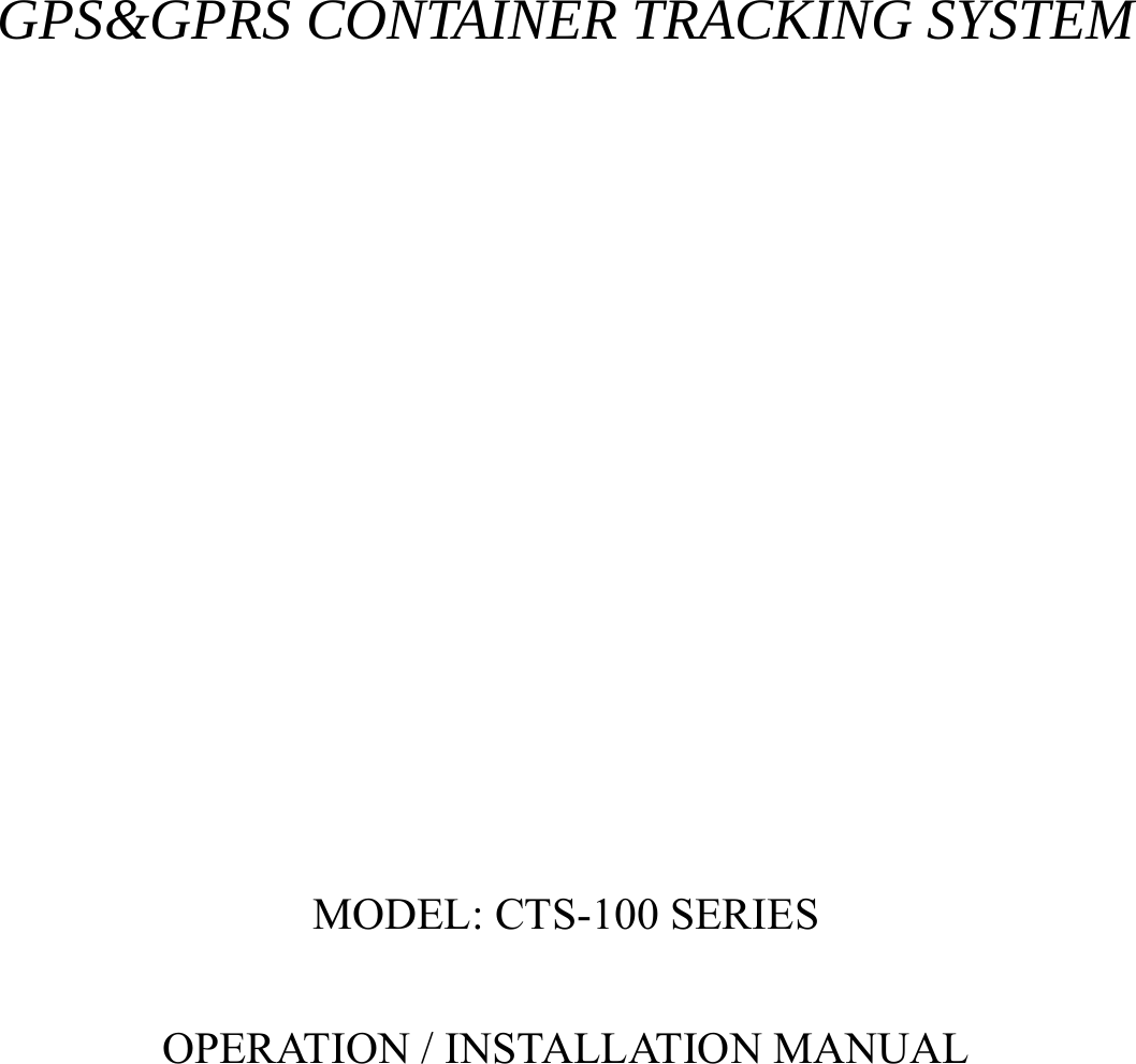
![13 3. [Report]: Report setup can be configured in this section. To activate the function(s), please select “√” in checkbox and fill in data in the textbox. There are 2 modes for the CTS-100, first is the Normal mode, and second is the Power saving mode. In normal mode, the GPS will be always activated if CTS-100 is in moving state. However, if in Power saving mode, CTS-100 will turn off the GPS power if there is no report to send. Note: that user can configure the wakeup report if the device is in “stop” (not moving) state. Normal mode, report will be summarized as: (1) Fixed time report Parameters: On/Off, and time. (2) Fixed distance report Parameters: On/Off, and distance. (min. distance is 0.1 km, max. distance is 100 km). (3) Speeding report: (min. speed is 0.1 km/Hr, max. speed is 1000 km/Hr). Parameters: on/off, and speed](https://usermanual.wiki/PORTMAN-ELECTRONICS/CTS-100XT/User-Guide-1038984-Page-14.png)
![16&&Y04,[connection time],[report interval]: For example: &&Y04,3600,60 When received this command, system will connect to server in the next 3600 seconds, and send one report out every 60 seconds. Low battery report: Low battery warning report (to alert user when the external battery level is low) Parameters: On/Off, and warning battery level for report. For example, 30 to represent 30% lower level report. The system will ignore the parameter with a value ‘0’ to prevent continuous non-stop reporting. Low battery, unit will cut power of GPS, only call function will be activated. Acceleration sensor: To determine whether CTS-100 is moving or not, user can select the sensitivity of the “acceleration sensor”. It is distinguished by the tilt angle of the device. If the unit tilted more than the degree set here, CTS-100 will be in moving mode. Otherwise, it will be in stop mode. The smaller the parameter of degree for the sensor set in pc-setup is, the higher the sensitivity is. Otherwise, the result is the opposite. You can select the Acceleration sensor trigger report to be sent or not, while the unit is moved. “Select” (by click), the related reports will be sent. Otherwise the report will be ignored, when the device is moved.](https://usermanual.wiki/PORTMAN-ELECTRONICS/CTS-100XT/User-Guide-1038984-Page-17.png)
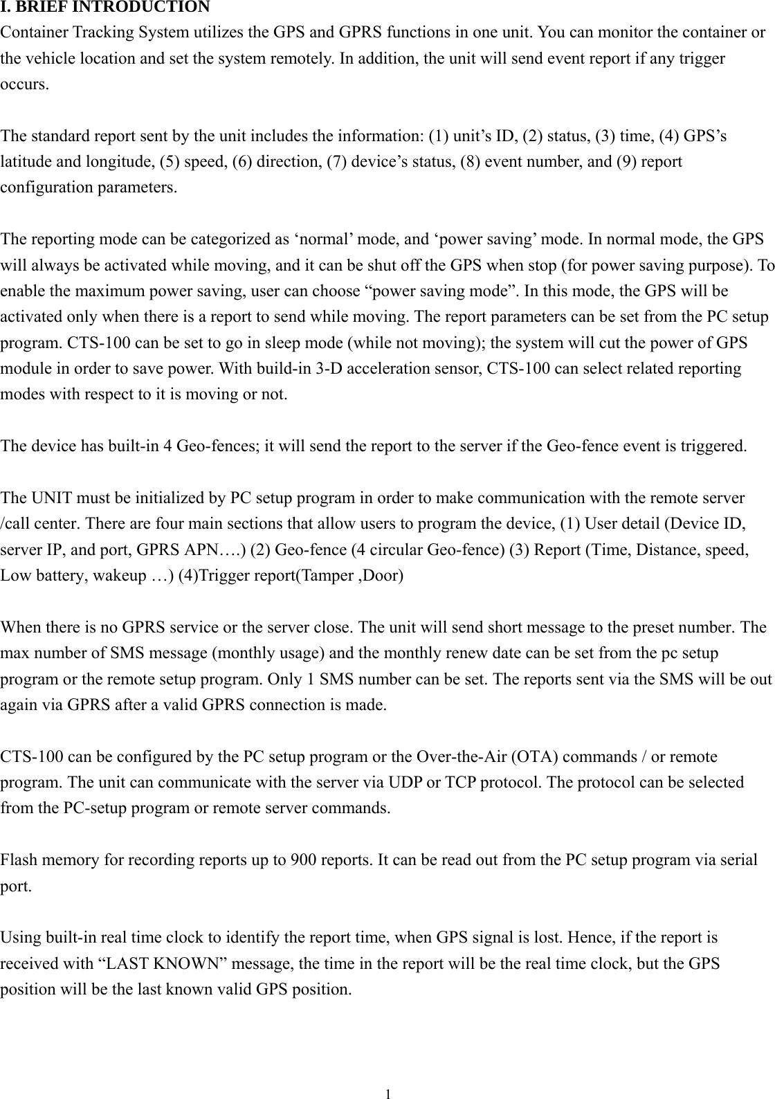
![17 4. [Trigger report setup] The unit has built-in door magnetic sensor and tamper switch, user can select if send report when the door sensor and tamper switch has triggered. 1.door sensor :It will send out event reports when door on or off. 2.Tamper switch: the tamper switch is used to check the box of host, when the box of host is moved over, it will send out a relevant report. CTS-100 SPECIFICATIONS Physical Parameters Enclosure dimensions (mm) 96(L)*50(W)*42(H) Unit Weight About 400g Electrical Operating current 52mA Voltage (Recharge) 5V-16V Current (Recharge) 770mA Current (sleep) 0.5-11.6mA Battery Battery type Battery capacity Charge type Battery Lithium 3.7V 3600mAh Built-in charge circuit](https://usermanual.wiki/PORTMAN-ELECTRONICS/CTS-100XT/User-Guide-1038984-Page-18.png)