PORTMAN ELECTRONICS GT-2000 Personal Tracking System User Manual GT2000 manuel
PORTMAN ELECTRONICS (DONGGUAN) CO., LTD. Personal Tracking System GT2000 manuel
UserManual.wiki
>
PORTMAN ELECTRONICS
>
GT 2000 User Manual
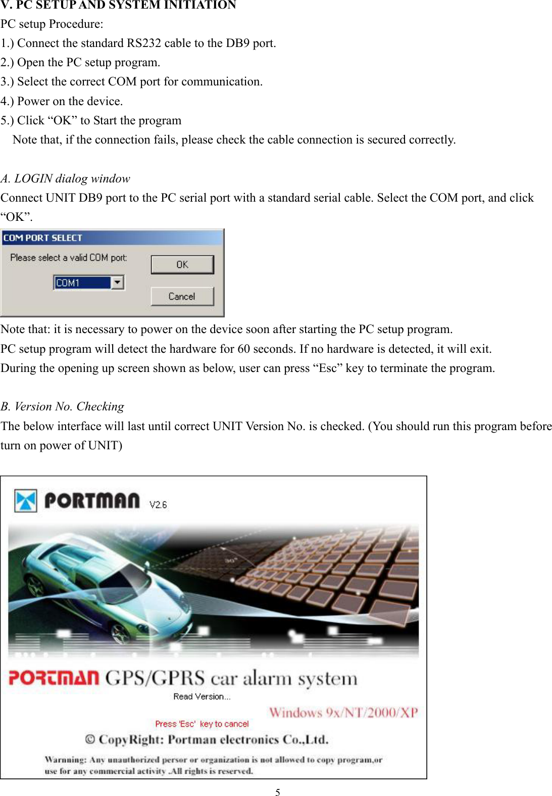
Users Manual
Navigation menu
Upload a User Manual
Namespaces
Wiki Guide
HTML
PDF
Info
Views
User Manual
Discussion / Help
Navigation
![6C. MAIN INTERFACE 1.[User detail]: If the SIM card is password protected, user can input the “SIM PIN” window to set password of SIM Card. Set UNIT ID and UNIT password of for the device. Set Access Point Name (APN), User Name, Password. The maximum length of the APN, User name and Password is 49 characters. TCP/UDP address and Port number of alarm center being set, UNIT will send message to these address. Note that either TCP or UDP should be selected. Note that: the IP address and port must input correctly, otherwise it will cause fail to make a call. UNIT can save 900 reports (900-1) recently; Click ‘Export’ button can export them with Excel or Text format.](https://usermanual.wiki/PORTMAN-ELECTRONICS/GT-2000/User-Guide-687540-Page-7.png)
![7 Set the primary SMS Number of the server. The unit will send reports to the server if GPRS connection is failed. Setup the max. number of the SMS can be sent out from the unit every month. By default, it will be renewed by the first date of every month. “Initialize ” button: clear all data in UNIT. Request All: read out the whole existing setting from GT8000/GT8500. Request: read out the setting in the current page. Apply: transfer the setting to GT8000/GT8500 in the current pages. Apply All: transfer the whole setting to GT8000/GT8500. Load: load the saved configuration files. Save: save the current configuration setting to a file. “Exit ” button: exit PC-Setup to main program. 2.[Geo-fence]: Setup the circular Geofence parameters in this window. The format will be center of the Geofence and the related radius.](https://usermanual.wiki/PORTMAN-ELECTRONICS/GT-2000/User-Guide-687540-Page-8.png)
![8 Here is the section to set the 3 telephone numbers for speed dialing. Please refer to speed dialing button operation. 3.[Report]: Report setup can be configured in this section. To activate the function(s), please select “√” in checkbox and fill in data in the textbox. There are 2 modes for the GT-2000, first is the Normal mode, and second is the Power saving mode. In the normal mode, the GPS will be always activated if GT-2000 is in moving state. However, if in Power saving mode, GT-2000 will turn off the GPS power if there is no report to send. Note that user can configure the wakeup report if the device is in “stop” (not moving) state. Normal mode, report will be summarized as: (1) Fixed time report Parameters: On/Off, and time. (2) Fixed distance report Parameters: On/Off, and distance. (min. distance is 0.1 km, max. distance is 100 km). (3)Keep alive report Parameters: On/Off, and interval time, retry times Keep alive enable, system will send out keep alive information to server and wait acknowledge from server. If within the certain request period, there is no acknowledge back, the system will close the connection and will establish a new connection. The parameters includes the keep alive “interval”, and within this interval the retry “times”.](https://usermanual.wiki/PORTMAN-ELECTRONICS/GT-2000/User-Guide-687540-Page-9.png)
![9Emergency request report: If the user does not set the keep alive, GT-2000 might lose the GPRS connection (if it is been cut by the Network). The system will not actively re-connect to server, it will wait for a new trigger (or report) and then start the connection / then send to the server. Special command for SMS mode: If the GT-2000 is not in the GPRS online status, user can send command &&Y02 or &&Y04 to ask unit to connect to server. This command can be sent from any device via SMS; &&Y02: When received this command, system will actively try to connect to server in next 600 seconds. &&Y04,[connection time],[report interval]: For example: &&Y04,3600,60 When received this command, system will connect to server in the next 3600 seconds, and send one report out every 60 seconds. (3)GPS wakeup report: While the device is in stop status, user can let the GPS go to sleep mode for power saving. If select GPS Sleep ON, user can setup the wakeup report configuration/ or NO GPS wakeup report. IF select GPS Sleep OFF, GT-2000 will follow the report sending rule in “When Moving” section. Power saving mode While in Power saving mode, GT-2000 will cut off the GPS power if there is no report to send. Report configuration will be listed as: the fixed time report while moving, and wakeup report / or no GPS wakeup report while stop. In this mode, in order to save power unit will cut power of GPS, only wake up GPS at the time of send report. Low battery report: Low battery warning report (to alert user when the external battery level is low) Parameters: On/Off, and warning battery level for report. For example, 30 to represent 30% lower level report. The system will ignore the parameter with a value ‘0’ to prevent continuous non-stop reporting. Low battery, unit will cut power of GPS, only call function will be activated. Acceleration sensor:](https://usermanual.wiki/PORTMAN-ELECTRONICS/GT-2000/User-Guide-687540-Page-10.png)