PORTMAN ELECTRONICS GT-2000NP PERSONAL TRACKING SYSTEM User Manual
PORTMAN ELECTRONICS (DONGGUAN) CO., LTD. PERSONAL TRACKING SYSTEM
UserManual.wiki
>
PORTMAN ELECTRONICS
>
GT 2000NP User Manual
USERS MANUAL
Navigation menu
Upload a User Manual
Namespaces
Wiki Guide
HTML
PDF
Info
Views
User Manual
Discussion / Help
Navigation
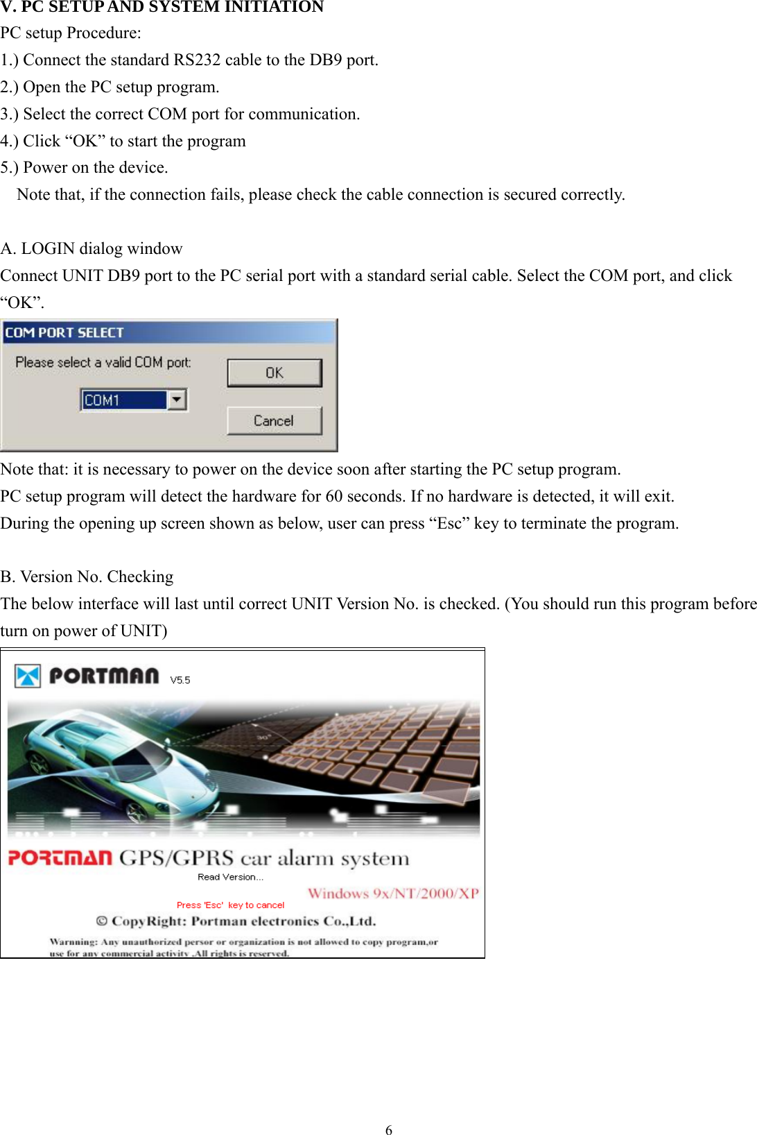
![7C. MAIN INTERFACE 1. [User detail]: If the SIM card is password protected, user can input the “SIM PIN” window to set password of SIM Card. Set UNIT ID and UNIT password of for the device. Set Access Point Name (APN), User Name, Password. The maximum length of the APN, User name and Password is 49 characters. TCP/UDP address and Port number of alarm center being set, UNIT will send message to these address. Note that either TCP or UDP should be selected. Note: the IP address and port must input correctly, otherwise it will cause fail to make a call.](https://usermanual.wiki/PORTMAN-ELECTRONICS/GT-2000NP/User-Guide-874770-Page-8.png)
![8 UNIT can save 900 reports (900-1). Click ‘Export’ button can export them with Excel or Text format. Set the primary SMS Number of the server. The unit will send reports to the server if GPRS connection is failed. Setup the max number of the SMS can be sent out from the unit every month. By default, it will be renewed by the first date of every month. “Initialize” button: clear all data in UNIT. Request All: read out the whole existing setting from GT2000NP/GT2500NP Request: read out the setting in the current page. Apply: transfer the setting to GT2000NP/GT2500NP in the current pages. Apply All: transfer the whole setting to GT2000NP/GT2500NP. Load: load the saved configuration files. Save: save the current configuration setting to a file. “Exit” button: exit PC-Setup to main program. 2. [Geo-fence]: Setup the circular Geofence parameters in this window. The format will be center of the Geofence and the related radius.](https://usermanual.wiki/PORTMAN-ELECTRONICS/GT-2000NP/User-Guide-874770-Page-9.png)
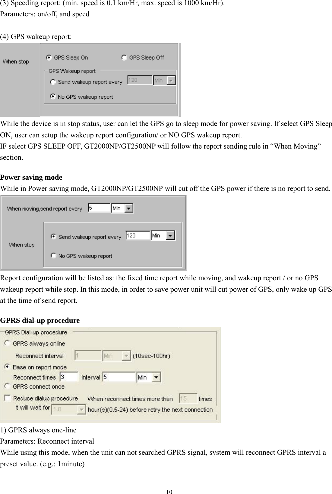
![9 Here is the section to set the 3 telephone numbers for speed dialing. Please refer to speed dialing button operation. 3. [Report]: Report setup can be configured in this section. To activate the function(s), please select “√” in checkbox and fill in data in the textbox. There are 2 modes for the GT2000NP/GT2500NP, first is the Normal mode, and second is the Power saving mode. In normal mode, the GPS will be always activated if GT2000NP/GT2500NP is in moving state. However, if in Power saving mode, GT2000NP/GT2500NP will turn off the GPS power if there is no report to send. Note: that user can configure the wakeup report if the device is in “stop” (not moving) state. Normal mode, report will be summarized as: (1) Fixed time report Parameters: On/Off, and time. (2) Fixed distance report Parameters: On/Off, and distance. (min. distance is 0.1 km, max. distance is 100 km).](https://usermanual.wiki/PORTMAN-ELECTRONICS/GT-2000NP/User-Guide-874770-Page-10.png)
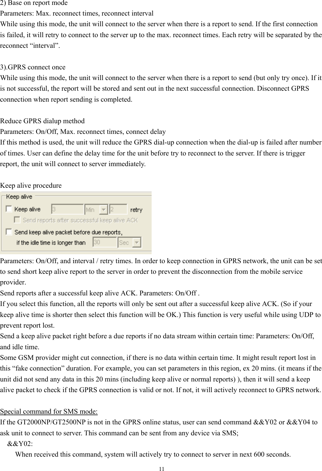
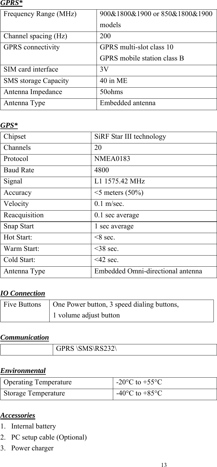
![12&&Y04,[connection time],[report interval]: For example: &&Y04,3600,60 When received this command, system will connect to server in the next 3600 seconds, and send one report out every 60 seconds. Low battery report: Low battery warning report (to alert user when the external battery level is low) Parameters: On/Off, and warning battery level for report. For example, 30 to represent 30% lower level report. The system will ignore the parameter with a value ‘0’ to prevent continuous non-stop reporting. Low battery, unit will cut power of GPS, only call function will be activated. Acceleration sensor: To determine whether GT2000NP/GT2500NP is moving or not, user can select the sensitivity of the “acceleration sensor”. It is distinguished by the tilt angle of the device. If the unit tilted more than the degree set here, GT2000NP/GT2500NP will be in moving mode. Otherwise, it will be in stop mode. The smaller the parameter of degree for the sensor set in pc-setup is, the higher the sensitivity is, otherwise, the result is the opposite. You can select the Acceleration sensor trigger report to be sent or not, while the unit is moved. “Select” (by click), the related reports will be sent. Otherwise the report will be ignored, when the device is moved. APPENDIX 1 GT2000NP/GT2500NP SPECIFICATIONS Physical Parameters Enclosure dimensions (mm) 95(L)*47(W)*20 (H) Weight 100g Electrical DC Supply voltage 3.6V Recharge voltage 5V-20V Current (GPRS online) 80mA Current (GPRS transmission) 120mA Current (Peak) 300mA Current (Sleep) 6~12mA (when GPS is in sleep mode) Battery Battery type Battery capacity Charge type Battery Lithium 3.6V 1700mAh/1050mAh Built-in charge circuit](https://usermanual.wiki/PORTMAN-ELECTRONICS/GT-2000NP/User-Guide-874770-Page-13.png)