PORTMAN ELECTRONICS GT-2000NP PERSONAL TRACKING SYSTEM User Manual
PORTMAN ELECTRONICS (DONGGUAN) CO., LTD. PERSONAL TRACKING SYSTEM
USERS MANUAL

OPERATION MANUAL
GPS&GPRS PERSONAL TRACKING
GT2000NP/GT2500NP
1
GT2000NP REV 3.1 (GT2000NP gt2k4-d-ptm-5.5.2-2.03.enc gt2000np-d3)
I. BRIEF INTRODUCTION
Personal Tracking System utilizes the GPS and GPRS functions in one unit. You can monitor the vehicle or the
people location and set the system remotely. In addition, the unit will send event report if any trigger occurs.
The standard report sent by the unit includes the information: (1) unit’s ID, (2) status, (3) time, (4) GPS’s
latitude and longitude, (5) speed, (6) direction, (7) device’s status, (8) event number, and (9) report
configuration parameters.
The reporting mode can be categorized as ‘normal’ mode, and ‘power saving’ mode. In normal mode, the GPS
will always be activated while moving, and it can be shut off the GPS when stop (for power saving purpose). To
enable the maximum power saving, user can choose “power saving mode”. In this mode, the GPS will be
activated only when there is a report to send while moving. The report parameters can be set from the PC setup
program. GT2000NP/GT2500NP can be set to go in sleep mode (while not moving), the system will cut the
power of GPS module in order to save power. With build-in 3-D acceleration sensor, GT2000NP/GT2500NP
can select related reporting modes with respect to it is moving or not.
The device has built-in 4 Geo-fences and one immediate Geo-fence (in circular shapes), it will send the report
to the server if the Geofence event is triggered.
The UNIT must be initialized by PC setup program in order to make communication with the remote server
/call center. There are three main sections that allow users to program the device, (1) User detail (Device ID,
server IP, and port, GPRS APN….) (2) Geo-fence (5 circular Geo-fence) (3) Report (Time, Distance, speed,
Low battery, wakeup …)
A unique help report: user can press the Button 3 for 2 seconds after the unit power on. The unit will send the
help report to server, power LED flash 5 times at the same time.
Taxi mode on/off: Pressing “II” twice within 2 seconds will put the unit into “Taxi mode”. Pressing “II” twice
again within 2 seconds will take the unit out of “Taxi mode”. When the unit enters “Taxi mode”, the top LED
will flash 3 times/3sec and unit will vibrate once every minute. When in Taxi mode, the unit will automatically
vibrate every one minute. When the unit vibrates at these intervals, the user must press “II” within one minute
each time, if not, the unit will automatically send an “SOS” report to the server.
When there is no GPRS service or the server close. The unit will send short message to the preset number. The
max number of SMS message (monthly usage) and the monthly renew date can be set from the pc setup
program or the remote setup program. Only 1 SMS number can be set. The reports sent via the SMS will be out
again via GPRS after a valid GPRS connection is made.
GT2000NP/GT2500NP can be configured by the PC setup program or the Over-the-Air (OTA) commands / or
remote program. The unit can communicate with the server via UDP or TCP protocol. The protocol can be
selected from the PC-setup program or remote server commands.

2
Flash memory for recording reports up to 900 reports. It can be read out from the PC setup program via serial
port.
On the left side, there are two buttons (‘+”button and ‘-”button) used to change the ring volume. Push ‘+”button
for 2sec. to select Vibration, ring or ring & vibration together modes.
Recharge battery need three hours, after finish recharging, Power LED will change to green.
Call Monitoring: user can send a SMS that included the preset password of the unit. GT2000NP/GT2500NP
will send “PASS” SMS ACK back, unit will auto answer the phone in the following 10 minutes.
Using built-in real time clock to identify the report time, when GPS signal is lost. Hence, if the report is
received with “LAST KNOWN” message, the time in the report will be the real time clock, but the GPS
position will be the last known valid GPS position.
Three LED indicate the status of the SYSTEM, GPRS signal and GPS signal.
SYSTEM LED: to refer the IV. BUTTON OPERATION
YELLOW LED: GSM/GPRS indicator. Yellow LED will flash when the device is connected to the server with
valid GPRS connection. It will stay continuously on when it is in GSM mode. It will stay off if there is no GSM
reception.
GPS indicator (bottom LED): LED is GREEN when the unit has acquired a valid GPS signal, and it will flash
when the unit is searching GPS signal.
Note that the GREEN LED’s indication will not be valid until the system goes to the working mode, normally
30 seconds after power on.
II. BASIC FUNCTIONS
FUNCTIONS APPLICATIONS
GPS GPS receiver will output a complete position, velocity, and time (PVT) solution in the
NMEA Version 3.0 protocol
GPRS, SMS GPRS use standard TCP or UDP communicate protocol. If the GPRS service is failed,
the SMS mode will be turned on for emergency use.
Button
Power button
Three Buttons for call, Help, SOS….(right side)
Two buttons control volume of ring and sound. (left side)
PC-setup
Initialize the unit and program the device, including Network APN, server IP address,
user message, report control, and Geo-fence setting, etc …
Note that Network APN and server IP details must be set before the installation.
Standard Report
Automatic report for tracking purpose:
Fixed time report
Fixed distance report
Speeding report
History data store 900 report can be saved in unit and read from server and pc-setup
3
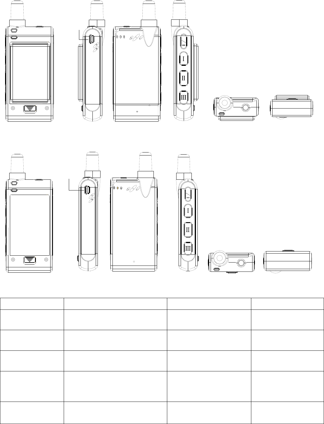
III. PANEL INSTALLATION
(1): Unit with 1700mAh battery
PC-SETUP
+
(2): Unit with 1050mAh battery
PC-SETUP
+
IV. BUTTON OPERATION:
Button Indication Functions Conditions
Press power switch
button once Power LED flash 1time/3sec. Power ON Power off
Power LED normal is green, if low
power then change to red Low power
Press power switch
button for 3sec. Power LED off Power OFF Power on
If charging then power LED is red,
if charge ok then power LED
change to green.
Charging
Press button1 once Power LED change to orange Answer the coming call. When an incoming call
is received

4
Power LED flash 2time/3sec.
When a self-geo-fence is set, the
unit will chirp twice
Self-Geo-fence ON
No incoming call is
received and
self-Geofence off
Press button1 once
Power LED restore normal Self-Geofence OFF
No incoming call is
received and
self-Geofence on
Press button1 for
2sec.
Power LED flash quickly 3 times
then restore normal
If there is a GPS signal when an
“SOS” report is sent, the unit will
vibrate once. If there is no GPS
signal when an “SOS” report is
sent, the unit will vibrate twice.
When SOS reports sent, the GPS
module powers off and resets
again, the GPS signal detected, the
unit will be sent “123” report.
Send SOS report No incoming call is
received
Press button2 once Power LED restore normal Hang up the call.
When a call come or in
communication or
Dialing out
When the unit enters “Taxi mode”,
the Power LED will flash 3
times/3sec and unit will vibrate
once every minute.
Put the unit into “Taxi
mode”. When in Taxi mode,
the unit will automatically
vibrate every one minute.
When the unit vibrates at
these intervals, the user
must press button2 within
one minute each time, if not,
the unit will automatically
send an “SOS” report to the
server.
No incoming call is
received and no in “Taxi
mode”
Press button2 twice
within 2 seconds
Power LED restore normal Take the unit out of “Taxi
mode”.
No incoming call is
received and in Taxi
mode
Press button2 for
2sec.
Power LED flash 2 times orange
and 1 time green(if low power
then red) every 3sec.
If there is a GPS signal when an
“SOS” report is sent, the unit will
vibrate once. If there is no GPS
signal when an “SOS” report is
sent, the unit will vibrate twice.
Send SOS report and into
monitor mode.
No incoming call is
received no in monitor
mode

5
Power LED restore normal Exit monitor mode
No incoming call is
received in monitor
mode
Power LED flash quickly 5 times
then restore normal. When a “help”
report is sent, the unit will chirp
three times
Send help report No incoming call is
received
Press button3 for
2sec.
Power LED change to orange and
flash quickly. When a call come or
Dialing out
Press button3 once
then press button1
once within 2sec.
Power LED change to orange and
flash quickly. When dialing out,
the unit will chirp once
If dialing out to a number fails, the
unit will chirp twice.
Auto dialing out the first
telephone No. of preset by
PC-setup.
No incoming call is
received
Press button3 once
then press button2
once within 2sec.
Power LED change to orange and
flash quickly. When dialing out,
the unit will chirp once
If dialing out to a number fails, the
unit will chirp twice.
Auto dialing out the second
telephone No. of preset by
PC-setup.
No incoming call is
received
Press button3 once
then press button3
once within 2sec.
Power LED change to orange and
flash quickly. When dialing out,
the unit will chirp once
If dialing out to a number fails, the
unit will chirp twice.
Auto dialing out the third
telephone No. of preset by
PC-setup.
No incoming call is
received
Press button“-”once As normal Ring or sound become low If speaking, change
sound
Press button ‘+” once As normal Ring or sound become high If speaking, change
sound
Press button “-” for
2sec. As normal Selection different sounds,
there are six kinds of sound.
Press button ‘+” for
2sec. As normal
Change to vibrate, ring or
ring + vibrate together
modes
Power LED indication priority:
1、call coming or communication or Dialing out
2、SOS report
3、help report
4、monitor mode
5、Self-Geofence
6、Taxi mode
7、charging
8、power on/off and low power

6
V. PC SETUP AND SYSTEM INITIATION
PC setup Procedure:
1.) Connect the standard RS232 cable to the DB9 port.
2.) Open the PC setup program.
3.) Select the correct COM port for communication.
4.) Click “OK” to start the program
5.) Power on the device.
Note that, if the connection fails, please check the cable connection is secured correctly.
A. LOGIN dialog window
Connect UNIT DB9 port to the PC serial port with a standard serial cable. Select the COM port, and click
“OK”.
Note that: it is necessary to power on the device soon after starting the PC setup program.
PC setup program will detect the hardware for 60 seconds. If no hardware is detected, it will exit.
During the opening up screen shown as below, user can press “Esc” key to terminate the program.
B. Version No. Checking
The below interface will last until correct UNIT Version No. is checked. (You should run this program before
turn on power of UNIT)
7
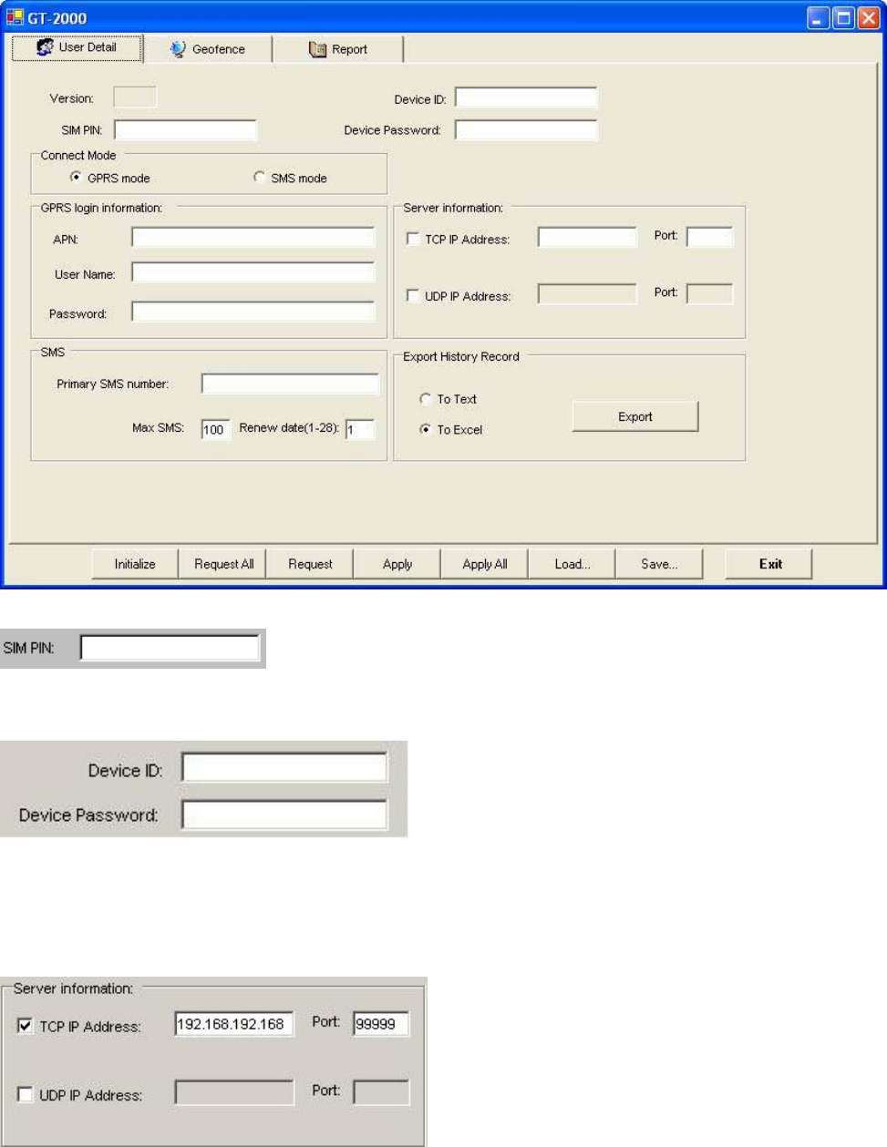
C. MAIN INTERFACE
1. [User detail]:
If the SIM card is password protected, user can input the “SIM PIN” window to set password of SIM Card.
Set UNIT ID and UNIT password of for the device.
Set Access Point Name (APN), User Name, Password. The maximum length of the APN, User name and
Password is 49 characters.
TCP/UDP address and Port number of alarm center being set, UNIT will send message to these address.
Note that either TCP or UDP should be selected.
Note: the IP address and port must input correctly, otherwise it will cause fail to make a call.
8
UNIT can save 900 reports (900-1). Click ‘Export’ button can export them with Excel or Text format.
Set the primary SMS Number of the server. The unit will send reports to the server if GPRS connection is
failed.
Setup the max number of the SMS can be sent out from the unit every month. By default, it will be renewed by
the first date of every month.
“Initialize” button: clear all data in UNIT.
Request All: read out the whole existing setting from GT2000NP/GT2500NP
Request: read out the setting in the current page.
Apply: transfer the setting to GT2000NP/GT2500NP in the current pages.
Apply All: transfer the whole setting to GT2000NP/GT2500NP.
Load: load the saved configuration files.
Save: save the current configuration setting to a file.
“Exit” button: exit PC-Setup to main program.
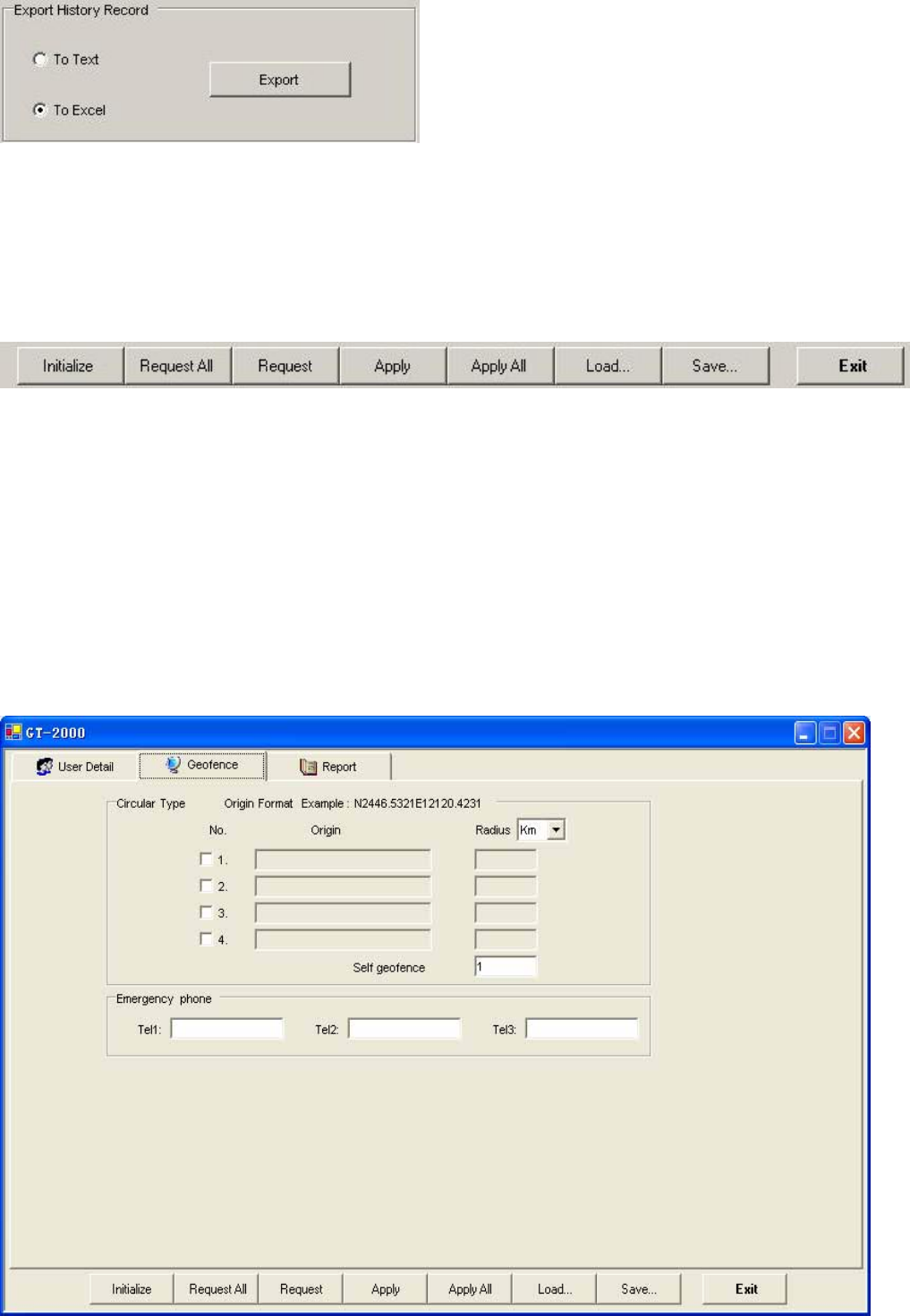
2. [Geo-fence]:
Setup the circular Geofence parameters in this window. The format will be center of the Geofence and the
related radius.
9
Here is the section to set the 3 telephone numbers for speed dialing. Please refer to speed dialing button
operation.
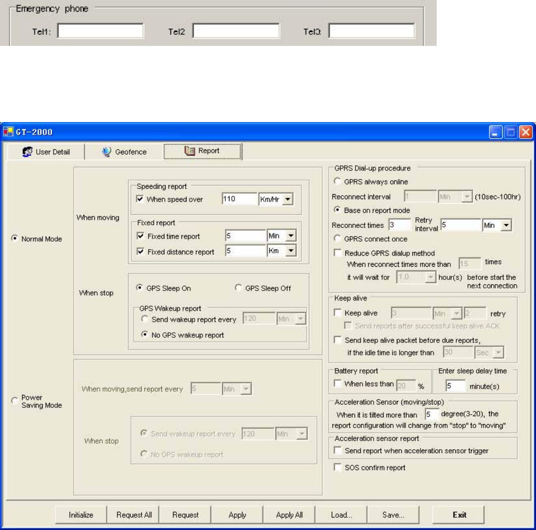
3. [Report]:
Report setup can be configured in this section. To activate the function(s), please select “√” in checkbox and fill
in data in the textbox. There are 2 modes for the GT2000NP/GT2500NP, first is the Normal mode, and second
is the Power saving mode. In normal mode, the GPS will be always activated if GT2000NP/GT2500NP is in
moving state. However, if in Power saving mode, GT2000NP/GT2500NP will turn off the GPS power if there
is no report to send.
Note: that user can configure the wakeup report if the device is in “stop” (not moving) state.
Normal mode, report will be summarized as:
(1) Fixed time report
Parameters: On/Off, and time.
(2) Fixed distance report
Parameters: On/Off, and distance. (min. distance is 0.1 km, max. distance is 100 km).
10
(3) Speeding report: (min. speed is 0.1 km/Hr, max. speed is 1000 km/Hr).
Parameters: on/off, and speed
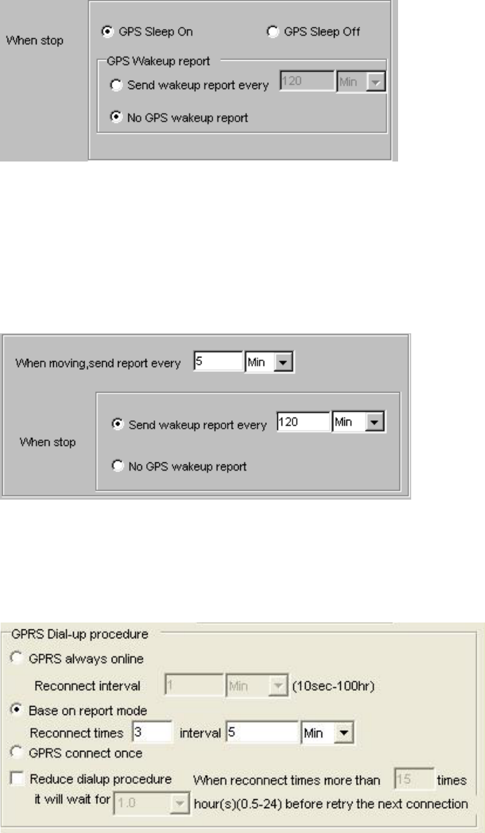
(4) GPS wakeup report:
While the device is in stop status, user can let the GPS go to sleep mode for power saving. If select GPS Sleep
ON, user can setup the wakeup report configuration/ or NO GPS wakeup report.
IF select GPS SLEEP OFF, GT2000NP/GT2500NP will follow the report sending rule in “When Moving”
section.
Power saving mode
While in Power saving mode, GT2000NP/GT2500NP will cut off the GPS power if there is no report to send.
Report configuration will be listed as: the fixed time report while moving, and wakeup report / or no GPS
wakeup report while stop. In this mode, in order to save power unit will cut power of GPS, only wake up GPS
at the time of send report.
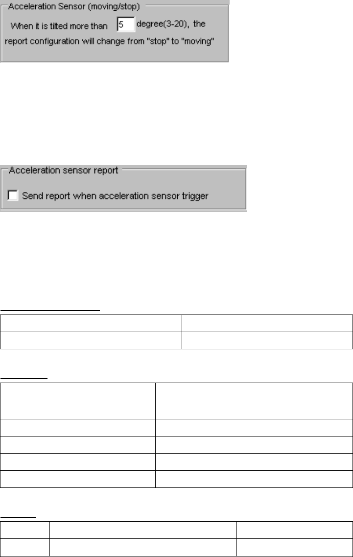
GPRS dial-up procedure
1) GPRS always one-line
Parameters: Reconnect interval
While using this mode, when the unit can not searched GPRS signal, system will reconnect GPRS interval a
preset value. (e.g.: 1minute)

11
2) Base on report mode
Parameters: Max. reconnect times, reconnect interval
While using this mode, the unit will connect to the server when there is a report to send. If the first connection
is failed, it will retry to connect to the server up to the max. reconnect times. Each retry will be separated by the
reconnect “interval”.
3).GPRS connect once
While using this mode, the unit will connect to the server when there is a report to send (but only try once). If it
is not successful, the report will be stored and sent out in the next successful connection. Disconnect GPRS
connection when report sending is completed.
Reduce GPRS dialup method
Parameters: On/Off, Max. reconnect times, connect delay
If this method is used, the unit will reduce the GPRS dial-up connection when the dial-up is failed after number
of times. User can define the delay time for the unit before try to reconnect to the server. If there is trigger
report, the unit will connect to server immediately.
Keep alive procedure
Parameters: On/Off, and interval / retry times. In order to keep connection in GPRS network, the unit can be set
to send short keep alive report to the server in order to prevent the disconnection from the mobile service
provider.
Send reports after a successful keep alive ACK. Parameters: On/Off .
If you select this function, all the reports will only be sent out after a successful keep alive ACK. (So if your
keep alive time is shorter then select this function will be OK.) This function is very useful while using UDP to
prevent report lost.
Send a keep alive packet right before a due reports if no data stream within certain time: Parameters: On/Off,
and idle time.
Some GSM provider might cut connection, if there is no data within certain time. It might result report lost in
this “fake connection” duration. For example, you can set parameters in this region, ex 20 mins. (it means if the
unit did not send any data in this 20 mins (including keep alive or normal reports) ), then it will send a keep
alive packet to check if the GPRS connection is valid or not. If not, it will actively reconnect to GPRS network.
Special command for SMS mode:
If the GT2000NP/GT2500NP is not in the GPRS online status, user can send command &&Y02 or &&Y04 to
ask unit to connect to server. This command can be sent from any device via SMS;
&&Y02:
When received this command, system will actively try to connect to server in next 600 seconds.
12
&&Y04,[connection time],[report interval]:
For example: &&Y04,3600,60
When received this command, system will connect to server in the next 3600 seconds, and send one report
out every 60 seconds.
Low battery report:
Low battery warning report (to alert user when the external battery level is low)
Parameters: On/Off, and warning battery level for report. For example, 30 to represent 30% lower level report.
The system will ignore the parameter with a value ‘0’ to prevent continuous non-stop reporting. Low battery,
unit will cut power of GPS, only call function will be activated.
Acceleration sensor:
To determine whether GT2000NP/GT2500NP is moving or not, user can select the sensitivity of the
“acceleration sensor”. It is distinguished by the tilt angle of the device. If the unit tilted more than the degree set
here, GT2000NP/GT2500NP will be in moving mode. Otherwise, it will be in stop mode. The smaller the
parameter of degree for the sensor set in pc-setup is, the higher the sensitivity is, otherwise, the result is the
opposite.
You can select the Acceleration sensor trigger report to be sent or not, while the unit is moved. “Select” (by
click), the related reports will be sent. Otherwise the report will be ignored, when the device is moved.
APPENDIX 1
GT2000NP/GT2500NP SPECIFICATIONS
Physical Parameters
Enclosure dimensions (mm) 95(L)*47(W)*20 (H)
Weight 100g
Electrical
DC Supply voltage 3.6V
Recharge voltage 5V-20V
Current (GPRS online) 80mA
Current (GPRS transmission) 120mA
Current (Peak) 300mA
Current (Sleep) 6~12mA (when GPS is in sleep mode)
Battery
Battery type Battery capacity Charge type
Battery Lithium 3.6V 1700mAh/1050mAh Built-in charge circuit

13
GPRS*
Frequency Range (MHz) 900&1800&1900 or 850&1800&1900
models
Channel spacing (Hz) 200
GPRS connectivity GPRS multi-slot class 10
GPRS mobile station class B
SIM card interface 3V
SMS storage Capacity 40 in ME
Antenna Impedance 50ohms
Antenna Type Embedded antenna
GPS*
Chipset SiRF Star III technology
Channels 20
Protocol NMEA0183
Baud Rate 4800
Signal L1 1575.42 MHz
Accuracy <5 meters (50%)
Velocity 0.1 m/sec.
Reacquisition 0.1 sec average
Snap Start 1 sec average
Hot Start: <8 sec.
Warm Start: <38 sec.
Cold Start: <42 sec.
Antenna Type Embedded Omni-directional antenna
IO Connection
Five Buttons One Power button, 3 speed dialing buttons,
1 volume adjust button
Communication
GPRS \SMS\RS232\
Environmental
Operating Temperature -20°C to +55°C
Storage Temperature -40°C to +85°C
Accessories
1. Internal battery
2. PC setup cable (Optional)
3. Power charger
14
VI. Federal Communications Commission (FCC) Statement
1)
You are cautioned that changes or modifications not expressly approved by the part responsible for compliance
could void the user’s authority to operate the equipment.
2)
This equipment has been tested and found to comply with the limits for a Class B digital device, pursuant to
part 15 of the FCC rules. These limits are designed to provide reasonable protection against harmful
interference in a residential installation. This equipment generates, uses and can radiate radio frequency energy
and, if not installed and used in accordance with the instructions, may cause harmful interference to radio
communications. However, there is no guarantee that interference will not occur in a particular installation. If
this equipment does cause harmful interference to radio or television reception, which can be determined by
turning the equipment off and on, the user is encouraged to try to correct the interference by one or more of the
following measures:
-Reorient or relocate the receiving antenna.
-Increase the separation between the equipment and receiver.
-Connect the equipment into an outlet on a circuit different from that to which the receiver is connected.
-Consult the dealer or an experienced radio/TV technician for help.
You are cautioned that changes or modifications not expressly approved by the party responsible for
compliance could void your authority to operate the equipment.
VII Operation is subject to the following two conditions:
1) this device may not cause interference and
2) this device must accept any interference, including interference that may cause undesired operation of the
device.
VIII FCC RF Radiation Exposure Statement:
1) This Transmitter must not be co-located or operating in conjunction with any other antenna or transmitter.
2) For body worn operation, this phone has been tested and meets FCC RF exposure guidelines when used with
an accessory that contains no metal and that positions the handset a minimum of 1.5 cm from the body. Use of
other accessories may not ensure compliance with FCC RF exposure guidelines."