PORTMAN ELECTRONICS GT3000U-X4 GPS Tracker User Manual
PORTMAN ELECTRONICS (DONGGUAN) CO., LTD. GPS Tracker Users Manual
UserManual.wiki
>
PORTMAN ELECTRONICS
>
GT3000U X4 User Manual
Users Manual
Navigation menu
Upload a User Manual
Namespaces
Wiki Guide
HTML
PDF
Info
Views
User Manual
Discussion / Help
Navigation
![7A. LOGIN DIALOG WINDOW Select the correct COM port number, then “reset” the unit by pressing the reset button, and next click “OK”. Note that: it is necessary to power on and reset the device soon after click the “ok” button. PC setup program will detect the hardware for 60 seconds. If no hardware is detected, it will exit. During the opening up screen shown as below, user can press “Esc” key to terminate the program. B. VERSION NO. CHECKING The below interface will last until correct UNIT Version No. is checked. (You should run this program before turn on power of UNIT) C. MAIN INTERFACE 1. [USER DETAIL:]](https://usermanual.wiki/PORTMAN-ELECTRONICS/GT3000U-X4/User-Guide-1560805-Page-8.png)
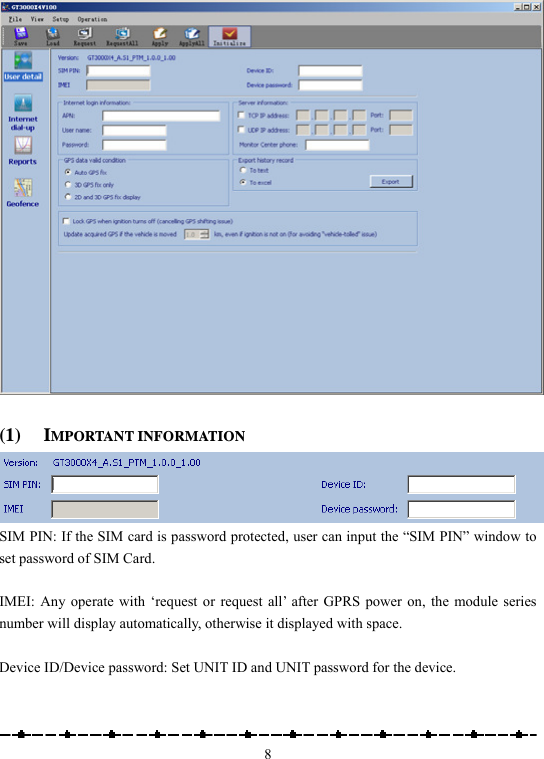
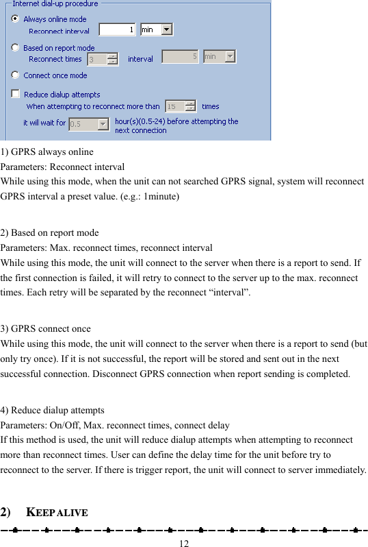
![11Apply All: transfer the whole setting to GT3000X4. Initialize: clear all data in UNIT. Note that Device ID, GPRS Login and server IP/Port information need to be input correctly in order to make the connection. If the report sending using GPRS connection fails, the report will be sent to the ‘primary’ SMS number first. The report will be resent, when the GPRS connection becomes available. 2. [INTERNET DIAL-UP:] 1) INTERNET DIAL-UP PROCEDURE](https://usermanual.wiki/PORTMAN-ELECTRONICS/GT3000U-X4/User-Guide-1560805-Page-12.png)
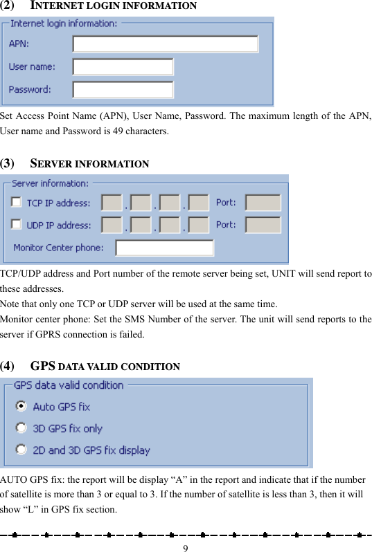
![13 Parameters: On/Off, and interval / retry times. In order to keep connection in GPRS network, the unit can be set to send short keep alive report to the server in order to prevent the disconnection from the mobile service provider. Send reports after a successful keep alive ACK. Parameters: On/Off. If you select this function, all the reports will only be sent out after a successful keep alive ACK. (So if your keep alive time is shorter then select this function will be OK.) This function is very useful while using UDP to prevent report lost. Send a keep alive packet right before due reports if no data stream within certain time: Parameters: On/Off and idle time. Some GSM provider might cut connection, if there is no data within certain time. It might result report lost in this “fake connection” duration. For example, you can set parameters in this region, ex 20 mins. (It means if the unit did not send any data in this 20 mins (including keep alive or normal reports), then it will send a keep alive packet to check if the GPRS connection is valid or not. If not, it will actively reconnect to GPRS network. Special command for SMS mode: If the GT3600 is not in the GPRS online status, user can send command &&Y02 or &&Y04 to ask unit to connect to server. This command can be sent from any device via SMS; &&Y02: When received this command, system will actively try to connect to server in next 600 seconds. &&Y04,[connection time],[report interval]: For example: &&Y04, 3600, 60 When received this command, system will connect to server in the next 3600 seconds, and send one report out every 60 seconds.](https://usermanual.wiki/PORTMAN-ELECTRONICS/GT3000U-X4/User-Guide-1560805-Page-14.png)
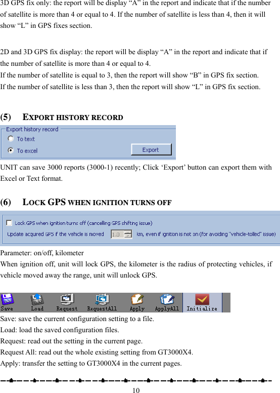
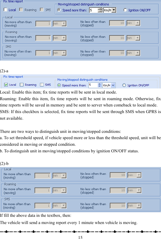
![143. [REPORTS:] 3.1 FIXED REPORTS (1) INTELLIGENT HISTORY REPORT (RECORD THE REPORT IN THE SYSTEM’S FLASH RAM) Parameters: On/Off, Report time when moving, Report time when stop, and threshold speed. (Min. speed is 0.1 km/Hr, max. speed is 1000 km/Hr). If “√” is selected in the checkbox and fills the above data in the textbox, then: The vehicle will store a moving report every 5 minutes when vehicle speed exceed 18km/hr The vehicle will store a stopped report every 1 hour when vehicle speed lowers than 18km/hr (2) FIX TIME REPORT](https://usermanual.wiki/PORTMAN-ELECTRONICS/GT3000U-X4/User-Guide-1560805-Page-15.png)
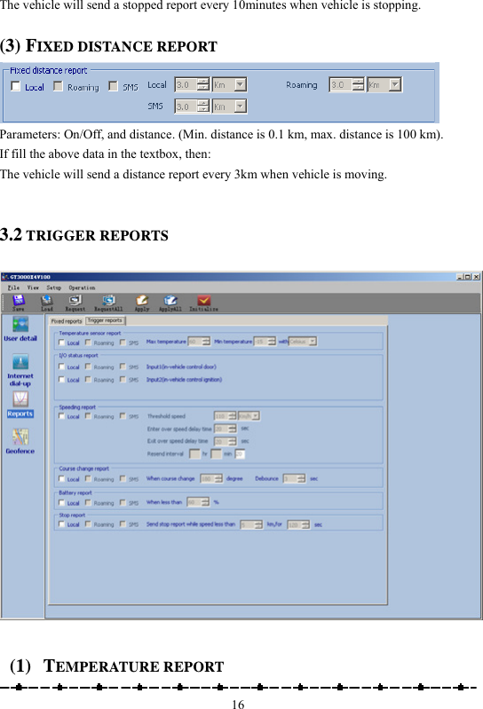
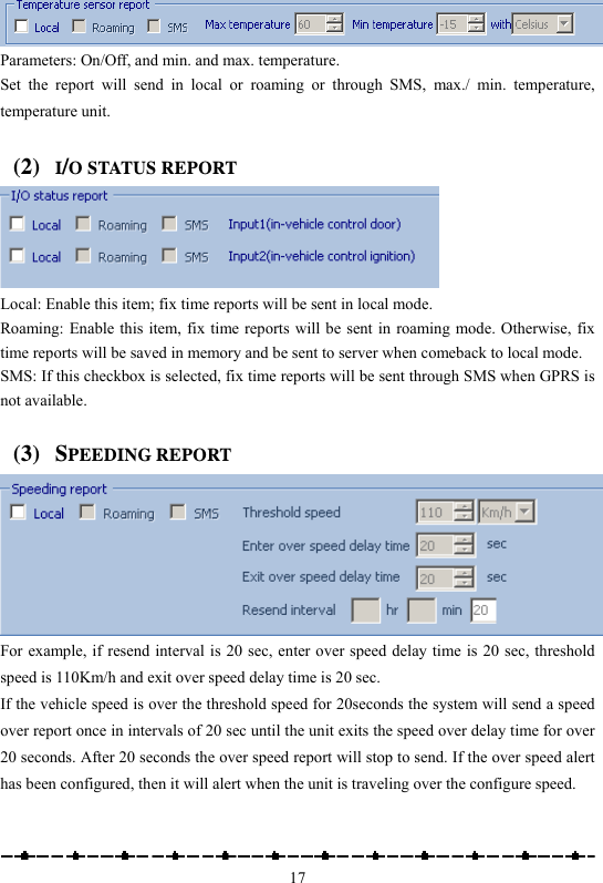
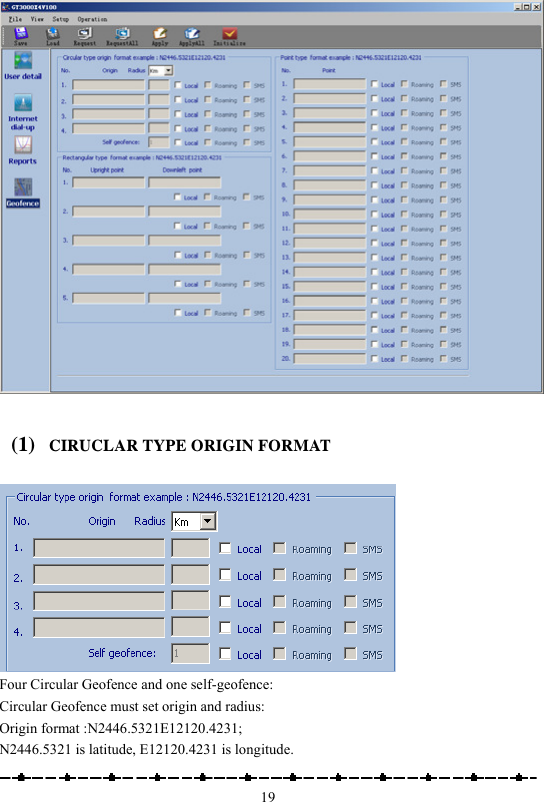
![18(4) COURSE CHANGE REPORT Enable this item to send a report when the course change is bigger than the value set here (5) BATTERY REPORT Enable this item to send a report when the external battery level is low The system will ignore the parameter with a value ‘0’ to prevent continuous non-stop reporting. (6) STOP REPORT While the vehicle speed less than ‘5km’ and more than 120 seconds, the unit will send a stop report to server. 4. [GEO-FENCE:]](https://usermanual.wiki/PORTMAN-ELECTRONICS/GT3000U-X4/User-Guide-1560805-Page-19.png)