PORTMAN ELECTRONICS GV-8300 GPS tracking system with voice function User Manual GV8300 install manual
PORTMAN ELECTRONICS (DONGGUAN) CO., LTD. GPS tracking system with voice function GV8300 install manual
Users Manual

1
GPS&GPRS CAR ALARM GV8300
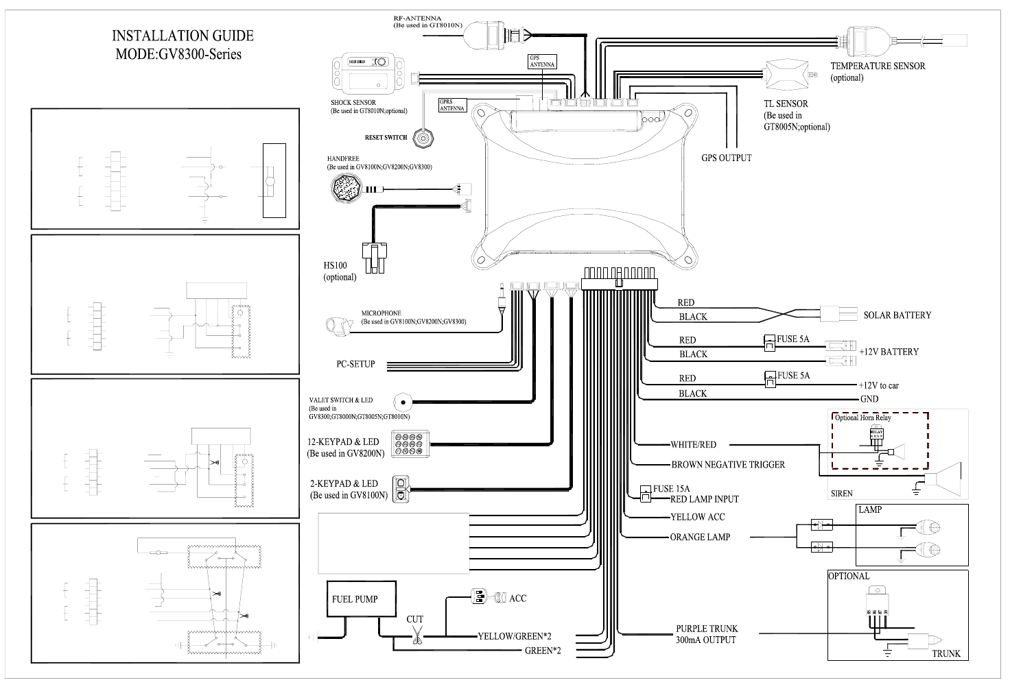
INSTALLATION MANUAL
1
REV: 1.6 (Series, GV8300V1.20, GV8300-C2)
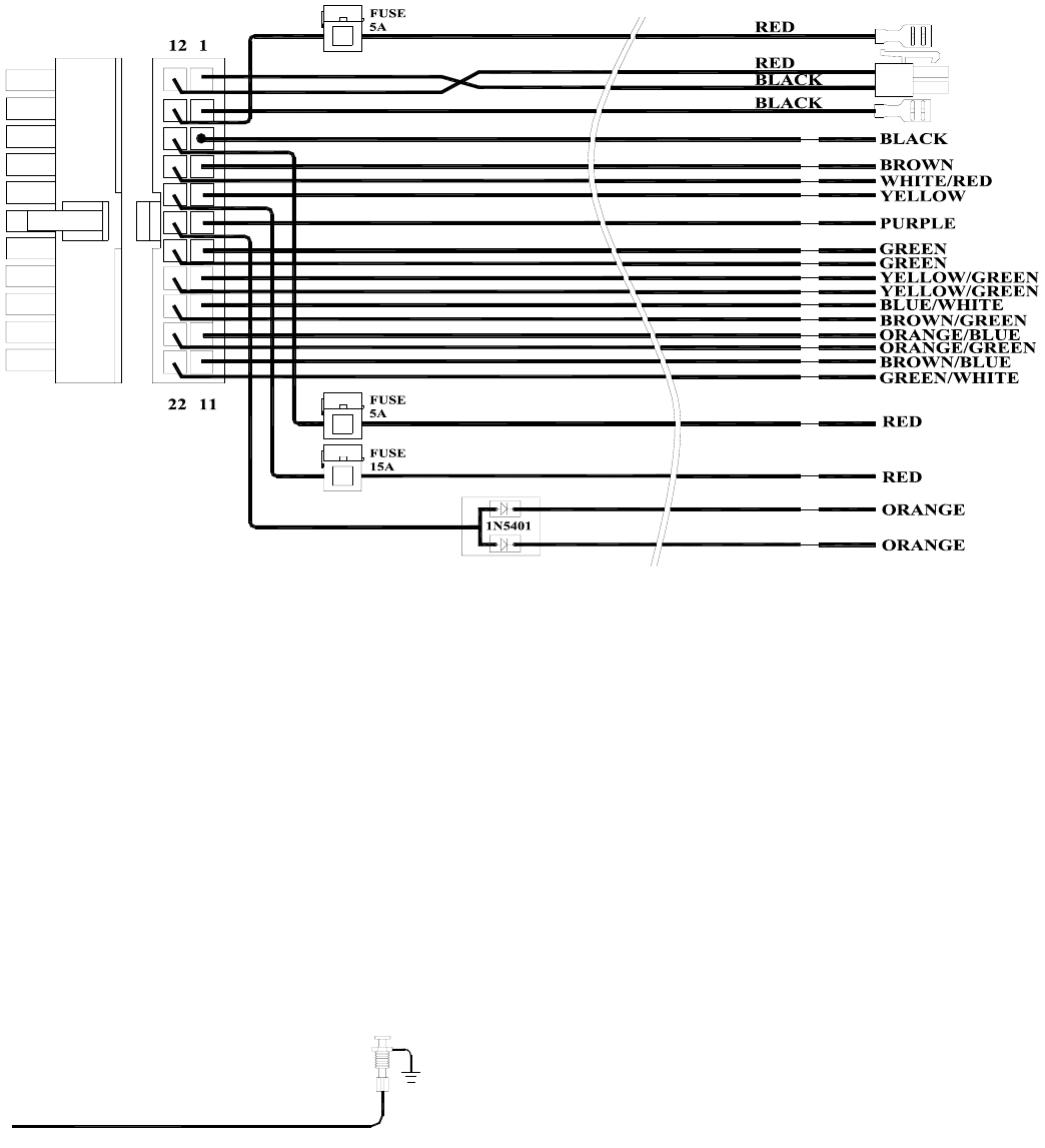
Connectors detail description
H1 2*11 connector
H1/1&H1/12:
The other terminal of the two wires is a 2PIN connector; it is very convenience to connect the solar battery board.
The solar battery board is optional; it means that if there is no solar battery board to connect, GV8300 can still work.
H1/2&H1/13:
The other sides of the two wires have especial terminal that can insert the backup battery terminal directly, the
backup battery is necessary, and it can power the GV8300 when the 12V power supply is off.
H1/3:Black wire: connect to the ground of the vehicle.
The wire connects the system ground. This is main ground connection of GV8300. Do not connect this wire to
any existing ground wires supplied by the factory wire loom, make the connection to the vehicle's frame directly.
H1/4 Brown wire –– Negative Door Switch Sensing Input –
Brown Negative Trigger
This wire is the ground trigger input wire for negative door pin switch. This wire is connection for "grounding"
type factory door pins locate the "common wire" that connects the door pin switches. Make the connection of the
brown Wire here.
H1/5 Yellow wire –– ACC Sensing Input
This wire should be connected to vehicle ACC. when the vehicle is ACC ON, the wire can sense a high voltage
to inform the GV8300 act.
2
H1/6 Purple wire –––300mA optional trunk output –
This feature allows you to remote control trunk release. Because the output current is maximum 300mA,it is
necessary to connect a relay in order to amplify the drive current.
H1/7&H1/18 Green wire –––Cut relay COM
The two wires connect to the cutter relay COM contract; the two wires have already been connected together on
PCB. The reason that uses two wires is to increase the current of cutter relay. When the system is armed, the two
wires will connect to the other two cutter relay wires(H1/8&H1/19).
H1/8&H1/19 Yellow/Green wire –––Cut relay NO
The two wires connect to the cutter relay NO contract; the two wires have already been connected together on
PCB. The reason that uses two wires is to increase the current of cutter relay. When the system is armed, the two
wires will connect to the other two cutter relay wires (H1/7&H1/18).
H1-9 Blue/White wire--- Lock COM
H1/9,H1/10,H1/11,H1/20,H1/21,H1/22 connect to the central door locking. See the drawing below.
H1-10 Orange/Blue wire--- Lock NC
H1/9,H1/10,H1/11,H1/20,H1/21,H1/22 connect to the central door locking. See the drawing below.
H1-11 Brown/Blue wire--- lock NO
H1/9,H1/10,H1/11,H1/20,H1/21,H1/22 connect to the central door locking. See the drawing below.
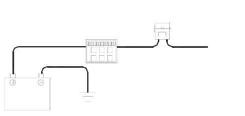
H1-14 Red wire--- Red wire – System power (+12V Constant)
The RED wire supplies power to the system. Connect this to a constant +12 volt source.
Fuse Box
BATTERY
12V
Red
Fuse 5A
H1-15 white/Red wire--- Siren output
This wire is for Siren, connect it to the RED wire of the siren, the BLACK wire of the siren connect to (-) chassis
ground.
This wire can be also connected to a horn if the customer ask for . Because the output current is maximum
300mA,it is necessary to connect a relay in order to amplify the drive current.
H1-16 Red wire---parking light input
This wire should be connected to a constant +12 volt source. It offers the power of the parking light.
H1-17 Orange wire--- (-) parking light output
This wire should be connected to the (+) parking light wire. It will supply a (+) 15A output. If the parking light
polarity fuse jumper inside the unit is moved to opposite position, this wire supplies a (-) 15A output.
3
1N5401
1N5401
Orange Parking Light
H1-20 Brown/Green Wire--- Unlock NO
H1/9,H1/10,H1/11,H1/20,H1/21,H1/22 connect to the central door locking. See the drawing below.
H1-21 Orange/green wire…Unlock NC
H1/9,H1/10,H1/11,H1/20,H1/21,H1/22 connect to the central door locking. See the drawing below.
H1-22 Green/White Wire …Unlock COM
H1/9,H1/10,H1/11,H1/20,H1/21,H1/22 connect to the central door locking. See the drawing below.
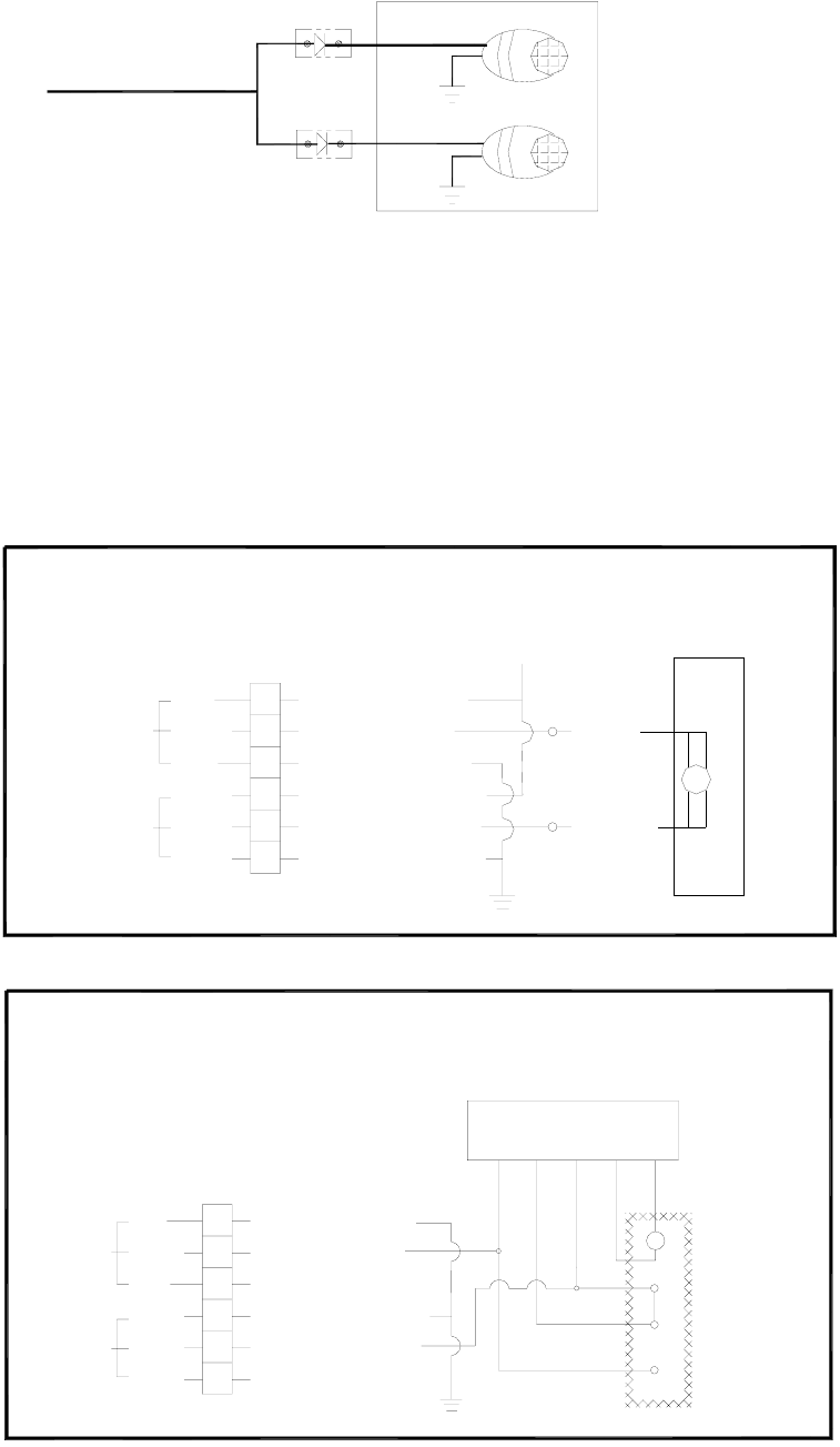
(1)FOR VEHICLES WITHOUT DRIVER SIDE LOCKING MOTOR
+12V
UNLOCK
LOCK
ORANGE/GREEN
GREEN/WHITE
ORANGE/BLUE
BROWN/GREEN
BLUE/WHITE
BROWN/BLUE
NO
COM
NC
NO
COM
NC
GREEN
BLUE
VAE:3602 ACTUATOR
COMMON
ORANGE/BLUE
NO
COM
NC
ACTUATOR
CONTROL
SWITCH
GREEN/WHITE
ORANGE/GREEN
BROWN/GREEN
NO
COM
NC
UNLOCK
(2) FOR VEHICLES WITH NEGATIVE CENTRAL LOCKING (REF
DRAWING BELOW)NOTE : WHEN THE VEHICLE IS WITH
POSITIVE CENTRAL LOCKING(CL)CONNECT BROWN/BLUE
AND BROWN/GREEN WIRES TO +12V
LOCK
BROWN/BLUE
BLUE/WHITE
VEHICLE CL
CONTROL BOX
LOCK
UNLOCK
4
VEHICLE CL
CONTROL BOX
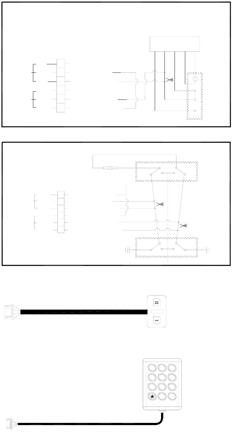
(3) FOR VEHICLES WITH POSITIVE UNLOCKING AND NEGATIVE
LOCK SIGNAL (REF DRAWING BELOW) NOTE : WHEN THE VEHICLE
IS WITH NEGATIVE, UNLOCK AND POSITIVE LOCK SWITCH
BROWN/BLUE TO +12V AND BROWN/GREEN TO GROUND
NO
COM
NC
NO
COM
NC
UNLOCK
LOCK
BROWN/BLUE GND
BROWN/GREEN +12V
ORANGE/GREEN
GREEN/WHITE
BLUE/WHITE
ORANGE/BLUE
UNLOCK
CUT
ACTUATOR
CONTROL
SWITCH
LOCK UNLOCK
CUT
(4) FOR VEHICLE WITH DIRECT SWITCHING CENTRAL LOCKING
NO
COM
NC
NO
COM
NC
LOCK
UNLOCK
+12V
ORANGE/GREEN
BLUE/WHITE
ORANGE/BLUE
GREEN/WHITE
BROWN/GREEN
BROWN/BLUE
CUT
PASSENGER
SIDE
DRIVER
SIDE
H2 2-Key pad port: black 4-pin connector. (Be used in GV8100N)
LED
Button 1
Button 2
H3 12-Key pad port: white 4-pin connector. (Be used in GV8200N)
123
#
9
6
7
0
8
45
5
H4 LED+VALET switch port: black 3-pin connector. (Be used in GV8300; GT8000N; GT8005N; GT8010N)
Led & Valet Switch
H5 PC setup port: white 4-pin connector.
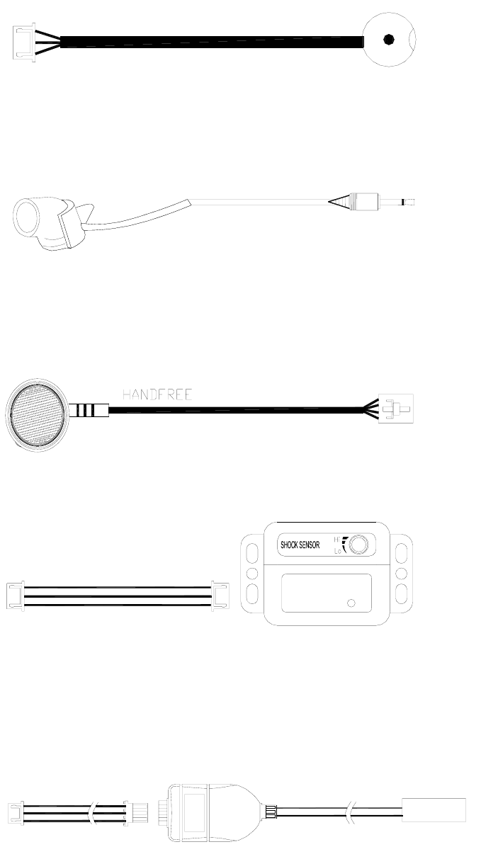
H6 MICROPHONE (be used in GV8100N; GV8200N; GV8300)
H7 Hs100 port: blue 4-pin connector. (optional)
H8 Hand free (be used in GV8100N; GV8200N; GV8300)
H9 Shock sensor or Ultrasonic sensor port: white 3-pin connector. (Be used in GT8010N; optional)
Shock Sensor
H10 RF antenna (be used in GT8010N)
H11 Temperature sensor port: blue 3-pin connector. (Optional)
OPTIONAL
TEMPERATURE SENSOR
H12 TL sensor port: red 3-pin connector. (Be used in GT8005N; optional)
H13 GPS output port: red 2-pin connector.
6
COMMON
ACTUATOR
CONTROL
SWITCH
BROWN/BLUE
BLUE/WHITE
ORANGE/BLUE
BROWN/GREEN
GREEN/WHITE
ORANGE/GREEN
NO
COM
NC
NO
COM
NC
DRIVER
SIDE
ACTUATOR
CONTROL
SWITCH
PASSENGER
SIDE
(3) FOR VEHICLES WITH POSITIVE UNLOCKING AND NEGATIVE LOCK SIGNAL
(REF DRAWING BELOW) NOTE : WHEN THE VEHICLE IS WITH NEGATIVE,UNLOCK
AND POSITIVE LOCK SWITCH BROWN/BLUE TO +12V AND BROWN/GREEN TO GROUND
LOCK UNLOCK
BROWN/BLUE
BLUE/WHITE
ORANGE/BLUE
BROWN/GREEN
GREEN/WHITE
ORANGE/GREEN
NO
COM
NC
NO
COM
NC
UNLOCK CUT
LOCK CUT
UNLOCK
+12V
(4) FOR VEHICLE WITH DIRECT SWITCHING CENTRAL LOCKING
+12V
BROWN/BLUE
BLUE/WHITE
ORANGE/BLUE
BROWN/GREEN
GREEN/WHITE
ORANGE/GREEN
NO
COM
NC
NO
COM
NC
UNLOCK
LOCK
CUT
GND
VEHICLE CL
CONTROL BOX
UNLOCK
TRUNK
+12V
RELAY
+12V
1N5401
1N5401
CENTRAL
LOCKING
INTERFACE
CONNECTIONS
(2) FOR VEHICLES WITH NEGATIVE CENTRAL LOCKING (REF DRAWING BELOW)
GREEN
NO
COM
NC
NO
COM
NC
BROWN/BLUE
BLUE/WHITE
ORANGE/BLUE
BROWN/GREEN
GREEN/WHITE
ORANGE/GREEN
UNLOCK
CONTROL BOX
LOCK
LOCK
UNLOCK
VEHICLE CL
CONNECT BROWN/BLUE AND BROWN/GREEN WIRES TO +12V
NOTE : WHEN THE VEHICLE IS WITH POSITIVE CENTRAL LOCKING,
LOCK BLUE
+12V
(1) FOR VEHICLES WITHOUT DRIVER SIDE LOCKING MOTOR
VAE:3602 ACTUATOR
7
Federal Communications Commission (FCC) Statement
This equipment has been tested and found to comply with the limits for a Class B digital device, pursuant to
part 15 of the FCC rules. These limits are designed to provide reasonable protection against harmful
interference in a residential installation. This equipment generates, uses and can radiate radio frequency
energy and, if not installed and used in accordance with the instructions, may cause harmful interference to
radio communications. However, there is no guarantee that interference will not occur in a particular
installation. If this equipment does cause harmful interference to radio or television reception, which can be
determined by turning the equipment off and on, the user is encouraged to try to correct the interference by
one or more of the following measures:
You are cautioned that changes or modifications not expressly approved by the party responsible for
compliance could void your authority to operate the equipment.
Operation is subject to the following two conditions:
1) this device may not cause interference and
2) this device must accept any interference, including interference that may cause undesired operation of the
device.
FCC RF Radiation Exposure Statement:
1. This Transmitter must not be co-located or operating in conjunction with any other antenna or
transmitter.
2. This equipment complies with FCC RF radiation exposure limits set forth for an uncontrolled
environment.