PROFORM Treadmill Manual L0802307
User Manual: PROFORM PROFORM Treadmill Manual PROFORM Treadmill Owner's Manual, PROFORM Treadmill installation guides
Open the PDF directly: View PDF ![]() .
.
Page Count: 19
PRO.FORM"
CROS "WA L
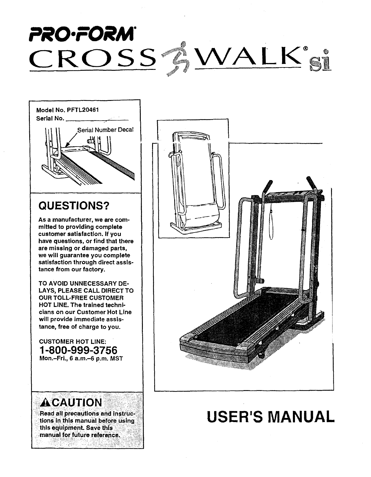
Model No. PFTL20461
Serial No. .. • ..........
7
Serial Number Decal
QUESTIONS?
As a manufacturer, we are com-
mitted to providing complete
customer satisfaction. If you
have questions, or find that there
are missing or damaged parts,
we will guarantee you complete
satisfaction through direct assis-
tance from our factory.
TO AVOID UNNECESSARY DE-
LAYS, PLEASE CALL DIRECT TO
OUR TOLL-FREE CUSTOMER
HOT LINE. The trained techni-
cians on our Customer Hot Line
will provide immediate assis-
tance, free of charge to you.
CUSTOMER HOT LINE:
1-800-999-3756
Mon.-Fri., 6 a.m.-6 p.m. MST
USER'S MANUAL
PRO.FORM"
CROSS
-- _F P.ONTPNTS
r_ PORTANT PRECAUTIONS ................................................................. 3
BEFORE YOU BEGIN ....................................................................... 4
ASSEMBLY ............................................................................... 5
OPERATION AND ADJUSTMENT ............................................................. 7
HOW TO FOLD AND MOVE THE TREADMILL .................................................. 10
TROUBLE'SHOOTING ..................................................................... 12
CONDITIONING GUIDELINES ............................................................... 14
ORDERING REPLACEMENT PARTS .................................................. Back Cover
LIMITED WARRANTY. .............................................................. Back Cover
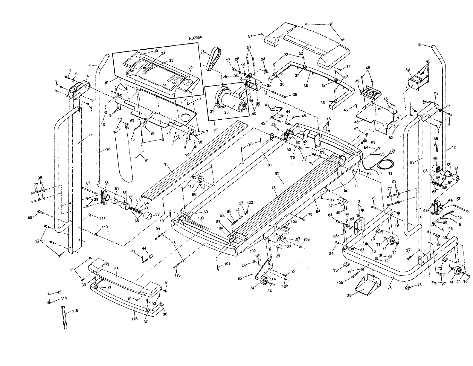
Note: An EXPLODED DRAWING and a PART LIST are attached to the center of this manual. Save the
EXPLODED DRAWING and PART LIST for future reference.
IM_TANT PRECAUTIONS
BEFORE YOU BEGIN
Thank you for selecting the PROFORM ®CROSS-
WALK si treadmill. The CROSSWALK si treadmill
combines advanced technology with innovative design
to offer you an excellent form of cardiovascular exer-
cise, in the convenience and privacy of your home.
And when you're not exercising, the unique CROSS-
WALK si can be folded up, requiring less than half the
floor space of other treadmills.
For your benefit, read this manual carefully before
using the treadmill, if you have additional questions,
please call our Customer Service Department toll-free
at 1-800-999-3756, Monday through Friday, 6 a.m.
until 6 p.m. Mountain Time (excluding holidays). To
help us assist you, please note the product model
number and serial number before calling. The model
number of the treadmill is PFTL20461. The sedal num-
ber can be found on a decal attached to the treadmill
(see the front cover of this manual for the location).
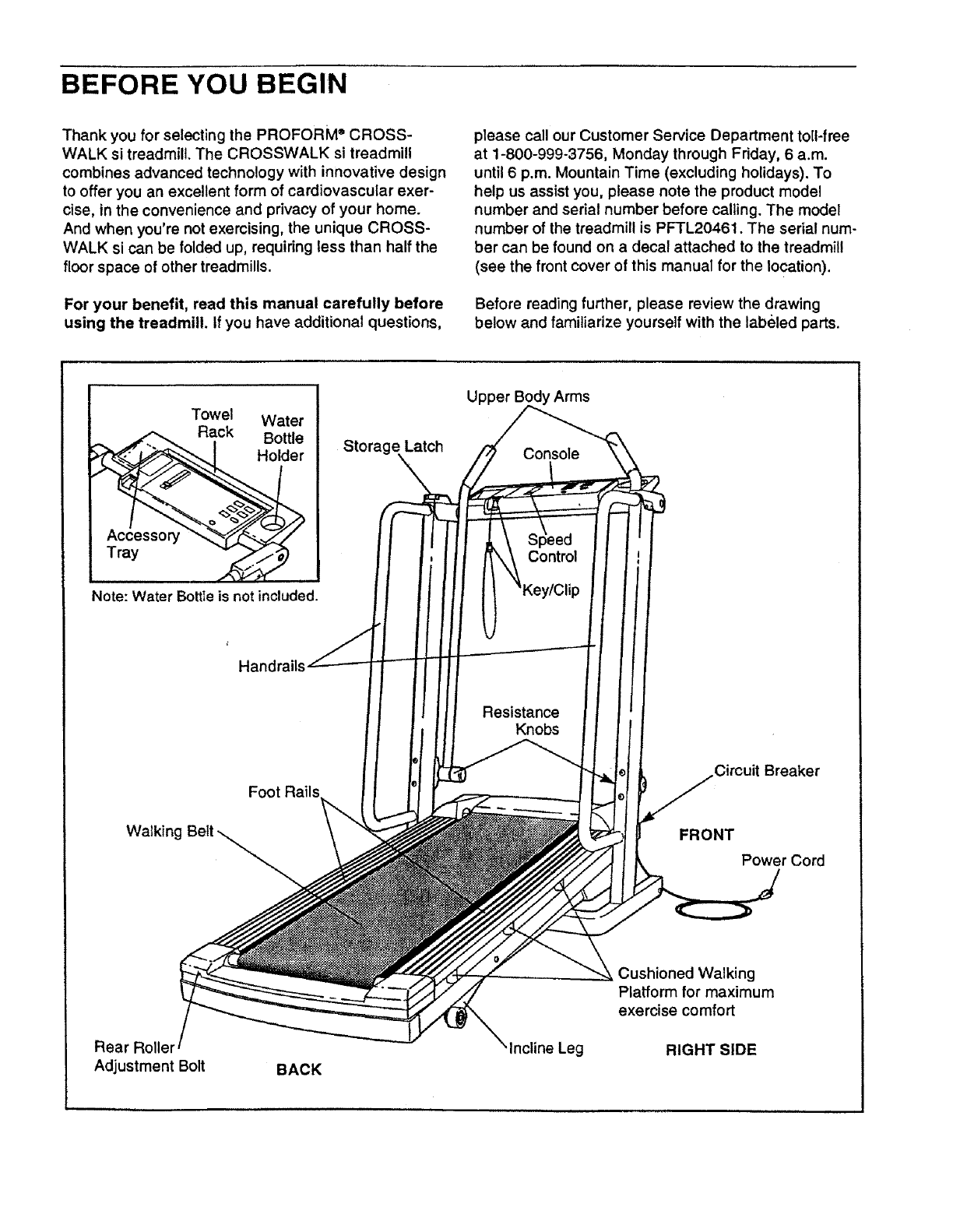
Before reading further, please review the drawing
below and familiarize yourself with the labeled parts.
Towel Water
Rack Bottle
Holder
Note: Water BottIe is not included.
Storage Latch
Upper Arms
Console
Control
Handrails
Resistance
Knobs
Walking
Foot Rails
Circuit Breaker
FRONT
Power Cord
Rear Rollel
Adjustment Bolt BACK
Incline Leg
Cushioned Walking
Platform for maximum
exercise comfort
RIGHT SIDE
ASSEMBLY
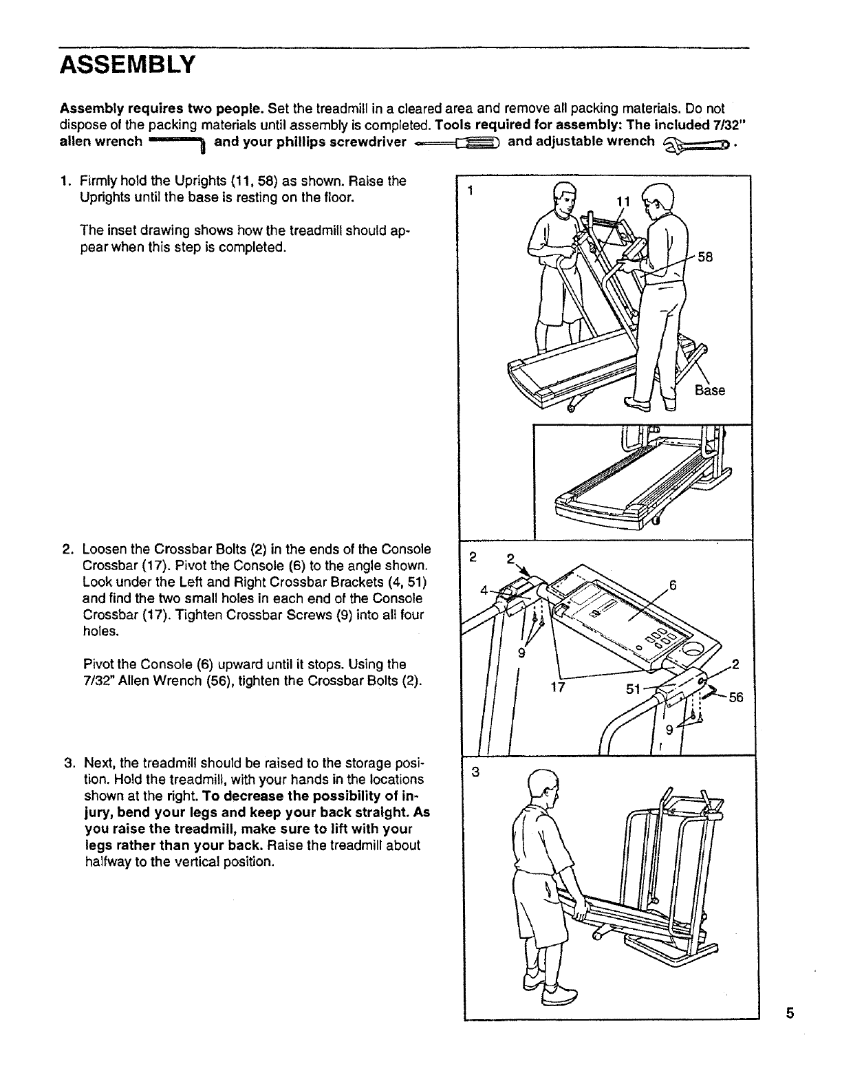
Assembly requires two people. Set the treadmill in a cleared area and remove all packing materials. Do not
dispose of the packing materials until assembly is completed. Tools required for assembly: The included 7/32"
allen wrench ='="==_ and your phillips screwdriver _and adjustable wrench _;;;;;;;:::_.
1. Firmly hold the Uprights (11, 58) as shown. Raise the
Uprights until the base is resting on the floor.
The inset drawing shows how the treadmill should ap-
pear when this step is completed.
,Loosen the Crossbar Bolts (2) in the ends of the Console
Crossbar (17). Pivot the Console (6) to the angle shown.
Look under the Left and Right Crossbar Brackets (4, 51)
and find the two small holes in each end of the Console
Crossbar (17). Tighten Crossbar Screws (9) into alt four
holes.
Pivot the Console (6) upward until it stops. Using the
7/32" Allen Wrench (56), tighten the Crossbar Bolts (2).
3. Next, the treadmill should be raised to the storage posi-
tion. Hold the treadmill, with your hands in the locations
shown at the right. To decrease the possibility of in-
jury, bend your legs and keep your back straight. As
you raise the treadmill, make sure to lift with your
legs rather than your back. Raise the treadmill about
halfway to the vertical position.
3
5
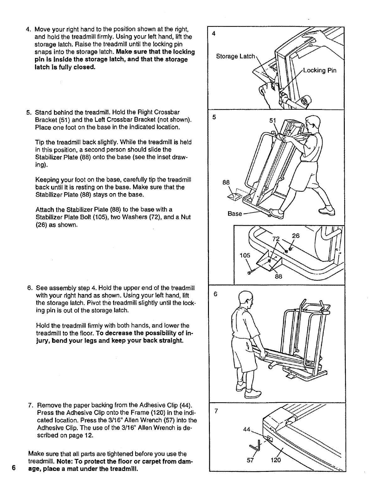
4. Move your right hand to the position shown at the right,
and hold the treadmill firmly. Using your left hand, lift the
storage latch. Raise the treadmill until the locking pin
snaps into the storage latch. Make sure that the locking
pin is inside the storage latch, and that the storage
latch is fully closed.
.Stand behind the treadmill. Hold the Right Crossbar
Bracket (51) and the Left Crossbar Bracket (not shown).
Place one foot on the base in the indicated location.
Tip the treadmill back slightly. While the treadmill is held
in this position, a second person should slide the
Stabilizer Plate (88) onto the base (see the inset draw-
ing).
Keeping your foot on the base, carefully tip the treadmill
back until it is resting on the base. Make sure that the
Stabilizer Plate (88) stays on the base.
Attach the Stabilizer Plate (88) to the base with a
Stabilizer Plate Bolt (105), two Washers (72), and a Nut
(26) as shown.
.See assembly step 4. Hold the upper end of the treadmill
with your right hand as shown. Using your left hand, lift
the storage latch. Pivot the treadmill slightly until the lock-
ing pin is out of the storage latch.
Hold the treadmill firmly with both hands, and lower the
treadmill to the floor. To decrease the possibility of in-
jury, bend your legs and keep your back straight.
7. Remove the paper backing from the Adhesive Clip (44).
Press the Adhesive Clip onto the Frame (120) in the indi-
cated location. Press the 3/16" Allen Wrench (57) into the
Adhesive Clip. The use of the 3/16" Allen Wrench is de-
scribed on page 12.
Make sure that all parts are tightened before you use the
treadmill. Note: To protect the floor or carpet from dam-
age, place a mat under the treadmill.
Pin
5 51
Base _
26
105
88
7
57 120
OPERATION AND ADJUSTMENT
THE PERFORMANT LUBE TM WALKING BELT
Your treadmill features a walking belt coated with
PERFORMANT LUBE TM, a high-performance lubricant.
IMPORTANT: Never apply silicone spray or other
substances to the walking belt or the walking plat-
form. They will deteriorate the walking belt and
cause excessive wear.
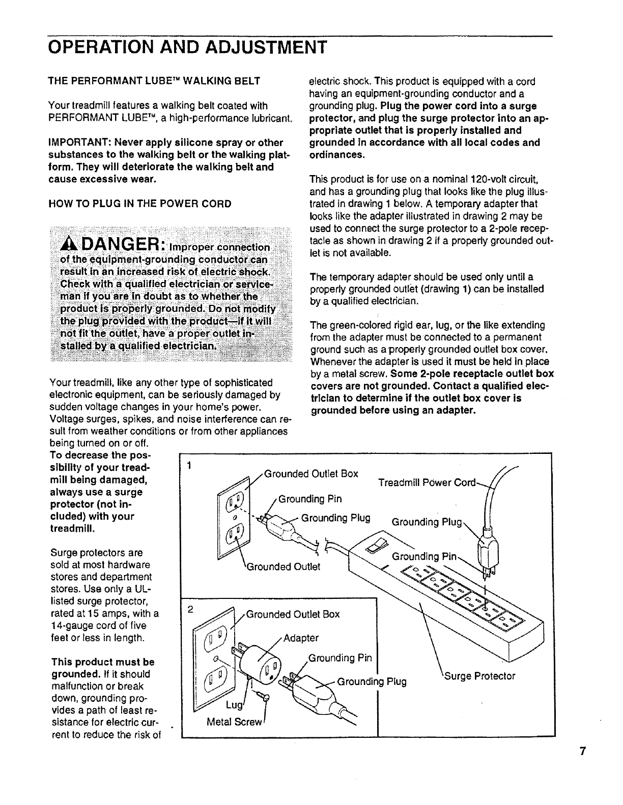
HOW TO PLUG IN THE POWER CORD
electric shock. This product is equipped with a cord
having an equipment-grounding conductor and a
grounding plug. Plug the power cord into a surge
protector, and plug the surge protector into an ap-
propriate outlet that is properly installed and
grounded in accordance with all local codes and
ordinances.
This product is for use on a nominal 120-volt circuit,
and has a grounding plug that looks like the plug illus-
trated in drawing 1 below. A temporary adapter that
looks like the adapter illustrated in drawing 2 may be
used to connect the surge protector to a 2-pole recep-
tacle as shown in drawing 2 if a properly grounded out-
let is not available.
The temporary adapter should be used only until a
properly grounded outlet (drawing 1) can be installed
by a qualified electrician.
Your treadmill, like any other type of sophisticated
electronic equipment, can be seriously damaged by
sudden voltage changes in your home's power.
Voltage surges, spikes, and noise interference can re-
sult from weather conditions or from other appliances
being turned on or off.
To decrease the pos-
sibility of your tread- 1
mill being damaged,
always use a surge
protector (not in-
cluded) with your
treadmill.
Surge protectors are
sold at most hardware
stores and department
stores. Use onty a UL-
listed surge protector,
rated at 15 amps, with a
14-gauge cord of five
feet or less in length.
This product must be
grounded. If it should
malfunction or break
down, grounding pro-
vides a path of least re-
sistance for electric cur-
rent to reduce the risk of
The green-colored rigid ear, lug, or the like extending
from the adapter must be connected to a permanent
ground such as a'properly grounded outlet box cover.
Whenever the adapter is used it must be held in place
by a metal screw. Some 2-pole receptacle outlet box
covers are not grounded. Contact a qualified elec-
trician to determine if the outlet box cover is
grounded before using an adapter.
/Grounded Outlet Box
/Grounding Pin
'_unding Plug
3rounded Outlet
Treadmill
Grounded Outlet Box
Adapter
_g .Grounding Pin
(l,
Metal Screw _I
Surge Protector
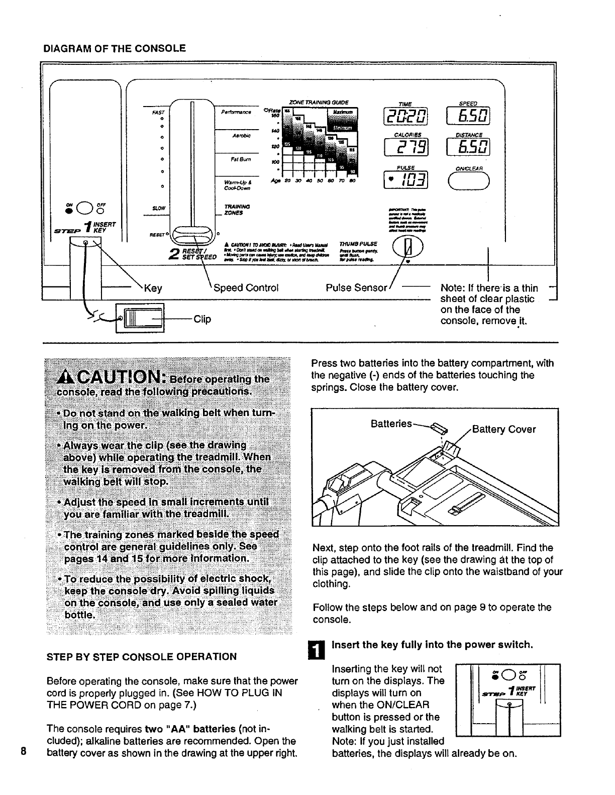
DIAGRAMOFTHECONSOLE
;O s"
t_ INSERT
_71_p If KEY
_ r
FAST
o
o
o
o
o
o
o
SLOW
_RES
_SET
Key
$PEEO
[ .so
ON_LF_R
Note: If there'is a thin
sheet of clear plastic
on the face of the
console, remove it.
STEP BY STEP CONSOLE OPERATION
Before operating the console, make sure that the power
cord is properly plugged in. (See HOW TO PLUG IN
THE POWER CORD on page 7.)
The console requires two "AA" batteries (not in-
cluded); alkaline batteries are recommended. Open the
battery cover as shown in the drawing at the upper right,
Press two batteries into the battery compartment, with
the negative (-) ends of the batteries touching the
springs. Close the battery cover.
Next, step onto the foot rails of the treadmill. Find the
clip attached to the key (see the drawing a.t the top of
this page), and slide the clip onto the waistband of your
clothing.
Follow the steps below and on page 9to operate the
console.
aInsert the key fully into the power switch.
Inserting the key will not
turn on the displays. The
displays will turn on
when the ON/CLEAR
button is pressed or the
walking belt is started.
Note: If you just installed
,!
batteries, the displays will already be on.
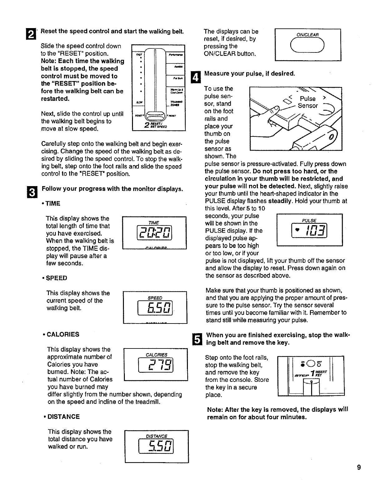
_Reset the speed control and start the walking belt.
Slide the speed control down
to the "RESET" position.
Note: Each time the walking
belt is stopped, the speed
control must be moved to
the "RESET" position be-
fore the walking belt can be
restarted.
Next, slide the control up until
the walking belt begins to
move at slow speed.
o
II
m _ZONI_
RESET/
2_£'r _EED
Carefully step onto the walking belt and begin exer-
cising. Change the speed of the walking belt as de-
sired by sliding the speed control. To stop the walk-
ing belt, step onto the foot rails and slide the speed
control to the "RESET" position.
Follow your progress with the monitor displays.
•TIME
This display shows the
total length of time that
you have exercised.
When the walking belt is
stopped, the TIME dis-
play will pause after a
few seconds.
TIME
[p pr l
_u_ u!
•SPEED
This display shows the
current speed of the
walking belt.
.CALORIES
This display shows the
approximate number of
Calories you have
burned. Note: The ac-
tual number of Calories
you have burned may
differ slightly from the number shown, depending
on the speed and incline of the treadmill.
CALORIES
[ P -'°1
•DISTANCE
The displays can be
reset, if desired, by
pressing the
ON/CLEAR button.
ON, K;LEAR
BMeasure your pulse, if desired.
To use the
pulse sen-
sor, stand
on the foot
rails and
place your
thumb on
the pulse
sensor as
shown. The
-J AS)
pulse sensor is pressure-activated. Fully press down
the pulse sensor. Do not press too hard, or the
circulation in your thumb will be restricted, and
your pulse will not be detected. Next, slightly raise
your thumb until the heart-shaped indicator in the
PULSE display flashes steadily. Hold your thumb at
this level. After 5 to 10
seconds, your pulse
will be shown in the PULSE
Imp/1
PULSE display. If the t IU3'J
displayed pulse ap-
pears to be too high
or too low, or if your
pulse is not displayed, lift your thumb off the sensor
and allow the display to reset. Press down again on
the sensor as descdbed above.
Make sure that your thumb is positioned as shown,
and that you are applying the proper amount of pres-
sure to the pulse sensor. Try the sensor several
times until you become familiar with it. Remember to
stand still while measuring your pulse.
When you are finished exercising, stop the walk-
ing belt and remove the key.
Step onto the foot rails,
stop the walking belt,
and remove the key
from the console. Store
the key in a secure
place.
Note: After the key is removed, the displays will
remain on for about four minutes.
This display shows the
total distance you have
walked or run.
DISTANCE
_l.J
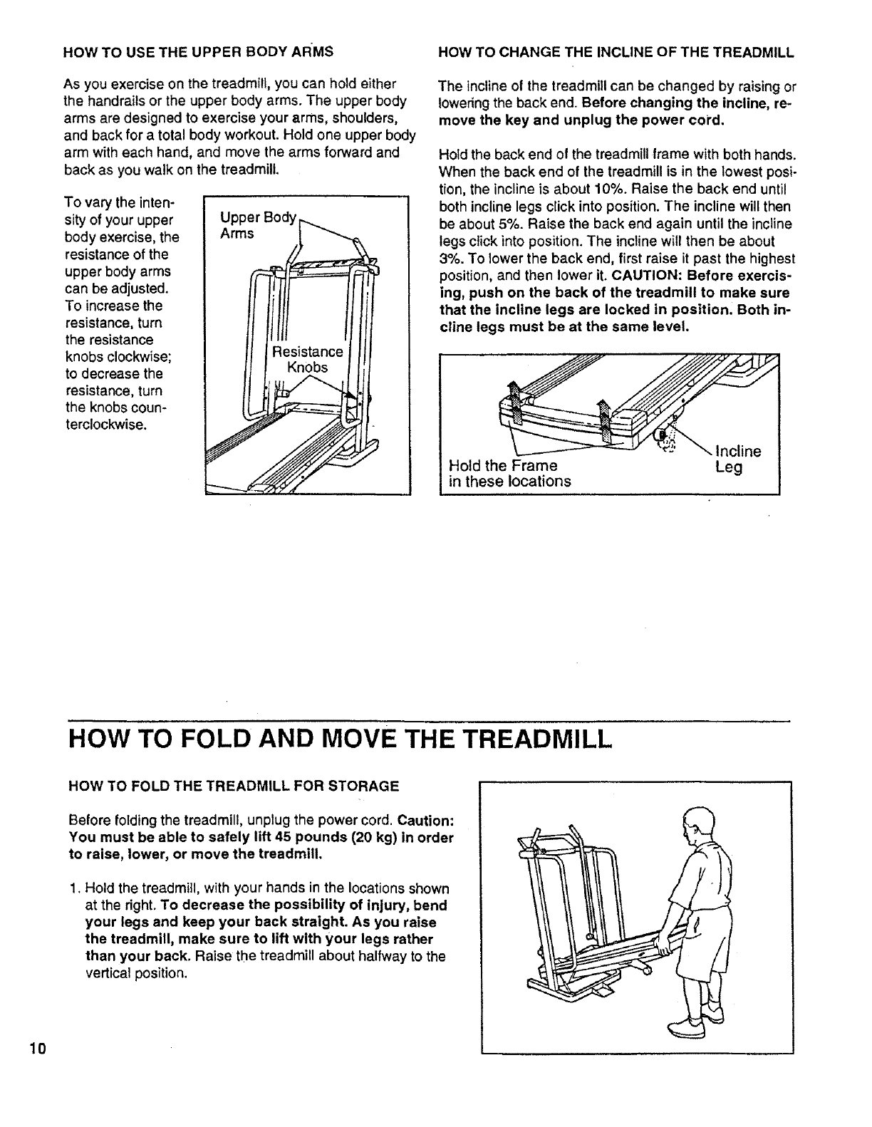
HOW TO USE THE UPPER BODY ARMS
As you exercise on the treadmill, you can hold either
the handrails or the upper body arms. The upper body
arms are designed to exercise your arms, shoulders,
and back for a total body workout. Hold one upper body
arm with each hand, and move the arms forward and
back as you walk on the treadmill.
To vary the inten-
sity of your upper
body exercise, the
resistance of the
upper body arms
can be adjusted.
To increase the
resistance, turn
the resistance
knobs clockwise;
to decrease the
resistance, turn
the knobs coun-
terclockwise.
HOW TO CHANGE THE INCLINE OF THE TREADMILL
The incline ot the treadmill can be changed by raising or
lowering the back end. Before changing the incline, re-
move the key and unplug the power cord.
Hold the back end of the treadmill frame with both hands.
When the back end of the treadmill is in the lowest posi-
tion, the incline is about 10%. Raise the back end until
both incline legs click into position. The incline will then
be about 5%. Raise the back end again until the incline
legs click into position. The incline will then be about
3%. To lower the back end, first raise it past the highest
position, and then lower it. CAUTION: Before exercis-
ing, push on the back of the treadmill to make sure
that the incline legs are locked in position. Both in-
cline legs must be at the same level.
_-. Incline
Hold the Frame Leg
in these locations
HOW TO FOLD AND MOVE THE TREADMILL
10
HOW TO FOLD THE TREADMILL FOR STORAGE
Before folding the treadmill, unplug the power cord. Caution:
You must be able to safely lift 45 pounds (20 kg) in order
to raise, lower, or move the treadmill.
1. Hold the treadmill, with your hands in the locations shown
at the dght. To decrease the possibility of injury, bend
your legs and keep your back straight. As you raise
the treadmill, make sure to lift with your legs rather
than your back. Raise the treadmill about halfway tothe
vertical position.
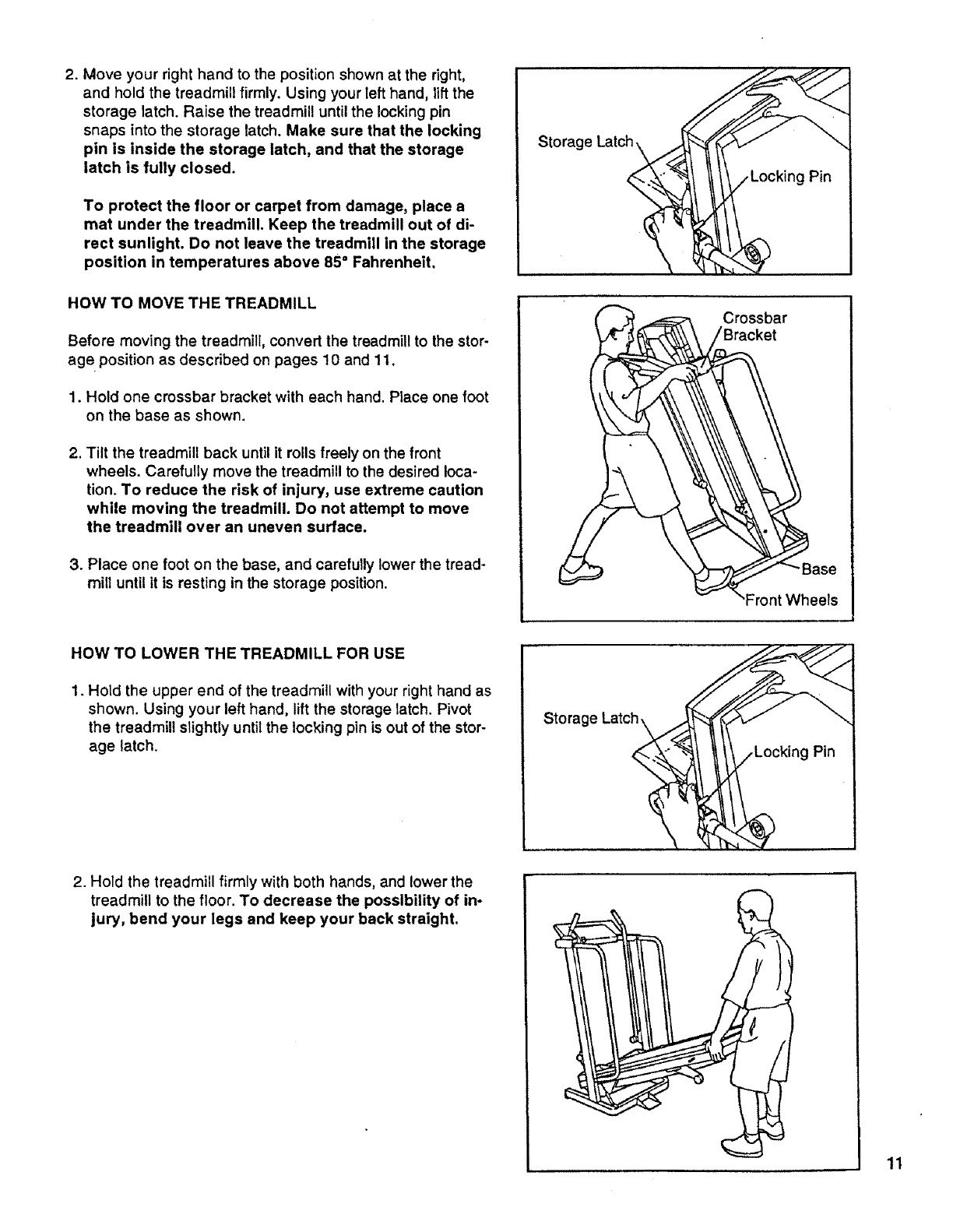
2.Moveyourrighthandtothepositionshownattheright,
andholdthetreadmillfirmly.Usingyourlefthand,liftthe
storagelatch.Raisethetreadmilluntilthelockingpin
snapsintothestoragelatch.Make sure that the locking
pin is inside the storage latch, and that the storage
latch is fully closed.
To protect the floor or carpet from damage, place a
mat under the treadmill. Keep the treadmill out of di-
rect sunlight. Do not leave the treadmill in the storage
position in temperatures above 85°Fahrenheit.
HOW TO MOVE THE TREADMILL
Before moving the treadmill, convert the treadmill to the stor-
age position as described on pages 10 and 11.
1. Hold one crossbar bracket with each hand. Place one foot
on the base as shown.
2. Tilt the treadmill back until it rolls freely on the front
wheels. Carefully move the treadmill to the desired loca-
tion. To reduce the risk of injury, use extreme caution
while moving the treadmill. Do not attempt to move
the treadmill over an uneven surface.
3. Place one foot on the base, and carefully lower the tread-
mill until it is resting in the storage position.
HOW TO LOWER THE TREADMILL FOR USE
1. Hold the upper end of the treadmill with your right hand as
shown. Using your left hand, lift the storage latch. Pivot
the treadmill slightly until the locking pin is out of the stor-
age latch.
Storage Latch
_"_ocking Pin
..,_. Crossbar
Base
- "Front Wheels
Pin
2. Hold the treadmill firmly with both hands, and lower the
treadmill to the floor. To decrease the possibility of in-
jury, bend your legs and keep your back straight.
11
TROUBLE-SHOOTING
Most treadmill problems can be solved by following the steps below. Find the symptom that applies, and
follow the steps listed, if further assistance is needed, please call our Customer Service Department toll-
free at 1-800-999-3756, Monday through Friday, 6 a.m. until 6 p.m. Mountain Time (excluding holidays).
1. SYMPTOM: THE POWER DOES NOT TURN ON
a. Make sure that the power cord is plugged into a surge protector, and that the surge protector is plugged into
a properly grounded outlet. (See HOW TO PLUG IN THE POWER CORD on page 7.) Use only a UL-listed
surge protector, rated at 15 amps, with a 14-gauge cord of five feet or less in length.
b. After the power cord has been plugged in, make sure that the key is fully inserted into the console. (See step
1 on page 8.)
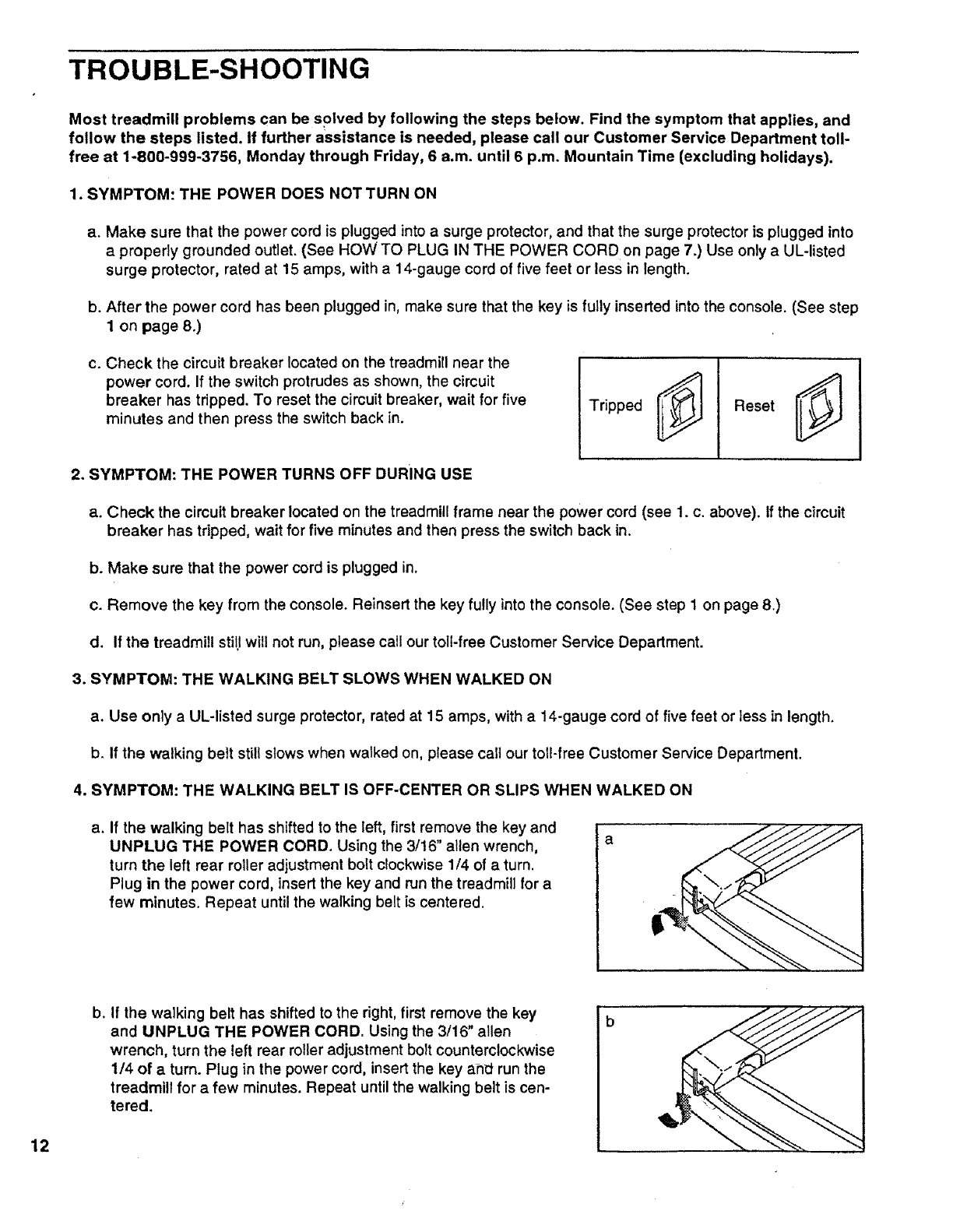
C. Check the circuit breaker located on the treadmill near the
power cord. If the switch protrudes as shown, the circuit
breaker has tripped. To reset the circuit breaker, wait for five
minutes and then press the switch back in. Tripped Reset
2. SYMPTOM: THE POWER TURNS OFF DURING USE
a. Check the circuit breaker located on the treadmill frame near the power cord (see 1. c. above). If the circuit
breaker has tripped, wait for five minutes and then press the switch back in.
b. Make sure that the power cord is plugged in.
c. Remove the key from the console. Reinsert the key fully into the console. (See step 1 on page 8.)
d. If the treadmill still will not run, please call our toll-free Customer Service Department.
3. SYMPTOM: THE WALKING BELT SLOWS WHEN WALKED ON
a. Use only aUL-listed surge protector, rated at 15 amps, with a 14-gauge cord of five feet or less in length.
b. If the walking belt still slows when walked on, please call our toll-free Customer Service Department.
4. SYMPTOM: THE WALKING BELT IS OFF-CENTER OR SLIPS WHEN WALKED ON
a. If the walking belt has shifted to the left, first remove the key and
UNPLUG THE POWER CORD. Using the 3/16" allen wrench,
turn the left rear roller adjustment bolt clockwise 1/4 of a turn.
Plug in the power cord, insert the key and run the treadmill for a
few minutes. Repeat until the walking belt is centered.
12
b. If the walking belt has shifted to the right, first remove the key
and UNPLUG THE POWER CORD. Using the 3/16" allen
wrench, turn the left rear roller adjustment bolt counterclockwise
1/4 of a turn. Plug in the power cord, insert the key and run the
treadmill for a few minutes. Repeat until the walking belt is cen-
tered.
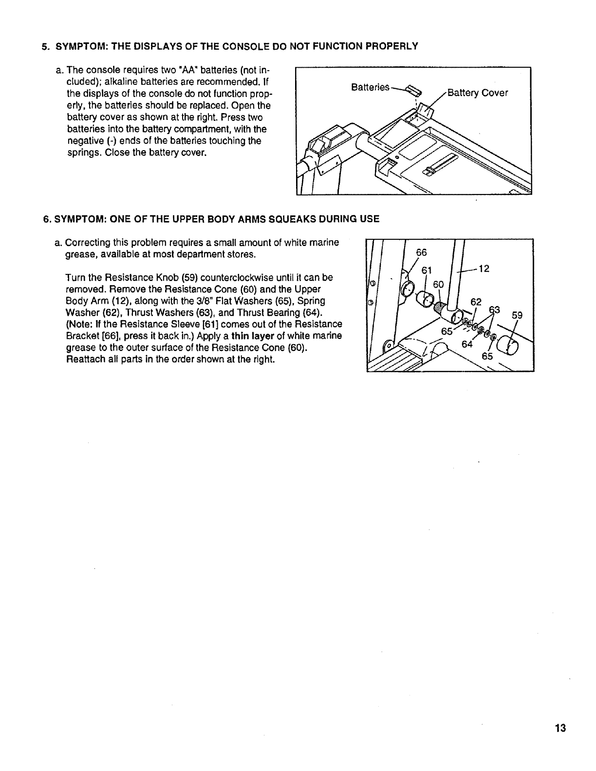
5. SYMPTOM: THE DISPLAYS OF THE CONSOLE DO NOT FUNCTION PROPERLY
a. The console requires two "AA" batteries (not in-
cluded); alkaline batteries are recommended. If
the displays of the console do not function prop-
erty, the batteries should be replaced. Open the
battery cover as shown at the right. Press two
batteries into the battery compartment, with the
negative (-) ends of the batteries touching the
springs. Close the battery cover.
ICover
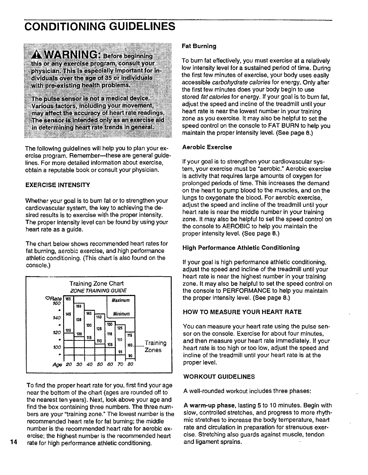
6. SYMPTOM: ONE OF THE UPPER BODY ARMS SQUEAKS DURING USE
a. Correcting this problem requires a small amount of white marine Ill III
grease, available at most department stores. !_ l 66
61 12
Turn the Resistance Knob (59) counterclockwise until it can be
removed. Remove the Resistance Cone (60) and the Upper • " 60
Body Arm (12), along with the 3/8" Flat Washers (65), Spring
Washer (62), Thrust Washers (63), and Thrust Bearing (64). 3 59
(Note: If the Resistance Sleeve [61] comes out of the Resistance 65
Bracket [66], press it back in.)Apply a thin layer of white marine 1/___. _...../.
grease to the outer surface of the Resistance Cone (60).
Reattach all parts in the order shown at the right. _...-jjj_ -,,._
13
CONDITIONING GUIDELINES
14
The following guidelines will help you to plan your ex-
ercise program. Remember--these are general guide-
lines. For more detailed information about exercise,
obtain a reputable book or consult your physician.
EXERCISE INTENSITY
Whether your goal is to burn fat or to strengthen your
cardiovascular system, the key to achieving the de-
sired results is to exercise with the proper intensity.
The proper intensity level can be found by using your
heart rate as a guide.
The chart below shows recommended heart rates for
fat burning, aerobic exercise, and high performance
athletic conditioning. (This chart is also found on the
console.)
_)Rate
160
140
120
100
Training Zone Chart
ZONE TRAINING GUIDE
16S "'--L--
14+.mlm i"+'-__
't25 12S
-- 1111
Maximum
Minimum
t0$-
g5 1.+
Age 20 30 40 50 60 70 80
__Training
Zones
To find the proper heart rate for you, first find your age
near the bottom of the chart (ages are rounded off to
the nearest ten years). Next, look above your age and
find the box containing three numbers. The three num-
bers are your "training zone." The lowest number is the
recommended heart rate for fat burning; the middle
number is the recommended heart rate for aerobic ex-
ercise; the highest number is the recommended heart
rate for high performance athletic conditioning.
Fat Burning
To burn fat effectively, you must exercise at arelatively
low intensity level for a sustained period of time. During
the first few minutes of exercise, your body uses easily
accessible carbohydrate calories for energy. Only after
the first few minutes does your body begin to use
stored fat calories for energy. If your goal is to burn fat,
adjust the speed and incline of the treadmill until your
heart rate is near the lowest number in your training
zone as you exercise. It may also be helpful to set the
speed control on the console to FAT BURN to help you
maintain the proper intensity level. (See page 8.)
Aerobic Exercise
If your goal is to strengthen your cardiovascular sys-
tem, your exercise must be "aerobic." Aerobic exercise
is activity that requires large amounts of oxygen for
prolonged periods of time. This increases the demand
on the heart to pump blood to the muscles, and on the
lungs to oxygenate the blood. For aerobic exercise,
adjust the speed and incline of the treadmill until your
heart rate is near the middle number in your training
zone. It may also be helpful to set the speed control on
the console to AEROBIC to help you maintain the
proper intensity level. (See page 8.)
High Performance Athletic Conditioning
If your goal is high performance athletic conditioning,
adjust the speed and incline of the treadmill until your
heart rate is near the highest number in your training
zone. It may also be helpful to set the speed control on
the console to PERFORMANCE to help you maintain
the proper intensity level. (See page 8.)
HOW TO MEASURE YOUR HEART RATE
You can measure your heart rate using the pulse sen-
sor on the console. Exercise for about four minutes,
and then measure your heart rate immediately. If your
heart rate is too high or too low. adjust the speed and
incline of the treadmill until your heart rate is at the
proper level.
WORKOUT GUIDELINES
A well-rounded workout includes three phases:
A warm-up phase, lasting 5to 10 minutes. Begin with
slow, controlled stretches, and progress to more rhyth-
mic stretches to increase the body temperature, heart
rate and circulation in preparation for strenuous exer-
cise, Stretching also guards against muscle, tendon
and ligament sprains.
A cardiovascularphase,including20 to 30 minutes
of exercising with your heart rate in your training zone.
(See EXERCISE INTENSITY on page 14 to find your
training zone.)
A cool-down phase, consisting of 5 to 10 minutes of
stretching. Thorough stretching offsets muscle con-
tractions and other problems caused when you stop
exercising suddenly. Stretching for increased flexibility
is also most effective during this phase. This phase
should leave you relaxed and comfortably tired.
To maintain or improve your condition, plan three
workouts each week, with at least one day of rest be-
tween workouts. After a few months of regular exer-
cise, you may complete up to five workouts each
week, if desired.
Remember, the key to success is make exercise a
regular and enjoyable part of your everyday life.
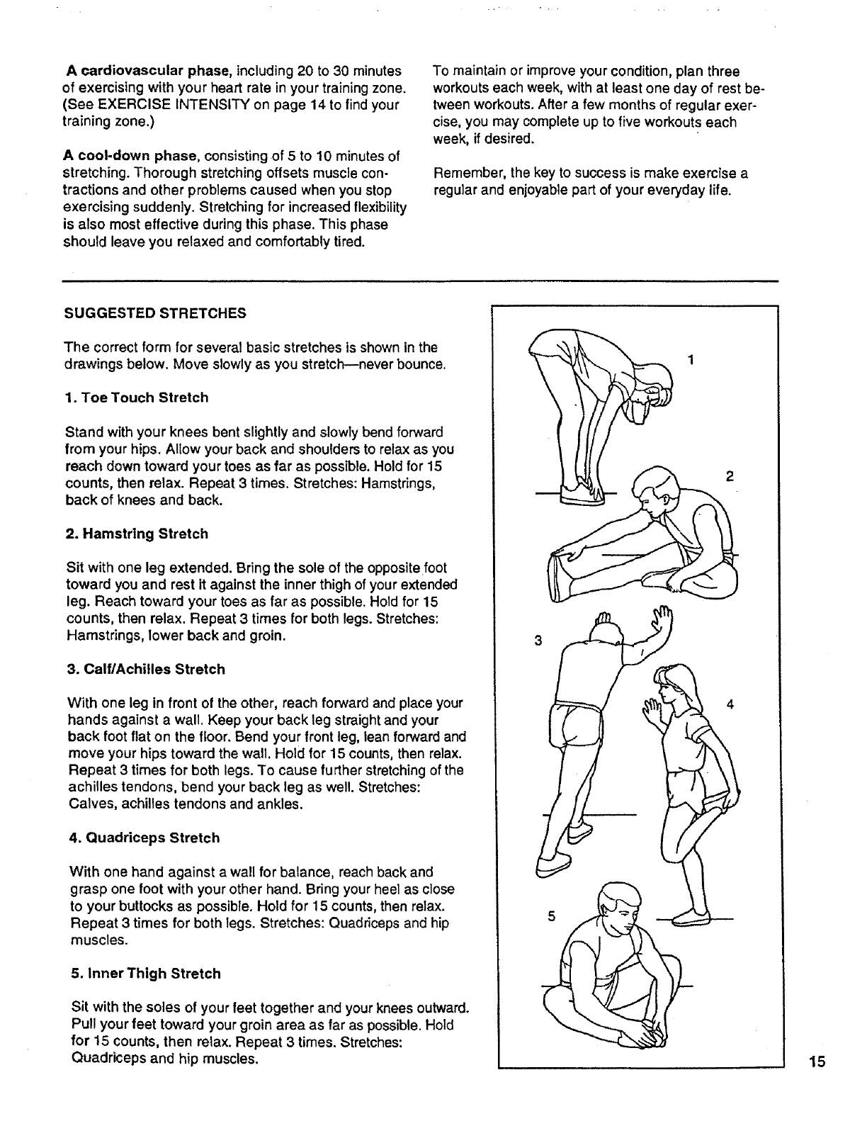
SUGGESTED STRETCHES
The correct form for several basic stretches is shown in the
drawings below. Move slowly as you stretch--never bounce.
1. Toe Touch Stretch
Stand with your knees bent slightly and slowly bend forward
from your hips. Allow your back and shoulders to relax as you
reach down toward your toes as far as possible. Hold for 15
counts, then relax. Repeat 3 times. Stretches: Hamstrings,
back of knees and back.
2. Hamstring Stretch
Sit with one leg extended. Bring the sole of the opposite foot
toward you and rest it against the inner thigh of your extended
leg. Reach toward your toes as far as possible. Hold for 15
counts, then relax. Repeat 3 times for both legs. Stretches:
Hamstrings, lower back and groin.
3. Calf/Achilles Stretch
With one leg in front of the other, reach forward and place your
hands against a wall. Keep your back leg straight and your
back foot flat on the floor. Bend your front teg, lean forward and
move your hips toward the wall. Hold for 15 counts, then relax.
Repeat 3 times for both legs. To cause further stretching of the
achilles tendons, bend your back leg as well. Stretches:
Calves, achilles tendons and ankles.
4. Quaddceps Stretch
With one hand against a wall for balance, reach back and
grasp one foot with your other hand. Bring your heel as close
to your buttocks as possible. Hold for 15 counts, then relax.
Repeat 3 times for both legs. Stretches: Quadriceps and hip
muscles.
5. Inner Thigh Stretch
Sit with the soles of your feet together and your knees outward.
Pull your feet toward your groin area as far as possible. Hold
for 15 counts, then relax. Repeat 3 times. Stretches:
Quadriceps and hip muscles. 15
IIIIIIIIIII IIII
REMOVE THIS EXPLODED DRAWING
AND PART LIST FROM THE MANUAL
Save this EXPLODED DRAWING and PART LIST for future reference.
II III
Note: Specifications are subject to change without notice. For information about
ordering replacement parts, see the back cover of the User's Manual
7 7 9
,_ 10
91 78
60
(
74 108
112
76
46
84
45
47
52
74 71
75
16
26
74 7_
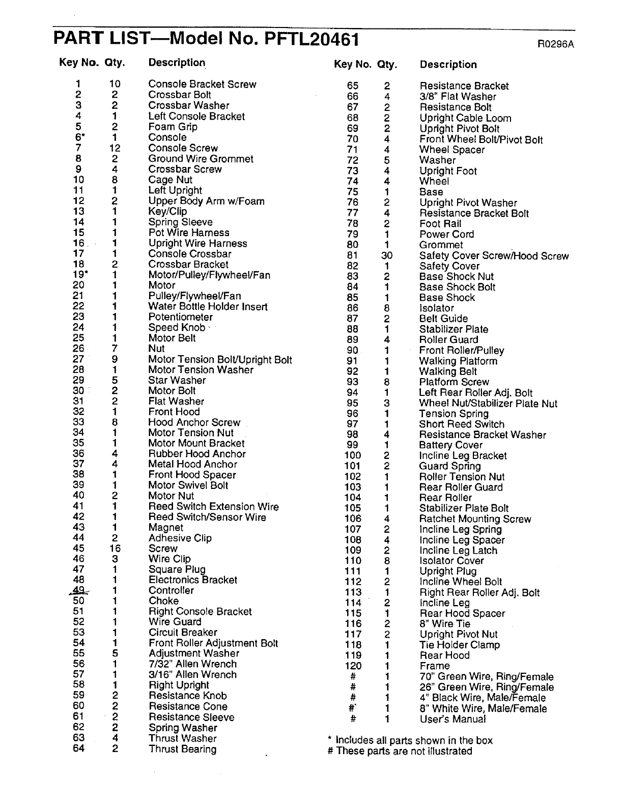
PART LIST--Model No. PFTL20461 Ro296A
Key No. Qty, Description Key No. Qty. Description
1
2
3
4
5
6*
7
8
9
10
11
12
13
14
15
16..
17
18
19"
20
21
22
23
24
25
26
27
28
29
30
31
32
33
34
35
36
37
38
39
40
41
42
43
44
45
46
47
48
5O
51
52
53
54
55
56
57
58
59
6O
61
62
63
64
10
2
2
1
2
1
12
2
4
8
1
2
1
1
1
1
1
2
1
1
1
1
1
1
1
7
9
1
5
2
2
1
8
1
1
4
4
1
1
2
1
1
1
2
16
3
1
1
1
1
1
1
1
1
5
1
1
1
2
2
22
4
2
Console Bracket Screw
Crossbar Bolt
Crossbar Washer
Left Console Bracket
Foam Grip
Console
Console Screw
Ground Wire Grommet
Crossbar Screw
Cage Nut
Left Upright
Upper Body Arm w/Foam
Key/Clip
Spring Sleeve
Pot Wire Harness
Upright Wire Harness
Console Crossbar
Crossbar Bracket
Motor/Pulley/FlywheeVFan
Motor
Pulley/Flywheel/Fan
Water Bottle Holder Insert
Potentiometer
Speed Knob-
Motor Belt
Nut
Motor Tension Bolt/Upright Bolt
Motor Tension Washer
Star Washer
Motor Bolt
Flat Washer
Front Hood
Hood Anchor Screw
Motor Tension Nut
Motor Mount Bracket
Rubber Hood Anchor
Metal Hood Anchor
Front Hood Spacer
Motor Swivel Bolt
Motor Nut
Reed Switch Extension Wire
Reed Switch/Sensor Wire
Magnet
Adhesive Clip
Screw
Wire Clip
Square Plug
Electronics Bracket
Controller
Choke
Right Console Bracket
Wire Guard
Circuit Breaker
Front Roller Adjustment Bolt
Adjustment Washer
7/32" Allen Wrench
3/16" Allen Wrench
Right Upright
Resistance Knob
Resistance Cone
Resistance Sleeve
Spring Washer
Thrust Washer
Thrust Bearing
65 2
66 4
67 2
68 2
69 2
7O 4
71 4
72 5
73 4
74 4
75 1
76 2
77 4
78 2
79 1
8O 1
81 30
82 1
83 2
84 1
85 1
86 8
87 2
88 1
89 4
90 1
91 1
92 1
93 8
94 1
95 3
96 1
97 1
98 4
99 1
100 2
101 2
102 1
103 1
104 1
105 1
106 4
107 2
108 4
109 2
110 8
111 1
112 2
113 1
114 2
115 1
116 2
117 2
118 1
119 1
120 1
# 1
# 1
# 1
#" 1
# 1
Resistance Bracket
3/8" Flat Washer
Resistance Bolt
Upright Cable Loom
Upright Pivot Bolt
Front Wheel Bolt/Pivot Bolt
Wheel Spacer
Washer
Upright Foot
Wheel
Base
Upright Pivot Washer
Resistance Bracket Bolt
Foot Rail
Power Cord
Grommet
Safety Cover Screwh-lood Screw
Safety Cover
Base Shock Nut
Base Shock Bolt
Base Shock
Isolator
Belt Guide
Stabilizer Plate
Roller Guard
Front Roller/Pulley
Walking Platform
Walking Belt
Platform Screw
Left Rear Roller Adj. Bolt
Wheel Nut/Stabilizer Plate Nut
Tension Spring
Short Reed Switch
Resistance Bracket Washer
Battery Cover
Incline Leg Bracket
Guard Spring
Roller Tension Nut
Rear Roller Guard
Rear Roller
Stabilizer Plate Bolt
Ratchet Mounting Screw
Incline Leg Spring
Incline Leg Spacer
Incline Leg Latch
Isolator Cover
Upright Plug
Incline Wheel Bolt
Right Rear Roller Adj. Bolt
Incline Leg
Rear Hood Spacer
8" Wire Tie
Upright Pivot Nut
Tie Holder Clamp
Rear Hood
Frame
70" Green Wire, Ring/Female
26" Green Wire, Ring/Female
4" Black Wire, Male/Female
8" White Wire, Male/Female
User's Manual
* Includes all parts shown in the box
# These parts are not illustrated
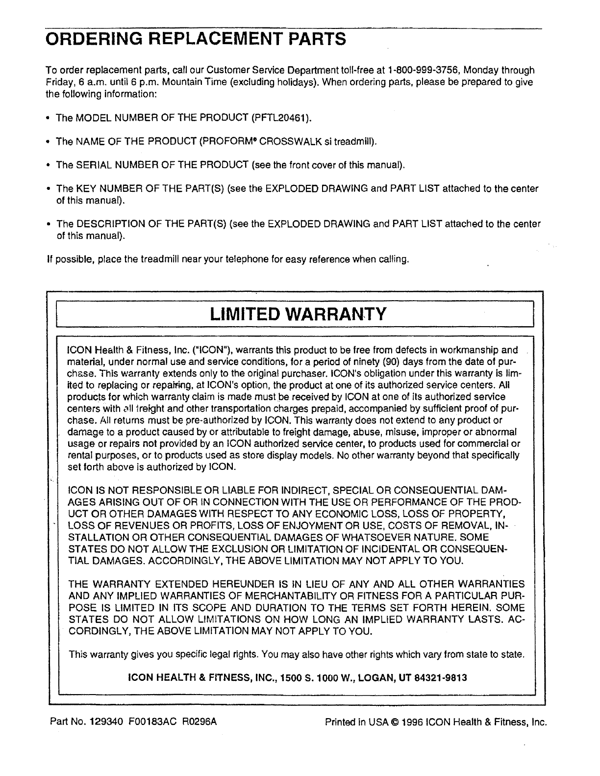
ORDERING REPLACEMENT PARTS
To order replacement parts, call our Customer Service Department toll-free at 1-800-999-3756, Monday through
Friday, 6 a.m. until 6 p.m. Mountain Time (excluding holidays). When ordering parts, please be prepared to give
the following information:
•The MODEL NUMBER OF THE PRODUCT (PFTL20461).
•The NAME OF THE PRODUCT (PROFORM ®CROSSWALK si treadmill).
•The SERIAL NUMBER OF THE PRODUCT (see the front cover of this manual).
• The KEY NUMBER OF THE PART(S) (see the EXPLODED DRAWING and PART LIST attached to the center
of this manual).
= The DESCRIPTION OF THE PART(S) (see the EXPLODED DRAWING and PART LIST attached to the center
of this manual).
If possible, place the treadmill near your telephone for easy reference when calling.
ILIMITED WARRANTY !
ICON Health & Fitness, Inc. ("ICON"), warrants this product to be free from defects in workmanship and
material, under normal use and service conditions, for a period of ninety (90) days from the date of pur-
chase. This warranty extends only to the original purchaser. ICON's obligation under this warranty is lim-
ited to replacing or repairing, at ICON's option, the product at one of its authorized service centers. All
products for which warranty claim is made must be received by ICON at one of its authorized service
centers with _ll Ireight and other transportation charges prepaid, accompanied by sufficient proof of pur-
chase. All returns must be pre-authorized by ICON. This warranty does not extend to any product or
damage to a product caused by or attributable to freight damage, abuse, misuse, improper or abnormal
usage or repairs not provided by an ICON authorized service center, to products used for commercial or
rental purposes, or to products used as store display models. No other warranty beyond that specifically
set forth above is authorized by ICON.
ICON IS NOT RESPONSIBLE OR LIABLE FOR INDIRECT, SPECIAL OR CONSEQUENTIAL DAM-
AGES ARISING OUT OF OR IN CONNECTION WITH THE USE OR PERFORMANCE OF THE PROD-
UCT OR OTHER DAMAGES WITH RESPECT TO ANY ECONOMIC LOSS, LOSS OF PROPERTY,
LOSS OF REVENUES OR PROFITS, LOSS OF ENJOYMENT OR USE, COSTS OF REMOVAL, IN-
STALLATION OR OTHER CONSEQUENTIAL DAMAGES OF WHATSOEVER NATURE. SOME
STATES DO NOT ALLOW THE EXCLUSION OR LIMITATION OF INCIDENTAL OR CONSEQUEN-
TIAL DAMAGES. ACCORDINGLY, THE ABOVE LIMITATION MAY NOT APPLY TO YOU.
THE WARRANTY EXTENDED HEREUNDER IS IN LIEU OF ANY AND ALL OTHER WARRANTIEs
AND ANY IMPLIED WARRANTIES OF MERCHANTABILITY OR FITNESS FOR A PARTICULAR PUR-
POSE IS LIMITED IN ITS SCOPE AND DURATION TO THE TERMS SET FORTH HEREIN. SOME
STATES DO NOT ALLOW LIMITATIONS ON HOW LONG AN IMPLIED WARRANTY LASTS. AC-
CORDINGLY, THE ABOVE LIMITATION MAY NOT APPLY TO YOU.
This warranty gives you specific legal rights. You may also have other rights which vary from state to state.
ICON HEALTH & FITNESS, INC., 1500 S. 1000 W., LOGAN, UT 84321-9813
Part No. 129340 F00183AC R0296A Printed in USA © 1996 ICON Health & Fitness, Inc.
