Pacific Microwave Research AT100C3 Microwave Video and Audio Transmitter User Manual AT 100C3 User s Manual REV2
Pacific Microwave Research, Inc. Microwave Video and Audio Transmitter AT 100C3 User s Manual REV2
Contents
REV 5 User Manual

Pacific Microwave Research, Inc.
AT-100 Series
Microwave Video and Audio Transmitter
USER’S MANUAL
Pacific Microwave Research, Inc.
1485 Poinsettia Avenue, Suite 111
Vista, CA 92081
760.295.5416
www.pmicrowave.com
S/N ________________

Pacific Microwave Research, Inc.
AT-100C3 User’s Manual
© 2003
1
IMPORTANT WARNING!
THIS EQUIPMENT WILL POSE A RADIATION HAZARD
IF IMPROPERLY HANDLED
Pacific Microwave Research, Inc. (PMR), in compliance with RF exposures limits set
forth in OET Bulletin 65, Fourth Edition, August, 1999.1 The following text is intended
to notify the user of PMR’s transmitter equipment that a radiation hazard could exist if
the AT-100C3 transmitter is improperly operated. The user should carefully read and
understand this section before operating equipment.
PMR’s AT-100C3 microwave transmitter is rated at 0.5W (+27 dBm) nominal RF power
output and has been designed as an intentional radiator. The transmitter may produce as
much as 1.0W (+30 dBm). The device can deliver video and audio signals over short
ranges when used with PMR’s AR-100C3 receiver and appropriate antennas in either
fixed or mobile applications. When the AT-100C3 transmitter is operating into an
antenna, the system is emitting radio frequency energy!
An internal RF isolator prevents emission of energy at the antenna terminal when no
antenna is connected even when the transmitter is powered up. Because the AT-100C3 is
an isolator protected low power device, there is no hazard potential until a proper antenna
is connected to the RF output terminal. Safe operating procedures must be observed
when the unit is transmitting into an antenna.
Exposure is based upon the average amount of time spent within an electromagnetic field
(RF energy) with a given intensity (field intensity in mW/ cm2). There are two categories
of exposure situations; occupational/controlled and general population/uncontrolled.
Occupational/controlled limits apply in situations in which persons are exposed as a
consequence of their employment provided those persons are fully aware of the potential
for exposure and can exercise control over their exposure. These limits apply in
situations when an individual is transient through a location where
occupational/controlled limits apply provided the individual is made aware of the
potential for exposure.
General population/uncontrolled exposures apply in situations in which the general public
may be exposed, or in which persons that are exposed as a consequence of their
employment may not be fully aware of the potential for exposure or can not exercise
control over their exposure.
1 The complete text may be found at:
www.fcc.gov/bureaus/engineering_technology/documents/bulletins/oet65/oet65.pdf
Pacific Microwave Research, Inc.
AT-100C3 User’s Manual
© 2003
2
Exposure may be controlled by observing the safe distances found in Table 1 or
calculating the safe distance for any particular installation based on the formula found in
the section containing sample calculations. The user should insure that the minimum
distance from the antenna is maintained at all times when the transmitter is operating.
The safe distance is based on the MPE exposure limits identified in Table 1. (FCC Limits
for Maximum Permissible Exposure) of OST 65. The maximum power density allowed
at 6400 MHz is 5 mW/cm2 for occupational/controlled exposure, and 1 mW/cm2 for
general population/uncontrolled exposure.
For mobile operations, based upon a maximum transmitter power output of 1.0W and an
antenna gain of +2 dBi, the safe distance is less than 20 cm from the antenna for both
controlled and uncontrolled exposure.
Exposure level is relative to antenna gain. Gain antennas (parabolic dish, horn, helical,
Yagi, etc.) will increase the safe distance required. A typical high-gain antenna used for
fixed applications may exhibit up to 30 dBi gain. The high-gain antenna concentrates
transmitter energy into a narrow beam and extends the safe operating distance. Table 1
indicates the safe distance for fixed operations, within the main beam of the antenna,
based upon a maximum transmitter power output of 1.0W and an antenna gain of +30
dBi.
Frequency – 6400 MHz TX Power – 1.0W (+30 dBm) Antenna Gain - +30 dBi
Safe Distance from Antenna Under Fixed Conditions
Controlled Exposure (5 mW/cm2) Uncontrolled Exposure (1 mW/cm2)
1.3 m 2.8 m
If the AT-100C3 is operated at a fixed location and other transmitters are co-located, the
user must consider exposure as a result of the aggregate collection of transmitters at the
location. Increases of four times in radiated energy level will double the safe distance.
The user must calculate the safe distance for any given case based on the antenna
gain required for the application. Pacific Microwave Research can provide such
calculations in consultation with the user if required. Contact PMR at 760.295.5416 for
additional information.
Table 1. FCC limits for MPE based on OST 65 for PMR AT-100C3 Transmitter
(
fixed
)

Pacific Microwave Research, Inc.
AT-100C3 User’s Manual
© 2003
3
SAMPLE CALCULATIONS
Equation:
Pd
EIRPmW
r•
=
π
4
Example: Fixed use with 30dBi antenna under uncontrolled conditions.
14
000,000,1
•
=
π
r
Example: Fixed use with 30dBi antenna under controlled conditions.
54
000,000,1
•
=
π
r
Where:
r= safe distance in cm
EIRPmW = TX power(dBm) plus Antenna gain
(dBi) in mW {referenced to isotropic radiator}
Pd= Power density in cm2 (1 or 5)
Where:
r= 282 cm (2.82 m)
EIRPmW = +60 dBm (30 + 30) = 1,000,000 mW
Pd= Power density 5cm2
Where:
r= 126 cm (1.26 m)
EIRPmW = +60 dBm (30 + 30) = 1,000,000 mW
Pd= Power density 5cm2

Pacific Microwave Research, Inc.
AT-100C3 User’s Manual
© 2003
4
1.0 Introduction
The AT-100C3 Microwave Video and Audio Transmitter from Pacific Microwave
Research is a compact transmitter designed for short-range transmission applications
under FCC Part 74, and Part 101. Common uses include law enforcement surveillance
and electronic field production. The AT-100C3 is a compact unit designed for portable
and field applications to transmit remote video to a central receive location. The AT-
100C3 is designed to transmit one NTSC (or PAL) video signal plus two high quality
video signals. The AT-100C3 operates from a 12 Vdc power source and is capable of up
to 1.0 Watts of output power (0.5 W nominal). The AT-100C3 may be equipped with up
to 16 channels consistent with parameters listed on the user’s FCC station license.
2.0 Operation
The following section describes the proper operating techniques for the AT-100C3
transmitter including power, antenna, video, and audio connections. The AT-100C3
generates heat during normal operation. The user should give careful consideration to
mounting the transmitter in such as way as to insure heat is directed away from the
housing. An external heatsink may be desirable in some operational modes.
2.1 Primary Connections
A number of connections must be made in order for the AT-100C3 to operate properly.
These include dc power; transmit antenna, video input, and audio input.
2.1.1 DC Power Input
The AT-100C3 is designed to operate from a nominal +12 Vdc power source. Power is
supplied through the front panel DB-9M connector (J3) with +12 Vdc on Pin 5 and
WARNING
Prior to transmitting, the user should determine the proper frequency or
channel of operation. Operating on the wrong frequency could cause
interference to other licensed users. Part 101 users may coordinate
frequencies through nationally recognized frequency coordination bodies
or through local law enforcement user groups. Part 74 users should contact
their local frequency coordinator or check www.sbe.org for additional
information. Always verify a frequency is not in use before transmitting.

Pacific Microwave Research, Inc.
AT-100C3 User’s Manual
© 2003
5
Ground on Pin 9. This source should be fused at 2.0 A. The AT-100C3 will operate over
a voltage range of +11 to +14.5 Vdc. Power consumption at the high power setting (0.5
W) is nominally 1.2 A. Power consumption at the low power setting (0.1 W) is
nominally 0.7 A. The input to the AT-100C3 is internally protected against reverse
polarity. The AT-100C3 transmitter is operating whenever power is applied.
2.1.2 Antenna
The antenna is connected to front panel female SMA connector (J9). Any resonant
antenna is suitable for connection. Antenna type and gain should be determined based
upon the intended application. Only high quality coaxial cable should be used to
interconnect the transmitter and antenna. All SMA connectors should be tightened with
the appropriate 5/16” wrench using approximately 5 in./lbs of torque. MAXIMUM
TORQUE IS 8 IN./LBS. DO NOT OVERTIGHTEN. Thumb tight connections are not
suitable for reliable operation!
2.1.3 Video Input
Video is input to the AT-100C3 through the front panel BNC connector (J10). This
unbalanced input accepts a nominal 1 Vp/p video input. The transmitter may be factory
configured for the NTSC or PAL standard. An NTSC transmitter must be used with an
NTSC receiver. A PAL transmitter must be used with a PAL receiver. Maintenance of
proper video levels is important to prevent over-modulation of the transmitter. High
video levels could potentially cause interference to adjacent channel users. Low video
levels will result in a lack of luminance at the receiver. Proper link performance demands
attention to video levels.
2.1.4 Audio Input
Audio is input to the AT-100C3 through the front panel DB-9M connector (J3).
Typically, the AT-100 is configured for two audio subcarrier channels. Each audio
subcarrier has a balanced input with a nominal impedance of 600 Ω. The AT-100C3 may
be factory configured for line or microphone level inputs. Line level audio is typically 0
dBm and microphone level is typically –50 dBm. Full deviation (+ 75 kHz) on a
transmitter configured for line level input is represented by a signal input level of + 9
dBm at 400 Hz. The input for subcarrier number one is on Pin 2 (+) and Pin 7 (-). The
input for subcarrier number two is on Pin 3 (+) and Pin 8 (-). Unbalanced audio may be
connected to the subcarrier inputs by connecting the high side of the audio source to the
(+) terminals and leaving the (-) terminals unconnected.
3.0 Power Output

Pacific Microwave Research, Inc.
AT-100C3 User’s Manual
© 2003
6
The AT-100C3 is capable of operating at two power levels to fit a variety of operational
scenarios. The high power setting is defaulted with no connection to Pin 1 of J3. The
nominal power output on high power is 0.5 W. To select low power, Pin 1 of J3 must be
connected to ground. This can be accomplished by placing a jumper in the rear of the
mating connector (Pin 6), by a remote switch, or by an open collector transistor junction.
4.0 Frequency Selection
Frequency selection of the AT-100C3 is accomplished by operation of a 16-position
rotary switch located on the rear panel. Use a small flat blade screwdriver or “tweaker”
tool to operate the switch. Frequencies are programmed into the transmitter in
accordance with the users FCC license parameters. Your radio (S/N ____________) is
programmed as indicated in Table 1.
As an option, users may select the frequency of operation of the AT-100C3 in 1 MHz
steps. This is accomplished by connecting a BCD switch to optional connector J11 in
accordance with the pin-out shown in Table 2. This option is only available to
government users.
CH FREQ MHz
1
2
3
4
5
6
7
8
9
10
11
12
13
14
15
16
PIN MHz
1 1
2 2
3 4
4 8
5 10
6 20
7 40
8 80
9 100
10 200
11 400
12 N/C
13 N/C
14 N/C
15 N/C
Table 1. AT-100 Channel Assignments
Table 2. Remote Frequency Control
Pacific Microwave Research, Inc.
AT-100C3 User’s Manual
© 2003
7
5.0 Specifications
Electrical:
• Frequency Range
o AT 100C3 – 6.4 to 7.1 GHz
• VSWR – Infinite (open or short)
• Modulation – True FM
• Modulation Sense – Positive
• Frequency Stability – +0.002%
• Emphasis – NTSC or PAL
• Spurious/Harmonic Output – > -65 dBc
• Analog or Digital Input filtering options
• Video Input Impedance – 75 Ω unbalanced
• Video Input Response – 10 Hz to 4.5 MHz
• Video Input Sensitivity – 8 MHz/Volt
• Audio – any two between 5.5 to 7.5 MHz
o Phase Lock Loop
o 20 Hz to 20 kHz +1.5 dB
600 Ω Balanced Input
Microphone or Line Level
• Power Output
o High Power – 0.5 W nominal
o Low Power – 0.1 W nominal
Environmental:
• Operating temperature: -10 to +65 °C • Relative Humidity: 0 to 95%, non-
condensing
Mechanical:
• 9-pin full function I/O connector • Housing – milled aluminum
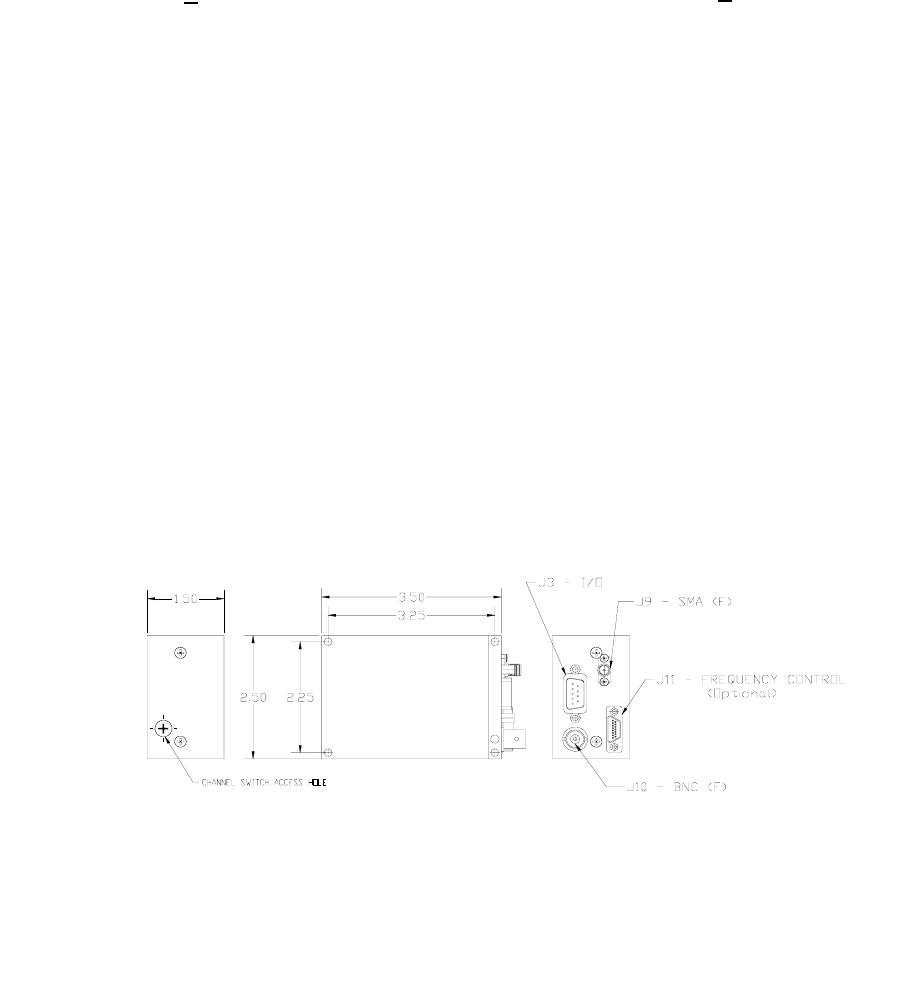
• Dimensions – 1.5 H x 2.5 W x 3.5 L inches • Weight – 6.0 oz.
• Video Input – BNC female • RF Output – SMA female
6.0 Mechanical

Pacific Microwave Research, Inc.
AT-100C3 User’s Manual
© 2003
8
7.0 Connector Pin-out
8.0 Repair
There are no user serviceable parts inside the AT-100C3. Damage to the QC seals on the
transmitter voids the warranty. Should your unit require service, contact Pacific
Microwave Research, Inc. at 760.295.5416 or www.pmicrowave.com to request an RMA
number.
Connector J3 DB-9 Male System I/O
Connector Pinout Data
Pin # Function
1 Lo/Hi Power – Tie to ground for low power
2 Audio 1 Input (HI)
3 Audio 2 Input (HI)
4 Aux Video Input (parallel with J10 BNC)
5 +11 to +14.5 Vdc – Primary power input
6 Ground
7 Audio 1 Input (LO)
8 Audio 2 Input (LO)
9 Ground