Pacific Microwave Research AT100C3 Microwave Video and Audio Transmitter User Manual AT 100C3 User s Manual
Pacific Microwave Research, Inc. Microwave Video and Audio Transmitter AT 100C3 User s Manual
Contents
AT100C3 User Manual

Pacific Microwave Research, Inc.
AT-100 Series
Microwave Video and Audio Transmitter
USER’S MANUAL
Pacific Microwave Research, Inc.
1485 Poinsettia Avenue, Suite 111
Vista, CA 92081
760.295.5416
www.pmicrowave.com
S/N ________________

Pacific Microwave Research, Inc.
AT-100C3 User’s Manual
© 2003
1
1.1 Introduction
The AT-100C3 Microwave Video and Audio Transmitter from Pacific Microwave
Research is a compact transmitter designed for short-range transmission applications
under FCC Part 74, and Part 101. Common uses include law enforcement surveillance
and electronic field production. The AT-100C3 is a compact unit designed for portable
and field applications to transmit remote video to a central receive location. The AT-
100C3 is designed to transmit one NTSC (or PAL) video signal plus two high quality
video signals. The AT-100C3 operates from a 12 Vdc power source and is capable of up
to 2 Watts of output power. The AT-100C3 may be equipped with up to 16 channels
consistent with parameters listed on the user’s FCC station license.
2.0 Operation
The following section describes the proper operating techniques for the AT-100C3
transmitter including power, antenna, video, and audio connections. The AT-100C3
generates heat during normal operation. The user should give careful consideration to
mounting the transmitter in such as way as to insure heat is directed away from the
housing. An external heatsink may be desirable in some operational modes.
2.1 Primary Connections
A number of connections must be made in order for the AT-100C3 to operate properly.
These include dc power; transmit antenna, video input, and audio input.
WARNING
Prior to transmitting, the user should determine the proper frequency or
channel of operation. Operating on the wrong frequency could cause
interference to other licensed users. Part 101 users may coordinate
frequencies through nationally recognized frequency coordination bodies
or through local law enforcement user groups. Part 74 users should contact
their local frequency coordinator or check www.sbe.org for additional
information. Always verify a frequency is not in use before transmitting.

Pacific Microwave Research, Inc.
AT-100C3 User’s Manual
© 2003
2
2.1.1 DC Power Input
The AT-100C3 is designed to operate from a nominal +12 Vdc power source. Power is
supplied through the front panel DB-9M connector (J3) with +12 Vdc on Pin 5 and
Ground on Pin 9. This source should be fused at 2.0 A. The AT-100C3 will operate over
a voltage range of +11 to +14.5 Vdc. Power consumption at the high power setting (2 W)
is nominally 1.2 A. Power consumption at the low power setting (0.5 W) is nominally
0.7 A. The input to the AT-100C3 is internally protected against reverse polarity. The
AT-100C3 transmitter is operating whenever power is applied.
2.1.2 Antenna
The antenna is connected to front panel female SMA connector (J9). Any resonant
antenna is suitable for connection. Antenna type and gain should be determined based
upon the intended application. Only high quality coaxial cable should be used to
interconnect the transmitter and antenna. All SMA connectors should be tightened with
the appropriate 5/16” wrench using approximately 5 in./lbs of torque. MAXIMUM
TORQUE IS 8 IN./LBS. DO NOT OVERTIGHTEN. Thumb tight connections are not
suitable for reliable operation!
2.1.3 Video Input
Video is input to the AT-100C3 through the front panel BNC connector (J10). This
unbalanced input accepts a nominal 1 Vp/p video input. The transmitter may be factory
configured for the NTSC or PAL standard. An NTSC transmitter must be used with an
NTSC receiver. A PAL transmitter must be used with a PAL receiver. Maintenance of
proper video levels is important to prevent over-modulation of the transmitter. High
video levels could potentially cause interference to adjacent channel users. Low video
levels will result in a lack of luminance at the receiver. Proper link performance demands
attention to video levels.
2.1.4 Audio Input
Audio is input to the AT-100C3 through the front panel DB-9M connector (J3).
Typically, the AT-100 is configured for two audio subcarrier channels. Each audio
subcarrier has a balanced input with a nominal impedance of 600 Ω. The AT-100C3 may
be factory configured for line or microphone level inputs. Line level audio is typically 0
dBm and microphone level is typically –50 dBm. Full deviation (+ 75 kHz) on a
transmitter configured for line level input is represented by a signal input level of + 9
dBm at 400 Hz. The input for subcarrier number one is on Pin 2 (+) and Pin 7 (-). The
input for subcarrier number two is on Pin 3 (+) and Pin 8 (-). Unbalanced audio may be
connected to the subcarrier inputs by connecting the high side of the audio source to the
(+) terminals and leaving the (-) terminals unconnected.

Pacific Microwave Research, Inc.
AT-100C3 User’s Manual
© 2003
3
3.0 Power Output
The AT-100C3 is capable of operating at two power levels to fit a variety of operational
scenarios. The high power setting is defaulted with no connection to Pin 1 of J3. The
nominal power output on high power is 2 W. To select low power, Pin 1 of J3 must be
connected to ground. This can be accomplished by placing a jumper in the rear of the
mating connector (Pin 6), by a remote switch, or by an open collector transistor junction.
4.0 Frequency Selection
Frequency selection of the AT-100C3 is accomplished by operation of a 16-position
rotary switch located on the rear panel. Use a small flat blade screwdriver or “tweaker”
tool to operate the switch. Frequencies are programmed into the transmitter in
accordance with the users FCC license parameters. Your radio (S/N ____________) is
programmed as indicated in Table 1.
As an option, users may select the frequency of operation of the AT-100C3 in 1 MHz
steps. This is accomplished by connecting a BCD switch to optional connector J11 in
accordance with the pin-out shown in Table 2. This option is only available to
government users.
CH FREQ MHz
1
2
3
4
5
6
7
8
9
10
11
12
13
14
15
16
PIN MHz
1 1
2 2
3 4
4 8
5 10
6 20
7 40
8 80
9 100
10 200
11 400
12 N/C
13 N/C
14 N/C
15 N/C
Table 1. AT-100 Channel Assignments
Table 2. Remote Frequency Control
Pacific Microwave Research, Inc.
AT-100C3 User’s Manual
© 2003
4
5.0 Specifications
Electrical:
• Frequency Range
o AT 100C3 – 6.4 to 7.1 GHz
• VSWR – Infinite (open or short)
• Modulation – True FM
• Modulation Sense – Positive
• Frequency Stability – +0.002%
• Emphasis – NTSC or PAL
• Spurious/Harmonic Output – > -65 dBc
• Analog or Digital Input filtering options
• Video Input Impedance – 75 Ω unbalanced
• Video Input Response – 10 Hz to 4.5 MHz
• Video Input Sensitivity – 8 MHz/Volt
• Audio – any two between 5.5 to 7.5 MHz
o Phase Lock Loop
o 20 Hz to 20 kHz +1.5 dB
600 Ω Balanced Input
Microphone or Line Level
• Power Output
o High Power – 2.0 W nominal
o Low Power – 0.3 W nominal
Environmental:
• Operating temperature: -10 to +65 °C • Relative Humidity: 0 to 95%, non-
condensing
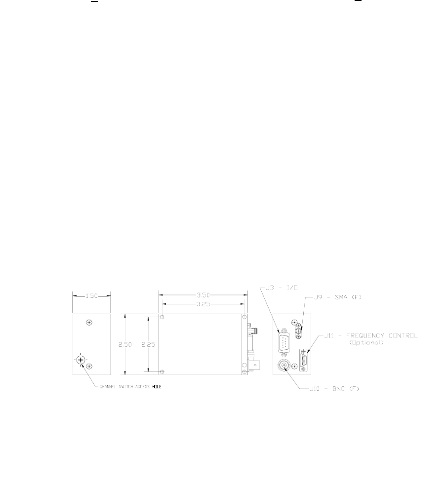
Mechanical:
• 9-pin full function I/O connector • Housing – milled aluminum
• Dimensions – 1.5 H x 2.5 W x 3.5 L inches • Weight – 6.0 oz.
• Video Input – BNC female • RF Output – SMA female
6.0 Mechanical

Pacific Microwave Research, Inc.
AT-100C3 User’s Manual
© 2003
5
7.0 Connector Pin-out
8.0 Repair
There are no user serviceable parts inside the AT-100C3. Damage to the QC seals on the
transmitter voids the warranty. Should your unit require service, contact Pacific
Microwave Research, Inc. at 760.295.5416 or www.pmicrowave.com to request an RMA
number.
Connector J3 DB-9 Male System I/O
Connector Pinout Data
Pin # Function
1 Lo/Hi Power – Tie to ground for low power
2 Audio 1 Input (HI)
3 Audio 2 Input (HI)
4 Aux Video Input (parallel with J10 BNC)
5 +11 to +14.5 Vdc – Primary power input
6 Ground
7 Audio 1 Input (LO)
8 Audio 2 Input (LO)
9 Ground