Packard Bell M3350 Users Manual PB Greenwood AIO SG
M3350 pb_sg_onetwo_l5350_l5351
M3350 to the manual 22280d5b-f95a-4153-b6c6-0ecb6e2edb95
2015-02-03
: Packard-Bell Packard-Bell-M3350-Users-Manual-466936 packard-bell-m3350-users-manual-466936 packard-bell pdf
Open the PDF directly: View PDF ![]() .
.
Page Count: 122 [warning: Documents this large are best viewed by clicking the View PDF Link!]
- Packard Bell oneTwo M3350 / oneTwo M3351 / oneTwo L5350 / oneTwo L5351 All-In-One Computer Service Guide
- Table of Contents
- Features and Specifications
- System Utilities
- System Disassembly
- Disassembly Tools
- Pre-disassembly Procedure
- Disassembly Procedures
- Removing the Computer Stand
- Removing the I/O Cable Cover
- Removing the Rubber Feet
- Removing the Rear Cover
- Removing the I/O Cable Plate
- Removing the Optical Disc Drive
- Removing the Scaler Board
- Removing the USB/Audio Board
- Removing the Wall Mount Plate
- Removing the TV Tuner Card
- Removing the Graphics Card
- Removing the Hard Disk Drive
- Removing the Inverter Board
- Removing the Heat Sink Fan (HSF) Assembly
- Removing the Processor
- Removing the Memory Modules
- Removing the RTC Battery
- Removing the Mainboard
- Removing the Power Supply Unit
- Removing the Touchscreen Control Board
- Removing the Bluetooth Module
- Removing the Power Button Assembly
- Removing the LCD Assembly
- Removing the Main Chassis
- Removing the LCD Cable
- Removing the LCD Board Cover
- Removing the Webcam Module
- Removing the Capacitive LED Board
- Removing the Light Bars
- Troubleshooting
- System Architecture
- Field Replaceable Unit (FRU) List
- Model Definitions and Configurations
- Test Compatible Components
- Online Support Information
- Index

Packard Bell oneTwo M3350 / oneTwo M3351 /
oneTwo L5350 / oneTwo L5351
All-In-One Computer Service Guide
PRINTED IN TAIWAN
Service guide files and updates are available
on the Acer/CSD web site; for more
information, go to http://csd.acer.com.tw

ii Packard Bell oneTwo M3350 / oneTwo M3351 / oneTwo L5350 / oneTwo L5351 Service Guide
Revision History
Refer to the table below for changes made on this version of the Packard Bell oneTwo M3350 / oneTwo M3351 / oneTwo L5350
/ oneTwo L5351 All-In-One Computer Service Guide.
Date Chapter Updates

Packard Bell oneTwo M3350 / oneTwo M3351 / oneTwo L5350 / oneTwo L5351 Service Guide iii
Copyright
Copyright © 2010 by Acer Incorporated. All rights reserved. No part of this publication may be reproduced,
transmitted, transcribed, stored in a retrieval system, or translated into any language or computer language, in
any form or by any means, electronic, mechanical, magnetic, optical, chemical, manual or otherwise, without
the prior written permission of Acer Incorporated.
Disclaimer
The information in this guide is subject to change without notice.
Acer Incorporated makes no representations or warranties, either expressed or implied, with respect to the
contents hereof and specifically disclaims any warranties of merchantability or fitness for any particular
purpose. Any Acer Incorporated software described in this guide is sold or licensed "as is". Should the
programs prove defective following their purchase, the buyer (and not Acer Incorporated, its distributor, or its
dealer) assumes the entire cost of all necessary servicing, repair, and any incidental or consequential
damages resulting from any defect in the software.
Acer is a registered trademark of Acer Incorporated.
Other brand and product names are trademarks and/or registered trademarks of their respective holders.

iv Packard Bell oneTwo M3350 / oneTwo M3351 / oneTwo L5350 / oneTwo L5351 Service Guide
Conventions
The following textual conventions are used in this service guide.
SCREEN MESSAGES Denotes actual messages that appear on screen.
NOTE Gives additional information related to the current topic.
WARNING Alerts you to any physical risk or system damage that might result from
doing or not doing specific actions.
CAUTION Gives precautionary measures to avoid possible hardware or software
problems.
IMPORTANT Reminds you to do specific actions relevant to the accomplishment of
procedures.

Packard Bell oneTwo M3350 / oneTwo M3351 / oneTwo L5350 / oneTwo L5351 Service Guide v
Service Guide Coverage
This Service Guide provides you with all technical information relating to the BASIC CONFIGURATION
decided for our "global" product offering. To better fit local market requirements and enhance product
competitiveness, your regional office MAY have decided to extend the functionality of a machine (e.g. add-on
card, modem, or extra memory capability). These LOCALIZED FEATURES will NOT be covered in this generic
service guide. In such cases, please contact your regional offices or the responsible personnel/channel to
provide you with further technical details.
FRU Information
Please note WHEN ORDERING FRU PARTS, that you should check the most up-to-date information available
on your regional web or channel. If, for whatever reason, a part number change is made, it will not be noted in
the printed service guide. For AUTHORIZED SERVICE PROVIDERS, your office may have a DIFFERENT
part number code to those given in the FRU list of this printed service guide. You MUST use the list provided
by your regional Acer office to order FRU parts for repair and service of customer machines.

vi Packard Bell oneTwo M3350 / oneTwo M3351 / oneTwo L5350 / oneTwo L5351 Service Guide

vii Packard Bell oneTwo M3350 / oneTwo M3351 / oneTwo L5350 / oneTwo L5351 Service Guide
Chapter 1 – Features and Specifications . . . . . . . . . . . . . . . . . . . . . . . 1
System Features . . . . . . . . . . . . . . . . . . . . . . . . . . . . . . . . . . . . . . . . . . . . . . . . . . . . . .1
Physical Specifications . . . . . . . . . . . . . . . . . . . . . . . . . . . . . . . . . . . . . . . . . . . . . . . . . .2
System Tour . . . . . . . . . . . . . . . . . . . . . . . . . . . . . . . . . . . . . . . . . . . . . . . . . . . . . . . . . .3
Front View . . . . . . . . . . . . . . . . . . . . . . . . . . . . . . . . . . . . . . . . . . . . . . . . . . . . . . .3
Left View . . . . . . . . . . . . . . . . . . . . . . . . . . . . . . . . . . . . . . . . . . . . . . . . . . . . . . . .4
Right View . . . . . . . . . . . . . . . . . . . . . . . . . . . . . . . . . . . . . . . . . . . . . . . . . . . . . . .5
Rear View . . . . . . . . . . . . . . . . . . . . . . . . . . . . . . . . . . . . . . . . . . . . . . . . . . . . . . . .6
Hardware Specifications . . . . . . . . . . . . . . . . . . . . . . . . . . . . . . . . . . . . . . . . . . . . . . . . .7
Processor . . . . . . . . . . . . . . . . . . . . . . . . . . . . . . . . . . . . . . . . . . . . . . . . . . . . . . . .7
Chipsets . . . . . . . . . . . . . . . . . . . . . . . . . . . . . . . . . . . . . . . . . . . . . . . . . . . . . . . .7
BIOS . . . . . . . . . . . . . . . . . . . . . . . . . . . . . . . . . . . . . . . . . . . . . . . . . . . . . . . . . . . .7
Memory . . . . . . . . . . . . . . . . . . . . . . . . . . . . . . . . . . . . . . . . . . . . . . . . . . . . . . . . .8
Hard Disk Drive . . . . . . . . . . . . . . . . . . . . . . . . . . . . . . . . . . . . . . . . . . . . . . . . . . .8
Optical Disc Drive . . . . . . . . . . . . . . . . . . . . . . . . . . . . . . . . . . . . . . . . . . . . . . . . . .8
Ethernet . . . . . . . . . . . . . . . . . . . . . . . . . . . . . . . . . . . . . . . . . . . . . . . . . . . . . . . . .9
Wireless LAN . . . . . . . . . . . . . . . . . . . . . . . . . . . . . . . . . . . . . . . . . . . . . . . . . . . . .9
Bluetooth . . . . . . . . . . . . . . . . . . . . . . . . . . . . . . . . . . . . . . . . . . . . . . . . . . . . . . . .9
Audio . . . . . . . . . . . . . . . . . . . . . . . . . . . . . . . . . . . . . . . . . . . . . . . . . . . . . . . . . . .9
Webcam . . . . . . . . . . . . . . . . . . . . . . . . . . . . . . . . . . . . . . . . . . . . . . . . . . . . . . . .9
LCD Panel . . . . . . . . . . . . . . . . . . . . . . . . . . . . . . . . . . . . . . . . . . . . . . . . . . . . . .10
Power Supply Unit . . . . . . . . . . . . . . . . . . . . . . . . . . . . . . . . . . . . . . . . . . . . . . . .10
Chapter 2 – System Utilities . . . . . . . . . . . . . . . . . . . . . . . . . . . . . . . . . 11
CMOS Setup Utility . . . . . . . . . . . . . . . . . . . . . . . . . . . . . . . . . . . . . . . . . . . . . . . . . . .11
Accessing the Setup Utility . . . . . . . . . . . . . . . . . . . . . . . . . . . . . . . . . . . . . . . . . .12
Navigating through the Setup Utility . . . . . . . . . . . . . . . . . . . . . . . . . . . . . . . . . . .13
Setup Utility Menus . . . . . . . . . . . . . . . . . . . . . . . . . . . . . . . . . . . . . . . . . . . . . . .13
Chapter 3 – System Disassembly . . . . . . . . . . . . . . . . . . . . . . . . . . . . . 25
Disassembly Tools . . . . . . . . . . . . . . . . . . . . . . . . . . . . . . . . . . . . . . . . . . . . . . . . . . . .25
Pre-disassembly Procedure . . . . . . . . . . . . . . . . . . . . . . . . . . . . . . . . . . . . . . . . . . . . . .25
Disassembly Procedures . . . . . . . . . . . . . . . . . . . . . . . . . . . . . . . . . . . . . . . . . . . . . . . .26
Removing the Computer Stand . . . . . . . . . . . . . . . . . . . . . . . . . . . . . . . . . . . . . .26
Removing the I/O Cable Cover . . . . . . . . . . . . . . . . . . . . . . . . . . . . . . . . . . . . . . .27
Removing the Rubber Feet . . . . . . . . . . . . . . . . . . . . . . . . . . . . . . . . . . . . . . . . . .27
Removing the Rear Cover . . . . . . . . . . . . . . . . . . . . . . . . . . . . . . . . . . . . . . . . . . .28
Removing the I/O Cable Plate . . . . . . . . . . . . . . . . . . . . . . . . . . . . . . . . . . . . . . . .28
Removing the Optical Disc Drive . . . . . . . . . . . . . . . . . . . . . . . . . . . . . . . . . . . . . .29
Removing the Scaler Board . . . . . . . . . . . . . . . . . . . . . . . . . . . . . . . . . . . . . . . . . .31
Removing the USB/Audio Board . . . . . . . . . . . . . . . . . . . . . . . . . . . . . . . . . . . . . .33
Removing the Wall Mount Plate . . . . . . . . . . . . . . . . . . . . . . . . . . . . . . . . . . . . . .35
Removing the TV Tuner Card . . . . . . . . . . . . . . . . . . . . . . . . . . . . . . . . . . . . . . . .36
Removing the Graphics Card . . . . . . . . . . . . . . . . . . . . . . . . . . . . . . . . . . . . . . . .37
Removing the Hard Disk Drive . . . . . . . . . . . . . . . . . . . . . . . . . . . . . . . . . . . . . . .40
Removing the Inverter Board . . . . . . . . . . . . . . . . . . . . . . . . . . . . . . . . . . . . . . . .42
Removing the Heat Sink Fan (HSF) Assembly . . . . . . . . . . . . . . . . . . . . . . . . . . . . .43
Removing the Processor . . . . . . . . . . . . . . . . . . . . . . . . . . . . . . . . . . . . . . . . . . . .44
Removing the Memory Modules . . . . . . . . . . . . . . . . . . . . . . . . . . . . . . . . . . . . . .46
Removing the RTC Battery . . . . . . . . . . . . . . . . . . . . . . . . . . . . . . . . . . . . . . . . . .46
Removing the Mainboard . . . . . . . . . . . . . . . . . . . . . . . . . . . . . . . . . . . . . . . . . . .47
Table of Contents

Packard Bell oneTwo M3350 / oneTwo M3351 / oneTwo L5350 / oneTwo L5351 Service Guide viii
Removing the Power Supply Unit . . . . . . . . . . . . . . . . . . . . . . . . . . . . . . . . . . . . .49
Removing the Touchscreen Control Board . . . . . . . . . . . . . . . . . . . . . . . . . . . . . .51
Removing the Bluetooth Module . . . . . . . . . . . . . . . . . . . . . . . . . . . . . . . . . . . . .52
Removing the Power Button Assembly . . . . . . . . . . . . . . . . . . . . . . . . . . . . . . . . .53
Removing the LCD Assembly . . . . . . . . . . . . . . . . . . . . . . . . . . . . . . . . . . . . . . . .54
Removing the Main Chassis . . . . . . . . . . . . . . . . . . . . . . . . . . . . . . . . . . . . . . . . .56
Removing the LCD Cable . . . . . . . . . . . . . . . . . . . . . . . . . . . . . . . . . . . . . . . . . . .58
Removing the LCD Board Cover . . . . . . . . . . . . . . . . . . . . . . . . . . . . . . . . . . . . .58
Removing the Webcam Module . . . . . . . . . . . . . . . . . . . . . . . . . . . . . . . . . . . . .59
Removing the Capacitive LED Board . . . . . . . . . . . . . . . . . . . . . . . . . . . . . . . . . .59
Removing the Light Bars . . . . . . . . . . . . . . . . . . . . . . . . . . . . . . . . . . . . . . . . . . .60
Chapter 4 – Troubleshooting . . . . . . . . . . . . . . . . . . . . . . . . . . . . . . . . 61
Hardware Diagnostic Procedure . . . . . . . . . . . . . . . . . . . . . . . . . . . . . . . . . . . . . . . . . .61
System Check Procedures . . . . . . . . . . . . . . . . . . . . . . . . . . . . . . . . . . . . . . . . . . .61
Checkpoints . . . . . . . . . . . . . . . . . . . . . . . . . . . . . . . . . . . . . . . . . . . . . . . . . . . . .62
POST Error Indicators . . . . . . . . . . . . . . . . . . . . . . . . . . . . . . . . . . . . . . . . . . . . . .66
BIOS Recovery . . . . . . . . . . . . . . . . . . . . . . . . . . . . . . . . . . . . . . . . . . . . . . . . . . . . . . .77
Clearing CMOS . . . . . . . . . . . . . . . . . . . . . . . . . . . . . . . . . . . . . . . . . . . . . . . . . . . . . .78
Chapter 5 – System Architecture . . . . . . . . . . . . . . . . . . . . . . . . . . . . . 79
Block Diagram . . . . . . . . . . . . . . . . . . . . . . . . . . . . . . . . . . . . . . . . . . . . . . . . . . . . . . .79
Mainboard Layout . . . . . . . . . . . . . . . . . . . . . . . . . . . . . . . . . . . . . . . . . . . . . . . . . . . .80
Chapter 6 – Field Replaceable Unit (FRU) List . . . . . . . . . . . . . . . . . . . 83
Exploded Diagram . . . . . . . . . . . . . . . . . . . . . . . . . . . . . . . . . . . . . . . . . . . . . . . . . . . .84
FRU List . . . . . . . . . . . . . . . . . . . . . . . . . . . . . . . . . . . . . . . . . . . . . . . . . . . . . . . . . . . .85
Appendix A – Model Definitions and Configurations . . . . . . . . . . . . 94
Appendix B – Test Compatible Components . . . . . . . . . . . . . . . . . . . . 100
Approved Vendor List (AVL) . . . . . . . . . . . . . . . . . . . . . . . . . . . . . . . . . . . . . . . . . . . .102
Appendix C – Online Support Information . . . . . . . . . . . . . . . . . . . . . 110
Index . . . . . . . . . . . . . . . . . . . . . . . . . . . . . . . . . . . . . . . . . . . . . 111
Table of Contents

Packard Bell oneTwo M3350 / oneTwo M3351 / oneTwo L5350 / oneTwo L5351 Service Guide 1
This chapter lists the features and specifications of the Packard Bell oneTwo M3350 / oneTwo M3351 /
oneTwo L5350 / oneTwo L5351 AIO computer.
System Features
NOTE The items listed in this section are for reference only. The exact configuration of your PC depends
on the model purchased.
Component Description
Processor • Socket AM3, 941 pin contacts
• Supports the AMD Phenom™ II X3 or X4 Processors
Chipset nVIDIA GeForce 8200 (MCP78PV)
Memory • Number of DIMM slots: Four DDR3 DIMM slots
• Maximum memory: 8 GB (using four 2 GB modules)
PCI expansion options • One PCI Express x16 slot (for graphics card installation)
• One PCI Express x1 slot (for TV tuner card installation)
Display • ZX6350: 21.5-inch LCD panel
• ZX6351: 21.5-inch LCD touchscreen panel
• ZX4350: 23-inch LCD panel
• ZX4351: 23-inch LCD touchscreen panel
Audio • Two built-in 5W stereo speakers
• Realtek ALC888S 7.1+2 Channel High Definition Audio Codec
I/O ports • Right panel
– USB ports (two)
– Headphone jack
– Microphone jack
• Left panel
– HD dual digital TV tuner (optional)
– PS/2 keyboard and mouse ports
– Line-in, line-out, and microphone jacks
– Line-in and line-out jacks
– USB ports (four)
– eSATA port
– Ethernet jack (RJ-45)
– External display (VGA) port
– Serial-to-DVI port (optional)
– HDMI port
– PS/2 keyboard and mouse ports
Media storage • 3.5-inch 25.4 mm 5400/7200 rpm SATA hard disk drive (HDD)
• Slim type SATA optical disc drive (ODD)
Card reader • 9-in-1 card reader slot
• Supports MultiMediaCard (MMC), Reduced-Size MultiMediaCard
(RS-MMC), Secure Digital (SD), xD-Picture Card (xD), Secure Digital
High Capacity (SDHC), Memory Stick (MS), Memory Stick PRO
(MS PRO) cards, CompactFlash Type I and II (CF-I, CF-II), and
microdrives
Features and Specifications
Chapter 1

2 Packard Bell oneTwo M3350 / oneTwo M3351 / oneTwo L5350 / oneTwo L5351 Service Guide
Physical Specifications
Connectivity • Wired LAN: Onboard 10/100/1000 Ethernet support
• WLAN option: Mini Card wireless network adapter (802.11 b/g/n)
• WPAN option: Bluetooth® 2.1+EDR (Enhanced Data Rate)
• Integrated 2.0 MP webcam
Power supply 220 W power supply unit with PFC or non-PFC option (power factor
correction)
Operating system support • Microsoft Windows 7 (Home Premium x64/x86, Home Basic x86)
•FreeDOS
• Linux LL95
Antivirus software Norton Internet Security
Security • BIOS-based user and supervisor passwords
• Kensington lock
Power management ACPI 2.0-compliant
Aspect Description
System dimension (W × H × D) 107 × 445 × 560 mm (4.21 × 17.52 × 22.05 in)
Mainboard form factor Standard DTX
Mainboard dimensions (W × H) 200 × 244 mm
Component Description
Packard Bell oneTwo M3350 / oneTwo M3351 / oneTwo L5350 / oneTwo L5351 Service Guide 3
System Tour
The pictures and tables in this section illustrate the physical outlook of the computer.
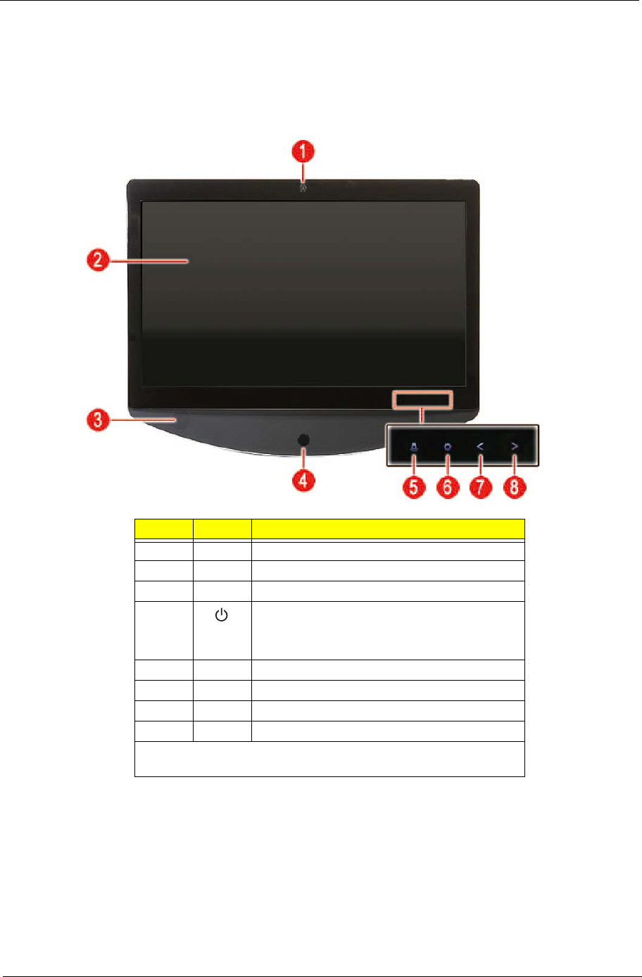
Front View
Item Icon Component
1Integrated webcam
2Display screen
3Speakers
4Power button/indicator
• Blue – System is in power-on mode
• Flashing blue – System is in standby mode
5Auxiliary lighting capacitive key
6LCD brightness capacitive key
7Decrease volume capacitive key
8Increase volume capacitive key
NOTE: Icons for the capacitive keys are only visible when the system
is turned on.
4 Packard Bell oneTwo M3350 / oneTwo M3351 / oneTwo L5350 / oneTwo L5351 Service Guide
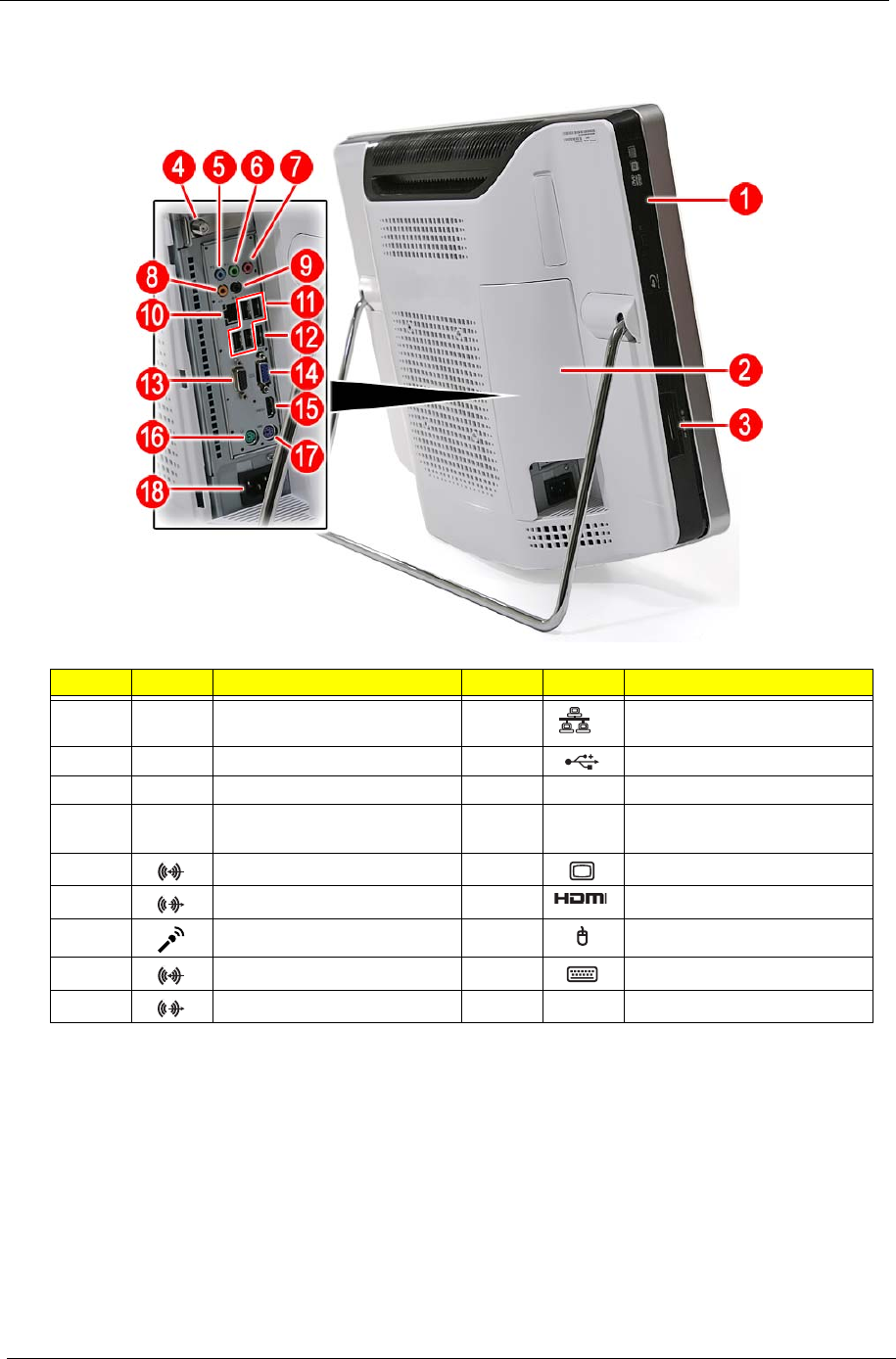
Left View
Item Icon Component Item Icon Component
1Optical disc drive (ODD) 10 Ethernet port (RJ-45)
2I/O cable cover 11 USB ports
39-in-1 card reader 12 eSATA port
4HD dual digital TV tuner
(optional)
13 Serial-to-DVI port (optional)
5Line-in jack 14 Monitor port
6Line-out jack 15 HDMI port
7Microphone jack 16 PS/2 mouse port
8Line-in jack 17 PS/2 keyboard port
9Line-out jack 18 AC power jack
Packard Bell oneTwo M3350 / oneTwo M3351 / oneTwo L5350 / oneTwo L5351 Service Guide 5
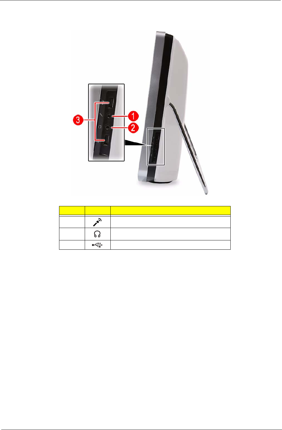
Right View
Item Icon Component
1Microphone jack
2Line-out jack
3USB ports
6 Packard Bell oneTwo M3350 / oneTwo M3351 / oneTwo L5350 / oneTwo L5351 Service Guide
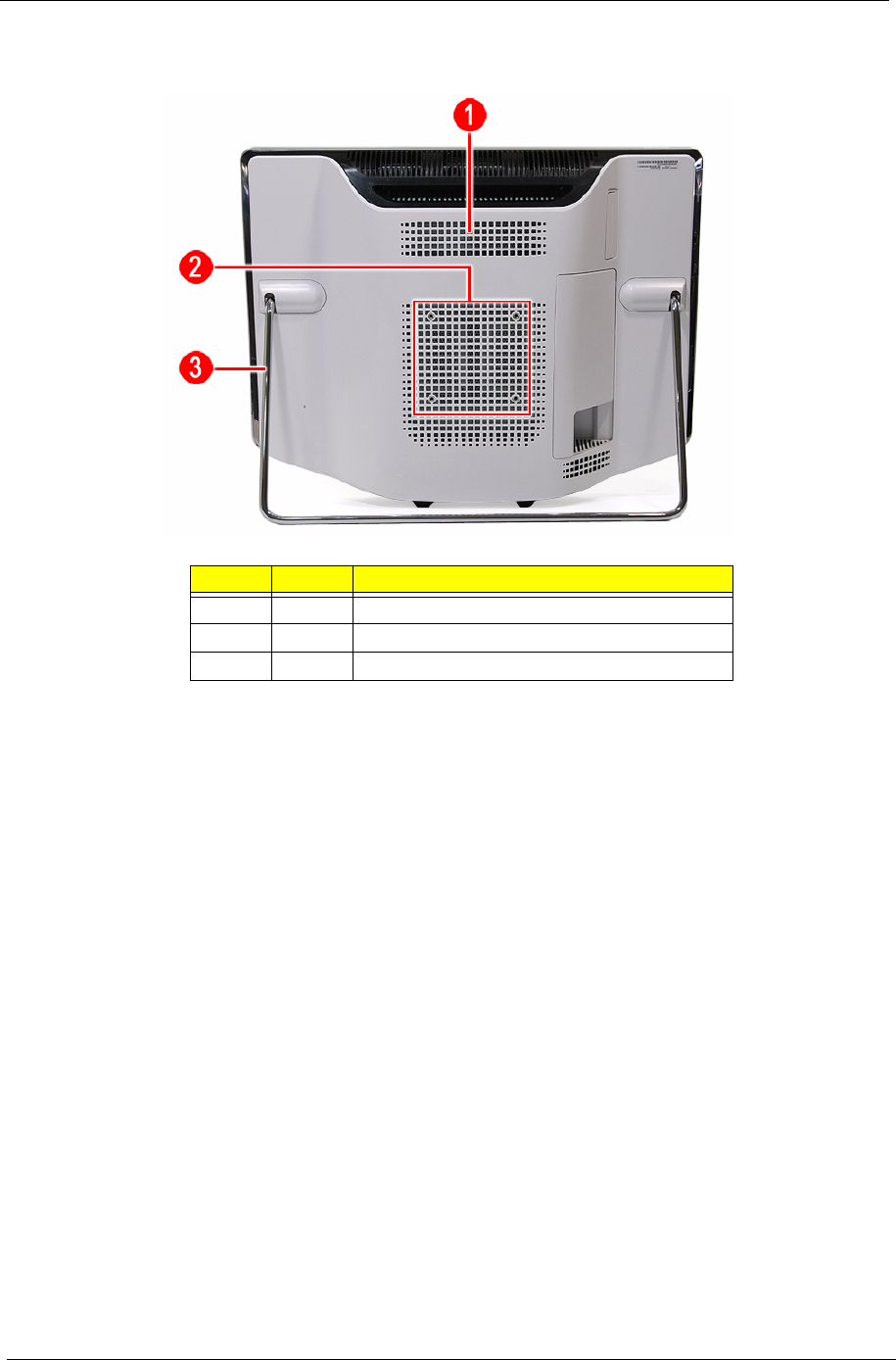
Rear View
Item Icon Component
1Ventilation slots
2Mounting holes for wall mount option
3Computer stand
Packard Bell oneTwo M3350 / oneTwo M3351 / oneTwo L5350 / oneTwo L5351 Service Guide 7
Hardware Specifications
Processor
AMD Phenom II Processors
AMD Athlon II Processors
Chipsets
BIOS
Item Specification
Series X3 X4
Model 700e 705e 900e 910e
Frequency 2.4 GHz 2.5 GHz 2.4 GHz 2.5 GHz
# of cores 3 3 4 4
L2 cache 1.5 MB 1.5 MB 2 MB 2 MB
L3 cache 6 MB 6 MB 6 MB 6 MB
Package type 45 nm 45 nm 45 nm 45 nm
Socket Socket AM3 Socket AM3 Socket AM3 Socket AM3
Max TDP 65 W 65 W 65 W 65 W
Item Specification
Series X2 X3 X4
Model 215 240 245 405e 600e 605e
Frequency 2.7 GHz 2.8 GHz 2.9 GHz 2.3 GHz 2.2 GHz 2.3 GHz
# of cores 2 2 2 3 4 4
L2 cache 1 MB 2 MB 2 MB 1.5 MB 2 MB 2 MB
Package type 45 nm 45 nm 45 nm 45 nm 45 nm 45 nm
Socket Socket AM3 Socket AM3 Socket AM3 Socket AM3 Socket AM3 Socket AM3
Max TDP 65 W 65 W 65 W 45 W 45 W 45 W
Item Specification
System chipset nVIDIA GeForce 8200 (MCP78PV)
I/O controller SIO ITE 8720
Item Specification
BIOS chip AMI BIOS
Setup utility CMOS Setup Utility
8 Packard Bell oneTwo M3350 / oneTwo M3351 / oneTwo L5350 / oneTwo L5351 Service Guide
Memory
Hard Disk Drive
Optical Disc Drive
Item Specification
Controller Integrated in the AMD processor
Number of DIMM slot 4
Maximum memory 8 GB (using four 2 GB modules)
Data rate 1333 MT/s
Supported capacities 1 or 2 GB
DIMM type 240-pin DDR3 SO-DIMM
Supported brands A-Data, Apacer, Kingston, Transcend, Unifosa, Samsung
Population rule You can install memory modules in any combination as long as they match the above
specifications.
Item Specification
Controller Integrated in the nVIDIA GeForce 8200 (MCP78PV)
Form factor 3.5-inch 9.5 mm
Interface SATA 2.0
Supported capacities
320 GB • Seagate Pharaoh (7200 rpm)
• HGST HDT721032SLA380 (7200 rpm)
• WD WD1600AAJS-22L7 (7200 rpm)
500 GB • WD WD5000AAKS-22M9A0 (7200 rpm)
640 GB • Seagate ST3640623AS (7200 rpm)
• HGST HDT721064SLA360 (7200 rpm)
• WD WD6400AAKS-22A7B2 (7200 rpm)
1 TB • Seagate ST31000528AS (7200 rpm)
• HGST HDT721010SLA360 (7200 rpm)
• WD WD10EADS-22M4B0 (5400 rpm) / WD1001FALS-22J7B0 (7200 rpm)
1.5 TB • Seagate ST31500341AS (7200 rpm)
• WD WD15EADS-22P8B0 (5400 rpm)
Item Specification
Controller Integrated in the nVIDIA GeForce 8200 (MCP78PV)
Type DVD-Super Multi double-layer or Blu-ray Disc combo drive option
Form factor Slim type
Tray height (mm)) 12.7 mm
Interface SATA
Supported models
DVD-Super Multi
double-layer drive
•HLDS GT31N
• PLDS DS-8A5SH
Blu-ray Disc
combo drive
• Panasonic UJ141AL/UJ240A
• HLDS CT21N

Packard Bell oneTwo M3350 / oneTwo M3351 / oneTwo L5350 / oneTwo L5351 Service Guide 9
Ethernet
Wireless LAN
Bluetooth
Audio
Webcam
Item Specification
Controller Marvell 88E1116 Intel WG82567V Gigabit NIC
LAN protocol 10/100/1000 Mbps
LAN connector type RJ-45
Item Specification
Model Lite-On WN6607LH
Protocol 802.11 b/g/n
Form factor PCIe Mini Card
Item Specification
Model • Lite-On WB111C-C1
• Xavi BC10B-04C1
Version Bluetooth 2.1 + EDR
Item Specification
Controller Realtek ALC888S 7.1+2 Channel High Definition Audio Codec
Features • Two built-in 5W stereo speakers
• Right panel audio jacks
– Headphone jack
– Microphone jack
• Left panel audio jacks
– Line-in, line-out, and microphone jacks
– Line-in and line-out jacks
Item Specification
Resolution 2.0 MP
Supported models • Chicony CNFA21321004590L
• Park Orchid C04PL037F
• Primax 50-704A4WNT8

10 Packard Bell oneTwo M3350 / oneTwo M3351 / oneTwo L5350 / oneTwo L5351 Service Guide
LCD Panel
Power Supply Unit
Item Specification
Model ZX6350 and ZX6351 ZX4350 and ZX4351
Screen size (diagonal, inch) 21.5-inch 23-inch
Type Wide XGA
Resolution 1920 × 1080
Backlight CCFL
Interface LVDS
Brightness (typical) 300 nits
Display colors 16.7M
Aspect ratio 16:9
Contrast ratio 1000:1
Response time (typical) 5 ms
Touchscreen • ZX6350: Yes
• ZX6351: No
• ZX4350: Yes
• ZX4351: No
Surface treatment AG type, 3H hard coating, Haze 25
Supported models •• LG LM230WF1
• Samsung LTM230HT01
• E-Turbo SR-230M182235D1 (touch
panel)
Inverter board •• Darfon VZ.13156.B01
• Sumida IV30260SPEC139
Item Specification
Output (max.) 220 W
Supported models • Lite-On PS-5221-06A1 / PE-5221-08AP / PS-5221-9AE
• Delta DPS-220UB-1 A / DPS-220UB A / DPS-220UB-2 B
• Chicony CPB09-D220R / CPB09-D220A / CPB09-D220E

Packard Bell oneTwo M3350 / oneTwo M3351 / oneTwo L5350 / oneTwo L5351 Service Guide 11
CMOS Setup Utility
CMOS Setup Utility is a hardware configuration program built into the system ROM. Since most systems are
already properly configured and optimized, there is normally no need to run this utility.
You will need to run this utility under the following conditions:
• When changing the system configuration including:
• Setting the system time and date
• Configuring the system drives and peripherals
• Specifying the boot device sequence
• Configuring the power management modes
• Setting up system passwords or making other changes to the security setup
• When trying to resolve IRQ conflicts
• When a configuration error is detected by the system and you are prompted ("Run Setup" message) to
make changes to the BIOS settings.
The Setup Utility loads the configuration values in a battery-backed nonvolatile memory called CMOS RAM.
This memory area is not part of the system RAM, which allows configuration data to be retained when power is
turned off. The values take effect when the system is booted. POST uses these values to configure the
hardware. If the values and the actual hardware do not agree, POST generates an error message. You must
run this utility to change the hardware settings from the default or current configuration.
IMPORTANT If you repeatedly receive “Run Setup” messages, the RTC battery located on the mainboard
(BT1) may be defective. In this case, the system cannot retain configuration values in CMOS.
Replace the RTC battery with a new one.
NOTE For ease of reading, CMOS Setup Utility will be simply referred to as “Setup” or “Setup Utility” in this
Service Guide.
System Utilities
Chapter 2
12 Packard Bell oneTwo M3350 / oneTwo M3351 / oneTwo L5350 / oneTwo L5351 Service Guide
Accessing the Setup Utility
1. Turn on the computer.
If the computer is already turned on, save your data and close all open applications, then restart the
computer.
2. During POST, press Delete.
If you fail to press Delete before POST is completed, you will need to restart the computer.
Use the Up/Down/Left/Right arrow keys to move between the menu options, then press Enter to execute that
option.
Some options lead to pop-up dialog boxes that prompt you to verify that you wish to execute that option. Other
options lead to dialog boxes that prompt you for information.
Some options (marked with a ) lead to submenus that enable you to change the values for the option. Use
the Up/Down/Left/Right arrow keys to scroll through the items in the submenu

Packard Bell oneTwo M3350 / oneTwo M3351 / oneTwo L5350 / oneTwo L5351 Service Guide 13
Navigating through the Setup Utility
Use the keys listed in the legend bar on the bottom of the Setup screen to work your way through the various
menu and submenu screens of the Setup Utility. The table below lists these legend keys and their respective
functions.
Setup Utility Menus
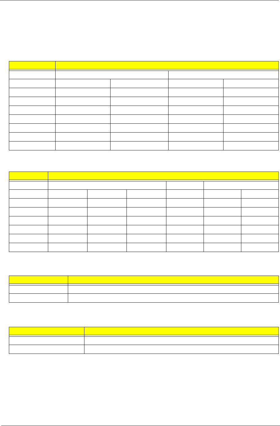
The Setup Utility has twelve menus for configuring the various system functions. These include:
Key Function
Up/Down/Left/
Right arrow keys
Move the cursor to the menu/field you want.The currently selected field will be highlighted.
Enter • To open the page for the currently selected menu/submenu
• To apply a field value.
PgUp and PgDn Move the cursor to the previous and next page of a multipage menu.
Home Move the cursor to the first page of a multipage menu.
End Move the cursor to the last page of a multipage menu.
+ and - To select a value for the currently selected field (only if it is user-configurable). Press these
keys repeatedly to display all possible entries. A parameter that is enclosed in square
brackets [ ] is user-configurable. Grayed-out parameters are not user-configurable for one
of the following reasons:
• The field value is auto-configured or auto-detected.·
• The field value is informational only.
• The field is password-protected.
Esc If you press this key:
• On one of the primary menu screens, the Exit menu displays.
• On a submenu screen, the previous screen displays.
• When you are making selections from a pop-up menu, closes the pop-up without making
a selection.
F1 To bring up the General Help window. The General Help window describes other Setup
navigation keys that are not displayed on the legend bar.
F9 Press to load default system values.
F10 Press to save changes and close the Setup Utility.
• Product Information
• Standard CMOS Features
• Advanced BIOS Features
• Advanced Chipset Features
• Integrated Peripherals
• Power Management Setup
• PC Health Status
• Frequency/Voltage Control
• BIOS Security Features
• Load Default Settings
• Save & Exit Setup
• Exit Without Saving
NOTES • The screenshots used in this section are for illustration only. The values displayed may not be
the same as those in your computer.
• In the descriptive tables following each of the menu screen illustrations, settings in boldface are
the default and suggested settings.
14 Packard Bell oneTwo M3350 / oneTwo M3351 / oneTwo L5350 / oneTwo L5351 Service Guide
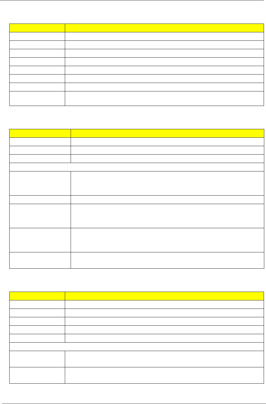
Product Information
.
Field Description
Processor Type Type of processor installed on the system
Processor Speed Speed of the processor installed on the system
System Memory Size of system memory detected during boot-up
Product Name Official model name of the computer.
System Serial Number System serial number.
System BIOS Version Current system BIOS version
BIOS Release Date Date when the CMOS setup utility was released.
Asset Tag Number System asset tag number
Packard Bell oneTwo M3350 / oneTwo M3351 / oneTwo L5350 / oneTwo L5351 Service Guide 15
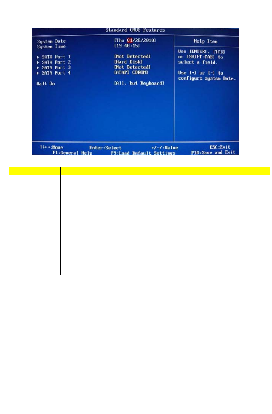
Standard CMOS Features
Field Description Value
System Date Sets the system date. MM/DD/YYYY
(month/day/year)
System Time Sets the system time. HH:MM:SS
(hour:minute:second)
AHCI Port 1–4 Your computer supports four SATA channels, each channel allows one SATA device to be
installed. Press Enter to display the individual configuration screen of installed SATA
drive(s).
Halt On Determines whether the system will stop for an error during the
POST. Options include:
• All Errors - Any error detected will pause the system.
• No Errors - BIOS will ignore any errors detected during
POST
• All, but Keyboard - If a keyboard error is detected, BIOS will
pause the system.
All Errors
No Errors
All, But Keyboard
16 Packard Bell oneTwo M3350 / oneTwo M3351 / oneTwo L5350 / oneTwo L5351 Service Guide
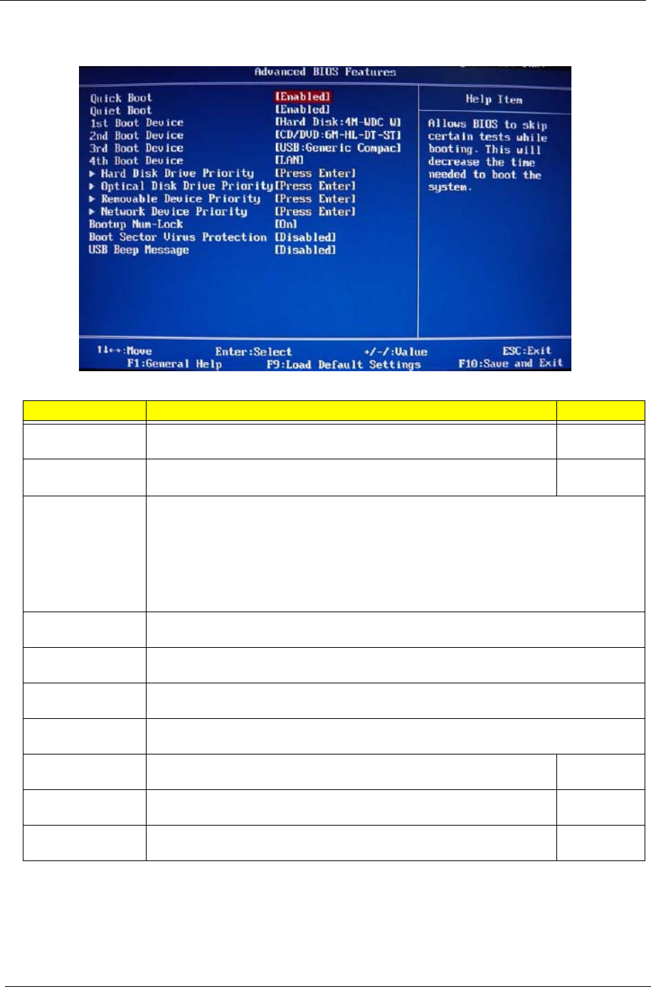
Advanced BIOS Features
Field Description Value
Quick Boot When enabled, the system starts up more quickly be elimination some of
the POST routines. Enabled
Disabled
Quiet Boot When enabled, BIOS will show a full screen logo when booting; if
disabled, BIOS will show the diagnostic POST screen when booting. Enabled
Disabled
1st/2nd/3rd/4th
Boot Device
Displays the device assigned to the specified boot sequence. The Setup Utility attempts
to boot the operating system in this order. By default, the computer searches for boot
devices in the following order:
• Hard disk
• Optical drive (CD/DVD)
• Removable device
• Network boot (LAN)
Hard Disk Drive
Priority
Press Enter to specify the boot device priority sequence for the installed hard drive(s).
Optical Disk Drive
Priority
Press Enter to specify the boot device priority sequence for the installed optical drive.
Removable Device
Priority
Press Enter to specify the boot device priority sequence for removable drives.
Network Device
Priority
Press Enter to specify the boot device priority sequence foe available network drives.
Bootup Num-Lock If you set this item to On, the keyboard Num Lock key will be active when
the computer boots up. On
Off
Boot Sector Virus
Protection
If set to Disabled, when anything attempts to access the boot sector or
hard disk partition table, there will be no warning message.
Enabled
Disabled
USB Beep
Message
Select whether to allow the BIOS to emit error beeps or display error
messages during USB device enumeration.
Enabled
Disabled
Packard Bell oneTwo M3350 / oneTwo M3351 / oneTwo L5350 / oneTwo L5351 Service Guide 17
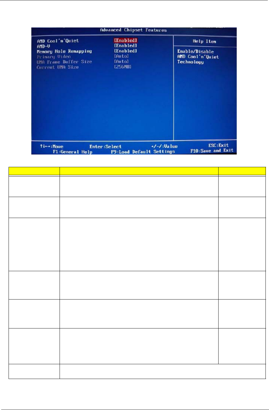
Advanced Chipset Features
Field Description Value
AMD Cool ’n’
Quiet
Select whether to enable the AMD Cool 'N' Quiet Technology. This
technology allows a compliant OS to dynamically adjust the system
voltage and core frequency for reduced heat and noise emission.
Enabled
Disabled
AMD-V Select whether to enable the AMD-V Technology. This technology
allows a single platform to run multiple operating systems in
independent partitions.
Enabled
Disabled
Memory Hole
Remapping
When enabled, some or all of the memory between the 2 GB and
4 GB limits to addresses above 4 GB. This is a workaround for the
PCI hole or PCI memory hole which is a limitation of 32-bit hardware
and 32-bit operating systems that causes a computer to appear to
have less memory available than is physically installed.
Note: This feature is useful for systems running on 64-bit OS and
those 32-bit systems that support the Physical Address Extension
method.
Enabled
Disabled
Hybrid SLI Select whether to enable the Hybrid SLI technology when a nVIDIA
graphics card is installed. Hybrid SLI increases graphics
performance with GeForce® Boost and provides intelligent power
management with HybridPower™.
Enabled
Disabled
Primary Video When a graphics card is installed, you have the option to select
which graphics controller to activate.
Note: When this field is set to Auto, the graphics controller priority
sequence is: PCIE, Onboard, then PCI.
Auto
PCIE
Onboard
PCI
UMA Frame Buffer
Size
When a graphics card is installed, you can select how the system
video memory (frame buffer) is allotted. Auto
32 MB
64 MB
128 MB
256 MB
Current UMA Size Displays the size of video memory (located in upper memory area–UMA) detected during
boot-up.
18 Packard Bell oneTwo M3350 / oneTwo M3351 / oneTwo L5350 / oneTwo L5351 Service Guide
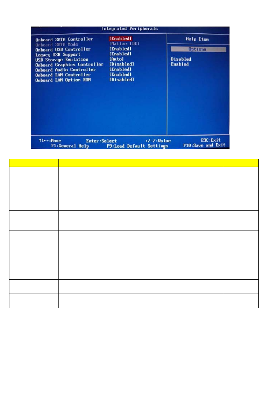
Integrated Peripherals
Field Description Value
Onboard SATA
Controller
Enables or disables the onboard SATA controller. Enabled
Disabled
Onboard SATA
Mode
Set the operating mode for the onboard SATA controller. Native IDE
Onboard USB
Controller
Enables or disables the onboard USB controller. Enabled
Disabled
Legacy USB
Support
Enables or disables support for a USB mouse and USB keyboard. When
enabled, any attached USB mouse or USB keyboard can control the
system even when there is no USB driver loaded onto the system.
Enabled
Disabled
USB Storage
Emulation
If set to Auto, a USB devices with a capacity of equal or less than 2 GB
will be emulated as a bootable floppy disk. Auto
Floppy
Hard Disk
Onboard Graphics
Controller
Enables or disables the onboard graphics controller. Enabled
Disabled
Onboard Audio
Controller
Enables or disables the onboard audio controller. Enabled
Disabled
Onboard LAN
Controller
Enables or disables the onboard LAN controller. Enabled
Disabled
Onboard LAN
Option ROM
Enables or disables the onboard LAN option ROM function. Enabled
Disabled
Packard Bell oneTwo M3350 / oneTwo M3351 / oneTwo L5350 / oneTwo L5351 Service Guide 19
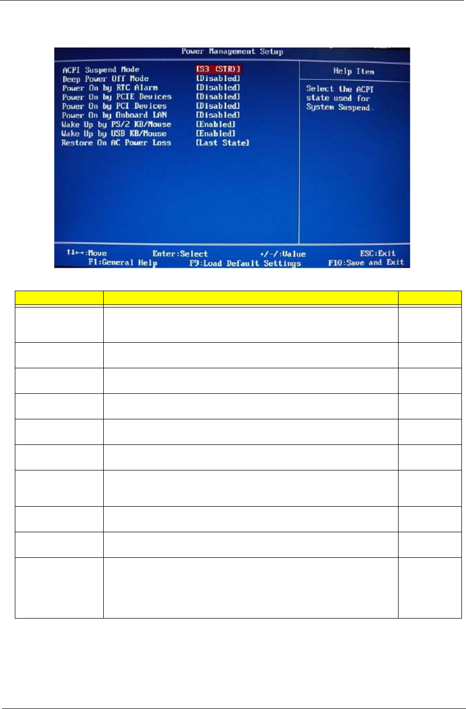
Power Management Setup
Field Description Value
ACPI Suspend
Mode
Use this item to define how your system suspends. Default value is S3
(STR), the suspend mode is suspend to RAM, i.e., the system shuts
down with the exception of a refresh current to the system memory.
S3 (STR)
S1 (POS)
Deep Power Off
Mode
Enables or disables compliance to the Energy-using Products Lot 6
Directives (EuP Lot 6). Enabled
Disabled
Power On by RTC
Alarm
Enables or disables the system to wake up from a power-saving mode
when an RTC alarm occurs.
Enabled
Disabled
Power On by PCIE
Devices
Enables or disables the system to wake up from a power-saving mode
when an event occurs on an installed PCI Express device.
Enabled
Disabled
Power On by PCI
Devices
Enables or disables the system to wake up from a power-saving mode
when an event occurs on an installed PCI device.
Enabled
Disabled
Power On by
Modem Ring
Enables or disables the system to wake up from a power-saving mode
when a modem signal is received. network message
Enabled
Disabled
Power On by
Onboard LAN
Enables or disables the system to wake up from a power-saving mode
when the onboard LAN controller received a network message.
Enabled
Disabled
Wake Up by PS/2
KB/Mouse
Enables or disables the system to wake up from a power-saving mode
when a PS/2 keyboard or mouse is used. Enabled
Disabled
Wake Up by USB
KB/Mouse Enables or disables the system to wake up from a power-saving mode
when a USB keyboard or mouse is used. Enabled
Disabled
Restore On AC
Power Loss
Select the power state when an AC power loss occurs.
• Off - The computer remains off until the power button is pressed.
• Last State - The computer reverts to the last power state before the
power loss occurred.
• On - The computer switches back on after the AC power loss.
Power Off
Power On
Last State
20 Packard Bell oneTwo M3350 / oneTwo M3351 / oneTwo L5350 / oneTwo L5351 Service Guide
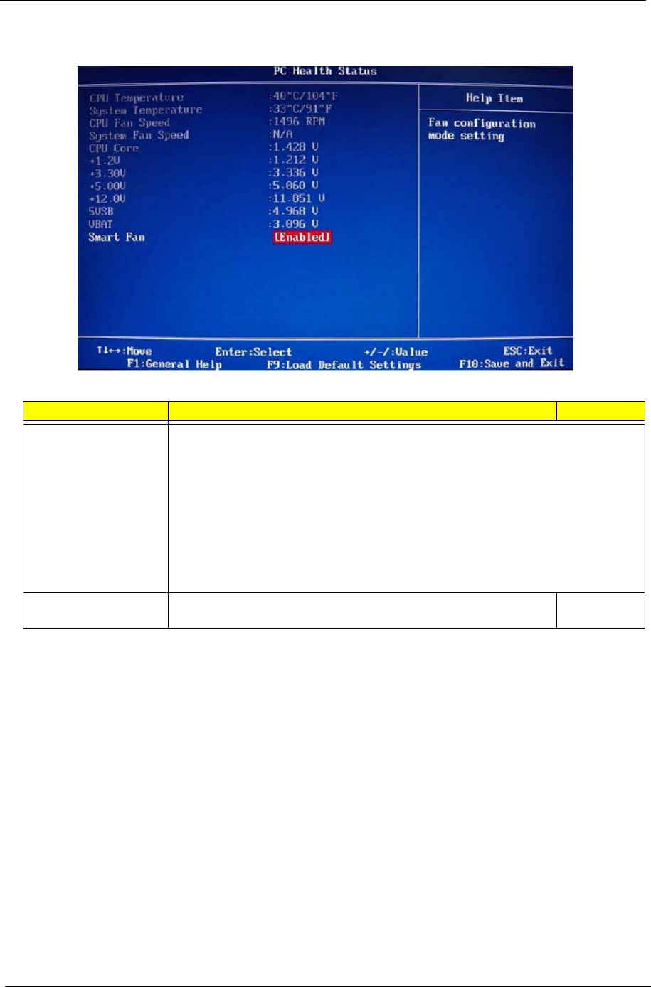
PC Health Status
Field Description Value
CPU Temperature
System Temperature
CPU Fan Speed
System Fan Speed
CPU Core
+1.1V
+3.30V
+5.00V
+12.0V
5VSB
VBAT
These items lets you monitor the parameters for critical voltages, temperatures and
fan speeds.
Smart Fan When enabled, fan speed will speed up or slow down depending on
the system temperature. Enabled
Disabled
Packard Bell oneTwo M3350 / oneTwo M3351 / oneTwo L5350 / oneTwo L5351 Service Guide 21
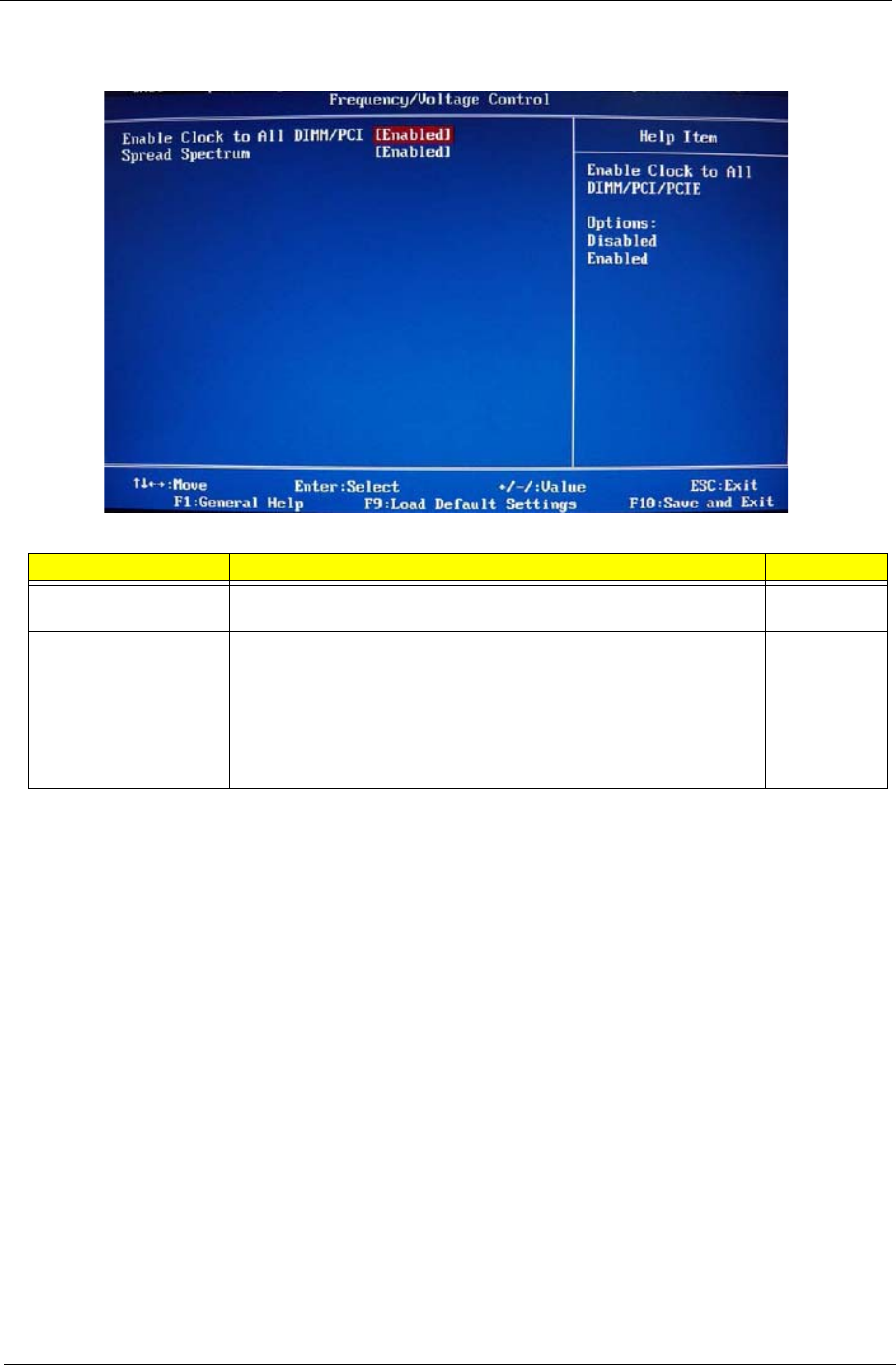
Frequency/Voltage Control
Field Description Value
Enable Clock to All
DIMM/PCI
When enabled, clock signals will be sent to the PCI and memory
slots regardless of whether the slot is occupied or not. Enabled
Disabled
Spread Spectrum When the mainboard's clock generator pulses, the extreme values of
the pulses creates EMI (electromagnetic interference). Set this field
to Enabled to reduce this EMI level. This reduces interference
problems with other electronics in the area.
Note: Remember to disable the Spread Spectrum feature if you are
overclocking. A slight jitter can introduce a temporary boost in clock
speed causing the overclocked processor to lock up.
Enabled
Disabled
22 Packard Bell oneTwo M3350 / oneTwo M3351 / oneTwo L5350 / oneTwo L5351 Service Guide
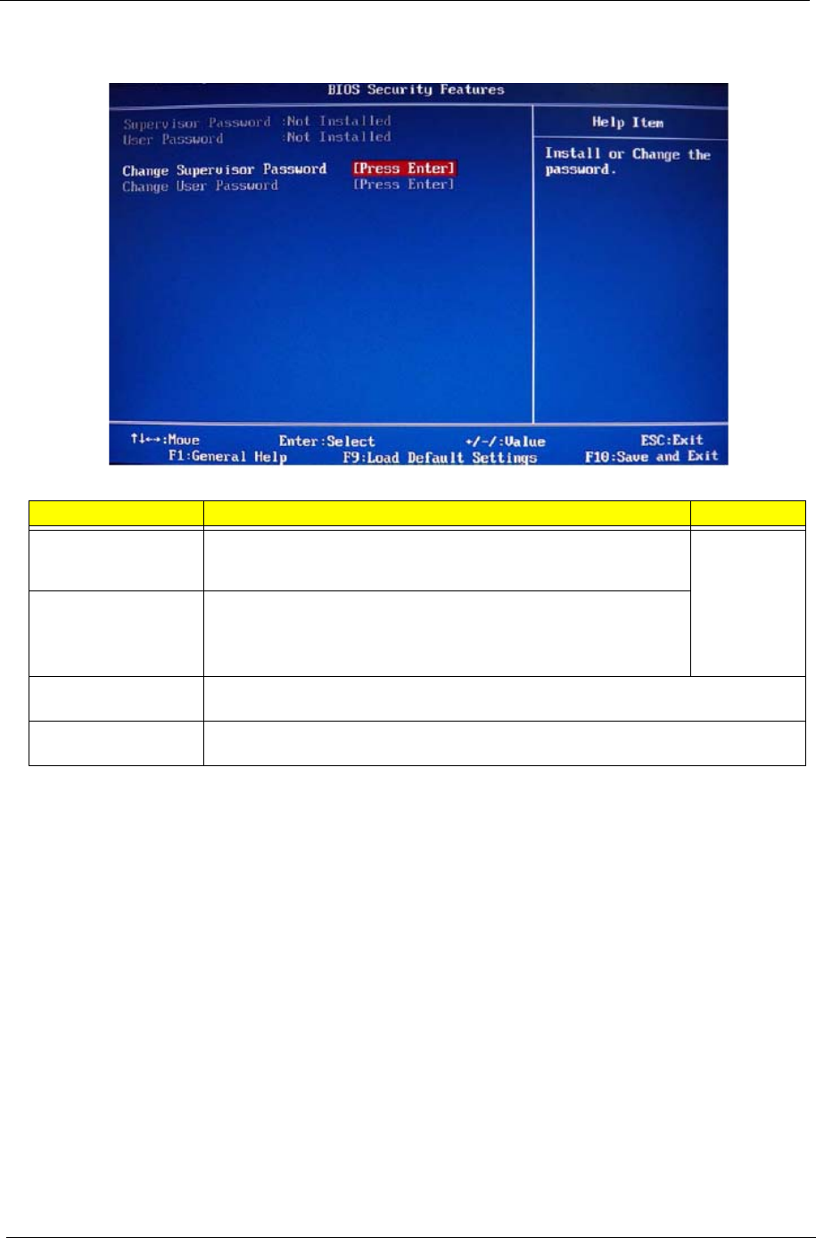
BIOS Security Features
Note the following before you define a system password:
• The maximum length of password contains 8 alphanumeric characters. The following keys are valid:
– A-Z, a-z (case-insensitive)
– 0-9
– ` - + [ ] \ ; ' , . /,
– Special keypad characters: 0-9 / * - +
• When you are prompted to enter a password, you have three tries before the system halts. Do not forget
your password. If you forget your password, you may have to return your computer to your dealer to reset
it.
Field Description Value
Supervisor Password Displays the supervisor password status. When set to Installed, this
password will allow the user to access and change all settings in the
Setup Utility.
Installed
Not Installed
User Password Displays the user password status. Only the following menus will be
accessible when this password is set as Installed:
• System Date and System Time
• Exit Without Saving
Change Supervisor
Password
Press Enter to change the supervisor password.
Change User
Password
Press Enter to change the user password.

Packard Bell oneTwo M3350 / oneTwo M3351 / oneTwo L5350 / oneTwo L5351 Service Guide 23
To set a system password:
1. Select Change Supervisor Password or Change User Password, then press Enter.
The password box appears.
2. Type a password then press Enter.
3. Retype the password to verify the first entry, then press Enter.
You will be prompted to save the new password.
4. Press Enter.
5. Press F10 to save the password and close the Setup Utility.
To change a system password:
1. Select Change Supervisor Password or Change User Password, then press Enter.
The password box appears.
2. Type the original password, then press Enter.
3. Type a new password, then press Enter.
4. Retype the new password to verify the first entry, then press Enter.
You will be prompted to save the new password.
5. Press Enter.
6. Press F10 to save the password and close the Setup Utility.
To remove a system password:
1. Select Change Supervisor Password or Change User Password, then press Enter.
The password box appears.
2. Type the original password, then press Enter.
3. Press Enter twice without entering anything in the new and confirm password fields.
You will be prompted to confirm the password removal.
4. Press Enter.
5. Press F10 to save the changes you made and close the Setup Utility.
NOTE You need to set a supervisor password first before setting the user password.
IMPORTANT Be very careful when typing your password because the characters do not appear on the
screen. Only shaded blocks representing each typed character are visible.
NOTE When the supervisor password is removed, the user password will also be remove.
24 Packard Bell oneTwo M3350 / oneTwo M3351 / oneTwo L5350 / oneTwo L5351 Service Guide
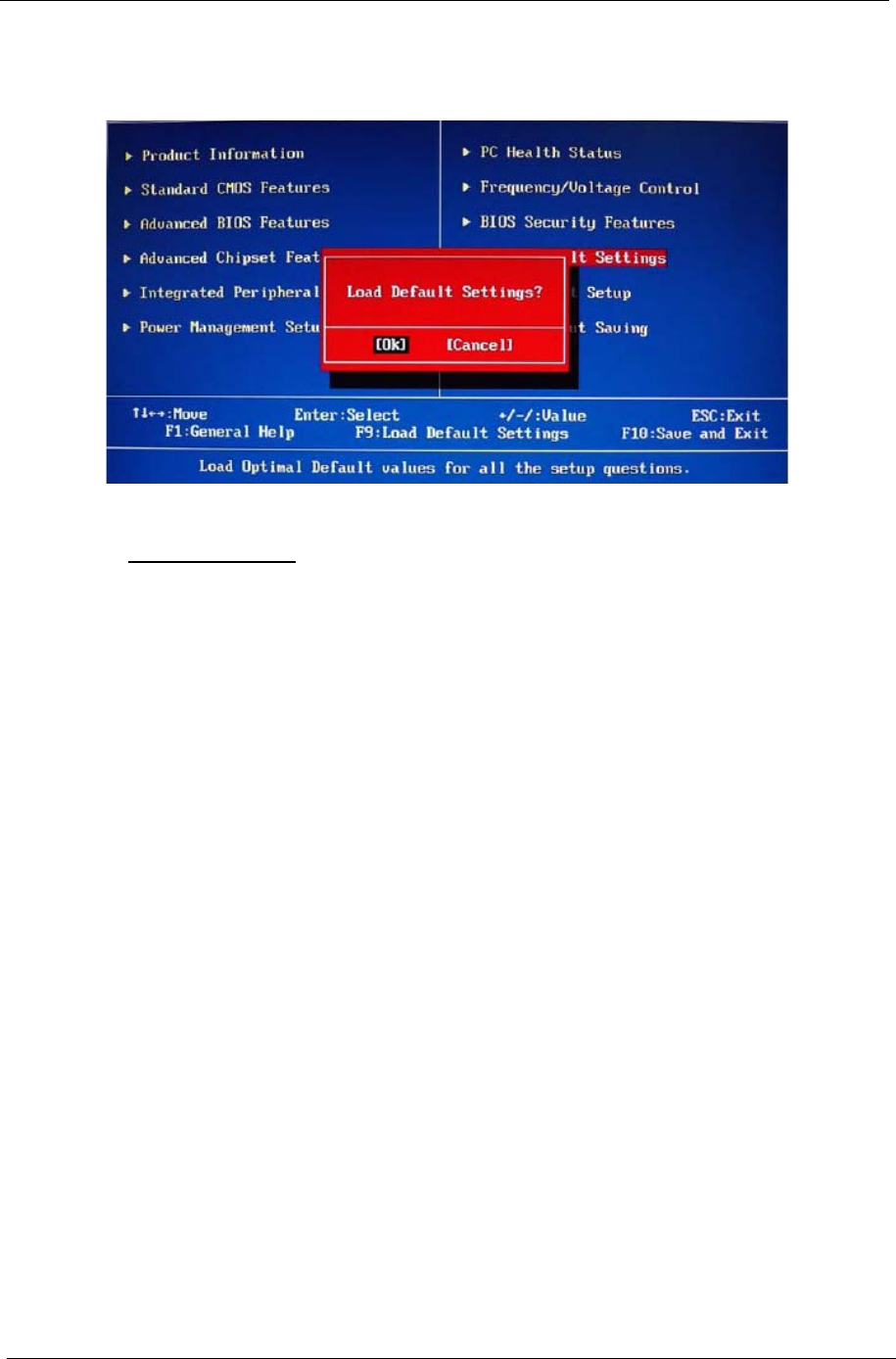
Load Default Settings
Execute this menu to load the factory-default settings for all Setup parameters. Keyboard shortcut: F9
Perform the steps below to load the system default settings:
1. Select Load Default Settings, then press Enter.
You will be prompted to load the system defaults.
2. Select OK, then press Enter.
3. Press F10 to save the changes you made and close the Setup Utility.
Save & Exit Setup
Execute this menu to save the changes made and closes the Setup Utility. Keyboard shortcut: F10
Exit Without Saving
Execute this menu to closes the Setup Utility without making any changes.

Packard Bell oneTwo M3350 / oneTwo M3351 / oneTwo L5350 / oneTwo L5351 Service Guide 25
This chapter provides step-by-step instructions on how to disassemble the computer for maintenance and
troubleshooting purposes.
Disassembly Tools
In performing the disassembly process, you will need the following tools:
• Wrist-grounding strap and conductive mat for preventing electrostatic discharge
• Philips screwdriver
• Hex screwdriver
• Flat screwdriver
Pre-disassembly Procedure
Before proceeding with the disassembly procedure, perform the steps listed below:
1. Make sure that the optical disc drive and the card reader slot are empty.
2. Turn off the power to the computer and all peripherals.
3. Unplug the power cord from the computer.
4. Unplug the network cable and all connected peripheral devices from the computer.
5. Place the computer on a flat, steady surface with the rear cover facing upward.
NOTES • To reinstall the system components and assemble the unit, perform the disassembly procedures in
reverse.
• The screws for the different components vary in size. During the disassembly process, group the
screws with their corresponding components to avoid mismatches when putting back the
components.
System Disassembly
Chapter 3
26 Packard Bell oneTwo M3350 / oneTwo M3351 / oneTwo L5350 / oneTwo L5351 Service Guide
Disassembly Procedures
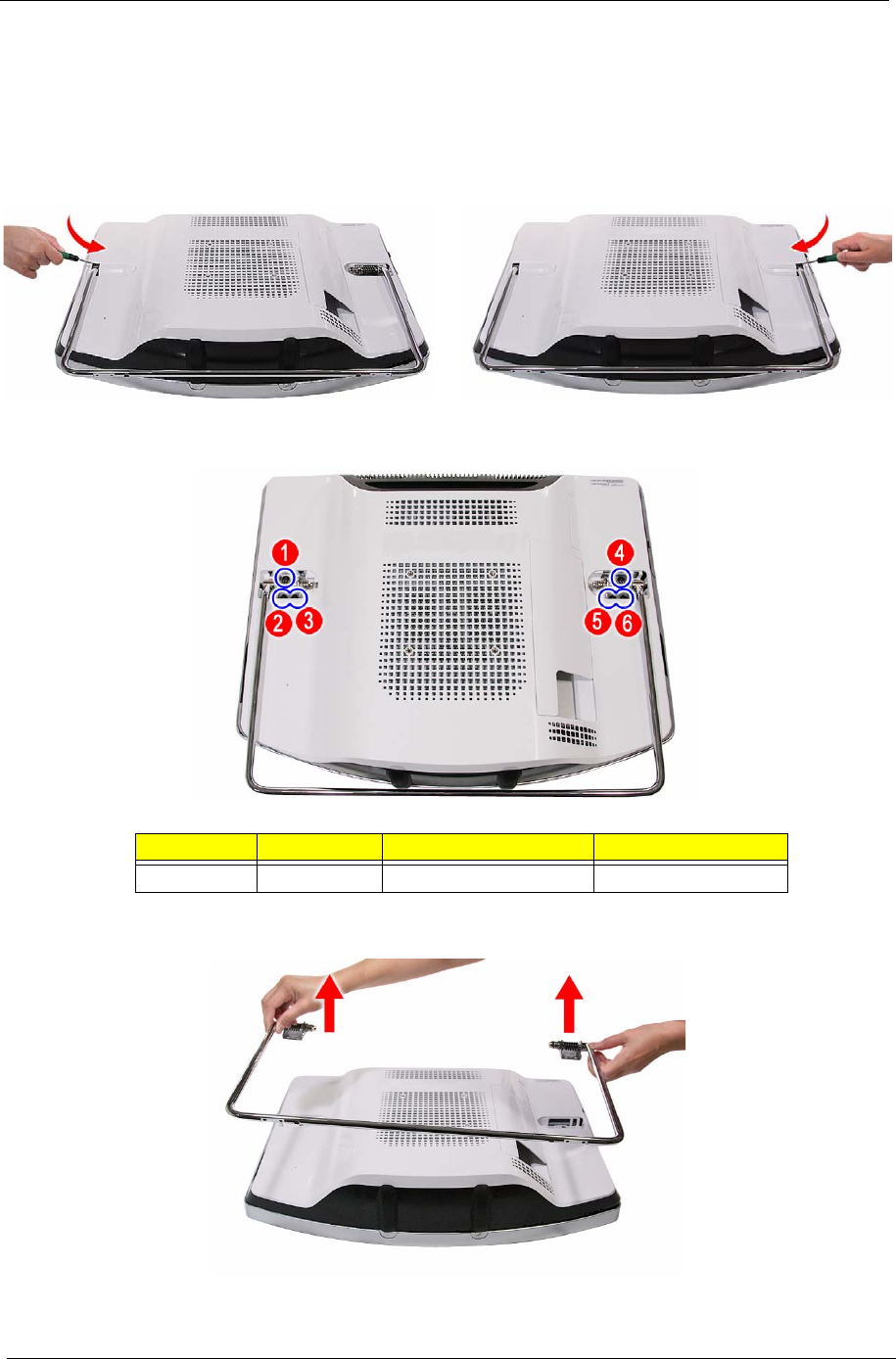
Removing the Computer Stand
1. Perform the “Pre-disassembly Procedure” on page 25.
2. Use a flat screwdriver to pry off the plastic shell covering the computer stand screws.
3. Remove the screws securing the computer stand.
4. Remove the computer stand.
Quantity Color Torque Part Number
6Black 4.0–4.5 kgf-cm 86.00N85.266
Packard Bell oneTwo M3350 / oneTwo M3351 / oneTwo L5350 / oneTwo L5351 Service Guide 27
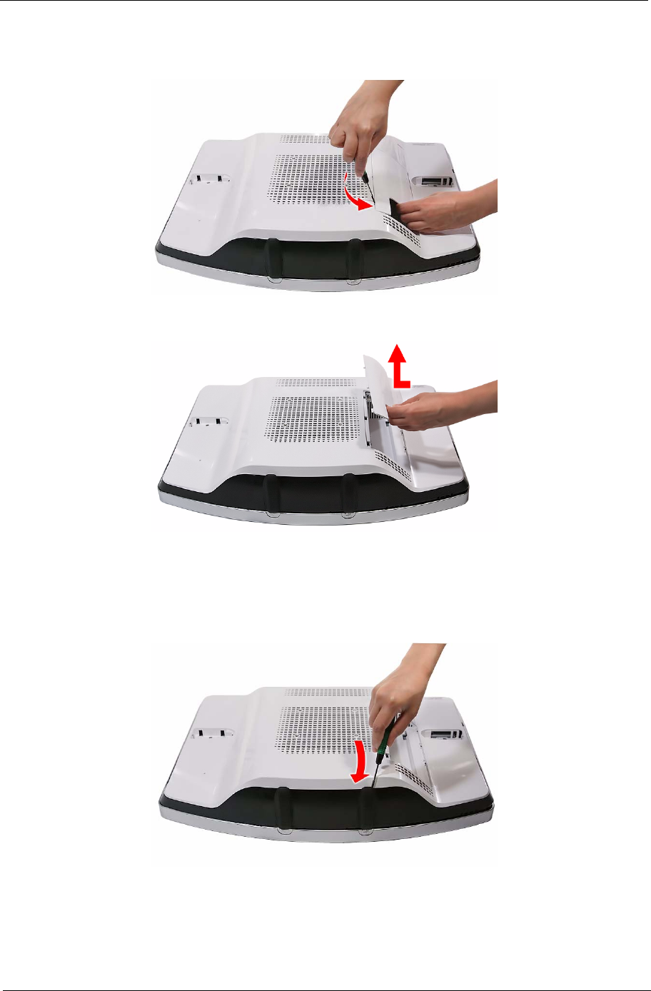
Removing the I/O Cable Cover
1. Use a flat screwdriver to pry off the I/O cable cover.
2. Remove the I/O cable cover
Removing the Rubber Feet
1. Perform the “Pre-disassembly Procedure” on page 25.
2. Use a flat screwdriver to pry off the rubber feet from the computer base.
28 Packard Bell oneTwo M3350 / oneTwo M3351 / oneTwo L5350 / oneTwo L5351 Service Guide
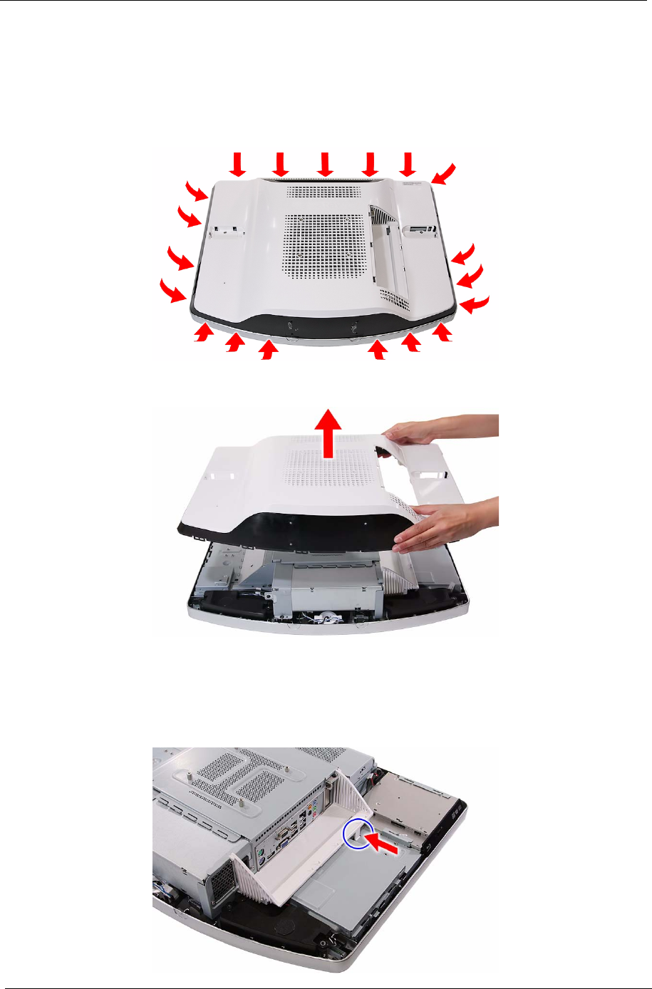
Removing the Rear Cover
1. Remove the computer stand by following the procedure described on page 26.
2. Remove the I/O cable cover and the rubber feet by following the procedures described on page 27.
3. Use a flat screwdriver to carefully pry loose the rear cover from the front bezel.
The picture below shows the location of the plastic snaps securing the rear cover to the front bezel.
4. Toggle the cover from left to right to loosen its hold on the front bezel, then detach the rear cover.
Removing the I/O Cable Plate
1. Remove the rear cover by following the procedure described in the previous section.
2. Push the latch to disengage the I/O cable plate from the main chassis.
Packard Bell oneTwo M3350 / oneTwo M3351 / oneTwo L5350 / oneTwo L5351 Service Guide 29
3. Remove the I/O cable plate.
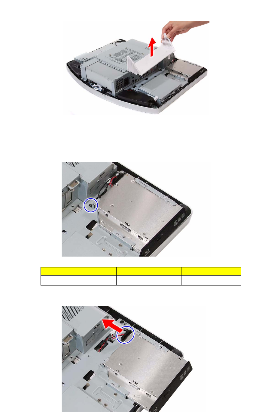
Removing the Optical Disc Drive
1. Remove the rear cover by following the procedure described on page 28.
2. Remove the screw securing the ODD.
3. Slide the ODD outward, then disconnect the ODD SATA cable from the drive.
Quantity Color Torque Part Number
1Black 4.0–4.5 kgf-cm 86.00B75.240
30 Packard Bell oneTwo M3350 / oneTwo M3351 / oneTwo L5350 / oneTwo L5351 Service Guide
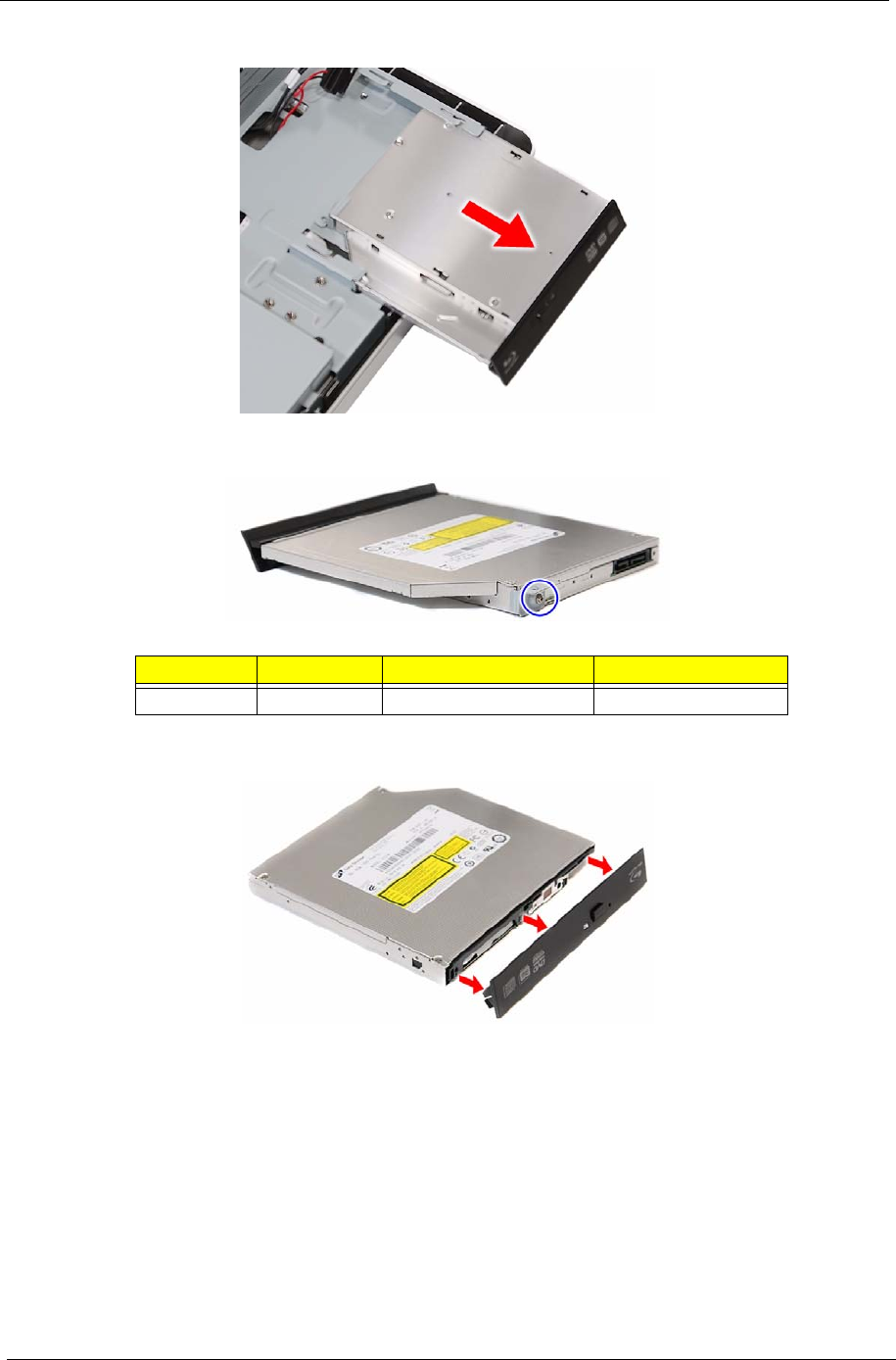
4. Remove the ODD from the main chassis.
5. Remove the screw securing the ODD bracket.
6. Detach the ODD bezel from the module.
Quantity Color Torque Part Number
1Silver 1.3–1.5 kgf-cm 86.7A122.4R0
Packard Bell oneTwo M3350 / oneTwo M3351 / oneTwo L5350 / oneTwo L5351 Service Guide 31
Removing the Scaler Board
1. Remove the rear cover by following the procedure described on page 28.
2. Remove the screw securing the scaler board cover.
3. Slide the scaler board cover towards the speaker area to disengage the cover tabs from the main chassis,
then remove the scaler board cover.
4. Disconnect all the cables from the scaler board.
Quantity Color Torque Part Number
1Black 4.0–4.5 kgf-cm 86.00B75.240
32 Packard Bell oneTwo M3350 / oneTwo M3351 / oneTwo L5350 / oneTwo L5351 Service Guide
5. Remove the screws securing the scaler board.
6. Remove the scaler board.
Quantity Color Torque Part Number
4Black 4.0 kgf-cm 86.00B75.240
A circuit board that is >10 cm2 has been highlighted with a yellow rectangle as shown in the
above image. Follow local regulations for disposing this type of circuit board.
Packard Bell oneTwo M3350 / oneTwo M3351 / oneTwo L5350 / oneTwo L5351 Service Guide 33
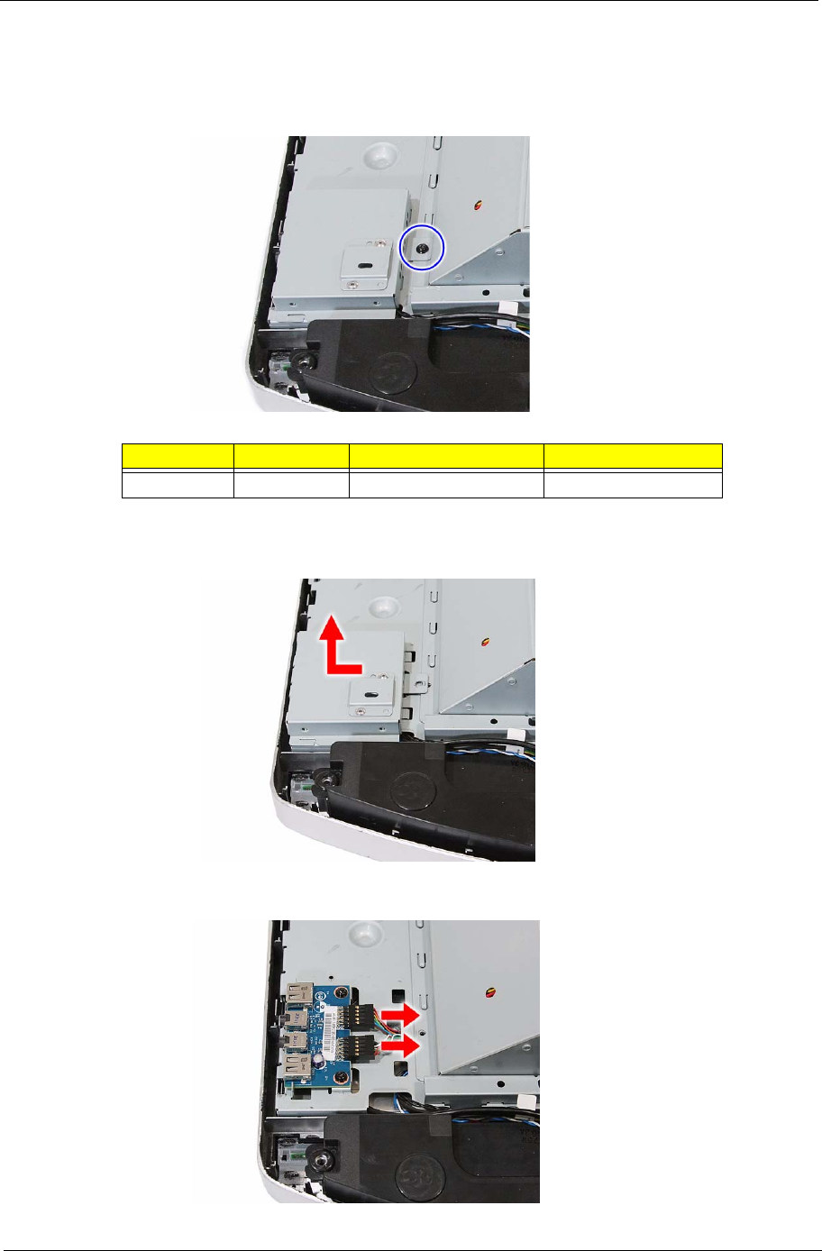
Removing the USB/Audio Board
1. Remove the rear cover by following the procedure described on page 28.
2. Remove the screw securing the USB/audio board cover.
3. Slide the USB/audio board cover outward to disengage the cover tabs from the main chassis, then
remove the USB/audio board cover.
4. Disconnect the two cables from the USB/audio board.
Quantity Color Torque Part Number
1Black 4.0–4.5 kgf-cm 86.00B75.240
34 Packard Bell oneTwo M3350 / oneTwo M3351 / oneTwo L5350 / oneTwo L5351 Service Guide
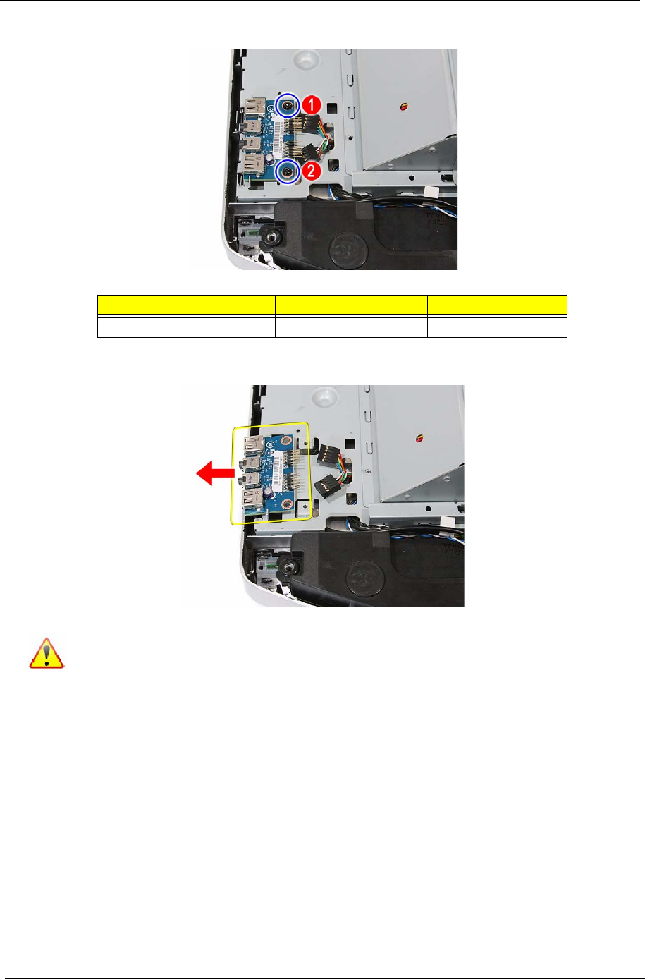
5. Remove the screws securing the USB/audio board.
6. Slide the USB/audio board out of its tabs.
Quantity Color Torque Part Number
2Black 4.0 kgf-cm 86.00B75.240
A circuit board that is >10 cm2 has been highlighted with a yellow rectangle as shown in the
above image. Follow local regulations for disposing this type of circuit board.
Packard Bell oneTwo M3350 / oneTwo M3351 / oneTwo L5350 / oneTwo L5351 Service Guide 35
Removing the Wall Mount Plate
1. Remove the rear cover by following the procedure described on page 28.
2. Remove the screws securing the wall mount plate.
3. Slide the wall mount plate towards the HDD area to disengage the plate tabs from the main chassis, then
remove the wall mount plate.
Quantity Color Torque Part Number
2Black 4.0–4.5 kgf-cm 86.00B75.240
36 Packard Bell oneTwo M3350 / oneTwo M3351 / oneTwo L5350 / oneTwo L5351 Service Guide
Removing the TV Tuner Card
1. Remove the wall mount plate by following the procedure described in the previous section.
2. Disconnect the TV tuner card cable.
3. Remove the screw securing the TV tuner card bracket.
4. Disconnect TV tuner card from its expansion slot.
Quantity Color Torque Part Number
1Black 4.0–4.5 kgf-cm 86.00B75.240
Packard Bell oneTwo M3350 / oneTwo M3351 / oneTwo L5350 / oneTwo L5351 Service Guide 37
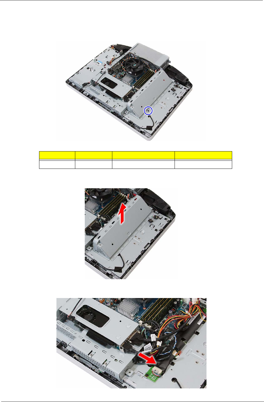
Removing the Graphics Card
1. Remove the wall mount plate by following the procedure described on page 35.
2. Remove the screw securing the inverter board cover.
3. Remove the inverter board cover.
4. Disconnect the HDMI cable from the graphics card.
Quantity Color Torque Part Number
1Black 4.0–4.5 kgf-cm 86.00B75.240
38 Packard Bell oneTwo M3350 / oneTwo M3351 / oneTwo L5350 / oneTwo L5351 Service Guide
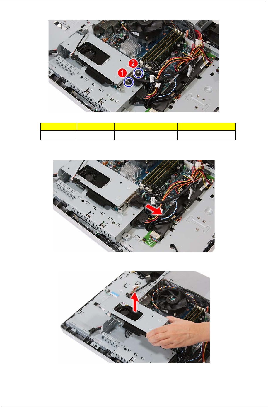
5. Remove the hex screws securing the serial-to-DVI cable.
6. Disconnect the serial-to-DVI cable from the graphics card.
7. Disconnect the graphics card assembly from its expansion slot.
Quantity Color Torque Part Number
2Silver 4.5 kgf-cm 86.80536.7R2
Packard Bell oneTwo M3350 / oneTwo M3351 / oneTwo L5350 / oneTwo L5351 Service Guide 39
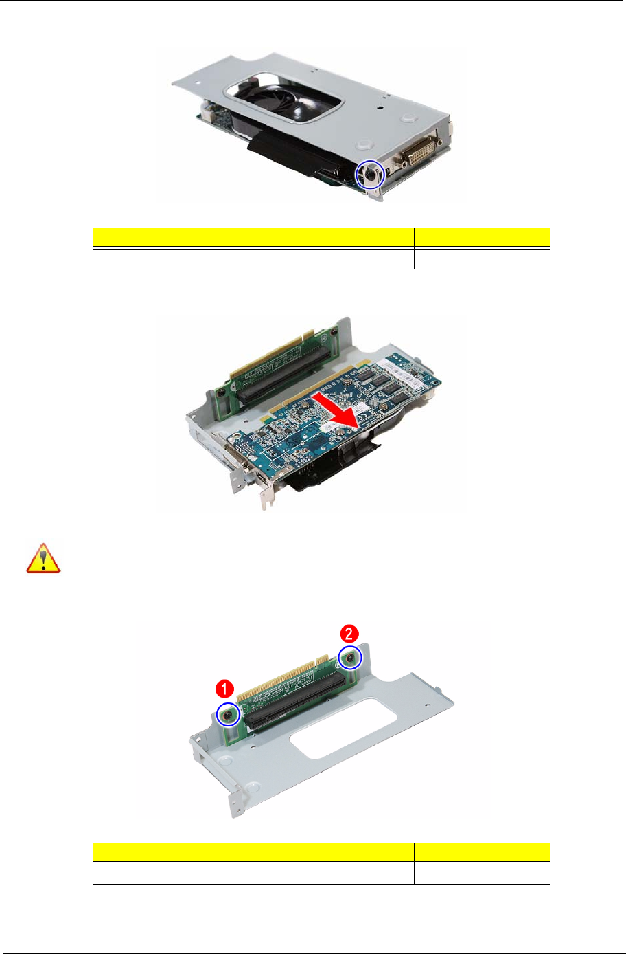
8. Remove the screw securing the graphics card bracket.
9. Disconnect the graphics card from its riser board.
10. Remove the screws securing the graphics card riser board.
Quantity Color Torque Part Number
1Black 4.0–4.5 kgf-cm 86.00B75.240
A circuit board that is >10 cm2 has been highlighted with a yellow rectangle as shown in the
above image. Follow local regulations for disposing this type of circuit board.
Quantity Color Torque Part Number
2Black 4.0–4.5 kgf-cm 86.00B75.240
40 Packard Bell oneTwo M3350 / oneTwo M3351 / oneTwo L5350 / oneTwo L5351 Service Guide
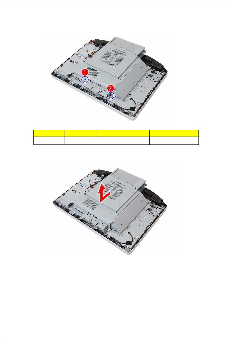
11. Remove the graphics card riser board from its bracket.
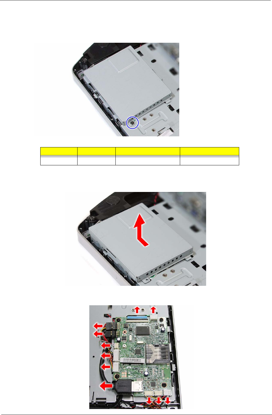
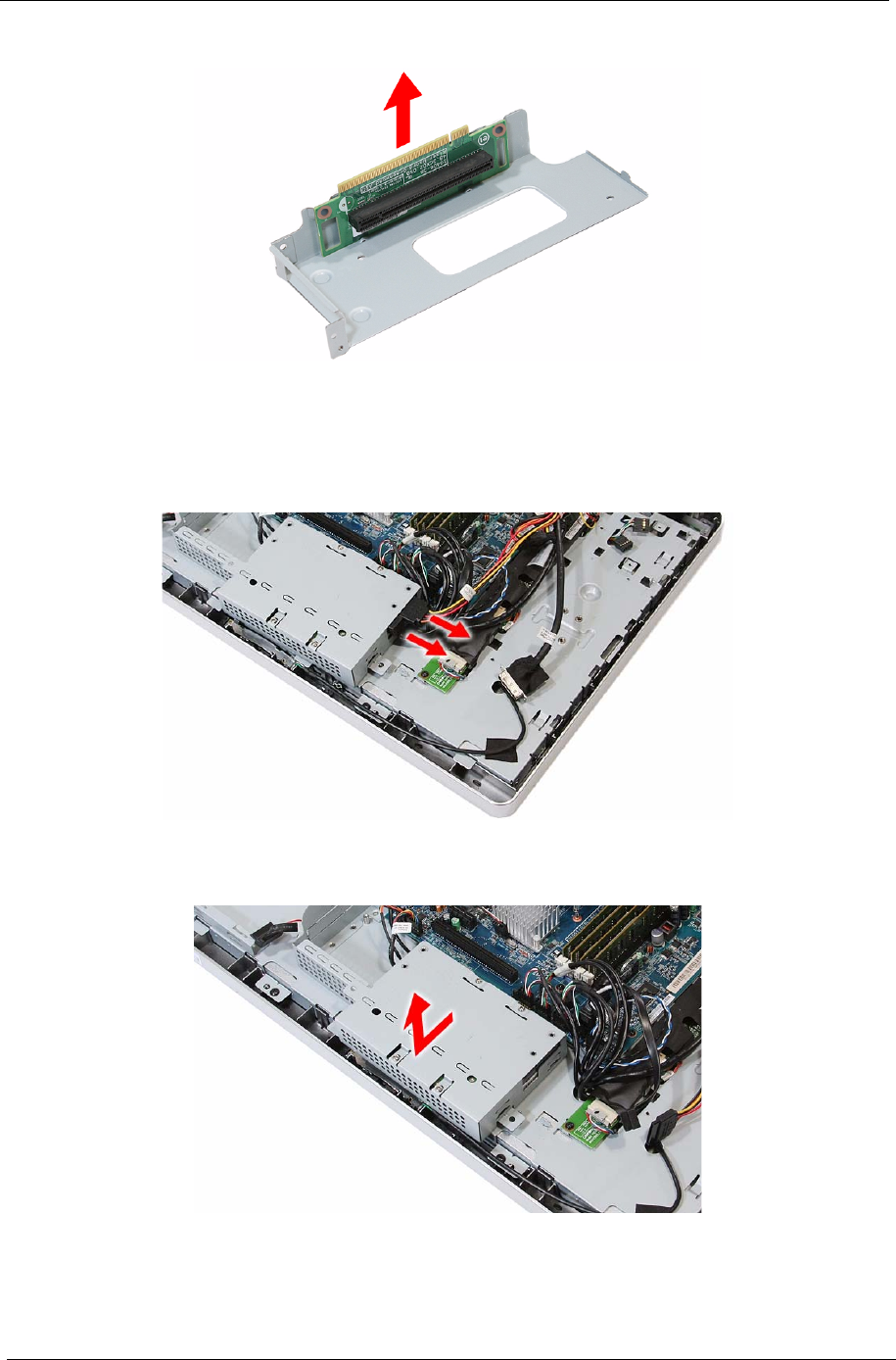
Removing the Hard Disk Drive
1. Remove the graphics card by following the procedure described on page 37.
2. Disconnect the power and SATA cables from the hard drive.
3. Slide the HDD assembly outward to disengage the assembly from the main chassis, then remove the
HDD assembly.
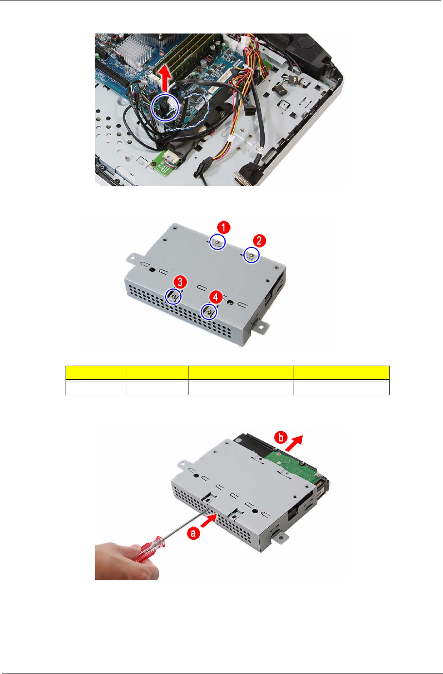
Packard Bell oneTwo M3350 / oneTwo M3351 / oneTwo L5350 / oneTwo L5351 Service Guide 41
4. Disconnect the HDD SATA cable from the mainboard.
5. Remove the screws securing the hard drive to its cage.
6. Use a small metal screwdriver to push the hard drive out of its cage (a), then pull out the drive out (b).
Quantity Color Torque Part Number
4Silver 4.0–4.5 kgf-cm 86.00J44.C60
42 Packard Bell oneTwo M3350 / oneTwo M3351 / oneTwo L5350 / oneTwo L5351 Service Guide
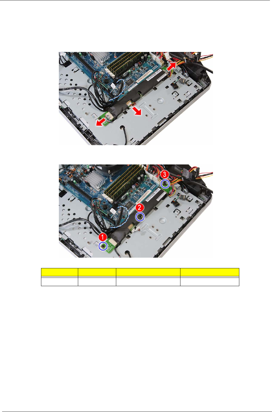
Removing the Inverter Board
1. Remove the wall mount plate by following the procedure described on page 35.
2. Remove the inverter board cover by following steps 2 and 3 on page 37.
3. Disconnect all cables from the inverter board.
4. Remove the screws securing the inverter board.
Quantity Color Torque Part Number
3Black 4.0 kgf-cm 86.00B75.240
Packard Bell oneTwo M3350 / oneTwo M3351 / oneTwo L5350 / oneTwo L5351 Service Guide 43
5. Remove the inverter board.
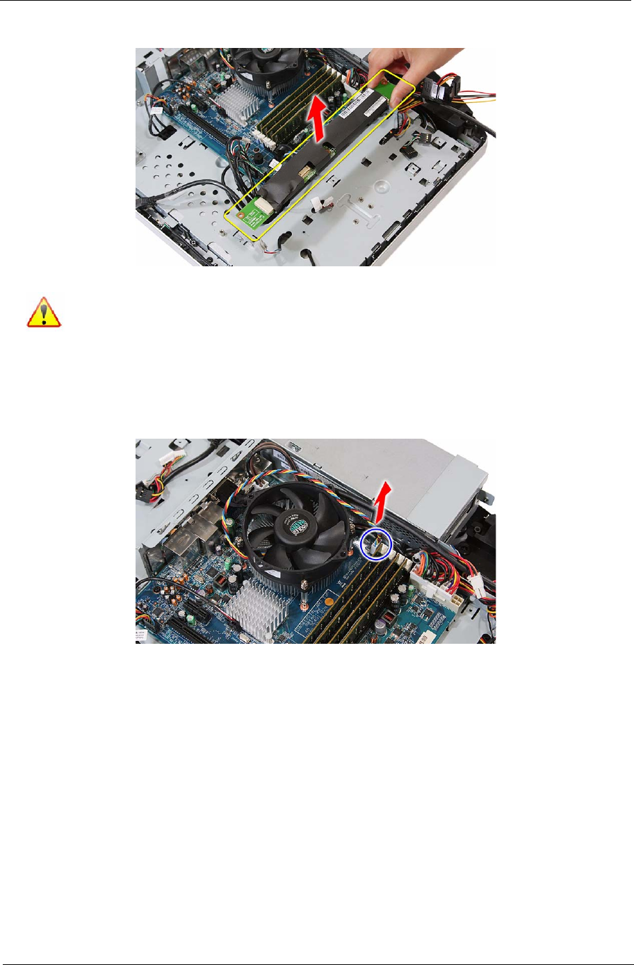
Removing the Heat Sink Fan (HSF) Assembly
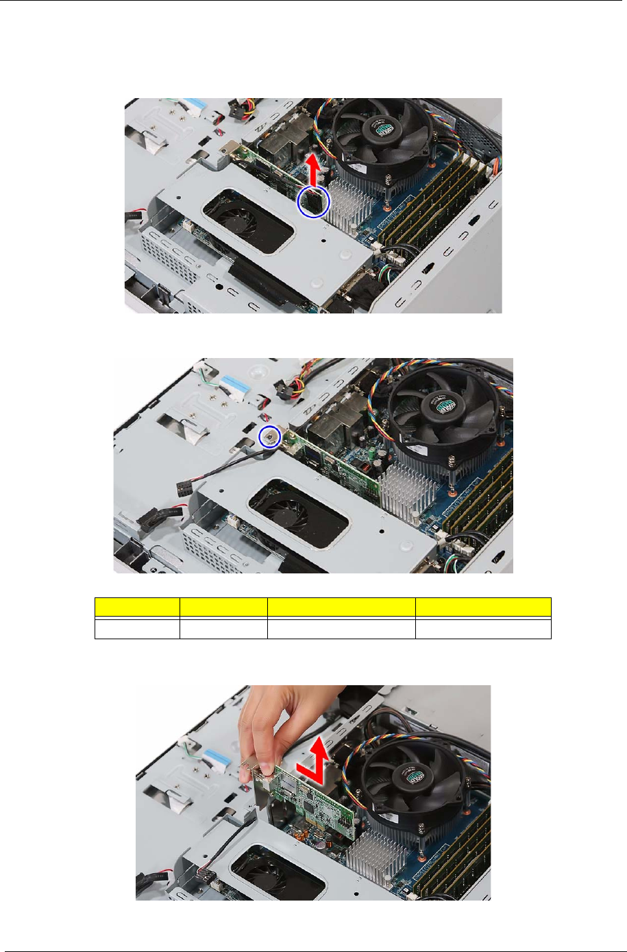
1. Remove the wall mount plate by following the procedure described on page 35.
2. Disconnect the HSF cable from its mainboard connector.
A circuit board that is >10 cm2 has been highlighted with a yellow rectangle as shown in the
above image. Follow local regulations for disposing this type of circuit board.
44 Packard Bell oneTwo M3350 / oneTwo M3351 / oneTwo L5350 / oneTwo L5351 Service Guide
3. Loosen the HSF's spring-loaded screws in a diagonally opposite pattern (an "X" pattern).
4. Remove the HSF assembly.
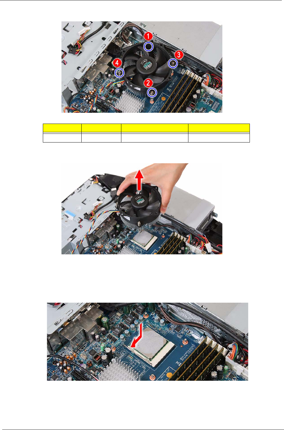
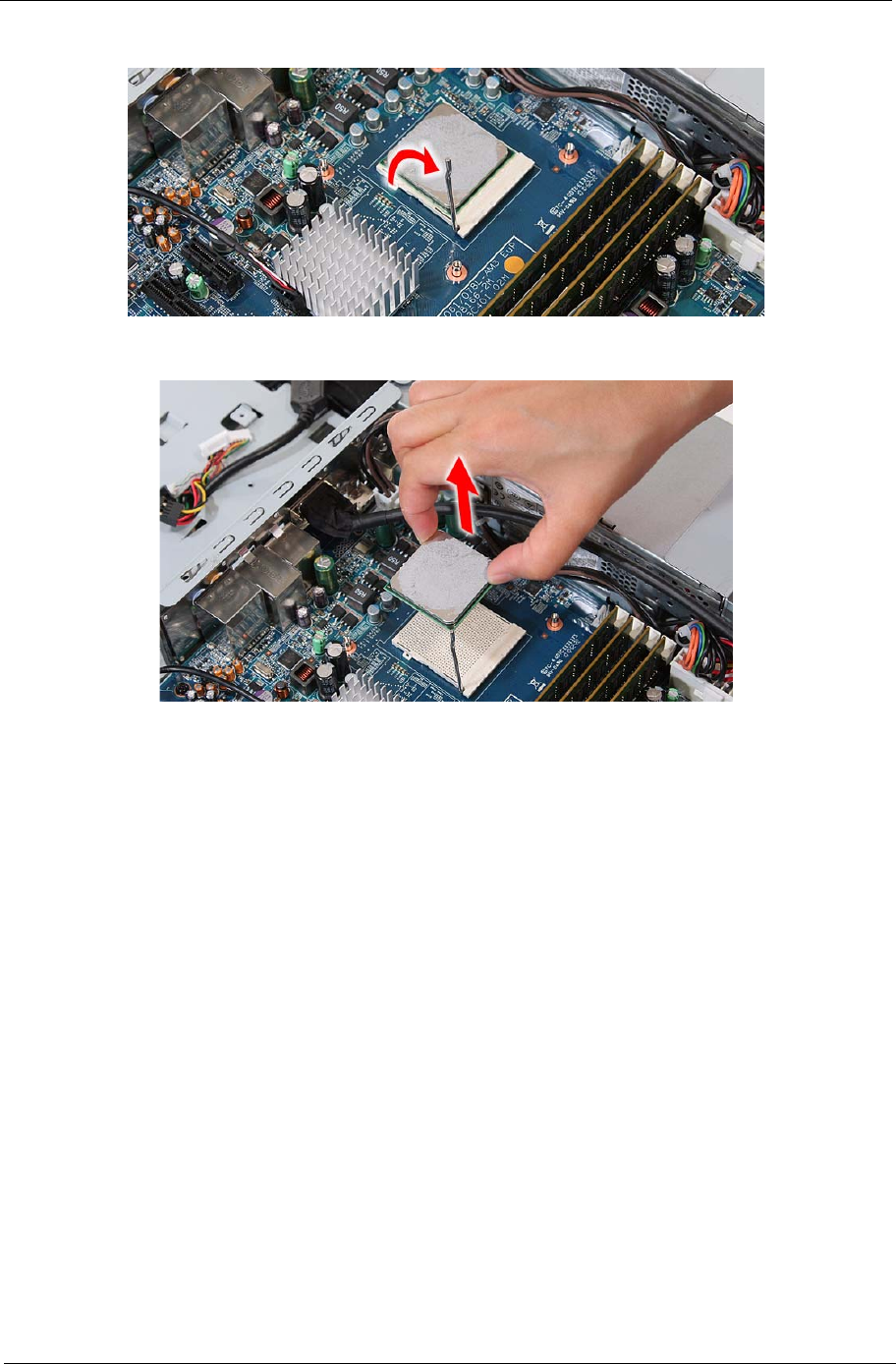
Removing the Processor
1. Remove the HSF assembly by following the procedure described on the previous section.
2. Press down the socket lever, then move it left to release.
Quantity Color Torque Part Number
4Silver 4.0–4.5 kgf-cm –
Packard Bell oneTwo M3350 / oneTwo M3351 / oneTwo L5350 / oneTwo L5351 Service Guide 45
3. Rotate the socket lever to the open position.
4. Gently lift the processor out of its socket.
CAUTION DO NOT lay the processor on its base to avoid bending or damaging the pins underneath it.
IMPORTANT When installing a processor:
• Note the golden arrow on the corner to make sure the processor is properly oriented over
the socket.
• Moisten a soft cloth with isopropyl alcohol and clean the processor die to remove any
thermal grease residue. Wipe the die surface several times to make sure that no particles
or dust contaminants are evident. Allow the alcohol to evaporate before continuing. Apply
just enough thermal grease to evenly coat the surface of the processor die.
46 Packard Bell oneTwo M3350 / oneTwo M3351 / oneTwo L5350 / oneTwo L5351 Service Guide
Removing the Memory Modules
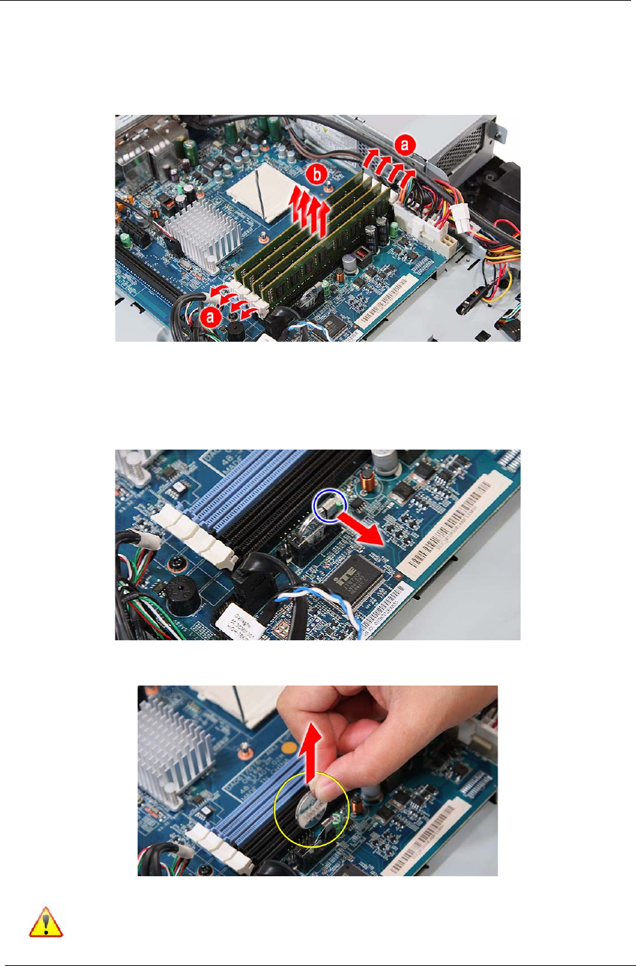
1. Remove the wall mount plate by following the procedure described on page 35.
2. Open the holding clips securing the memory modules (a), then remove the memory modules from the
DIMM slots (b).
Removing the RTC Battery
1. Remove the wall mount plate by following the procedure described on page 35.
2. Detach the socket latch from the RTC battery.
3. Remove the RTC battery from its socket.
The RTC battery has been highlighted with a yellow circle in the above image. Detach the RTC
battery and follow local regulations for disposing it.
Packard Bell oneTwo M3350 / oneTwo M3351 / oneTwo L5350 / oneTwo L5351 Service Guide 47
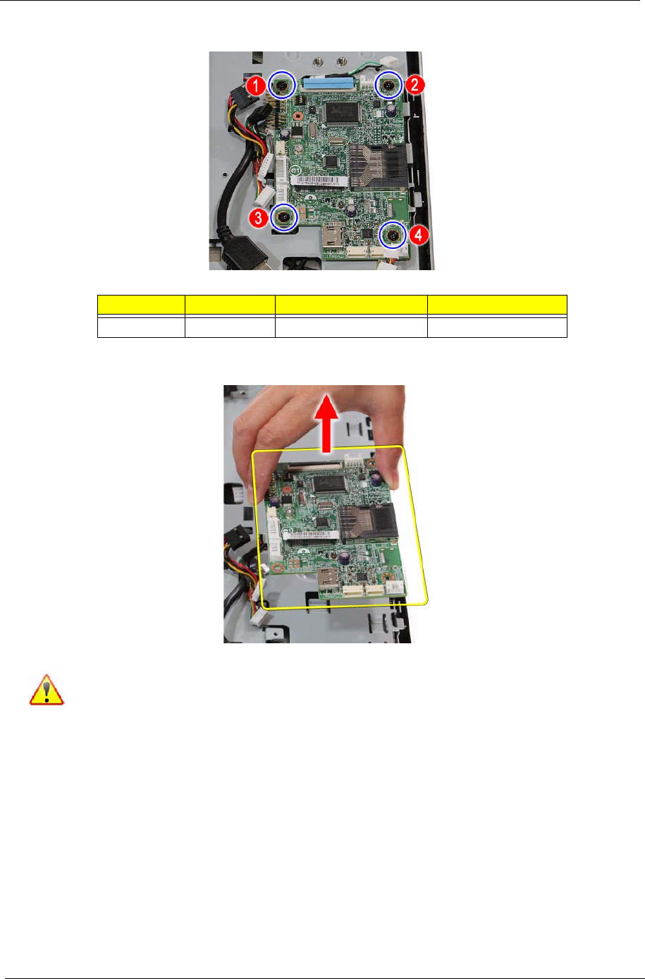
Removing the Mainboard
1. Remove the TV tuner card by following the procedure described on page 36.
2. Remove the graphics card by following the procedure described on page 37
3. Remove the hard drive by following the procedure described on page 40.
4. Remove the HSF assembly by following the procedure described on page 43.
5. Remove the processor by following the procedure described on page 44.
6. Remove the memory modules by following the procedure described on page 46.
7. Remove the RTC battery by following the procedure described on the previous section.
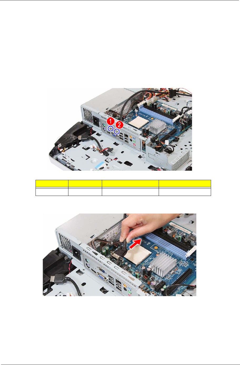
8. Remove the hex screws securing the serial-to-DVI cable.
9. Detach the serial-to-DVI cable from the I/O port panel bracket.
Quantity Color Torque Part Number
2Silver 4.5 kgf-cm 86.80536.7R2
48 Packard Bell oneTwo M3350 / oneTwo M3351 / oneTwo L5350 / oneTwo L5351 Service Guide
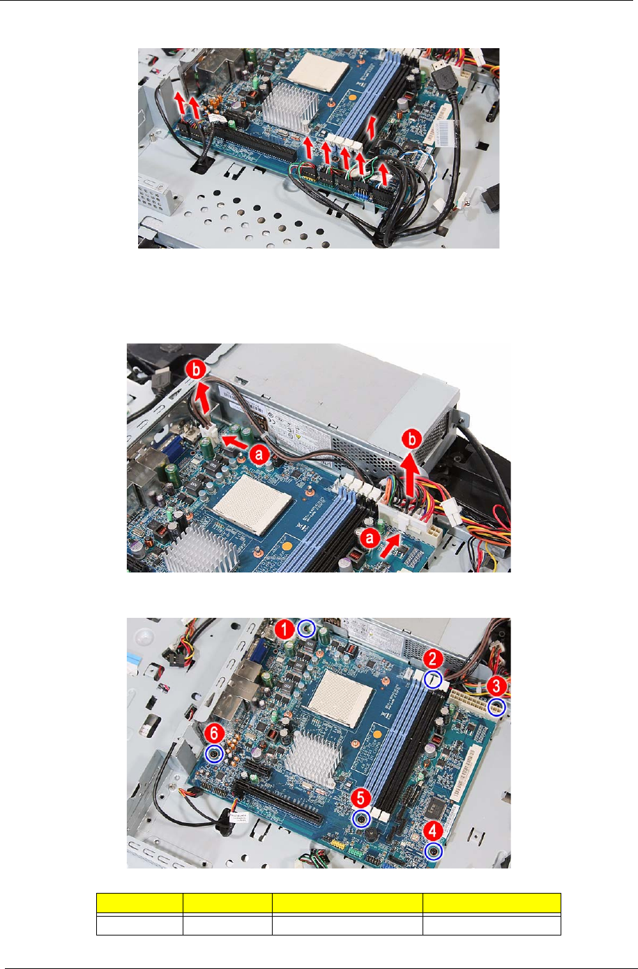
10. Disconnect all cables from the upper edge area of the mainboard.
11. Disconnect the 4-pin and 20-pin ATX power cables from their mainboard connectors.
a. Press the top portion of the cable’s retaining latch
b. Pull the cable straight up from its connector.
12. Remove the screws securing the mainboard.
Quantity Color Torque Part Number
6Black 4.0 kgf-cm 86.00B75.240
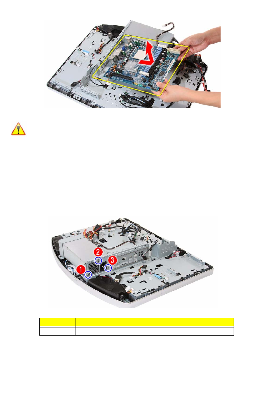
Packard Bell oneTwo M3350 / oneTwo M3351 / oneTwo L5350 / oneTwo L5351 Service Guide 49
13. Remove the mainboard.
Removing the Power Supply Unit
1. Disconnect the scalar board power cable by performing steps 1–4 of the scalar board removal procedure
on page 31.
2. Disconnect the hard drive power cable by performing steps 1 and 2 of the HDD removal procedure on
page 40.
3. Disconnect the ATX power cables by performing step 11 of the mainboard removal procedure on page 48.
4. Remove the screws securing the PSU to the main chassis.
A circuit board that is >10 cm2 has been highlighted with a yellow rectangle as shown in the
above image. Follow local regulations for disposing this type of circuit board.
Quantity Color Torque Part Number
3Silver 4.0 kgf-cm 86.00J44.C60
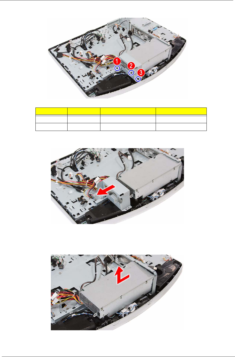
50 Packard Bell oneTwo M3350 / oneTwo M3351 / oneTwo L5350 / oneTwo L5351 Service Guide
5. Remove the screws securing the PSU bracket.
6. Detach the PSU bracket from the power supply unit.
7. Remove power supply unit from the front bezel and lay it down beside the system.
Some PSU connector cables are still secured underneath the main chassis so you won’t be able to
remove the PSU completely
Quantity Color Torque Part Number
2 (#1-2) Black 4.0 kgf-cm 86.00J44.C60
1 (#3) Black 4.0 kgf-cm 86.3AR26.8R0
Packard Bell oneTwo M3350 / oneTwo M3351 / oneTwo L5350 / oneTwo L5351 Service Guide 51
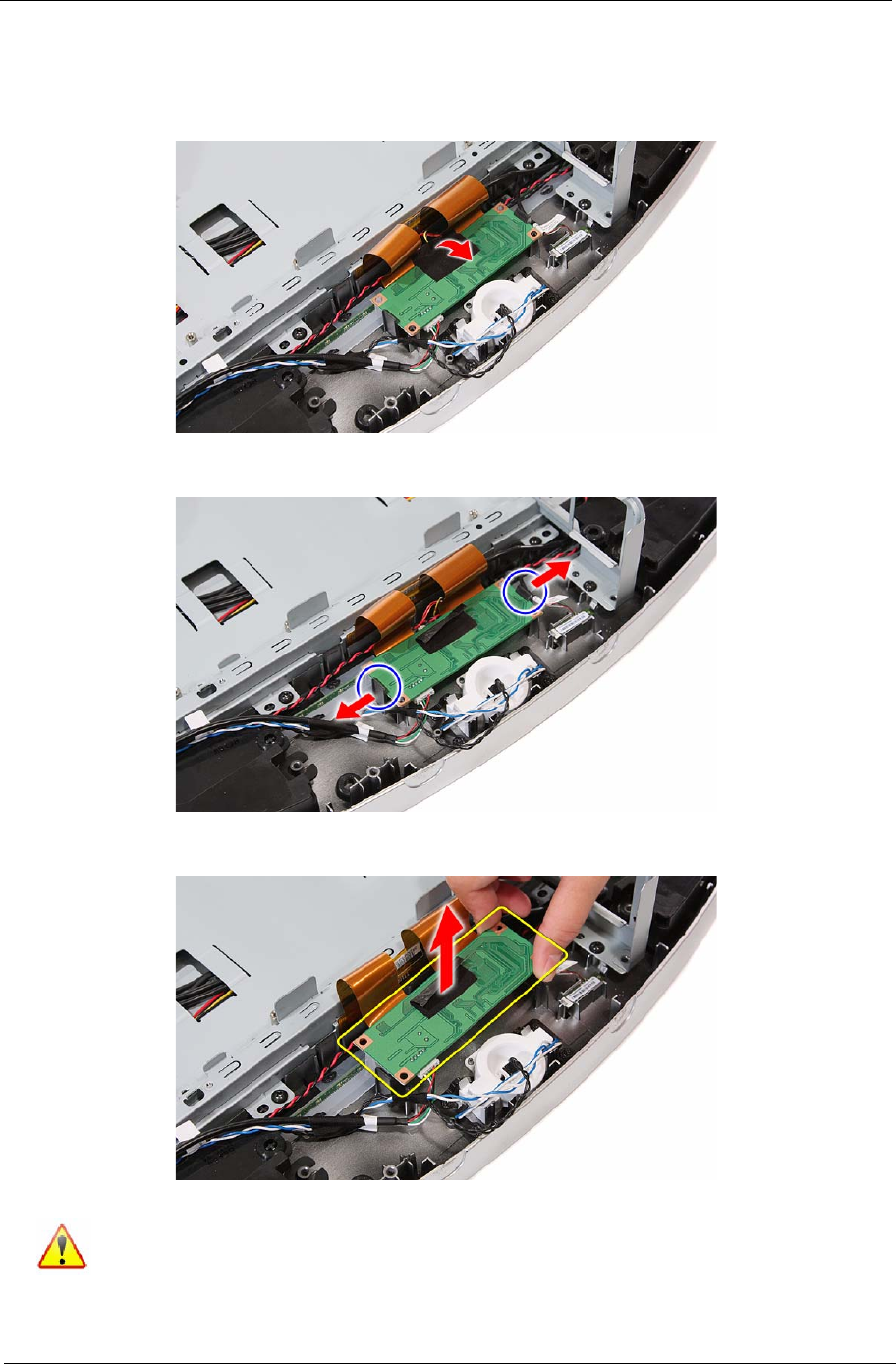
Removing the Touchscreen Control Board
1. Remove the PSU by following the procedure described on page 49.
2. Detach the black tape from the touchscreen control board cables.
3. Push the tabs securing the touchscreen control board.
4. Remove the touchscreen control board and turn it over to expose the cable connectors underneath it.
A circuit board that is >10 cm2 has been highlighted with a yellow rectangle as shown in the
above image. Follow local regulations for disposing this type of circuit board.
52 Packard Bell oneTwo M3350 / oneTwo M3351 / oneTwo L5350 / oneTwo L5351 Service Guide
5. Disconnect all cables from the touchscreen control board.
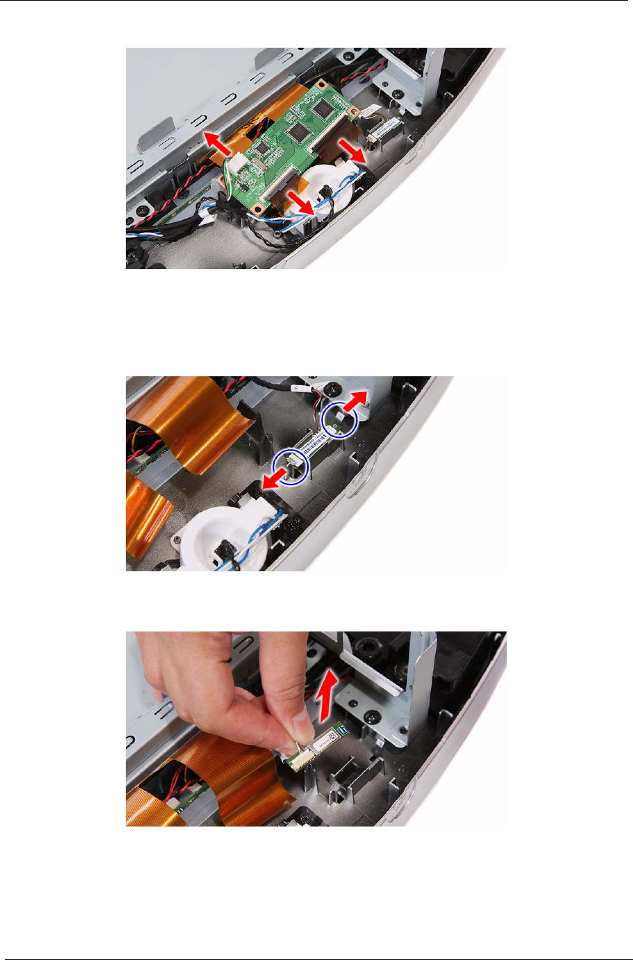
Removing the Bluetooth Module
1. Remove the PSU by following the procedure described on page 49.
2. Push the tabs securing the Bluetooth module.
3. Remove the Bluetooth module from the front bezel and turn it over to expose the cable connector
underneath it.
Packard Bell oneTwo M3350 / oneTwo M3351 / oneTwo L5350 / oneTwo L5351 Service Guide 53
4. Disconnect the Bluetooth cable from the module.
Removing the Power Button Assembly
1. Remove the PSU by following the procedure described on page 49.
2. Push the tabs securing the power button assembly.
3. Remove the power button assembly from the front bezel.
54 Packard Bell oneTwo M3350 / oneTwo M3351 / oneTwo L5350 / oneTwo L5351 Service Guide
Removing the LCD Assembly
1. Remove the I/O cable plate by following the procedure described on page 28.
2. Remove the optical drive by following the procedure described on page 29.
3. Remove the scaler board by following the procedure described on page 31
4. Remove the USB/audio board by following the procedure described on page 33.
5. Remove the mainboard by following the procedure described on page 47.
6. Remove the PSU by following the procedure described on page 49.
7. Disconnect the IR cable from the front bezel.
8. Disconnect the light bar cables from the light bars.
9. Remove the speakers.
Packard Bell oneTwo M3350 / oneTwo M3351 / oneTwo L5350 / oneTwo L5351 Service Guide 55
10. Disconnect the capacitive LED board cable.
11. Disconnect the webcam cable.
12. Remove the screws securing the main chassis.
Quantity Color Torque Part Number
5Black 4.0 kgf-cm 86.3AR26.8R0
56 Packard Bell oneTwo M3350 / oneTwo M3351 / oneTwo L5350 / oneTwo L5351 Service Guide
13. Push back the plastic snaps securing the LCD assembly to the front bezel.
14. Detach the LCD assembly from the front bezel.
Removing the Main Chassis
1. Remove the LCD assembly by following the procedure described on page 54.
2. Remove the screws securing the main chassis to the LCD module.
Quantity Color Torque Part Number
4Black 4.0 kgf-cm 86.00B75.240
Packard Bell oneTwo M3350 / oneTwo M3351 / oneTwo L5350 / oneTwo L5351 Service Guide 57
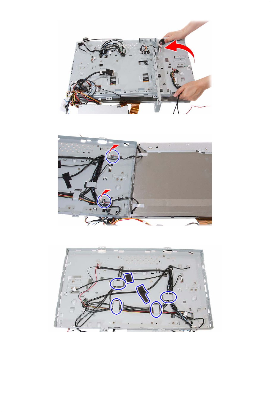
3. Remove the main chassis from the LCD module and lay it down beside the LCD module.
4. Release the inverter cables from the main chassis.
5. Remove the tapes securing the system cables, then release the cables from their main chassis latches.
58 Packard Bell oneTwo M3350 / oneTwo M3351 / oneTwo L5350 / oneTwo L5351 Service Guide
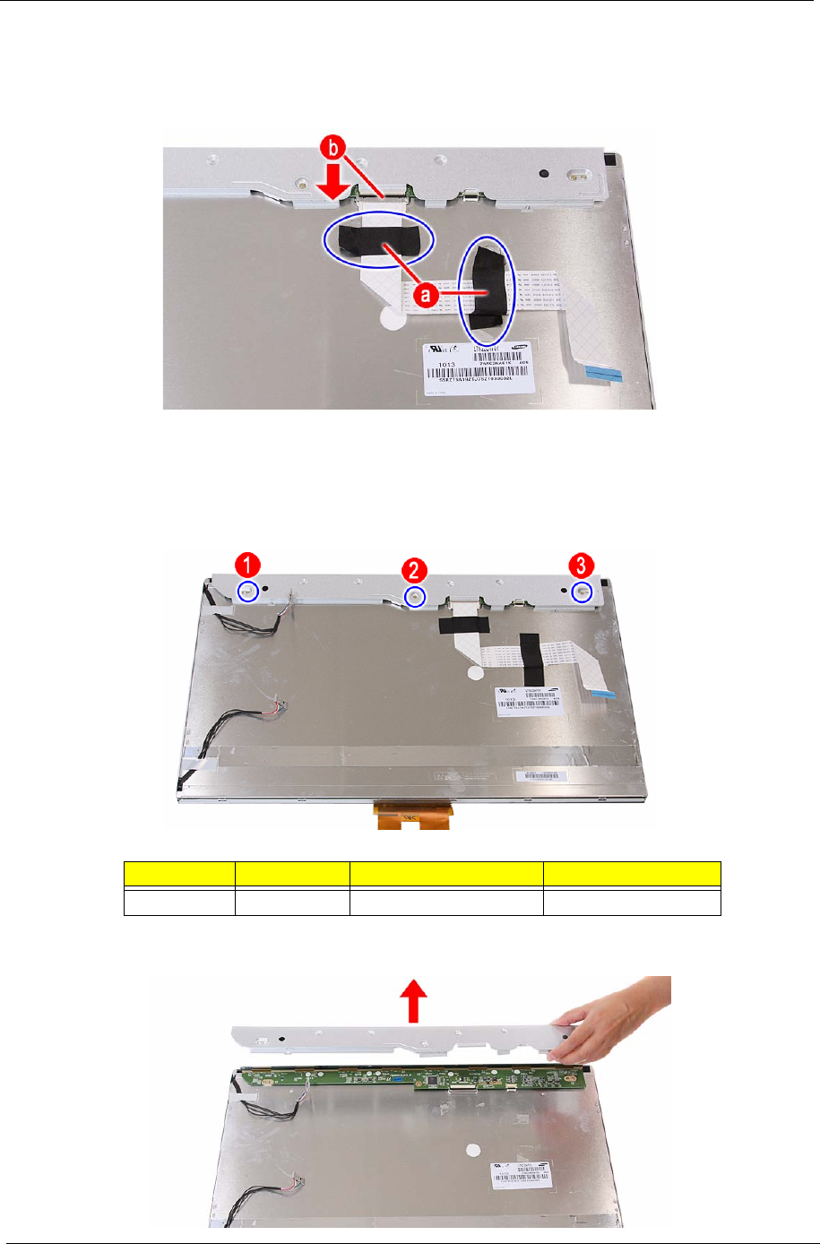
Removing the LCD Cable
1. Remove the main chassis by following the procedure described on page 56.
2. Remove the tapes securing the LCD cable (a), then disconnect the cable from the LCD board (b).
Removing the LCD Board Cover
1. Remove the main chassis by following the procedure described on page 56.
2. Remove the screws securing the LCD board cover.
3. Remove the LCD board cover.
Quantity Color Torque Part Number
3Silver – –
Packard Bell oneTwo M3350 / oneTwo M3351 / oneTwo L5350 / oneTwo L5351 Service Guide 59
Removing the Webcam Module
1. Remove the LCD assembly by following the procedure described on page 54.
2. Push the tabs securing the webcam module.
3. Push the tabs securing the webcam module, then remove the module from the front bezel.
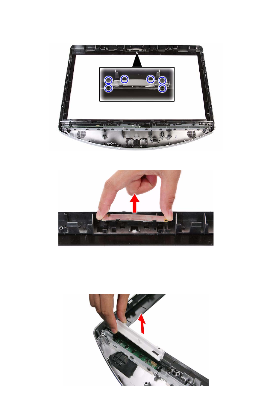
Removing the Capacitive LED Board
1. Remove the LCD assembly by following the procedure described on page 54.
2. Remove the capacitive LED board cover.
60 Packard Bell oneTwo M3350 / oneTwo M3351 / oneTwo L5350 / oneTwo L5351 Service Guide
3. Pry the capacitive LED board from the front bezel.
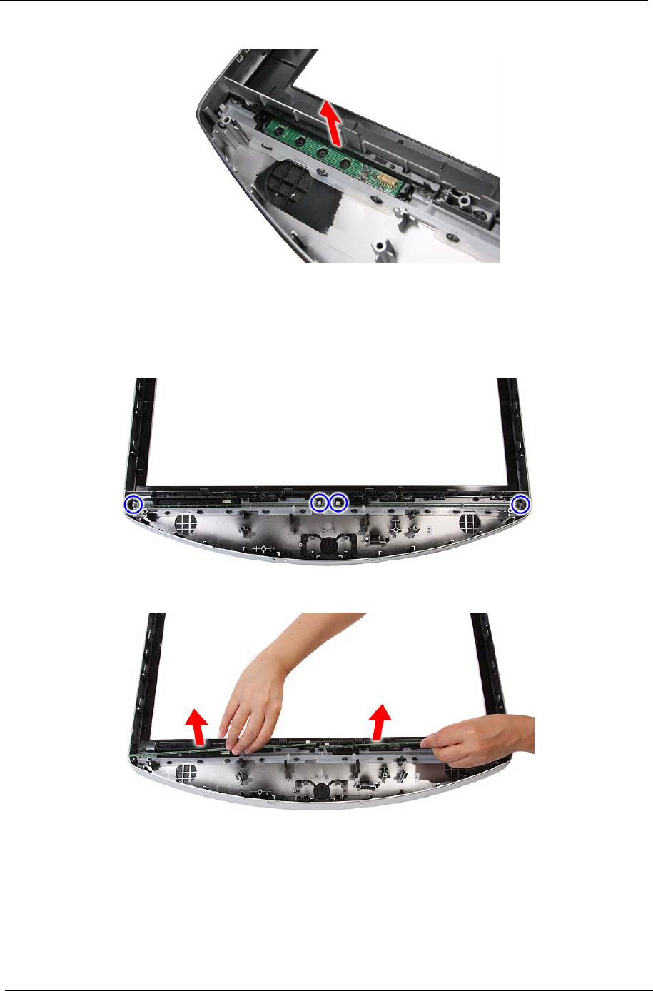
Removing the Light Bars
1. Remove the LCD assembly by following the procedure described on page 54.
2. Push the tabs securing both ends of the two light bars.
3. Remove the light bars from the front bezel.

Packard Bell oneTwo M3350 / oneTwo M3351 / oneTwo L5350 / oneTwo L5351 Service Guide 61
This chapter lists the POST error indicators and BIOS beep codes, as well general troubleshooting
instructions.
Hardware Diagnostic Procedure
1. Obtain as much detail as possible about the symptoms of the system failure.
2. Verify the symptoms by attempting to recreate the failure by running the diagnostic tests or repeating the
same operation.
3. Refer to “Power System Check” procedure on the next section and the “Beep Codes” section on page 76
to determine which corrective action to take.
System Check Procedures
Power System Check
If the system can be powered on, skip this section. Proceed to the “System Internal Inspection” procedure on
the next page.
If the system will not power on, do the following:
• Check if the power cable is properly connected to the AC power jack and a functional AC power source.
• Check if the voltage selector switch is set to the correct voltage setting.
System External Inspection
1. Inspect the power and LED indicators on the front panel. Go to “Front View” section on page 3 for the
location and description of the LED behaviour.
2. Make sure that the ventilation slots on the rear panel are not blocked.
3. Make sure that there is no point of contact in the system that can cause a power short.
If the cause of the failure is still can not be determined, perform the “System Internal Inspection”
procedure described on the next page.
IMPORTANT The diagnostic tests described in this chapter are only intended to test Acer products.
Non-Acer products, prototype cards, or modified options can give false errors and invalid
system responses.
Troubleshooting
Chapter 4

62 Packard Bell oneTwo M3350 / oneTwo M3351 / oneTwo L5350 / oneTwo L5351 Service Guide
System Internal Inspection
1. Turn off the power to the computer and all peripherals.
2. Unplug the power cord from the computer.
3. Unplug the network cable and all connected peripheral devices from the computer.
4. Place the computer on a flat, steady surface.
5. Remove the side panel as described in page 20.
6. Verify that the processor, memory module(s), and expansion board(s) are properly seated.
7. Verify that all power and data cables are firmly and properly attached to the installed drives.
8. Verify that all cable connections inside the system are firmly and properly attached to their appropriate
mainboard connectors.
9. Verify that all components are Acer-qualified and supported.
10. Reinstall the side panel.
11. Power on the system.
If the cause of the failure is still can not be determined, review the POST messages and BIOS
checkpoints during the system startup.
Checkpoints
A checkpoint is either a byte or word value output to I/O port 80h. The BIOS outputs checkpoints during
bootblock and Power-On Self Test (POST) to indicate the task the system is currently executing. Checkpoints
are very useful in aiding software developers or technicians in debugging problems that occur during the
pre-boot process.
Viewing BIOS Checkpoints
Viewing all checkpoints generated by the BIOS requires a checkpoint card, also referred to as a POST card or
POST diagnostic card. These are ISA or PCI add-in cards that show the value of I/O port 80h on a LED
display. Checkpoints may appear on the bottom right corner of the screen during POST. This display method is
limited, since it only displays checkpoints that occur after the video card has been activated.
Boot Block Initialization Code Checkpoints
The boot block initialization code sets up the chipset, memory, and other components before system memory
is available. The following table describes the type of checkpoints that may occur during the boot block
initialization portion of the BIOS.
NOTE Please note that checkpoints may differ between different platforms based on system
configuration. Checkpoints may change due to vendor requirements, system chipset or option
ROMs from add-in PCI devices.
Checkpoint Description
Before D1 Early chipset initialization is done. Early super I/O initialization is done including RTC and
keyboard controller. NMI is disabled.
D1 Perform keyboard controller BAT test. Check if waking up from power management
suspend state. Save power-on CPUID value in scratch CMOS.
D0 Go to flat mode with 4GB limit and GA20 enabled. Verify the bootblock checksum.
D2 Disable CACHE before memory detection. Execute full memory sizing module. Verify that
flat mode is enabled.
D3 If memory sizing module not executed, start memory refresh and do memory sizing in
bootblock code. Do additional chipset initialization. Re-enable CACHE. Verify that flat
mode is enabled.
D4 Test base 512 KB memory. Adjust policies and cache first 8 MB. Set stack.

Packard Bell oneTwo M3350 / oneTwo M3351 / oneTwo L5350 / oneTwo L5351 Service Guide 63
Boot Block Recovery Code Checkpoints
The boot block recovery code gets control when the BIOS determines that a BIOS recovery is required
because the user has forced the update or the BIOS checksum is corrupt. Refer to “BIOS Recovery” section
on page 77 for more information. The following table describes the type of checkpoints that may occur during
the boot block recovery portion of the BIOS.
D5 Bootblock code is copied from ROM to lower system memory and control is given to it.
BIOS now executes out of RAM.
D6 Both key sequence and OEM specific method is checked to determine if BIOS recovery is
forced. Main BIOS checksum is tested. If BIOS recovery is necessary, control flows to
checkpoint E0. See the “Boot Block Recovery Code Checkpoints” section for more
information.
D7 Restore CPUID value back into register. The Bootblock Runtime interface module is
moved to system memory and control is given to it. Determine whether to execute serial
flash.
D8 The Runtime module is uncompressed into memory. CPUID information is stored in
memory.
D9 Store the Uncompressed pointer for future use in PMM. Copying Main BIOS into memory.
Leaves all RAM below 1 MB Read-Write including E000 and F000 shadow areas but
closing SMRAM.
DA Restore CPUID value back into register. Give control to BIOS POST
(ExecutePOSTKernel). See the “POST Code Checkpoints” section for more information.
Checkpoint Description
E0 Initialize the floppy controller in the super I/O. Some interrupt vectors are initialized. DMA
controller is initialized. 8259 interrupt controller is initialized. L1 cache is enabled.
E9 Set up floppy controller and data. Attempt to read from floppy.
EA Enable ATAPI hardware. Attempt to read from ARMD and ATAPI CDROM.
EB Disable ATAPI hardware. Jump back to checkpoint E9.
EF Read error occurred on media. Jump back to checkpoint EB.
E9 or EA Determine information about root directory of recovery media.
F0 Search for pre-defined recovery file name in root directory.
F1 Recovery file not found.
F2 Start reading FAT table and analyze FAT to find the clusters occupied by the recovery file.
F3 Start reading the recovery file cluster by cluster.
F5 Disable L1 cache.
FA Check the validity of the recovery file configuration to the current configuration of the flash
part.
FB Make flash write enabled through chipset and OEM specific method. Detect proper flash
part. Verify that the found flash part size equals the recovery file size.
F4 The recovery file size does not equal the found flash part size.
FC Erase the flash part.
FD Program the flash part.
FF The flash has been updated successfully. Make flash write disabled. Disable ATAPI
hardware. Restore CPUID value back into register. Give control to F000 ROM at
F000:FFF0h.
Checkpoint Description

64 Packard Bell oneTwo M3350 / oneTwo M3351 / oneTwo L5350 / oneTwo L5351 Service Guide
POST Code Checkpoints
The POST code checkpoints are the largest set of checkpoints during the BIOS preboot process. The
following table describes the type of checkpoints that may occur during the POST portion of the BIOS.
Checkpoint Description
03 Disable NMI, Parity, video for EGA, and DMA controllers. Initialize BIOS, POST, Runtime
data area. Also initialize BIOS modules on POST entry and GPNV area. Initialized CMOS
as mentioned in the Kernel Variable "wCMOSFlags."
04 Check CMOS diagnostic byte to determine if battery power is OK and CMOS checksum is
OK. Verify CMOS checksum manually by reading storage area.
If the CMOS checksum is bad, update CMOS with power-on default values and clear
passwords. Initialize status register A.
Initializes data variables that are based on CMOS setup questions.
Initializes both the 8259 compatible PICs in the system
05 Initializes the interrupt controlling hardware (generally PIC) and interrupt vector table.
06 Do R/W test to CH-2 count reg. Initialize CH-0 as system timer.Install the POSTINT1Ch
handler. Enable IRQ-0 in PIC for system timer interrupt. Traps INT1Ch vector to
"POSTINT1ChHandlerBlock."
08 Initializes the CPU. The BAT test is being done on KBC. Program the keyboard controller
command byte is being done after Auto detection of KB/MS using AMI KB-5.
0A Initializes the 8042 compatible Key Board Controller.
0B Detects the presence of PS/2 mouse.
0C Detects the presence of Keyboard in KBC port.
0E Testing and initialization of different Input Devices. Also, update the Kernel Variables.
Traps the INT09h vector, so that the POST INT09h handler gets control for IRQ1.
Uncompress all available language, BIOS logo, and Silent logo modules.
13 Early POST initialization of chipset registers.
24 Uncompress and initialize any platform specific BIOS modules. GPNV is initialized at this
checkpoint.
30 Initialize System Management Interrupt.
2A Initializes different devices through DIM.
See DIM Code Checkpoints section for more information.
2C Initializes different devices. Detects and initializes the video adapter installed in the
system that have optional ROMs.
2E Initializes all the output devices.
31 Allocate memory for ADM module and uncompress it. Give control to ADM module for
initialization. Initialize language and font modules for ADM. Activate ADM module.
33 Initializes the silent boot module. Set the window for displaying text information.
37 Displaying sign-on message, CPU information, setup key message, and any OEM
specific information.
38 Initializes different devices through DIM. See DIM Code Checkpoints section for more
information. USB controllers are initialized at this point.
39 Initializes DMAC-1 & DMAC-2.
3A Initialize RTC date/time.
3B Test for total memory installed in the system. Also, Check for DEL or ESC keys to limit
memory test. Display total memory in the system.

Packard Bell oneTwo M3350 / oneTwo M3351 / oneTwo L5350 / oneTwo L5351 Service Guide 65
Checkpoint Description
3C Mid POST initialization of chipset registers.
40 Detect different devices (Parallel ports, serial ports, and coprocessor in CPU, ... etc.)
successfully installed in the system and update the BDA, EBDA…etc.
50 Programming the memory hole or any kind of implementation that needs an adjustment in
system RAM size if needed.
52 Updates CMOS memory size from memory found in memory test. Allocates memory for
Extended BIOS Data Area from base memory. Programming the memory hole or any kind
of implementation that needs an adjustment in system RAM size if needed.
60 Initializes Num-Lock status and programs the KBD typematic rate.
75 Initialize Int-13 and prepare for IPL detection.
78 Initializes IPL devices controlled by BIOS and option ROMs.
7A Initializes remaining option ROMs.
7C Generate and write contents of ESCD in NVRam.
84 Log errors encountered during POST.
85 Display errors to the user and gets the user response for error.
87 Execute BIOS setup if needed / requested. Check boot password if installed.
8C Late POST initialization of chipset registers.
8E Program the peripheral parameters. Enable/Disable NMI as selected.
90 Late POST initialization of system management interrupt.
A0 Check boot password if installed.
A1 Clean-up work needed before booting to OS.
A2 Takes care of runtime image preparation for different BIOS modules. Fill the free area in
F000h segment with 0FFh. Initializes the Microsoft IRQ Routing Table. Prepares the
runtime language module. Disables the system configuration display if needed.
A4 Initialize runtime language module. Display boot option popup menu.
A7 Displays the system configuration screen if enabled. Initialize the CPU’s before boot,
which includes the programming of the MTRR’s.
A8 Prepare CPU for OS boot including final MTRR values.
A9 Wait for user input at config display if needed.
AA Uninstall POST INT1Ch vector and INT09h vector. Deinitializes the ADM module.
AB Prepare BBS for Int 19 boot.
AC End of POST initialization of chipset registers.
B1 Save system context for ACPI.
00 Passes control to OS Loader (typically INT19h).

66 Packard Bell oneTwo M3350 / oneTwo M3351 / oneTwo L5350 / oneTwo L5351 Service Guide
DIM Code Checkpoints
The Device Initialization Manager (DIM) gets control at various times during BIOS POST to initialize different
system busses. The following table describes the main checkpoints where the DIM module is accessed.
POST Error Indicators
When a system error is detected during POST (Power On Self Text), the Setup utility will switch to diagnostic
mode and will either:
• Displays a POST error message, or
• Emits a series of beep codes
POST Error Messages
POST error messages tell users what failure the system has detected. Some error messages could be related
to a hardware device. Others may indicate a problem with a device configuration. In some cases an error
message may include recommendations for troubleshooting or require that you press the Enter key to display
recommendations. Follow the instructions on the screen. It is recommended that you correct the error before
proceeding, even if the computer appears to boot successfully.
Checkpoint Description
2A Initialize different buses and perform the following functions: Reset, Detect, and Disable
(function 0); Static Device Initialization (function 1); Boot Output Device Initialization
(function 2). Function 0 disables all device nodes, PCI devices, and PnP ISA cards. It also
assigns PCI bus numbers. Function 1 initializes all static devices that include manual
configured onboard peripherals, memory and I/O decode windows in PCI-PCI bridges,
and noncompliant PCI devices. Static resources are also reserved. Function 2 searches
for and initializes any PnP, PCI, or AGP video devices.
38 Initialize different buses and perform the following functions: Boot Input Device
Initialization (function 3); IPL Device Initialization (function 4); General Device Initialization
(function 5). Function 3 searches for and configures PCI input devices and detects if
system has standard keyboard controller. Function 4 searches for and configures all PnP
and PCI boot devices. Function 5 configures all onboard peripherals that are set to an
automatic configuration and configures all remaining PnP and PCI devices.
IMPORTANT If your system fails after you make changes in the Setup menus, reboot the computer, enter
Setup again and load Setup defaults to correct the error.

Packard Bell oneTwo M3350 / oneTwo M3351 / oneTwo L5350 / oneTwo L5351 Service Guide 67
Memory
Boot
Message Description
Gate20 Error The BIOS is unable to properly control the mainboard’s Gate A20 function, which
controls access of memory over 1 MB. This may indicate a problem with the
mainboard.
Multi-Bit ECC Error This message will only occur on systems using ECC enabled memory modules.
ECC memory has the ability to correct single-bit errors that may occur from faulty
memory modules.
A multiple bit corruption of memory has occurred, and the ECC memory algorithm
cannot correct it. This may indicate a defective memory module.
Parity Error Fatal Memory Parity Error. System halts after displaying this message.
RAM R/W test failed This message is displayed by the AMIBIOS8 when the RAM read/write test fails.
CMOS Memory Size
Wrong The base memory (memory below 1MB) size that is reported in the CMOS (offset
15h) mismatches with the actual size detected. This condition may occur when the
hole is set at 512K base memory or when CMOS is corrupted.
Message Description
Boot Failure... This is a generic message indicating the BIOS could not boot from a particular
device. This message is usually followed by other information concerning the
device.
Invalid Boot Diskette A diskette was found in the drive, but it is not configured as a bootable diskette.
Drive Not Ready The BIOS was unable to access the drive because it indicated it was not ready for
data transfer. This is often reported by drives when no media is present.
A: Drive Error The BIOS attempted to configure the A: drive during POST, but was unable to
properly configure the device. This may be due to a bad cable or faulty diskette
drive.
B: Drive Error The BIOS attempted to configure the B: drive during POST, but was unable to
properly configure the device. This may be due to a bad cable or faulty diskette
drive.
Insert BOOT diskette
in A: The BIOS attempted to boot from the A: drive, but could not find a proper boot
diskette.
Reboot and Select proper Boot device or Insert Boot Media in selected Boot device
BIOS could not find a bootable device in the system and/or removable media drive
does not contain media.
Reboot and select
proper boot device or
Insert boot media in
selected boot device
BIOS could not find a bootable device in the system and/or removable
media drive does not contain media.
NO ROM BASIC This message occurs on some systems when no bootable device can be detected.

68 Packard Bell oneTwo M3350 / oneTwo M3351 / oneTwo L5350 / oneTwo L5351 Service Guide
Storage Device
Message Description
Primary Master Hard
Disk Error The IDE/ATAPI device configured as Primary Master could not be properly
initialized by the BIOS. This message is typically displayed when the BIOS is trying
to detect and configure IDE/ATAPI devices in POST.
Primary Slave Hard
Disk Error The IDE/ATAPI device configured as Primary Slave could not be properly initialized
by the BIOS. This message is typically displayed when the BIOS is trying to detect
and configure IDE/ATAPI devices in POST.
Secondary Master
Hard Disk Error The IDE/ATAPI device configured as Secondary Master could not be properly
initialized by the BIOS. This message is typically displayed when the BIOS is trying
to detect and configure IDE/ATAPI devices in POST.
Secondary Slave
Hard Disk Error The IDE/ATAPI device configured as Secondary Slave could not be properly
initialized by the BIOS. This message is typically displayed when the BIOS is trying
to detect and configure IDE/ATAPI devices in POST.
3rd Master Hard Disk
Error The IDE/ATAPI device configured as Master in the 3rd IDE controller could not be
properly initialized by the BIOS. This message is typically displayed when the BIOS
is trying to detect and configure IDE/ATAPI devices in POST.
3rd Slave Hard Disk
Error The IDE/ATAPI device configured as Slave in the 3rd IDE controller could not be
properly initialized by the BIOS. This message is typically displayed when the BIOS
is trying to detect and configure IDE/ATAPI devices in POST.
4th Master Hard Disk
Error The IDE/ATAPI device configured as Master in the 4th IDE controller could not be
properly initialized by the BIOS. This message is typically displayed when the BIOS
is trying to detect and configure IDE/ATAPI devices in POST.
4th Slave Hard Disk
Error The IDE/ATAPI device configured as Slave in the 4th IDE controller could not be
properly initialized by the BIOS. This message is typically displayed when the BIOS
is trying to detect and configure IDE/ATAPI devices in POST.
5th Master Hard Disk
Error The IDE/ATAPI device configured as Master in the 5th IDE controller could not be
properly initialized by the BIOS. This message is typically displayed when the BIOS
is trying to detect and configure IDE/ATAPI devices in POST.
5th Slave Hard Disk
Error The IDE/ATAPI device configured as Slave in the 5th IDE controller could not be
properly initialized by the BIOS. This message is typically displayed when the BIOS
is trying to detect and configure IDE/ATAPI devices in POST.
6th Master Hard Disk
Error The IDE/ATAPI device configured as Master in the 6th IDE controller could not be
properly initialized by the BIOS. This message is typically displayed when the BIOS
is trying to detect and configure IDE/ATAPI devices in POST.
6th Slave Hard Disk
Error The IDE/ATAPI device configured as Slave in the 6th IDE controller could not be
properly initialized by the BIOS. This message is typically displayed when the BIOS
is trying to detect and configure IDE/ATAPI devices in POST.
Primary Master Drive
- ATAPI Incompatible The IDE/ATAPI device configured as Primary Master failed an ATAPI compatibility
test. This message is typically displayed when the BIOS is trying to detect and
configure IDE/ATAPI devices in POST.
Primary Slave Drive -
ATAPI Incompatible The IDE/ATAPI device configured as Primary Slave failed an ATAPI compatibility
test. This message is typically displayed when the BIOS is trying to detect and
configure IDE/ATAPI devices in POST.
Secondary Master
Drive - ATAPI
Incompatible
The IDE/ATAPI device configured as Secondary Master failed an ATAPI
compatibility test. This message is typically displayed when the BIOS is trying to
detect and configure IDE/ATAPI devices in POST.
Secondary Slave
Drive - ATAPI
Incompatible
The IDE/ATAPI device configured as Secondary Slave failed an ATAPI compatibility
test. This message is typically displayed when the BIOS is trying to detect and
configure IDE/ATAPI devices in POST.
3rd Master Drive -
ATAPI Incompatible The IDE/ATAPI device configured as Master in the 3rd IDE controller failed an
ATAPI compatibility test. This message is typically displayed when the BIOS is
trying to detect and configure IDE/ATAPI devices in POST.

Packard Bell oneTwo M3350 / oneTwo M3351 / oneTwo L5350 / oneTwo L5351 Service Guide 69
3rd Slave Drive -
ATAPI Incompatible The IDE/ATAPI device configured as Slave in the 3rd IDE controller failed an ATAPI
compatibility test. This message is typically displayed when the BIOS is trying to
detect and configure IDE/ATAPI devices in POST.
4th Master Drive -
ATAPI Incompatible The IDE/ATAPI device configured as Master in the 4th IDE controller failed an
ATAPI compatibility test. This message is typically displayed when the BIOS is
trying to detect and configure IDE/ATAPI devices in POST.
4th Slave Drive -
ATAPI Incompatible The IDE/ATAPI device configured as Slave in the 4th IDE controller failed an ATAPI
compatibility test. This message is typically displayed when the BIOS is trying to
detect and configure IDE/ATAPI devices in POST.
5th Master Drive -
ATAPI Incompatible The IDE/ATAPI device configured as Master in the 5th IDE controller failed an
ATAPI compatibility test. This message is typically displayed when the BIOS is
trying to detect and configure IDE/ATAPI devices in POST.
5th Slave Drive -
ATAPI Incompatible The IDE/ATAPI device configured as Slave in the 5th IDE controller failed an ATAPI
compatibility test. This message is typically displayed when the BIOS is trying to
detect and configure IDE/ATAPI devices in POST.
6th Master Drive -
ATAPI Incompatible The IDE/ATAPI device configured as Master in the 6th IDE controller failed an
ATAPI compatibility test. This message is typically displayed when the BIOS is
trying to detect and configure IDE/ATAPI devices in POST.
6th Slave Drive -
ATAPI Incompatible The IDE/ATAPI device configured as Slave in the 6th IDE controller failed an ATAPI
compatibility test. This message is typically displayed when the BIOS is trying to
detect and configure IDE/ATAPI devices in POST.
S.M.A.R.T. Capable
but Command Failed The BIOS tried to send a S.M.A.R.T. message to a hard disk, but the command
transaction failed.
This message can be reported by an ATAPI device using the S.M.A.R.T. error
reporting standard. S.M.A.R.T. failure messages may indicate the need to replace
the hard disk.
S.M.A.R.T.
Command Failed The BIOS tried to send a S.M.A.R.T. message to a hard disk, but the command
transaction failed.
This message can be reported by an ATAPI device using the S.M.A.R.T. error
reporting standard. S.M.A.R.T. failure messages may indicate the need to replace
the hard disk.
S.M.A.R.T. Status
BAD, Backup and
Replace
A S.M.A.R.T. capable hard disk sends this message when it detects an imminent
failure.This message can be reported by an ATAPI device using the S.M.A.R.T.
error reporting standard. S.M.A.R.T. failure messages may indicate the need to
replace the hard disk.
S.M.A.R.T. Capable
and Status BAD A S.M.A.R.T. capable hard disk sends this message when it detects an imminent
failure.
This message can be reported by an ATAPI device using the S.M.A.R.T. error
reporting standard. S.M.A.R.T. failure messages may indicate the need to replace
the hard disk.
Message Description

70 Packard Bell oneTwo M3350 / oneTwo M3351 / oneTwo L5350 / oneTwo L5351 Service Guide
Virus-related
System Configuration
Message Description
BootSector Write!! The BIOS has detected software attempting to write to a drive’s boot sector. This is
flagged as possible virus activity. This message will only be displayed if Virus
Detection is enabled in AMIBIOS setup.
VIRUS: Continue
(Y/N)? If the BIOS detects possible virus activity, it will prompt the user. This message will
only be displayed if Virus Detection is enabled in AMIBIOS setup.
Message Description
DMA-1 Error Error initializing primary DMA controller. This is a fatal error, often indication a
problem with system hardware.
DMA-2 Error Error initializing secondary DMA controller. This is a fatal error, often indication a
problem with system hardware.
DMA Controller Error POST error while trying to initialize the DMA controller. This is a fatal error, often
indication a problem with system hardware.
Checking NVRAM...
Update Failed BIOS could not write to the NVRAM block. This message appears when the FLASH
part is write-protected or if there is no FLASH part (System uses a PROM or
EPROM).
Microcode Error BIOS could not find or load the CPU Microcode Update to the CPU. This message
only applies to INTEL CPUs. The message is most likely to appear when a brand
new CPU is installed in a mainboard with an outdated BIOS. In this case, the BIOS
must be updated to include the Microcode Update for the new CPU.
NVRAM Checksum
Bad, NVRAM
Cleared
There was an error in while validating the NVRAM data. This causes POST to clear
the NVRAM data.
Resource Conflict More than one system device is trying to use the same non-shareable resources
(Memory or I/O).
NVRAM Ignored The NVRAM data used to store Plug’n’Play (PnP) data was not used for system
configuration in POST.
NVRAM Bad The NVRAM data used to store Plug’n’Play (PnP) data was not used for system
configuration in POST due to a data error.
Static Resource
Conflict Two or more Static Devices are trying to use the same resource space (usually
Memory or I/O).
PCI I/O conflict A PCI adapter generated an I/O resource conflict when configured by BIOS POST.
PCI ROM conflict A PCI adapter generated an I/O resource conflict when configured by BIOS POST.
PCI IRQ conflict A PCI adapter generated an I/O resource conflict when configured by BIOS POST.
PCI IRQ routing table
error BIOS POST (DIM code) found a PCI device in the system but was unable to figure
out how to route an IRQ to the device. Usually this error is causing by an
incomplete description of the PCI Interrupt Routing of the system.
Timer Error Indicates an error while programming the count register of channel 2 of the 8254
timer. This may indicate a problem with system hardware.
Refresh timer test
failed BIOS POST found that the refresh timer hardware failed to pass the Refresh
Retrace Test.
Interrupt Controller-1
error BIOS POST could not initialize the Master Interrupt Controller. This may indicate a
problem with system hardware.
Interrupt Controller-2
error
BIOS POST could not initialize the Slave Interrupt Controller. This may indicate a
problem with system hardware.

Packard Bell oneTwo M3350 / oneTwo M3351 / oneTwo L5350 / oneTwo L5351 Service Guide 71
CMOS
Miscellaneous
Message Displayed Description
CMOS Date/Time Not
Set The CMOS date and/or time are invalid. This error can be resolved by readjusting
the system time in AMIBIOS Setup.
CMOS Battery Low CMOS battery is low. This message usually indicates that the CMOS battery needs
to be replaced. It could also appear when the user intentionally discharges the
CMOS battery.
CMOS Settings
Wrong CMOS settings are invalid. This error can be resolved by using AMIBIOS Setup.
CMOS Checksum
Bad CMOS contents failed the Checksum check. Indicates that the CMOS data has
been changed by a program other than the BIOS or that the CMOS is not retaining
its data due to malfunction. This error can typically be resolved by using AMIBIOS
Setup.
Message Displayed Description
KBC BAT Test failed Keyboard controller BAT test failed. This may indicate a problem with keyboard
controller initialization.
Keyboard Error Keyboard is not present or the hardware is not responding when the keyboard
controller is initialized.
PS/2 Keyboard not
found PS/2 keyboard support is enabled in the BIOS setup but the device is not detected.
PS/2 Mouse not
found PS/2 mouse support is enabled in the BIOS setup but the device is not detected.
Keyboard/Interface
Error Keyboard controller failure. This may indicate a problem with system hardware.
Unlock Keyboard PS/2 keyboard is locked. User needs to unlock the keyboard to continue the BIOS
POST.
System Halted The system has been halted. A reset or power cycle is required to reboot the
machine. This message appears after a fatal error has been detected.
<INS> Pressed Indicates that <INS> key is pressed during the BIOS POST. The POST will load and
use default CMOS settings.
Password check
failed The password entered does not match the password set in the setup. This condition
may occur for both Supervisor and User password verification.
Unknown BIOS error.
Error code = 004Ah This message is displayed when ADM module is not present in the AMIBIOS8
ROM.
Unknown BIOS error.
Error code = 004Bh This message is displayed when language module is not present in the AMIBIOS8
ROM.
Floppy Controller
Failure Error in initializing legacy Floppy Controller.

72 Packard Bell oneTwo M3350 / oneTwo M3351 / oneTwo L5350 / oneTwo L5351 Service Guide
Index of Symptom-to-FRU Error Messages
To use the information in this section to diagnose a problem:
1. Find the error symptom in the left column.
2. If directed to a check procedure, replace the FRU indicated in the check procedure.
If no check procedure is indicated, the first Action/FRU item listed in the right column is the most likely
cause.
NOTE If you cannot find a symptom or an error in this list and the problem remains, see “Undetermined
Problems” on page 65.
Processor/Processor Fan-related Symptoms
Symptom/Error Action/FRU
Processor fan does not run but power
supply fan runs. • Ensure the system is not in power saving mode.
• With the system powered on, measure the voltage of the
processor fan connector. Its reading should be +12Vdc. If the
reading shows normal, but the fan still does not work, then
replace the heat sink fan.
• Mainboard
Processor test failed. • Processor
• Mainboard
NOTE Normally, the processor fan should be operative, and the processor clock setting should be exactly
set to match its speed requirement before diagnosing any processor problems.
Mainboard and Memory-related Symptoms
Symptom/Error Action/FRU
Memory test failed. • Memory module
• Mainboard
Incorrect memory size shown or repeated
during POST. • Insert the memory modules in the DIMM sockets properly,
then reboot the system.
• Memory module
• Mainboard
System works but fails to enter power
saving mode when the Power Management
Mode is set to Enabled.
• Enter CMOS Setup and load the default settings. In Windows
systems, check settings in Power Management Property of
the Control Panel.
• Reload software from Recovery CD.
Blinking cursor only; system does not work. • IDE drive connection/cables
• IDE disk drives
• See “Undetermined Problems”.
• Mainboard
NOTE Ensure the memory modules are installed properly and the contact leads are clean before
diagnosing any system problems.

Packard Bell oneTwo M3350 / oneTwo M3351 / oneTwo L5350 / oneTwo L5351 Service Guide 73
Hard Disk Drive-related Symptoms
Symptom/Error Action/FRU
Hard disk drive test failed. • Enter CMOS Setup and load the default settings.
• Hard disk drive cable
• Hard disk drive
• Mainboard
Hard disk drive cannot format completely. • Enter CMOS Setup and load the default settings.
• Hard disk drive cable
• Hard disk drive
• Mainboard
Hard disk drive has write error. • Enter CMOS Setup and load the default settings.
• Hard disk drive
Hard disk drive LED fails to light, but
system operates normally. • With the system power on, measure the voltage of the HDD
LED connector.
• HDD LED cable
NOTE Make sure the hard disk drive is configured correctly in CMOS Setup and that cable/jumper are set
correctly before diagnosing any hard disk drive problems. (If only one drive is installed, please
make sure the drive is connected to master connector or the drive is set to master.)
Optical Disc Drive-related Symptoms
Symptom/Error Action/FRU
CD/DVD-ROM drive LED doesn't come on
but works normally. • Enter CMOS Setup and load the default settings.
•DIMM
• Mainboard
CD/DVD-ROM drive LED flashes for more
than 30 seconds before LED shutting off.
Software asks to reinstall disc. Software
displays a reading CD/DVD error.
• CD/DVD-ROM may have dirt or foreign material on it. Check
with a known good disc.
• CD/DVD-ROM is not inserted properly.
• CD/DVD-ROM is damaged.
CD/DVD-ROM drive cannot load or eject
when the system is turned on and its eject
button is pressed and held.
• Disconnect all cables from CD/DVD-ROM drive except power
cable, then press the eject button to try to unload the disc.
• CD/DVD-ROM drive power cable
• CD/DVD-ROM drive
CD/DVD-ROM drive does not read and
there are no messages are displayed. • CD may have dirt or foreign material on it. Check with a
known good disc.
• Ensure the CD/DVD-ROM driver is installed properly.
• CD/DVD-ROM drive.
CD/DVD-ROM drive can play audio CD but
no sound output. • Ensure the headphone jack of the CD/DVD-ROM has an
output.
• Turn up the sound volume.
• Speaker power/connection/cable.
• CD/DVD-ROM drive.
NOTE Make sure the optical disc drive is configured correctly in CMOS Setup, the cable/jumper are set
correctly and the drive’s optical lens is clean before diagnosing any optical drive problems.

74 Packard Bell oneTwo M3350 / oneTwo M3351 / oneTwo L5350 / oneTwo L5351 Service Guide
Real-Time Clock-related Symptoms
Symptom/Error Action/FRU
Real-time clock is inaccurate. • Ensure the information in the Standard CMOS Feature of
BIOS Setup is set correctly.
• RTC battery
• Mainboard
Audio-related Symptoms
Symptom/Error Action/FRU
Audio software program invoked but no
sound comes from speakers. • Speaker power/connection/cable
Modem-related Symptoms
Symptom/Error Action/FRU
Modem ring cannot wake up system from
suspend mode. • For an external modem, make sure Power on By Ring in
BIOS Setup or Power Management is set to Enabled. For the
PCI modem, make sure Wake up by PCI card is set to
Enabled.
• If a PCI modem card is used, reinsert the modem card to the
PCI slot firmly or replace the modem card.
• In Win 98, ensure the telephone application is configured
correctly for your modem and set to receive messages and/or
fax.
Data/fax modem software program invoked
but cannot receive/send data/fax • Ensure the modem card is installed properly.
Fax/voice modem software program
invoked but has no sound output. (Data
files are received normally; voice from
modem cannot be produced, but system
sound feature works normally.)
• Ensure the modem voice-in cable from modem adapter card
is connected to the mainboard
Video and Monitor-related Symptoms
Symptom/Error Action/FRU
Video memory test failed.Video adapter
failed. • Remove all non-factory-installed cards.
• Load default settings (if screen is readable).
• Mainboard
Display problem
• Incorrect colors
• No high intensity
• Missing, broken, or incorrect characters
• Blank monitor (dark)
• Blank monitor (bright)
• Distorted image
• Unreadable monitor
• Monitor signal connection/cable
• Monitor
• Video adapter card
• Mainboard
Display changing colors. • Monitor signal connection/cable
• Video adapter card
• Mainboard

Packard Bell oneTwo M3350 / oneTwo M3351 / oneTwo L5350 / oneTwo L5351 Service Guide 75
Printer-related Symptoms
Symptom/Error Action/FRU
Printing failed. • Ensure the printer driver is properly installed. Refer to the
printer service manual.
• Printer
• Printer cable
• Mainboard.
Printer problems. • Refer to the service manual for the printer.
Keyboard-related Symptoms
Symptom/Error Action/FRU
Some or all keys on keyboard do not work. • Keyboard
Power Supply-related Symptoms
Symptom/Error Action/FRU
Pressing the power button does not turn off
the system. (Only unplugging the power
cord from electrical outlet can turn off the
system.)
• Ensure the Soft-off by PWR-BTTN in CMOS Setup (under
Power Management) is not set to Instant-off.
• Power switch cable assembly
Pressing the power button does not turn on
the system • Power switch cable assembly.
Executing software shutdown from
Windows98 Start menu does not turn off the
system. (Only pressing power button can
turn off the system).
• Enter CMOS Setup and load the default settings.
• Reload software from Recovery CD.
No system power, or power supply fan is
not running. • Power supply
• Mainboard

76 Packard Bell oneTwo M3350 / oneTwo M3351 / oneTwo L5350 / oneTwo L5351 Service Guide
Beep Codes
When no error message is displayed but the computer stops during POST, listen for beep codes.
Undetermined Problems
Follow the procedures below to isolate the failing FRU. Do not isolate non-defective FRU.
1. Power off the computer.
2. Visually check them for damage. If any problems are found, replace the FRU.
3. Remove or disconnect all of the following devices:
• Non-Acer devices
• Printer, mouse, and other external devices
• Hard disk drive
•DIMM
• CD/DVD-ROM drive
• Expansion boards
4. Power on the computer.
5. Determine if the problem has been resolved.
6. If the problem does not recur, reconnect the removed devices one at a time until you find the failed FRU.
If the problem persists, replace the mainboard, and then LCD assembly (one at a time). Do not replace a
non-defective FRU.
Beep Status Possible Causes
One short beep. System ready System is OK.
Continuous one
long beep Memory not installed or
memory error • Something is wrong with the memory installed
• There is problem accessing the memory (i.e., mainboard
problem)
One long beep, then
two short beeps and
repeat
VGA not installed or
VGA error • The mainboard can not access the video card for some
reasons. Either the video card is not working, its memory
is not accessible, or its BIOS may be corrupt.
• Something is wrong with the mainboard.
One long beep, then
one short beep BIOS failure BIOS damaged. Processor jump to boot block to execute
the default procedure.
Two short beeps. CMOS failure CMOS checksum error
NOTE • Verify that all attached devices are supported by the computer.
• Verify that the power supply being used at the time of the failure is operating correctly. (See
“Power System Check” on page 61)

Packard Bell oneTwo M3350 / oneTwo M3351 / oneTwo L5350 / oneTwo L5351 Service Guide 77
BIOS Recovery
When you boot up the computer and you hear one long beep, followed by a shorter one, the system BIOS is
damaged. This maybe cause by an interruption during a BIOS flash procedure (e.g. a power outage) or a
corrupted BIOS code, which will cause the system to go into an unbootable state.You need to access and
execute the boot block program to reboot the computer and recover the regular BIOS code.
Note the following when restoring the BIOS settings:
• Make sure the computer is connected to a UPS unit during the BIOS recovery process.
• The BIOS crisis recovery disk should be prepared in a computer running the Windows XP or Windows
Vista OS.
Creating the BIOS Crisis Recovery Disk
1. Prepare a removable USB storage device with a capacity size greater than 10 MB.
Note that all data on the USB storage device will be cleared during the creation of the crisis disk.
2. Set up a computer running the Windows XP or Windows Vista operating system and plug in the USB
storage device into an available USB port.
3. Copy the target BIOS ROM file to the USB storage device and rename it as “amiboot.rom”.
4. Unplug the USB storage device.
5. Eject the removable USB storage device from the computer.
Performing a BIOS Recovery
1. Shut down the BIOS failed-computer.
2. Connect the USB storage device containing the “amiboot.rom” file to the failed computer.
3. Press the power button to turn on the computer.
The system will now execute the BIOS recovery process. When the process is complete, four short beeps
will be emitted and the computer will automatically reboot.
4. Disconnect the USB storage device from the computer.
5. Press Delete to run the CMOS Setup Utility.
6. Press F9 to load the system default settings.
7. Select Ok, then press Enter.
8. Press F9 to save the default settings and close the Setup utility.
9. Select Ok, then press Enter.
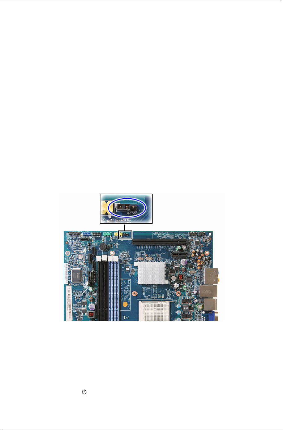
78 Packard Bell oneTwo M3350 / oneTwo M3351 / oneTwo L5350 / oneTwo L5351 Service Guide
Clearing CMOS
You may need to clear the Setup configuration values (CMOS) if the configuration has been corrupted, or if
incorrect settings made in the Setup Utility caused error messages to be unreadable. This procedure will clear
the BIOS supervisor password as well.
Use the JBIOS1 jumper to clear the CMOS data.
• 1-2 position: Normal operation (default)
• 2-3 position: Clear CMOS data
To clear the CMOS data:
1. Turn off the power to the computer and all peripherals.
2. Unplug the power cord from the computer.
3. Unplug the network cable and all connected peripheral devices from the computer.
4. Place the computer on a flat, steady surface with the rear cover facing upward.
5. Reinstall the rear cover by following the procedure described on page 28.
6. Remove the wall mount plate by following the procedure described on page 35.
7. Remove the graphics card by following the procedure described on page 37
8. Remove the hard drive by following the procedure described on page 40.
9. If necessary, remove any other assemblies or cables that prevent access to the CMOS clear jumper.
10. Locate the JBIOS1 jumper on the mainboard.
11. Remove the jumper block and set it over the 2-3 pins for 20 to 30 seconds.
12. Return the jumper block to its default 1-2 position.
13. Reinstall the hard drive, graphics card, and the wall mount plate.
14. Reinstall any any other assemblies or cables that have previously been removed.
15. Reinstall the rear cover and the computer stand.
16. Connect the AC power cord to the system.
17. Press the power button to turn on the computer.
18. During POST, press Delete to access the Setup Utility.
19. Press F9 to load the system default values.
20. Press F10 to save the changes you made and close the Setup Utility.
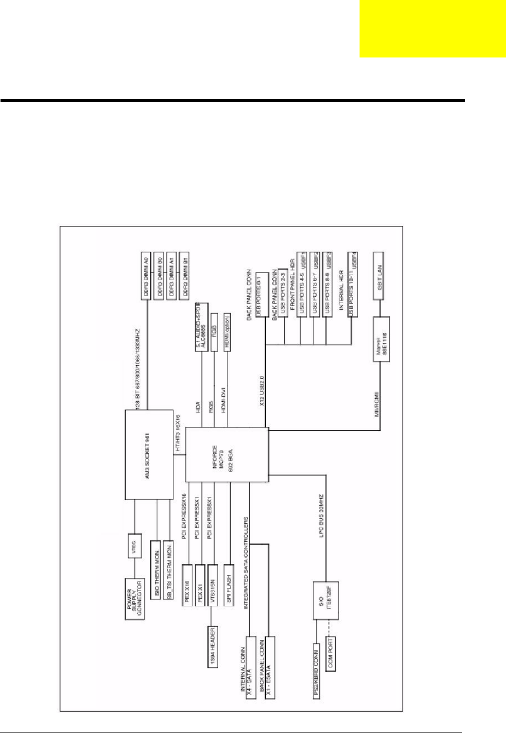
Packard Bell oneTwo M3350 / oneTwo M3351 / oneTwo L5350 / oneTwo L5351 Service Guide 79
This chapter shows the block diagram and board layout of the Packard Bell oneTwo M3350 / oneTwo M3351 /
oneTwo L5350 / oneTwo L5351 computer. Procedure for using the G116 hardware gap to clear the BIOS
password is also shown.
Block Diagram
The core subsystems of the Packard Bell oneTwo M3350 / oneTwo M3351 / oneTwo L5350 / oneTwo L5351
computer are depicted in the following block diagram.
System Architecture
Chapter 5
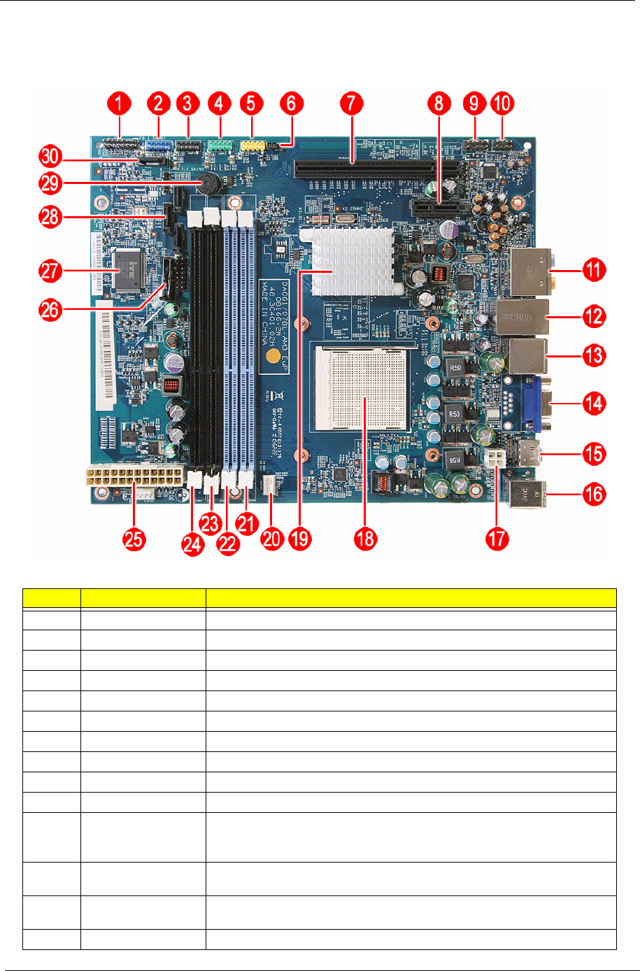
80 Packard Bell oneTwo M3350 / oneTwo M3351 / oneTwo L5350 / oneTwo L5351 Service Guide
Mainboard Layout
This section shows the major mainboard components.
Item Code Component
1LEDH1 Power button/LED cable connector
2USBF4 USB cable connector
3USBF3 Front I/O board cable connector
4USBF2 Front I/O board cable connector
5USBF1 Card reader function connector
6JBIOS1 Clear CMOS jumper
7PCIEX16 PCI Express x16 expansion slot (reserved for graphics card installation)
8PCIEX1 PCI Express x1 expansion slot (reserved for TV tuner card installation)
9AUDIOF1 Internal speaker cable connector
10 AUDIOS1 Side I/O board cable connector
11 AUDJACK1 Left panel audio jacks
Top: Line-in, line-out, and microphone jacks
Bottom: Line-in and line-out jacks
12 USBLAN1 Left: Ethernet port
Right: USB ports
13 USBESATA1 Left: USB ports
Right: eSATA port
14 VGA1 Monitor port

Packard Bell oneTwo M3350 / oneTwo M3351 / oneTwo L5350 / oneTwo L5351 Service Guide 81
15 HDMI1 HDMI port
16 KBMSCONN1 Left: PS/2 mouse port
Right: PS/2 keyboard port
17 PWR1 4-pin ATX power connector
18 U9 Processor socket
19 nVIDIA GeForce 8200 (MCP78PV) chipset
20 CPUFAN1 Heat sink fan cable connector
21 DIMM1 DDR3 slot 1
22 DIMM2 DDR3 slot 2
23 DIMM3 DDR3 slot 3
24 DIMM4 DDR3 slot 4
25 PWR2 24-pin ATX power connector
26 BT1 RTC battery
27 U22 SIO ITE 8720 controller
28 SATA3 ODD SATA cable connector
29 BZ1 Internal buzzer
30 SATA1 HDD SATA cable connector
Item Code Component

82 Packard Bell oneTwo M3350 / oneTwo M3351 / oneTwo L5350 / oneTwo L5351 Service Guide

Packard Bell oneTwo M3350 / oneTwo M3351 / oneTwo L5350 / oneTwo L5351 Service Guide 83
This chapter gives you the FRU (Field Replaceable Unit) listing of the Packard Bell oneTwo M3350 / oneTwo
M3351 / oneTwo L5350 / oneTwo L5351 computer global configurations. Refer to this list when ordering for
repair parts or for RMA (Return Merchandise Authorization).
IMPORTANT Part number changes will not be noted in this printed Service Guide. The part numbers listed
in this Service Guide may differ from those given to regional AUTHORIZED SERVICE
PROVIDERS. You MUST use the local FRU list provided by your regional office to order
FRU parts for repair and service of customer machines. Make sure that you are using the
most up-to-date information available on your regional web site or channel when ordering
FRU parts.
NOTE Follow the local government regulations, or the rules set by your regional office on how to return or
dispose of defective parts.
Field Replaceable Unit (FRU) List
Chapter 6
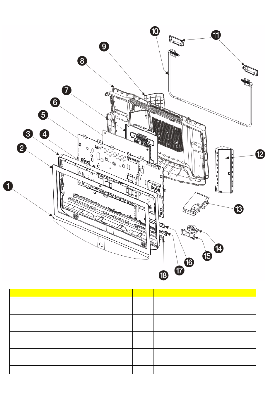
84 Packard Bell oneTwo M3350 / oneTwo M3351 / oneTwo L5350 / oneTwo L5351 Service Guide
Exploded Diagram
No. Component No. Component
1Speaker mesh plate 10 Computer stand
2Front bezel 11 Computer stand shells
3Front bezel frame 12 Inverter board cover
4Webcam module 13 USB/audio board cover
5Main chassis 14 Power button holder
6Mainboard 15 Power button knob
7Wall mount plate 16 Capacitive LED board cover
8Rear cover 17 Light bar guide
9I/O cable cover 18 Light bar cover
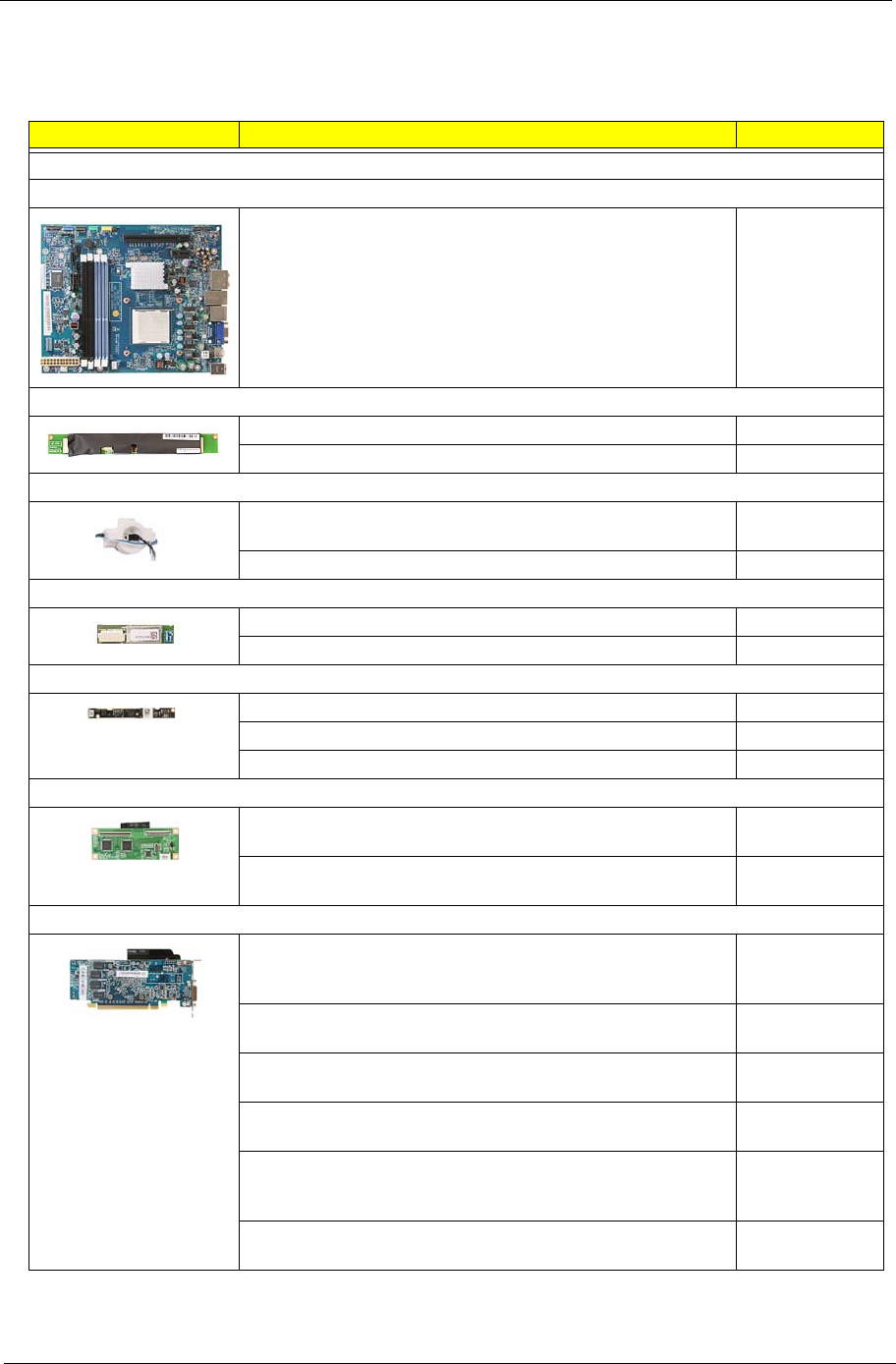
Packard Bell oneTwo M3350 / oneTwo M3351 / oneTwo L5350 / oneTwo L5351 Service Guide 85
FRU List
System Model: ACER_ONE TWO L5351_PGREENWOOD (No: 91.3CX01.A10G)
Category Part Name Part Number
Boards
Mainboard
MAINBOARD DA078L/ABOXER2 EUP W/RTC BATTERY W/O
1394 LF DDRIII 4 DIMM & CPU & MEMORY
MB.SE201.001
Inverter board
INVERTER BOARD 23" 4L DARFON VZ.13156.B01 19.21060.231
INVERTER BOARD 23" 4L SUMIDA IV30260SPEC139 19.21066.231
Power button assembly
CAPACITIVE BUTTON BOARD GALLAPHER-
TKSTWSGAL001
56.41010.491
CAPACITIVE BUTTON BOARD NS-GALLAGHER-CY 56.41010.511
Bluetooth module
BLUETOOTH BOARD LITEON WB111C-C1 V2.1+EDR 56.25034.021
BLUETOOTH BOARD XAVI BC10B-04C1 V2.1+EDR 56.25034.011
Webcam module
CAMERA 2M 1007 PARKORCHID C04PL037F 56.18007.521
CAMERA 2M CHICONY CNFA21321004590L 56.18022.521
CAMERA 2M PRIMAX 50-704A4WNT8 56.18009.521
Touchscreen control board
TOUCH CONTROL BOARD IDEACOM MUTI- IDC1650-114U0
RESISTIVE FOR 23
PA.14800.002
TOUCH CONTROL BOARD IDEACOM MUTI- IDC1650-114U0
RESISTIVE FOR 23
PA.14800.002
Graphics card
VGA CARD PCPARTNER 288-1E153-A00AC HD5450
512MB SDDR 3 (64BITS) SAMSUNG DVI HDMI W/LP BKT
ROHS 4 LAYER
VG.APC54.513
VGA CARD ECS 89D386-303408 HD5450 512MB (64BIT)
DDR3 DVI HDMI VGA LP BRACKET ROHS
VG.ECS54.511
VGA CARD ECS 89D386-469013 NV G315 512MB (64BIT)
DDR3 DVI HDMI LP BRACKET ROHS
VG.ECS31.5L1
VGA CARD PCPARTNER 288-1E145-A01AC HD5450 512MB
SDDR3 64BITS SAMSUNG DVI HDMI W/LP BRACKET ROHS
VG.APC54.511
VGA CARD PCPARTNER 288-2E142-A01AC ATI HD5570
1GB DDR 3 128BITS SAMSUNG DVI HDMI W/LP BRACKET
ROHS
VG.APC55.711
VGA CARD PCPARTNER 288-2E142-C01AC HD5570 1GB
128BITS SDDR3 DVI+HDMI LP (NEW HYNIX -1.2)
VG.APC55.732
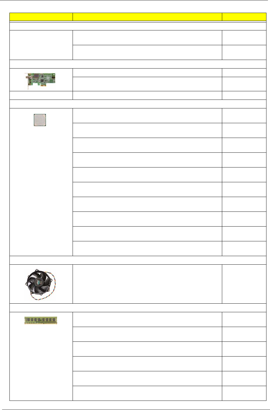
86 Packard Bell oneTwo M3350 / oneTwo M3351 / oneTwo L5350 / oneTwo L5351 Service Guide
Category Part Name Part Number
Graphics card (continuation)
VGA CARD PCPARTNER 288-5N118-A10AC NVIDIA GT320
1GB SDDR3 DVI+HDMI LP (SAMSUNG)
VG.PCPT3.211
VGA CARD PCPARTNER 288-5N118-C10AC NV GT320 1GB
DDR3 DVI+HDMI LP (HYNIX 1.2NS)
VG.PCPT3.213
TV tuner card
TV TUNER CARD AVERMEDIA H753-A ATSC TU.10500.064
TV TUNER CARD AVERMEDIA H753-D DVB-T TU.10500.065
Wireless LAN card WIRELESS LAN BOARD 802.11BGN LITE-ON WN6607LH NI.10200.041
Processor
CPU AMD ATHLON II X2 240 2.8GHZ 2M L2 CACHE 65W
REGOR
KC.AT202.240
CPU AMD ATHLON II X2 245 2.9GHZ 2M L2 CACHE 65W
REGOR
KC.AT202.245
CPU AMD ATHLON II X3 405E 2.3GHZ 1.5M L2 CACHE 45W
RANA ATHIIX3405E
KC.AE202.405
CPU AMD ATHLON II X4 600E 2.2GHZ 2M L2 CACHE 45W
PROPUS ATHIIX4600E
KC.AE202.600
CPU AMD ATHLON II X4 605E 2.3GHZ 2M L2 CACHE 45W
PROPUS ATHIIX4605E
KC.AE202.605
CPU AMD CPU ATHLON II X2 215 65W 2.7G
ADX215OCK22GQ
KC.AT202.215
CPU AMD P PHENOMII 910E AM3+ 2.6G 4X512K 4000 940
65W C-3 QUAD CORE
KC.PE202.910
CPU AMD PHENOMII X 3 700E 2.4GHZ 7.5M TOTAL CACHE
65W HEKA PHNMII700E
KC.PE202.700
CPU AMD PHENOMII X 3 705E 2.5GHZ 7.5M TOTAL CACHE
65W HEKA PHNMII705E
KC.PE202.705
CPU AMD PHENOMII X 4 900E 2.4GHZ 6M TOTAL CACHE
65W DENEB PHNMII900E
KC.PE202.900
Heat sink fan
CPU HEATSINK AIR COOLER LGA775 PGGREENWOOD HI.10800.079
Memory
MEMORY ADATA DDR3 1333MHZ 1G UNB-DIMM
AD63I1A0816EZ
KN.1GB07.002
MEMORY APACER DDR3 1333MHZ 1G UNB-DIMM
GU502203EP0201 LF 128*8 0.065UM
KN.1GB0B.036
MEMORY KINGSTON DDR3 1333MHZ 1G
ACR128X64D3U1333C9
KN.1GB01.031
MEMORY SAMSUNG DDR3 1333MHZ 1G UNB-DIMM
GU502203EP0201 LF 128*8 46NM
KN.1GB0F.005
MEMORY TRANSCEND DDR3 1333MH 1G UNB-DIMM
JM1333KLU-1G
KN.1GB0H.015
MEMORY UNIFOSA DDR3 1333MHZ 1G UNB-DIMM
GU502203EP0201 LF 128*8 0.065UM
KN.1GB0C.008
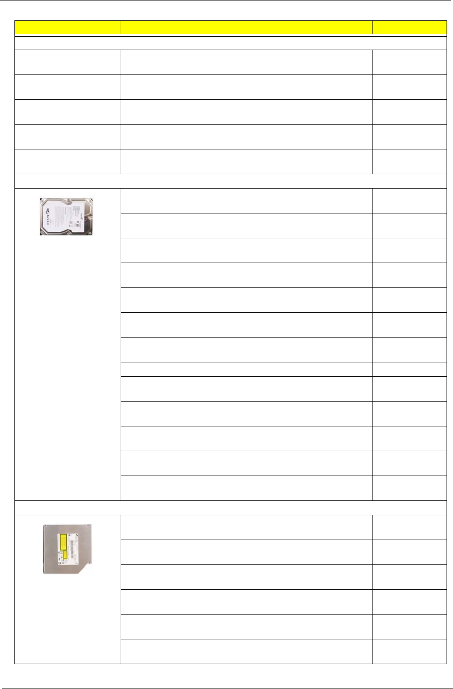
Packard Bell oneTwo M3350 / oneTwo M3351 / oneTwo L5350 / oneTwo L5351 Service Guide 87
Category Part Name Part Number
Memory (continuation)
MEMORY APACER DDR3 1333MHZ 2G UNB-DIMM LF 128*8
0.065UM
KN.2GB0B.024
MEMORY KINGSTON DDR3 1333MHZ 2G UNB
ACR256X64D3U1333C9
KN.2GB01.025
MEMORY SAMSUNG DDR3 1333MHZ 2G M378B5673FH0-
CH9
KN.2GB0F.004
MEMORY TRANSCEND DDR3 1333MHZ 2G UNB-DIMM
JM1333KLU-2G
KN.2GB0H.009
MEMORY UNIFOSA DDR3 1333MHZ 2G UNB-DIMM
GU512303EP0202 LF 128*8 0.065UM
KN.2GB07.002
Hard drive
HDD 320GB 3.5" 7200RPM SATA II 8MB HGST
HDT721032SLA380 SATURN
KH.32008.016
HDD 320GB 3.5" 7200RPM SATA II SEAGATE PHARAOH
8MB NCQ
KH.32007.006
HDD 320GB 3.5" 7200RPM SATA II WD WD3200AAJS-
22L7A0 XL320S
KH.32001.015
HDD 3.5" 500GB 7200RPM SATA WD XL320M WD5000AAKS-
22M9A0
KH.50008.014
HDD 640GB 3.5" 7200RPM HGST HDT721064SLA360
SATURN SATA
KH.64001.002
HDD 640GB 3.5" 7200RPM SATA II WD WD6400AAKS-
22A7B2 XL320-M
KH.64007.001
HDD 640GB 3.5" 7200RPM SEAGATE ST3640623AS BRINKS
SATA II 16MB LF
KH.64008.003
HDD 1TB 3.5" 5400RPM SATAII WD10EADS-22M4B0 8MB GP KH.01K08.005
HDD 1TB 3.5" 7200RPM SATA HGST SATURN
HDT721010SLA360
KH.01K01.007
HDD 1TB 3.5" 7200RPM WD XL333M SATA WD1001FALS-
22J7B0
KH.01K07.002
HDD 3.5" 1000GB 7200RPM SATA SEAGATE SEAGATE
ST31000528AS LF
KH.01K08.004
HDD 1.5TB 3.5" 5400RPM SATA WD GP500 WD15EADS-
22P8B0 32MB GP
KH.15K08.001
HDD 1.5TB 3.5" 7200RPM SATA SEAGATE BRINKS
ST31500341AS 32MB CC4H 7
KH.15K01.002
Optical drive
ODD HLDS BD COMBO 12.7MM TRAY DL 4X CT21N LF W/O
BEZEL 1.00 SATA FOR HF+WINDOWS7
KO.00407.004
ODD PANASONIC BD COMBO 12.7MM TRAY DL 4X
UJ141AL LF W/O BEZEL SATA FOR HF+WINDOWS7
KO.0040D.004
ODD PANASONIC BD RW 12.7MM TRLY DL4 4X UJ240A
SATA
KU.00407.015
ODD HLDS SUPER-MULTI DRIVE 12.7MM TRAY DL 8X
GT31N LF W/O BEZEL SATA FOR HF+WINDOWS7
KU.0080D.054
ODD HLDS SUPER-MULTI DRIVE 12.7MM TRAY DL 8X
GT31N LF W/O BEZEL SATA FOR HF+WINDOWS7
KU.0080F.014
ODD PLDS SUPER-MULTI DRIVE 12.7MM TRAY PLDS DS-
8A5SH LF W/O BEZEL SATA FOR HF+WINDOWS7
KU.0080D.054
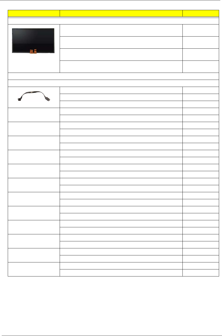
88 Packard Bell oneTwo M3350 / oneTwo M3351 / oneTwo L5350 / oneTwo L5351 Service Guide
Category Part Name Part Number
LCD panel
CCFL LCD LPL 23" WFHD NONE GLARE LM230WF1 TLA5
LF 300NIT 5MS G8
LK.23006.015
CCFL LCD SAMSUNG 23" WFHD NONE GLARE
LTM230HT01 A09 LF 300NIT 5MS 1000:1 HF
LK.23008.009
CCFL LCD SAMSUNG 23" WFHD NONE GLARE
LTM230HT01 A10 LF 300NIT 5MS 1000:1 HF
LK.23006.014
TOUCH PANEL 23" ETURBO SR-230M182235D1 23"
RESISTIVE MUTI-TOUCH PANEL TOUCH FILM
PC.14600.001
Cables
HDD SATA cable
HDD SATA CABLE 50.SAS01.001
HDD SATA CABLE 15PIN 50.3CM12.001
HDD SATA CABLE 15PIN 50.3CM30.001
ODD SATA cable ODD CABLE SATA 7+6PIN 50.3CM13.001
ODD CABLE SATA 7+6PIN 50.3CM31.001
Power button/LED cable POWER LED CABLE 50.3CM01.001
POWER LED CABLE 50.3CM20.001
USB/audio board cable USB BOARD CABLE 50.3CM03.001
USB BOARD CABLE 50.3CM22.001
Capacitive LED board
cable
FUNCTION KEY CABLE 50.3CM10.001
FUNCTION KEY CABLE 50.3CM29.001
Inverter cable INVERTER CABLE 23" WXGA 50.3CM08.001
INVERTER CABLE 23" WXGA 50.3CM27.001
Light bar cable LIGHT BAR CABLE 50.3CM09.001
LIGHT BAR CABLE 50.3CM28.001
Speaker cable SPEAKER CABLE 50.3CM07.001
SPEAKER CABLE 50.3CM26.001
Webcam cable CAMERA CABLE 50.3CM06.001
CAMERA CABLE 50.3CM25.001
Microphone cable FIO MIC CABLE 50.3CM02.001
FIO MIC CABLE 50.3CM21.001
Bluetooth cable BLUETOOTH CABLE 50.3CM11.001
BLUETOOTH CABLE 50.3CM15.001
Wireless LAN cable WIRELESS CR CABLE 50.3CM04.001
WIRELESS CR CABLE 50.3CM23.001
USB Bluetooth cable USB CABLE 50.3CM05.001
USB CABLE 50.3CM24.001
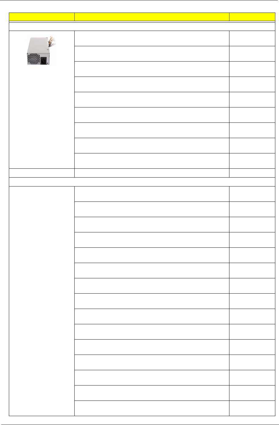
Packard Bell oneTwo M3350 / oneTwo M3351 / oneTwo L5350 / oneTwo L5351 Service Guide 89
Category Part Name Part Number
Power supply unit
POWER SUPPLY 220W CHICONYPOWER EPA CPB09-
D220E AAGASSI
PY.22009.008
POWER SUPPLY 220W CHICONYPOWER PFC CPB09-
D220A AAGASSI
PY.2200B.007
POWER SUPPLY 220W CHICONYPOWER REGULAR
CPB09-D220R AAGASSI
PY.22009.006
POWER SUPPLY 220W EUP 115VAC/230V NPFC DELTA
DPS-220UB A EUP
PY.2200B.006
POWER SUPPLY 220W FULL EPS5.0 DELTA DPS-220UB-2 B
EUP
PY.2200B.008
POWER SUPPLY 220W LITE-ON FULL PS-5221-9AE-ROHS
8.5L EUP 82+
PY.2200F.005
POWER SUPPLY 220W NPFC 115V/230V LITEON PS-5221-
06A1-ROHS EUP
PY.22009.007
POWER SUPPLY 220W PFC 230V DELTA DPS-220UB-1 A
EUP
PY.2200F.006
POWER SUPPLY 220W PFC 230V LITEON PE-5221-08AP-
ROHS EUP
PY.2200F.004
AC power cord POWER CORD 250V SOUTH AFRICA 27.01518.0Q1
Keyboard
KEYBOARD RF2.4 105 KEY CHICONY WUG0570 105KS
BLACK NORWEGIAN WITH PB LOGO
KB.RF403.195
KEYBOARD RF2.4 105 KEY CHICONY WUG0570 BLACK
ARABIC/ENGLISH
KB.RF403.212
KEYBOARD RF2.4 105 KEY CHICONY WUG0570 BLACK
BELGIUM WITH PB LOGO
KB.RF403.193
KEYBOARD RF2.4 105 KEY CHICONY WUG0570 BLACK
CZECH WITH PB LOGO
KB.RF403.204
KEYBOARD RF2.4 105 KEY CHICONY WUG0570 BLACK
DANISH WITH PB LOGO
KB.RF403.203
KEYBOARD RF2.4 105 KEY CHICONY WUG0570 BLACK
DUTCH WITH PB LOGO
KB.RF403.191
KEYBOARD RF2.4 105 KEY CHICONY WUG0570 BLACK
FRENCH WITH PB LOGO
KB.RF403.208
KEYBOARD RF2.4 105 KEY CHICONY WUG0570 BLACK
GERMAN WITH PB LOGO
KB.RF403.209
KEYBOARD RF2.4 105 KEY CHICONY WUG0570 BLACK
GREEK WITH PB LOGO
KB.RF403.202
KEYBOARD RF2.4 105 KEY CHICONY WUG0570 BLACK
HEBREW WITH PB LOGO
KB.RF403.196
KEYBOARD RF2.4 105 KEY CHICONY WUG0570 BLACK
HUNGARIAN WITH PB LOGO
KB.RF403.201
KEYBOARD RF2.4 105 KEY CHICONY WUG0570 BLACK
ICELANDIC WITH PB LOGO
KB.RF403.194
KEYBOARD RF2.4 105 KEY CHICONY WUG0570 BLACK
ITALIAN WITH PB LOGO
KB.RF403.189
KEYBOARD RF2.4 105 KEY CHICONY WUG0570 BLACK
NORDIC WITH PB LOGO
KB.RF403.210
KEYBOARD RF2.4 105 KEY CHICONY WUG0570 BLACK
POLISH WITH PB LOGO
KB.RF403.197

90 Packard Bell oneTwo M3350 / oneTwo M3351 / oneTwo L5350 / oneTwo L5351 Service Guide
Category Part Name Part Number
Keyboard (continuation)
KEYBOARD RF2.4 105 KEY CHICONY WUG0570 BLACK
PORTUGUESE WITH PB LOGO
KB.RF403.188
KEYBOARD RF2.4 105 KEY CHICONY WUG0570 BLACK
ROMANIAN WITH PB LOGO
KB.RF403.205
KEYBOARD RF2.4 105 KEY CHICONY WUG0570 BLACK
RUSSIAN WITH PB LOGO
KB.RF403.200
KEYBOARD RF2.4 105 KEY CHICONY WUG0570 BLACK
SLOVAK WITH PB LOGO
KB.RF403.199
KEYBOARD RF2.4 105 KEY CHICONY WUG0570 BLACK
SLOVENIAN WITH PB LOGO
KB.RF403.198
KEYBOARD RF2.4 105 KEY CHICONY WUG0570 BLACK
SPANISH WITH PB LOGO
KB.RF403.187
KEYBOARD RF2.4 105 KEY CHICONY WUG0570 BLACK
SWEDISH WITH PB LOGO
KB.RF403.190
KEYBOARD RF2.4 105 KEY CHICONY WUG0570 BLACK
SWISS/G WITH PB LOGO
KB.RF403.192
KEYBOARD RF2.4 105 KEY CHICONY WUG0570 BLACK
TURKISH WITH PB LOGO
KB.RF403.206
KEYBOARD RF2.4 105 KEY CHICONY WUG0570 BLACK UK
WITH PB LOGO
KB.RF403.207
KEYBOARD RF2.4 105 KEY CHICONY WUG0570 BLACK US
INTERNATIONAL WITH PB LOGO
KB.RF403.186
KEYBOARD USB 105 KEY CHICONY BLACK UK KB.USB03.268
KEYBOARD USB 105 KEY CHICONY KU-0420 BLACK
BELGIUM
KB.USB03.254
KEYBOARD USB 105 KEY CHICONY KU-0420 BLACK
CZECH
KB.USB03.265
KEYBOARD USB 105 KEY CHICONY KU-0420 BLACK
DANISH
KB.USB03.264
KEYBOARD USB 105 KEY CHICONY KU-0420 BLACK
DUTCH
KB.USB03.252
KEYBOARD USB 105 KEY CHICONY KU-0420 BLACK
FRENCH
KB.USB03.269
KEYBOARD USB 105 KEY CHICONY KU-0420 BLACK
GERMAN
KB.USB03.270
KEYBOARD USB 105 KEY CHICONY KU-0420 BLACK
GREEK
KB.USB03.263
KEYBOARD USB 105 KEY CHICONY KU-0420 BLACK
HEBREW
KB.USB03.257
KEYBOARD USB 105 KEY CHICONY KU-0420 BLACK
HUNGARIAN
KB.USB03.262
KEYBOARD USB 105 KEY CHICONY KU-0420 BLACK
ICELANDIC
KB.USB03.255
KEYBOARD USB 105 KEY CHICONY KU-0420 BLACK
ITALIAN
KB.USB03.250
KEYBOARD USB 105 KEY CHICONY KU-0420 BLACK
NORDIC
KB.USB03.271
KEYBOARD USB 105 KEY CHICONY KU-0420 BLACK
POLISH
KB.USB03.258

Packard Bell oneTwo M3350 / oneTwo M3351 / oneTwo L5350 / oneTwo L5351 Service Guide 91
Category Part Name Part Number
Keyboard (continuation)
KEYBOARD USB 105 KEY CHICONY KU-0420 BLACK
PORTUGUESE
KB.USB03.249
KEYBOARD USB 105 KEY CHICONY KU-0420 BLACK
ROMANIAN
KB.USB03.266
KEYBOARD USB 105 KEY CHICONY KU-0420 BLACK
RUSSIAN
KB.USB03.261
KEYBOARD USB 105 KEY CHICONY KU-0420 BLACK
SLOVAK
KB.USB03.260
KEYBOARD USB 105 KEY CHICONY KU-0420 BLACK
SLOVENIAN
KB.USB03.259
KEYBOARD USB 105 KEY CHICONY KU-0420 BLACK
SPANISH
KB.USB03.248
KEYBOARD USB 105 KEY CHICONY KU-0420 BLACK
SWISS/G
KB.USB03.253
KEYBOARD USB 105 KEY CHICONY KU-0420 BLACK
TURKISH
KB.USB03.267
KEYBOARD USB 105 KEY CHICONY KU-0420 BLACK US
INTERNATIONAL
KB.USB03.247
KEYBOARD USB 105 KEY CHICONY KU-0420 STANDARD
BLACK ARABIC/ENGLISH
KB.USB03.272
KEYBOARD USB 105 KEY CHICONY KU-0420 USB BLACK
SWEDISH
KB.USB03.251
KEYBOARD USB 105 KEY CHICONY KU-0420 USB
NORWEGIAN
KB.USB03.256
Mouse MOUSE RF2.4 CHICONY MG-0570T W MS.11200.062
MOUSE USB CHICONY MSU0960T-E93L MS.11200.061
Screws SCREW I NO6-32 L5 BZN 86.00J07.B60
SCREW NO4-40 L6.5 PAN NI 86.00N03.B40
SCREW PAN #6-32 L6 NI BOXER WZS 86.00J44.C60
Accessoriess
USB dongle receiver RECEIVER CHICONY DANGLE RECEIVER USB EXTERNAL RV.11000.022
Remote control REMOTE CONTROL PHILIPS RC2604301/01B MSFT CODE
PAIR WITH OVU430008 EMEA FOR WINDOWS7
RT.11300.023
REMOTE CONTROL PHILIPS RC2604302/01B MSFT CODE
PAIR WITH OVU430008 US FOR WINDOWS7
RT.11300.022
REMOTE CONTROL PHILIPS RC2604307/01BG PAIR WITH
RV.11000.007 EMEA FOR WINDOWS7
RT.11300.021
REMOTE CONTROL SMK RRS9003-3406E QUATRO PULSE
US WITH BATTERY PACK FOR WINDOWS7
RT.11300.025
REMOTE CONTROLLER PHILIPS RC2604701/01B MSFT
CODE JAPAN; PAIR WITH OVU430005 WINDOWS7
RT.11300.024
FRU items for part number updating
FRONT BOARD PGREENWOOD -1 FRONT BOARD DIP MP TBD
LIGHT BAR BOARD PGREENWOOD -1 LIGHT BAR BOARD DIP MP TBD
RISER BOARD FOR
SHORT VGA
PGREENWOOD -1 RISER FOR SHORT VGA DIP MP TBD
SCALER BOARD PGREENWOOD -1 SCALER BOARD DIP MP TBD
DVI TO D-SUB CABLE C.A. DVI TO D-SUB CABLE DTX_AIO TBD

92 Packard Bell oneTwo M3350 / oneTwo M3351 / oneTwo L5350 / oneTwo L5351 Service Guide
HDMI CABLE 600MM C.A. HDMI 600MM CABLE DTX AIO TBD
LVDS CABLE 23 "C.A LVDS CABLE 21_5 PG TBD
ASSY MB COVER
BRACKET PG
ASSY MB COVER BRACKET PG TBD
BACK COVER FOR 23 "ASSY BACK COVER PG TBD
FRONT BEZEL FOR 23 "ASSY FRONT BEZEL 23 PG TBD
FRONT IO BOARD
BRACKET
ASSY FRONT IO BRACKET PG TBD
FUNCTION KEY
COVER
CVR FUNCTION KEY COVER PG TBD
HDD BRACKET BRKT HDD BKT PG TBD
HLDR POWER
HOLDER PG
HLDR POWER HOLDER PG TBD
INVERTER BOARD
COVER
ASSY INVERTER COVER BKT PG TBD
MAIN CHASSIS FOR
GREENWOOD
ASSY MAIN CHASSIS PG TBD
ODD BEZEL ASSY ODD BEZEL RW PG TBD
ODD BRACKET BRKT ODD BRACKET PG TBD
POWER SUPPLY
BRACKET
BRKT PSU HOLDER BKT PG TBD
RISER CARD
BRACKET
BRKT RISER BKT PG TBD
SCALAR COVER
BRACKET
BRKT SCALAR COVER BKT PG TBD
WIRE COVER CVR WIRE COVER PG TBD
WIRE HOLDER HLDR WIRE HOLDER PG TBD
ANTENNA AUX WLAN
GALLAGHER ACON
ANTENNA AUX WLAN GALLAGHER ACON TBD
ANTENNA MAIN WLAN
GALLAGHER ACON
ANTENNA MAIN WLAN GALLAGHER ACON TBD
ASSEMBLY HINGE
MODULE FOOT
STAND
ASSY HINGE MODULE PG TBD
ASSEMBLY LCD
MODULE 23" WFHD
NONE GLARE
SAMSUNG W/TOUCH
PANEL&CONTRAL
BOARD& GLUE
ASSY LCD 23" SAMSUNG W/TP&BD TBD
GLUE FOR GLASS
PANEL LEFT AND
RIGHT 23
"GLUE GLASS PANEL L-R 23 PG TBD
Category Part Name Part Number

Packard Bell oneTwo M3350 / oneTwo M3351 / oneTwo L5350 / oneTwo L5351 Service Guide 93

Packard Bell oneTwo M3350 / oneTwo M3351 / oneTwo L5350 / oneTwo L5351 Service Guide 94
This chapter provides features summary for each of the Packard Bell oneTwo M3350 / oneTwo M3351 /
oneTwo L5350 / oneTwo L5351 computer model configurations.
Model Definitions and Configurations
Appendix A

95 Packard Bell oneTwo M3350 / oneTwo M3351 / oneTwo L5350 / oneTwo L5351 Service Guide
Packard Bell oneTwo M3351 / oneTwo L5351 Model Configuration
Common features
• Project name: gGreenwood
• Mainboard: Greenwood
WNMCP78PV_1394(N)_LOGO(N)_Eup(Y)
• DIMM1: U2GBIII13
• Card reader: Yes
Model Part No. Description Chassis Bezel CPU DIMM2 DIMM3 HDD ODD LCD VGA TV Tuner Add-on
Card 1 Add-on
Card 2 Keyboard Mouse Remote
Control PSU Power
Cord OS
oTL5351 PW.U5RE2
.001 oTL5351 CH
EMEA001
W7HP64PFR0206/
ATHIIX2215/2G*2/
500G*1/NSM8XS/
B23/315/802.11 b/g/n/
KB/mouse
HX093I PAIO1023 ATHIIX2
215 U2GBII
I13 ND500GB7
.2KS NSM8XS D23FHD Nvidia 315
512MB
HDMI/DVI
LP
N802.11 b/g/
n (mini-
card/
USB)(half
size) Kit
N N USB/
0420_PB USB/0420 PFC
220W
(8.5L) EuP
EU W7HP64
oTL5351 PW.U5RE2
.002 oTL5351 CH
EMEA001
W7HP64PFR0206/
ATHIIX2215/2G*2/
640G*1/NSM8XS/
B23/GT320/H753-D
Kit/802.11 b/g/n/
EMEA Win7 WMC/
KB/mouse
HX093I PAIO1023 ATHIIX2
215 U2GBII
I13 ND640GB7
.2KS NSM8XS D23FHD Nvidia
GT320
1GB
HDMI/DVI
LP
PCIe/SW/
DVB-T/
DTXAIO_Kit
802.11 b/g/
n (mini-
card/
USB)(half
size) Kit
NEMEA
Win7
WMC
USB/
0420_PB USB/0420 PFC
220W
(8.5L) EuP
EU W7HP64
oTL5351 PW.U5RE2
.009 oTL5351 CH
EMEA001
W7HP64RUPRU4407
/ATHIIX4605e/2G*2/
500G*1/NSM8XS/
B23/GT320/802.11 b/
g/n/KB/RF2.4/
0420_PB
HX093I PAIO1023 ATHIIX4
605e U2GBII
I13 ND500GB7
.2KS NSM8XS D23FHD Nvidia
GT320
1GB
HDMI/DVI
LP
N802.11 b/g/
n (mini-
card/
USB)(half
size) Kit
N N RF2.4/
0420_PB RF2.4/
0420_PB PFC
220W
(8.5L) EuP
EU W7HP64R
U
oTL5351 PW.U5RE2
.015 oTL5351 CH
EMEA001
W7HP64PDE0307/
ATHIIx2240/2G*2/
500G*1/NSM8XS/
B23/HD5450/H753-D
Kit/802.11 b/g/n/
EMEA Win7 WMC/
KB/RF2.4/0420_PB
HX093I PAIO1023 ATHIIx2
240 U2GBII
I13 ND500GB7
.2KS NSM8XS D23FHD ATI
HD5450
512MB
HDMI/DVI
LP
PCIe/SW/
DVB-T/
DTXAIO_Kit
802.11 b/g/
n (mini-
card/
USB)(half
size) Kit
NEMEA
Win7
WMC
RF2.4/
0420_PB RF2.4/
0420_PB PFC
220W
(8.5L) EuP
EU W7HP64
oTL5351 PW.U5RE2
.017 oTL5351 CH
EMEA001
W7HP64PNO9105/
ATHIIX4605e/2G*2/
1000G*1/NSM8XS/
B23/HD5570/802.11
b/g/n/KB/RF2.4/
0420_PB
HX093I PAIO1023 ATHIIX4
605e U2GBII
I13 ND1000GB
5.4KS NSM8XS D23FHD ATI
HD5570
1GB
HDMI/DVI
LP
N802.11 b/g/
n (mini-
card/
USB)(half
size) Kit
N N RF2.4/
0420_PB RF2.4/
0420_PB PFC
220W
(8.5L) EuP
EU W7HP64
oTL5351 PW.U5RE2
.036 oTL5351 CH
EMEA001
W7HP64RUPRU4407
/ATHIIX4605e/2G*2/
500G*1/NSM8XS/
B23/HD5570/802.11
b/g/n/KB/RF2.4/
0420_PB
HX093I PAIO1023 ATHIIX4
605e U2GBII
I13 ND500GB7
.2KS NSM8XS D23FHD ATI
HD5570
1GB
HDMI/DVI
LP
N802.11 b/g/
n (mini-
card/
USB)(half
size) Kit
N N RF2.4/
0420_PB RF2.4/
0420_PB PFC
220W
(8.5L) EuP
EU W7HP64R
U

Packard Bell oneTwo M3350 / oneTwo M3351 / oneTwo L5350 / oneTwo L5351 Service Guide 96
oTL5351 S1.U5R02.
001 oTL5351 Sample
EMEA001
W7HP64PIT0604/
PHNMII705e/2G*2/
640G*1/NBDRW4XS/
B23/EMEA Win7/
Philips/PS2/1688/
PS2Opt/PB
HX093I PAIO1023 PHNMII
705e NU2GBII
I13 D640GB7
.2KS NBDRW4
XS D23FHD N N N N EMEA
Win7/
Philips
PS2/1688 PS2Opt/
PB PFC
220W
(8.5L) EuP
EU W7HP64
oTM3351 PW.U5PE2
.001 oTM3351 CH
EMEA001
W7HP64PUK0108/
ATHIIX2250/
1G*1+2G*1/320G*1/
NSM8XS/D21.5H/
H753-D Kit/802.11 b/
g/n/EMEA Win7
WMC/KB/RF2.4/
0420_PB
HX093J PAIO1021 ATHIIX2
250 U2GBII
I13 ND320GB7
.2KS NSM8XS D21.5WU
XGA NPCIe/SW/
DVB-T/
DTXAIO_Kit
802.11 b/g/
n (mini-
card/
USB)(half
size) Kit
NEMEA
Win7
WMC
RF2.4/
0420_PB RF2.4/
0420_PB PFC
220W
(8.5L) EuP
UK W7HP64
oTM3351 PW.U5PE2
.002 oTM3351 CH
EMEA001
W7HP64PFR0206/
SMP140/2G*1/
320G*1/NSM8XS/
D21.5H/802.11 b/g/n/
KB/mouse
HX093J PAIO1021 SMP140 N N D320GB7
.2KS NSM8XS D21.5WU
XGA N N 802.11 b/g/
n (mini-
card/
USB)(half
size) Kit
N N USB/
0420_PB USB/0420 PFC
220W
(8.5L) EuP
EU W7HP64
oTM3351 PW.U5PE2
.003 oTM3351 CH
EMEA001
W7HP64PFR0206/
ATHIIX2215/
2G*1+1G*1/500G*1/
NSM8XS/D21.5H/
802.11 b/g/n/KB/
mouse
HX093J PAIO1021 ATHIIX2
215 U1GBII
I13 ND500GB7
.2KS NSM8XS D21.5WU
XGA N N 802.11 b/g/
n (mini-
card/
USB)(half
size) Kit
N N USB/
0420_PB USB/0420 PFC
220W
(8.5L) EuP
EU W7HP64
oTM3351 PW.U5PE2
.049 oTM3351 CH
EMEA001
W7HP64PES0407/
ATHIIX2215/2G*2/
1000G*1/NSM8XS/
D21.5H/315/H753-D
Kit/802.11 b/g/n/
Bluetooth/EMEA Win7
WMC/KB/RF2.4/
0420_PB
HX093J PAIO1021 ATHIIX2
215 U2GBII
I13 ND1000GB
5.4KS NSM8XS D21.5WU
XGA Nvidia 315
512MB
HDMI/DVI
LP
PCIe/SW/
DVB-T/
DTXAIO_Kit
802.11 b/g/
n (mini-
card/
USB)(half
size) Kit
Bluetooth
Kit EMEA
Win7
WMC
RF2.4/
0420_PB RF2.4/
0420_PB PFC
220W
(8.5L) EuP
EU W7HP64
oTM3351 PW.U5PE2
.050 oTM3351 CH
EMEA001
W7HP64PPOR1003/
ATHIIX2215/2G*2/
1000G*1/NSM8XS/
D21.5H/315/H753-D
Kit/802.11 b/g/n/
Bluetooth/EMEA Win7
WMC/KB/RF2.4/
0420_PB
HX093J PAIO1021 ATHIIX2
215 U2GBII
I13 ND1000GB
5.4KS NSM8XS D21.5WU
XGA Nvidia 315
512MB
HDMI/DVI
LP
PCIe/SW/
DVB-T/
DTXAIO_Kit
802.11 b/g/
n (mini-
card/
USB)(half
size) Kit
Bluetooth
Kit EMEA
Win7
WMC
RF2.4/
0420_PB RF2.4/
0420_PB PFC
220W
(8.5L) EuP
EU W7HP64
oTM3351 PW.U5PE2
.176 oTM3351 CH
EMEA001
W7HP64PCHB106/
ATHIIX2215/2G*2/
500G*1/NSM8XS/
D21.5H/H753-D Kit/
EMEA Win7 WMC/
KB/mouse
HX093J PAIO1021 ATHIIX2
215 U2GBII
I13 ND500GB7
.2KS NSM8XS D21.5WU
XGA NPCIe/SW/
DVB-T/
DTXAIO_Kit
N N EMEA
Win7
WMC
USB/
0420_PB USB/0420 PFC
220W
(8.5L) EuP
Swiss/EU W7HP64
Model Part No. Description Chassis Bezel CPU DIMM2 DIMM3 HDD ODD LCD VGA TV Tuner Add-on
Card 1 Add-on
Card 2 Keyboard Mouse Remote
Control PSU Power
Cord OS

97 Packard Bell oneTwo M3350 / oneTwo M3351 / oneTwo L5350 / oneTwo L5351 Service Guide
oTM3351 PW.U5PE2
.177 oTM3351 CH
EMEA001
W7HP64PFR0206/
ATHIIX2215/
2G*1+1G*1/500G*1/
NSM8XS/D21.5H/KB/
mouse
HX093J PAIO1021 ATHIIX2
215 U1GBII
I13 ND500GB7
.2KS NSM8XS D21.5WU
XGA N N N N N USB/
0420_PB USB/0420 PFC
220W
(8.5L) EuP
EU W7HP64
oTM3351 PW.U5PE2
.178 oTM3351 CH
EMEA001
W7HP64PFR0206/
ATHIIX2215/2G*2/
640G*1/NSM8XS/
D21.5H/802.11 b/g/n/
KB/mouse
HX093J PAIO1021 ATHIIX2
215 U2GBII
I13 ND640GB7
.2KS NSM8XS D21.5WU
XGA N N 802.11 b/g/
n (mini-
card/
USB)(half
size) Kit
N N USB/
0420_PB USB/0420 PFC
220W
(8.5L) EuP
EU W7HP64
oTM3351 PW.U5PE2
.180 oTM3351 CH
EMEA001
W7HP64RUPRU4407
/ATHIIx4600e/2G*2/
500G*1/NSM8XS/
D21.5H/GT320/802.11
b/g/n/KB/RF2.4/
0420_PB
HX093J PAIO1021 ATHIIx4
600e U2GBII
I13 ND500GB7
.2KS NSM8XS D21.5WU
XGA Nvidia
GT320
1GB
HDMI/DVI
LP
N802.11 b/g/
n (mini-
card/
USB)(half
size) Kit
N N RF2.4/
0420_PB RF2.4/
0420_PB PFC
220W
(8.5L) EuP
EU W7HP64R
U
oTM3351 PW.U5PE2
.181 oTM3351 CH
EMEA001
W7HP64PNO9105/
ATHIIX2215/
2G*1+1G*1/500G*1/
NSM8XS/D21.5H/
802.11 b/g/n/KB/
mouse
HX093J PAIO1021 ATHIIX2
215 U1GBII
I13 ND500GB7
.2KS NSM8XS D21.5WU
XGA N N 802.11 b/g/
n (mini-
card/
USB)(half
size) Kit
N N USB/
0420_PB USB/0420 PFC
220W
(8.5L) EuP
EU W7HP64
oTM3351 PW.U5PE2
.186 oTM3351 CH
EMEA001
W7HP64PFR0206/
ATHIIX2215/
2G*1+1G*1/320G*1/
NSM8XS/D21.5H/
H753-D Kit/802.11 b/
g/n/EMEA Win7
WMC/KB/mouse
HX093J PAIO1021 ATHIIX2
215 U1GBII
I13 ND320GB7
.2KS NSM8XS D21.5WU
XGA NPCIe/SW/
DVB-T/
DTXAIO_Kit
802.11 b/g/
n (mini-
card/
USB)(half
size) Kit
NEMEA
Win7
WMC
USB/
0420_PB USB/0420 PFC
220W
(8.5L) EuP
EU W7HP64
oTM3351 PW.U5PE2
.188 oTM3351 CH
EMEA001
W7HP64PDE0307/
ATHIIx2240/2G*2/
500G*1/NSM8XS/
D21.5H/KB/mouse
HX093J PAIO1021 ATHIIx2
240 U2GBII
I13 ND500GB7
.2KS NSM8XS D21.5WU
XGA N N N N N USB/
0420_PB USB/0420 PFC
220W
(8.5L) EuP
EU W7HP64
oTM3351 PW.U5PE2
.190 oTM3351 CH
EMEA001
W7HP64PNO9105/
ATHIIX2215/
2G*1+1G*1/500G*1/
NSM8XS/D21.5H/
HD5450/802.11 b/g/n/
KB/mouse
HX093J PAIO1021 ATHIIX2
215 U1GBII
I13 ND500GB7
.2KS NSM8XS D21.5WU
XGA ATI
HD5450
512MB
HDMI/DVI
LP
N802.11 b/g/
n (mini-
card/
USB)(half
size) Kit
N N USB/
0420_PB USB/0420 PFC
220W
(8.5L) EuP
EU W7HP64
oTM3351 PW.U5PE2
.192 oTM3351 CH
EMEA001
W7HP64PBEA703/
ATHIIX2215/2G*2/
500G*1/NSM8XS/
D21.5H/315/H753-D
Kit/802.11 b/g/n/
EMEA Win7 WMC/
KB/RF2.4/0420_PB
HX093J PAIO1021 ATHIIX2
215 U2GBII
I13 ND500GB7
.2KS NSM8XS D21.5WU
XGA Nvidia 315
512MB
HDMI/DVI
LP
PCIe/SW/
DVB-T/
DTXAIO_Kit
802.11 b/g/
n (mini-
card/
USB)(half
size) Kit
NEMEA
Win7
WMC
RF2.4/
0420_PB RF2.4/
0420_PB PFC
220W
(8.5L) EuP
EU W7HP64
Model Part No. Description Chassis Bezel CPU DIMM2 DIMM3 HDD ODD LCD VGA TV Tuner Add-on
Card 1 Add-on
Card 2 Keyboard Mouse Remote
Control PSU Power
Cord OS

Packard Bell oneTwo M3350 / oneTwo M3351 / oneTwo L5350 / oneTwo L5351 Service Guide 98
oTM3351 PW.U5PE2
.201 oTM3351 CH
EMEA001
W7HP64RUPRU4407
/ATHIIX3405e/
2G*1+1G*1/320G*1/
NSM8XS/D21.5H/
HD5450/802.11 b/g/n/
KB/RF2.4/0420_PB
HX093J PAIO1021 ATHIIX3
405e U1GBII
I13 ND320GB7
.2KS NSM8XS D21.5WU
XGA ATI
HD5450
512MB
HDMI/DVI
LP
N802.11 b/g/
n (mini-
card/
USB)(half
size) Kit
N N RF2.4/
0420_PB RF2.4/
0420_PB PFC
220W
(8.5L) EuP
EU W7HP64R
U
oTM3351 S1.U5P02.
001 oTM3351 Sample
EMEA001
W7HP64PNO9105/
PHNMII705e/2G*2/
640G*1/NSM8XS/
D21.5H/802.11 b/g/n/
KB/mouse
HX093J PAIO1021 PHNMII
705e U2GBII
I13 ND640GB7
.2KS NSM8XS D21.5WU
XGA N N 802.11 b/g/
n (mini-
card/
USB)(half
size)
N N USB/
0420_PB USB/0420 PFC
220W
(8.5L) EuP
EU W7HP64
Model Part No. Description Chassis Bezel CPU DIMM2 DIMM3 HDD ODD LCD VGA TV Tuner Add-on
Card 1 Add-on
Card 2 Keyboard Mouse Remote
Control PSU Power
Cord OS

99 Packard Bell oneTwo M3350 / oneTwo M3351 / oneTwo L5350 / oneTwo L5351 Service Guide

Packard Bell oneTwo M3350 / oneTwo M3351 / oneTwo L5350 / oneTwo L5351 Service Guide 100
This computer’s compatibility is tested and verified by Acer’s internal testing department. All of its system
functions are tested for both the Home Basic and Home Premium editions of Microsoft’s Windows Vista
operating system.
Refer to the following lists for components, adapter cards, and peripherals which have passed these tests.
Regarding configuration, combination and test procedures, please refer to the Packard Bell oneTwo M3350 /
oneTwo M3351 / oneTwo L5350 / oneTwo L5351 Vista Compatibility Test Report released by the Acer Mobile
System Testing Department.
Item Device Name Vendor
Access Point Air Station Wireless NFINITI [Model Num: WZR-G144N],
802.11n/g/b Buffalo
Buffalo Air Station NFINITI [ModeNum:WZR2-G300N],
802.11n/g/b Buffalo
Bluetooth Access
Point Bluetooth Access Point [ModeNum:BT300] X Bridge
Bluetooth Devices Bluetooth Stereo Headset [ModeNum:HT820] Motorola
Bluetooth Mouse [ModeNum:097855020512] Logitech
Motorola Bluetooth Wireless Headset H300 Motorola
Sony Ericsson Stereo Bluetooth Headset HBH-DS970 Sony
External LCD P243W 24-inch LCD Monitor Acer
P244W 24-inch LCD Monitor Acer
SP2208WFP 22-inch LCD Monitor Dell
UltraSharp 3008WFP 30-inch LCD Monitor Dell
2407FPW 24-inch LCD Monitor Dell
UltraSharp E2408WFP 24-inch Widescreen HDMI Dell
Earphone /
Microphone Hawk Stereo Headset 933 Hawk
Projector 3300MP Projector Dell
SIM Card FarEasTone 3G SIM Card FarEasTone
Chunghwa Telecom 3G SIM Card Chunghwa
Telecom
TV W37G (HDMI) Westinghouse
TC-37MPK (VGA/HDMI) Panasonic
USB 3G Card Huawei Mobile Connect E220 USB Modem 3G (E220:
HSDPA/UMTS/EDGE/GPRS/GSM) Huawei
USB Camera Canon Digital IXUS 860 IS Digital Compact Camera
(8.0 MP CCD sensor/DIGIC III with Face Detection AF/
AE/FE/28mm wide-angle lens with optical Image
Stabilizer, Media storage: SD, SDHC, MMC, MMCplus,
built-in SD 32 MB)
Canon
USB Storage Drive 6-in-1 Flash Card Reader/Writer PQI
Test Compatible Components
Appendix B

101 Packard Bell oneTwo M3350 / oneTwo M3351 / oneTwo L5350 / oneTwo L5351 Service Guide
Item Device Name Vendor
USB Flash Drive Transcend JetFlash USB 2.0 Flash Drive V85 8 GB
Memory Key Transcend
Apacer AH421 8 GB Apacer
A-Data PD16 Vista 16 GB A-Data
Transcend JetFlash USB 2.0 Flash Drive V10 16 GB
Memory Key Transcend
USB HDD 2.5-inch Portable 80 GB Hard Disk Transcend
USB ODD DVD+R/RW (USB 2.0) Plextor
USB Hub and Others Huawei Mobile Connect E220 USB Modem 3G (E220:
HSDPA/UMTS/EDGE/GPRS/GSM) Huawei
PowerSync USB2.0 4-Port Mini Hub (HU151W White) PowerSync
Techworks 4-Port USB2.0 Mini Hub (OW4PTUSBHB) Techworks
USB Keyboard/
Mouse First Wheel Mouse Logitech
Internet Navigator Keyboard Logitech
Dell L30U 0N242F USB Keyboard Dell
USB Printer HP Deskjet F4280 All-in-One: Printer/ Scanner/Copier,
1200x2400 dpi) HP
USB Speaker/
Joystick iFun USB Speaker (JS1200UA) JS
Dell USB Speaker Dell
Wireless Printer Photosmart C309 (CC35A) All-in-One Printer (4x6
photos/CD/DVD/Quick Forms, /Scanner/Copier/Fax)
Port: USB2.0/Ethernet/PictBridge/802.11g/BT
HP
Photosmart C4580 All-in-One Printer (4x6 photos) /
Scanner/Copier
Port: USB2.0/802.11g.b/Memory Card
HP
Memory Stick High Speed 1 GB Memory Stick Pro Duo Lexar
MS PRO Dou 2 GB High Speed Sony
MS PRO 2 GB Memory Card Sony
SanDisk Memory Stick Micro (M2) 8GB Card SanDisk
Multimedia Card RS-MMC 128MB Memory Card SanDisk
RS-MMC Mobile 256MB Memory Card PQI
Transcend MMC plus 4GB Card Transcend
Turbo 200X 2GB MMC Card A-DATA
SD Card 4GB SD PRO Memory Card RiDATA
SanDisk Multi-use SD Class 2 Memory Card 2GB SanDisk
SD Card 2 GB (150x Hi-Speed) Apacer
SanDisk MicroSDHC 4 GB Card with Adapter SanDisk
Kingston SDHC SD4 32 GB Card Kingston
xD Card Olympus xD-Picture Card M+ 2GB Speed Card Olympus
Fujifilm xD-Picture Card Type M 2 GB Fujifilm

Packard Bell oneTwo M3350 / oneTwo M3351 / oneTwo L5350 / oneTwo L5351 Service Guide 102
Approved Vendor List (AVL)
Component Vendor Description Model Part Number
Mainboard kit Wistron MB Kit oTM3350/3351_oTL5350/5351 nVidia MCP78PV
Proprietary W/O 1394 LF DDRIII 4 DIMM W/ EUP "Greenwood
WNMCP78PV_1394(N)_LOGO(N)_Eup(Y) MB.U5N01.001
Mainboard oTM3350/3351_oTL5350/5351 nVidia MCP78PV
Proprietary W/O 1394 LF DDRIII 4 DIMM W/ EUP "Greenwood
WNMCP78PV_1394(N)_LOGO(N)_Eup(Y) MB.U5N01.002
Front bezel Wistron Wistron PB Bezel PAIO1021 for 21.5" w/i HX093J chassis PAIO1021 PZ.11900.196
Wistron PB Bezel PAIO1023 for 23" w/i HX093I chassis PAIO1023 PZ.11900.195
Main chassis Wistron Wistron(LY) Chassis xSFF HX093I for AIO
GAIO_PAIO_1023 Bezel HX093I HS.13100.139
Wistron(LY) Chassis xSFF HX093J for AIO
GAIO_PAIO_1021 Bezel HX093J HS.13100.140
Heat sink fan CM CM iCooler LGA775 AIO DL5-8KDSA-R1-GP w/i pure al
25mm w/i 9225 fan for DTX AIO, 65W HI.10800.079
Processor AMD PhenomII 910e AM3+ 2.6G 4x512K 4000 940 65W C-3
Quad Core HD910EOCK4DGM KC.PE202.910
PhenomII x 4 900e 2.4GHz, 6M total cache 65W, Deneb,
PHNMII900e HD900EOCK4DGI KC.PE202.900
PhenomII x 3 705e 2.5GHz, 7.5M total cache 65W, Heka,
PHNMII705e HD705EOCK3DGI KC.PE202.705
PhenomII x 3 700e 2.4GHz, 7.5M total cache 65W, Heka,
PHNMII700e HD700EOCK3DGI KC.PE202.700
AthlonII 610e AM3+ 2.4G 4x512K 4000 940 45W C-3 Quad
Core AD610EHDK42GM KC.AM202.610
AMD Athlon II x4 605e 2.3G 512KB x4(45W) AD605EHDK42GI KC.AE202.605
Athlon II x4 600e 2.2GHz, 2M L2 cache 45W, Propus,
ATHIIX4600e AD600EHDK42GI KC.AE202.600
AthlonII 410e AM3+ 2.5G 3x512K 4000 940 45W C-3 Triple
Core AD410EHDK32GM KC.AM202.410
Athlon II x3 405e 2.3GHz, 1.5M L2 cache 45W, Rana,
ATHIIX3405e AD405EHDK32GI KC.AE202.405
AthlonII 255 AM3+ 2x1M 4000 940 65W C-2 3.1G, Dual
Core ADX255OCK23GM KC.AM202.255

103 Packard Bell oneTwo M3350 / oneTwo M3351 / oneTwo L5350 / oneTwo L5351 Service Guide
Athlon II x2 250 3.0GHz, 2M L2 cache 65W, Regor,
ATHIIX2250 ADX250OCK23GM KC.AM202.250
AMD Athlon II x2 245 2.9G 1Mx2 (65W) ADX245OCK23GQ KC.AT202.245
Athlon II x2 240 2.8GHz, 2M L2 cache 65W, Regor,
ATHIIX2240 ADX240OCK23GQ KC.AT202.240
Athlon II x2 215 2.7GHz 1M L2 cache 65W, Regor,
ATHIIX2215 ADX215OCK22GQ KC.AT202.215
Memory Unifosa DDRIII1333 GU502203EP0201 LF 128*8 0.065um KN.1GB0H.015
DDRIII1333 GU512303EP0202 LF 128*8 0.065um KN.2GB0H.009
Samsung DDRIII1333 M378B5673FH0-CH9 LF 128*8 46nm KN.2GB0B.024
DDRIII1333 M378B2873FHS-CH9 LF 128*8 46nm KN.1GB0B.036
Transcend DDRIII1333 JM1333KLU-1G KN.1GB0F.005
DDRIII1333 JM1333KLU-2G KN.2GB0F.004
Kingston DDRIII1333 ACR128X64D3U1333C9 LF 128*8 0.07um KN.1GB07.002
DDRIII1333 ACR256X64D3U1333C9 LF 128*8 0.07um KN.2GB07.002
Apacer DDRIII1333 75.073C1.G02 LF 128*8 0.065um KN.1GB01.031
DDRIII1333 75.A73C1.G02 LF 128*8 0.065um KN.2GB01.025
A-data DDRIII1333 AD63I1A0816EZ KN.1GB0C.008
Hard drive HGST 7200rpm 320GB HDT721032SLA380 Saturn KH.32007.006
7200rpm 640GB HDT721064SLA360 Saturn KH.64007.001
7200rpm 1000GB HDT721010SLA360 Saturn KH.01K07.002
WD 7200rpm 320GB WD3200AAJS-22L7A0 XL320S-3 KH.32008.016
7200rpm 500GB WD5000AAKS-22V1A0 SATA II 16MB LF
F/W:05.01D05 KH.50008.014
7200rpm 640GB WD6400AAKS-22A7B2 XL320M KH.64008.003
7200rpm 1000GB WD1001FALS-22J7B0 XL333 KH.01K08.004
5400rpm 1000GB WD10EADS-22M2B0 GP500 KH.01K08.005
5400rpm 1500GB WD15EADS-22P8B0 GP500 KH.15K08.001
Component Vendor Description Model Part Number

Packard Bell oneTwo M3350 / oneTwo M3351 / oneTwo L5350 / oneTwo L5351 Service Guide 104
Seagate 7200rpm 320GB ST3320418AS( Pharaoh) SATA II 16MB LF
F/W:CC44 Pharaoh KH.32001.015
7200rpm 640GB ST3640623AS(Brinks) SATA II 16MB LF F/
W:CC4H Brinks KH.64001.002
7200rpm 1000GB ST31000528AS(Pharaoh) SATA II 32MB
LF F/W:CC44 Pharaoh KH.01K01.007
7200rpm 1500GB ST31500341AS(Brinks) SATA II 32MB LF
F/W:CC4H Brinks KH.15K01.002
Optical drive HLDS ODD HLDS Super-Multi DRIVE 12.7mm Tray DL 8X GT31N KU.0080D.054
ODD HLDS BD COMBO 12.7mm Tray DL 4X CT21N KO.0040D.004
PLDS ODD PLDS Super-Multi DRIVE 12.7mm Tray DL 8X DS-8A5SH KU.0080F.014
Panasonic ODD PANASONIC BD COMBO 12.7mm Tray DL 4X UJ141AL KO.00407.004
ODD PANASONIC BD RW 12.7mm Tray DL 4X UJ240A KU.00407.015
TV tuner card AverMedia Avermedia H753-A TV Tuner Card PCIe Hybrid ATSC, S/W
Encoder H753-A TU.10500.064
Avermedia H753-D TV Tuner Card PCIe Hybrid DVB-T, S/W
Encoder H753-D TU.10500.065
Graphics card PCP NV GT320 1GB sDDR3 DVI+HDMI LP (SAMSUNG) VG.PCPT3.211
NV GT320 1GB DDR3 DVI+HDMI LP (HYNIX 1.2ns) VG.PCPT3.213
HD5570 1GB DDR 3 (128BITS) SAMSUNG DVI HDMI W/LP
BKT ROHS VG.APC55.711
HD5570 1GB 128bits sDDR3 DVI+HDMI LP (New Hynix -
1.2) VG.APC55.732
NV 315 512MB 64bits sDDR3 DVI+HDMI LP (New Hynix -
1.2) VG.PCPT3.164
HD5450 512MB SDDR 3 (64BITS) SAMSUNG DVI HDMI
W/LP BKT ROHS VG.APC54.511
HD5450 512MB SDDR 3 (64BITS) SAMSUNG DVI HDMI
W/LP BKT ROHS 4 LAYER VG.APC54.513
HD5450 512MB 64bits sDDR3 DVI+HDMI LP (New Hynix -
1.2) VG.APC54.532
HD5450 512MB 64bits sDDR3 DVI+HDMI LP 4 LAYER VG.APC54.534
Component Vendor Description Model Part Number

105 Packard Bell oneTwo M3350 / oneTwo M3351 / oneTwo L5350 / oneTwo L5351 Service Guide
ECS HD5450 512MB (64BIT) DDR3 DVI HDMI VGA LP
BRACKET ROHS VG.ECS54.511
NV G315 512MB (64BIT) DDR3 DVI HDMI LP BRACKET
ROHS VG.ECS31.5L1
WLAN module Lite-On Lite-On WN6607LH WLAN WN6607LH, Realtek
RTL8191SU, 802.11bgn 1Tx2R WLAN (mini-card)(USB
interface) Half Size
WN6607LH NI.10200.041
WLAN antenna ACON_Main ANTENNA MAN WLAN ACON Main AMM8P-700017 AMM8P-700017 25.91344.001
ACON_Aux ANTENNA AUX WLAN ACON_Aux AMM8P-700018 AMM8P-700018 25.91345.001
LCD panel with
touchscreen
function
eTurbo eTurbo 21.5" resistive muti-touch panel Panel touch film SR-215M181728D1 PC.14600.002
eTurbo 23" resistive muti-touch panel Panel touch film SR-230M182235D1 PC.14600.001
Touchscreen
control board Ideacom Ideacom Resistive muti-touch control board IDC1650-090U0
(for 21.5") IDC1650-090U0-01-00 PA.14800.001
Ideacom Resistive muti-touch control board IDC1650-114U0
(for 23") IDC1672-114U0-00-00 PA.14800.002
LCD panel AUO CCFL LCD AUO 21.5"W FHD None Glare M215HW01 V0
0G LF 300nit 5ms 1000:1 M215HW01 V0 Rev.0G LK.21505.011
CCFL LCD AUO 21.5"W FHD None Glare M215HW01 V0
0H LF 300nit 5ms 1000:1 M215HW01 V0 Rev.0H LK.21505.012
LGD CCFL LCD LPL 21.5"W FHD None Glare LM215WF1 TLF1
LF 300nit 5ms LM215WF1 LK.21508.006
SEC CCFL LCD SAMSUNG 23"W FHD None Glare
LTM230HT01 A09 LF 300nit 5ms 1000:1 HF LTM230HT01 LK.23006.014
CCFL LCD SAMSUNG 23"W FHD None Glare
LTM230HT01 A10 LF 300nit 5ms 1000:1 HF LTM230HT01 LK.23006.015
LGD CCFL LCD LPL 23"W FHD None Glare LM230WF1 TLA5 LF
300nit 5ms G8 LM230WF1 LK.23008.009
Component Vendor Description Model Part Number

Packard Bell oneTwo M3350 / oneTwo M3351 / oneTwo L5350 / oneTwo L5351 Service Guide 106
Power supply
unit Delta DPS-220UB A PY.22009.006 PY.22009.006
CP CPB09-D220R PY.2200F.004 PY.2200F.004
Delta DPS-220UB-1 A PY.22009.007 PY.22009.007
CP CPB09-D220A PY.2200F.005 PY.2200F.005
LiteOn PS-5221-9AE-RoHS (FR 220W, ES) PY.2200B.008 PY.2200B.008
Delta DPS-220UB-2 B (FR 220W, ES) PY.22009.008 PY.22009.008
CP CPB09-D220E (FR 220W, ES) PY.2200F.006 PY.2200F.006
Bluetooth module Chicony BT MODULE BT V2.1+EDR CSR BLUECORE4-PC-R BC10B-04C1 56.25034.021
Lite-on BT MODULE BT V2.1+EDR CSR BC04-ROM CSP A WB111C-C1-AA 56.25034.011
Webcam module
with microphone Chicony CAMERA 2M CNFA21321004590L CHICONY CNFA213 56.18007.521
Simplo CAMERA 2M 1007 C04PL037F PARKORCHID C04PL037F 56.18009.521
Inverter board Darfon INVERTER 4L VZ.13156.101 DARFON V156-B01 HF 19.21066.231
Sumida INVERTER 4L IV30260SPEC139 SUMIDA IV30260/T-LF 19.21060.231
Speakers Neosonica 5W_SPEAKER(L+R) 9C-032RA08K1P-01 DTX_AIO C032RA08K1P-01 23.40817.001
USB keyboard Chicony Keyboard CHICONY KU-0420 USB 105KS Black US
International KB.USB03.247
Keyboard CHICONY KU-0420 USB 105KS Black Spanish KB.USB03.248
Keyboard CHICONY KU-0420 USB 105KS Black
Portuguese KB.USB03.249
Keyboard CHICONY KU-0420 USB 105KS Black Italian KB.USB03.250
Keyboard CHICONY KU-0420 USB 105KS Black Swedish KB.USB03.251
Keyboard CHICONY KU-0420 USB 105KS Black Dutch KB.USB03.252
Keyboard CHICONY KU-0420 USB 105KS Black Swiss/G KB.USB03.253
Keyboard CHICONY KU-0420 USB 105KS Black Belgium KB.USB03.254
Keyboard CHICONY KU-0420 USB 105KS Black Icelandic KB.USB03.255
Keyboard CHICONY KU-0420 USB 105KS Black Norwegian KB.USB03.256
Keyboard CHICONY KU-0420 USB 105KS Black Hebrew KB.USB03.257
Keyboard CHICONY KU-0420 USB 105KS Black Polish KB.USB03.258
Keyboard CHICONY KU-0420 USB 105KS Black Slovenian KB.USB03.259
Component Vendor Description Model Part Number

107 Packard Bell oneTwo M3350 / oneTwo M3351 / oneTwo L5350 / oneTwo L5351 Service Guide
Keyboard CHICONY KU-0420 USB 105KS Black Slovak KB.USB03.260
Keyboard CHICONY KU-0420 USB 105KS Black Russian KB.USB03.261
Keyboard CHICONY KU-0420 USB 105KS Black Hungarian KB.USB03.262
Keyboard CHICONY KU-0420 USB 105KS Black Greek KB.USB03.263
Keyboard CHICONY KU-0420 USB 105KS Black Danish KB.USB03.264
Keyboard CHICONY KU-0420 USB 105KS Black Czech KB.USB03.265
Keyboard CHICONY KU-0420 USB 105KS Black Romanian KB.USB03.266
Keyboard CHICONY KU-0420 USB 105KS Black Turkish KB.USB03.267
Keyboard CHICONY KU-0420 USB 105KS Black UK KB.USB03.268
Keyboard CHICONY KU-0420 USB 105KS Black French KB.USB03.269
Keyboard CHICONY KU-0420 USB 105KS Black German KB.USB03.270
Keyboard CHICONY KU-0420 USB 105KS Black Nordic KB.USB03.271
Keyboard CHICONY KU-0420 USB Standard 105KS Black
Arabic/English KB.USB03.272
RF keyboard Chicony Keyboard CHICONY WUG0570 RF2.4 105KS Black US
International with PB logo KB.RF403.186
Keyboard CHICONY WUG0570 RF2.4 105KS Black
Spanish with PB logo KB.RF403.187
Keyboard CHICONY WUG0570 RF2.4 105KS Black
Portuguese with PB logo KB.RF403.188
Keyboard CHICONY WUG0570 RF2.4 105KS Black Italian
with PB logo KB.RF403.189
Keyboard CHICONY WUG0570 RF2.4 105KS Black
Swedish with PB logo KB.RF403.190
Keyboard CHICONY WUG0570 RF2.4 105KS Black Dutch
with PB logo KB.RF403.191
Keyboard CHICONY WUG0570 RF2.4 105KS Black Swiss/
G with PB logo KB.RF403.192
Keyboard CHICONY WUG0570 RF2.4 105KS Black
Belgium with PB logo KB.RF403.193
Component Vendor Description Model Part Number

Packard Bell oneTwo M3350 / oneTwo M3351 / oneTwo L5350 / oneTwo L5351 Service Guide 108
Keyboard CHICONY WUG0570 RF2.4 105KS Black
Icelandic with PB logo KB.RF403.194
Keyboard CHICONY WUG0570 RF2.4 105KS Black
Norwegian with PB logo KB.RF403.195
Keyboard CHICONY WUG0570 RF2.4 105KS Black Hebrew
with PB logo KB.RF403.196
Keyboard CHICONY WUG0570 RF2.4 105KS Black Polish
with PB logo KB.RF403.197
Keyboard CHICONY WUG0570 RF2.4 105KS Black
Slovenian with PB logo KB.RF403.198
Keyboard CHICONY WUG0570 RF2.4 105KS Black Slovak
with PB logo KB.RF403.199
Keyboard CHICONY WUG0570 RF2.4 105KS Black
Russian with PB logo KB.RF403.200
Keyboard CHICONY WUG0570 RF2.4 105KS Black
Hungarian with PB logo KB.RF403.201
Keyboard CHICONY WUG0570 RF2.4 105KS Black Greek
with PB logo KB.RF403.202
Keyboard CHICONY WUG0570 RF2.4 105KS Black Danish
with PB logo KB.RF403.203
Keyboard CHICONY WUG0570 RF2.4 105KS Black Czech
with PB logo KB.RF403.204
Keyboard CHICONY WUG0570 RF2.4 105KS Black
Romanian with PB logo KB.RF403.205
Keyboard CHICONY WUG0570 RF2.4 105KS Black Turkish
with PB logo KB.RF403.206
Keyboard CHICONY WUG0570 RF2.4 105KS Black UK with
PB logo KB.RF403.207
Keyboard CHICONY WUG0570 RF2.4 105KS Black French
with PB logo KB.RF403.208
Keyboard CHICONY WUG0570 RF2.4 105KS Black
German with PB logo KB.RF403.209
Keyboard CHICONY WUG0570 RF2.4 105KS Black Nordic
with PB logo KB.RF403.210
Component Vendor Description Model Part Number
109 Packard Bell oneTwo M3350 / oneTwo M3351 / oneTwo L5350 / oneTwo L5351 Service Guide
Keyboard dongle
receiver Chicony Chicony Dangle Receiver USB external receiver RV.11000.022
USB mouse Chicony Chicony optical mouse USB MSU0960 MS.11200.061
MCE remote
controller/
receiver
Philips Philips Remote Controller RC2604307/01BG for EMEA ;pair
with RV.11000.007 EMEA Win7/Philips RT.11300.021
Philips Remote Controller RC2604301/01B MSFT code
EMEA;pair with OVU430005 EMEA Win7 WMC RT.11300.023
Philips Remote Controller RC2604302/01B MSFT code
US;pair with OVU430005 US Win7 WMC RT.11300.022
Philips Remote Controller RC2604701/01B MSFT code
Japan; pair with OVU430005 US Win7 WMC RT.11300.024
SMK SMK Remote Controller US RRS9003-3406E SMK Quatro
Pulse;with Battery Pack US Win7 WMC_SMK RT.11300.025
Component Vendor Description Model Part Number

Packard Bell oneTwo M3350 / oneTwo M3351 / oneTwo L5350 / oneTwo L5351 Service Guide 110
This section describes online technical support services available to help you repair your Acer products.
If you are a distributor, dealer, ASP or TPM, please refer your technical queries to your local Acer branch
office. Acer branch offices and regional business units can access our website. However some information
sources will require a user ID and password. These can be obtained directly from Acer CSD Taiwan.
Acer's website offers you convenient and valuable support resources whenever you need them.
In the Technical Information section you can download information on all Acer notebook, desktop and server
models including:
• Service guides for all models
• User's manuals
• Training materials
• BIOS updates
• Software utilities
• Spare parts lists
• TABs (Technical Announcement Bulletin)
For these purposes, we have included a PDF file to facilitate the problem-free downloading of our technical
material.
Also available on this website are:
• Detailed information on Acer's International Traveler's Warranty (ITW)
• Returned material authorization procedures
• An overview of all the support services we offer, accompanied by a list of telephone, fax and email
contacts for all your technical queries.
We are always looking for ways to optimize and improve our services, so if you have any suggestions or
comments, please do not hesitate to communicate these to us.
Online Support Information
Appendix C

Packard Bell oneTwo M3350 / oneTwo M3351 / oneTwo L5350 / oneTwo L5351 Service Guide 111
A
AC power jack 4
ACPI, see Advanced Configuration Power
Interface 2
Advanced BIOS Features menu 16
Advanced Chipset Features menu 17
Advanced Configuration Power Interface
specifications 2
wake-up options 19
antivirus software 2
audio
headphone jack 5
line-in jack 4
line-out jack 4
microphone jack, left 4
microphone jack, right 5
specifications 9
troubleshooting 74
audio features 1
B
beep codes 76
BIOS
checkpoints 62
clear CMOS 78
crisis recovery disk 77
recovery 77
specifications 7
system passwords 22
version 14
BIOS Security Features menu 22
block diagram 79
Bluetooth
cable, part number 88
module, part number 85
module, remove 52
specifications 9
boot block
checkpoints 62
execute 77
boot sequence 16
brightness control keys 3
C
cable cover
location 4
capacitive keys 3
capacitive LED board
remove 59
card reader
location 4
supported cards 1
checkpoints
boot block 62
DIM 66
overview 62
POST 64
CMOS clear 78
CMOS Setup Utility
access 12
Advanced BIOS Features menu 16
Advanced Chipset Features menu 17
BIOS Security Features menu 22
Exit Without Saving 24
Frequency/Voltage Control menu 21
Integrated Peripherals menu 18
Load Default Settings 24
navigation keys 13
overview 11
PC Health Status menu 20
Power Management Setup menu 19
Product Information menu 14
Save & Exit Setup 24
Standard CMOS Features menu 15
computer stand
location 6
remove 26
connectivity
Bluetooth 9
Ethernet 9
WLAN 9
connectivity features 2
D
DIM checkpoints 66
disassembly procedures
Bluetooth module 52
capacitive LED board 59
computer stand 26
graphics card 37
guidelines 83
hard disk drive 40
heat sink fan 43
I/O cable cover 27
I/O cable plate 28
inverter board 42
inverter board bracket 37
LCD assembly 54
LCD board cover 58
LCD cable 58
light bars 60
main chassis 56
mainboard 47
memory 46
optical disc drive 29
power button assembly 53
power supply unit 49
preparatory steps 25
Index

112 Packard Bell oneTwo M3350 / oneTwo M3351 / oneTwo L5350 / oneTwo L5351 Service Guide
processor 44
rear cover 28
RTC battery 46
rubber feet 27
scaler board 31
tools 25
touchscreen control board 51
TV tuner card 36
USB/audio board 33
wall mount plate 35
webcam module 59
display
display by model 1
remove LCD assembly 54
remove LCD board cover 58
remove LCD cable 58
E
eSATA port 4
Ethernet
port location 4
specifications 9
Exit Without Saving menu 24
expansion slots
location 80
specifications 1
exploded view 84
F
Field Replaceable Unit, see FRU list 83
Frequency/Voltage Control menu 21
FRU list
components list 85
exploded view 84
part number updates 83
G
graphics card
part number 85
remove 37
H
hard disk drive
configuration 15
part number 87
remove 40
SATA connectors 81
specifications 8
troubleshooting 73
hardware
configuration utility 11
exploded view 84
FRU list 83
information display 14
model configurations 95
specifications 7
status monitoring 20
troubleshooting 61
HDD, see hard disk drive 1
HDMI port 4
headphone jack 5
heat sink fan
cable connector 81
part number 86
remove 43
HSF, see heat sink fan 43
I
I/O cable cover
remove 27
I/O cable plate
remove 28
I/O ports
listing 1
Integrated Peripherals menu 18
inverter board
bracket, remove 37
part number 85
remove 42
supported models 10
inverter cable
part number 88
K
keyboard
part number 89
L
LAN port
location 4
specifications 9
LCD board cover
remove 58
LCD cable
remove 58
LCD panel
part numbers 88
specifications 9, 10
light bars
cable, part number 88
remove 60
Load Default Settings menu 24
M
main chassis
remove 56
mainboard
component identification 80
part number 85
remove 47
specifications 2
troubleshooting 72
media storage 1
memory
check size 14
DIMM slots 81
part number 86
remove 46

Packard Bell oneTwo M3350 / oneTwo M3351 / oneTwo L5350 / oneTwo L5351 Service Guide 113
specifications 1, 8
troubleshooting 72
microphone jack
left 4
right 5
model configurations 95
modem board
troubleshooting 74
monitor port 4
mouse
part number 91
O
ODD bezel, remove 30
ODD, see optical disc drive 1
online support information 110
operating system 2
optical disc drive
bracket, remove 30
configuration 15
location 4
part number 87
remove 29
specifications 8
troubleshooting 73
OS support 2
P
part numbers
AC power cord 89
accessories 91
Bluetooth cable 88
Bluetooth module 85
graphics card 85
hard disk drive 87
HDD SATA cable 88
heat sink fan 86
inverter board 85
inverter cable 88
keyboard 89
LCD panel 88
light bar cable 88
mainboard 85
memory module 86
microphone cable 88
mouse 91
ODD SATA cable 88
optical disc drive 87
power button assembly 85
power button/LED cable 88
power supply unit 89
processor 86
screws 91
speaker cable 88
touchscreen control board 85
TV tuner card 86
USB Bluetooth cable 88
USB/audio board cable 88
webcam cable 88
webcam module 85
wireless LAN card 86
WLAN cable 88
PC Health Status menu 20
POST, see Power-On Self-Test 64
power
AC power jack 4
ACPI compliance 2
button assembly, part number 85
button assembly, remove 53
button/indicator 3
specifications 2
wake-up options 19
power management
configure 19
specifications 2
power supply unit
24-pin ATX connector 81
4-pin ATX connector 81
part number 89
remove 49
supported models 10
troubleshooting 75
Power-On Self-Test
beep codes 76
checkpoints 64
error messages 66
processor
check type/speed 14
part number 86
remove 44
socket 81
specifications 7
troubleshooting 72
Product Information menu 14
PS/2 keyboard port 4
PS/2 mouse port 4
PSU, see power supply unit 49
R
rear cover
remove 28
Return Merchandise Authorization 83
RMA, see Return Merchandise Authorization 83
RTC battery
BIOS error 11
location 81
remove 46
RTC clock
RTC battery 81
troubleshooting 74
rubber feet
remove 27

114 Packard Bell oneTwo M3350 / oneTwo M3351 / oneTwo L5350 / oneTwo L5351 Service Guide
S
Save & Exit Setup menu 24
scaler board
remove 31
security features 2
sepakers
location 3
serial-to-DVI port
cable, remove 47
location 4
soeakers
cable, part number 88
software specifications
operating system 2
speakers
remove 54
specifications
antivirus 2
audio 9
BIOS 7
Bluetooth 9
display 9, 10
Ethernet controller 9
hard disk drive 8
memory 8
optical disc drive 8
power supply unit 10
processor 7
system chipsets 7
webcam 9
WLAN controller 9
Standard CMOS Features menu 15
supervisor password 22
system architecture 79
system chipset 1
system chipsets 7
system date 15
system dimensions 2
system passwords
change 23
remove 23
set 23
system time 15
system views
front view 3
left view 4
rear view 6
right view 5
T
temperature
monitoring 20
touchscreen
by model 10
control board, part number 85
control board, remove 51
troubleshooting
BIOS checkpoints 62
BIOS recovery 77
clearing CMOS 78
component failure 72
hardware diagnostic procedure 61
online support information 110
POST error indicators 66
TV tuner card
part number 86
remove 36
U
undetermined problems 76
USB ports
bootable device 18
left 4
legacy device 18
right 5
USB/audio board
cable, part number 88
remove 33
user password 22
V
VGA port 4
video
troubleshooting 74
volume control keys 3
W
wall mount option 6
wall mount plate
remove 35
webcam
cable, part number 88
location 3
module, part number 85
module, remove 59
specifications 9
wireless LAN
cable, part number 88
card, part number 86
WLAN
specifications 9
