PaloSanto Solutions MINIUCS Elastix miniUCS User Manual IPC110
PaloSanto Solutions Elastix miniUCS IPC110
Manual

1/11
IPC110
IPC110IPC110
IPC110
Motherboard
Motherboard Motherboard
Motherboard User Manual
User ManualUser Manual
User Manual
Introduction
IPC110 series CPU boards are small form factor system boards optimized for PBX
and network security applications. With intel latest Z500P series processor,it is easy to
develop a Fanless system which has more reliability .Integrated up to 3 ethenet ,IPC110
provide a flexible application for customer. A typical PBX application is , attaching PCIe
voice card, to build total solution for little company communication. Or attaching
MiniPCIe network card, to build up to 5 network port firewall device.
Specification
• CPU: Intel Atom Z510P 1.1GHz/ Z520P 1.3GHz /Z530P 1.6GHz
• DRAM: Slot Onboard, up to 2GB DDR2 400/533 SDRAM (double side 1GB)
• Chipset: Intel Poulsbo
• SouthBridge: Poulsbo integrated
• Storage: CompactFlash socket, 44pin PATA connector,1 SATA slot
• Power: DC jack ,DC 12V
• Three front panel LEDs, for 3 programmable GPO status indicator
• Push button:for mode setting switch, accessing a programmable GPI, active low
means switch is pressed
• PCIe
Interface : PCIe x4 Golden Finger
• Expansion: 2 MiniPCIe slot
• Connectivity: Up to 3 Ethernet channels (10/100/1000Mbps speed)
3 PCIe Ethernet controller
Support PXE (for remote booting )
• I/O: 1*DB9 serial port, for debug console usage ,RS232, 3*USB 2.0 port
• Board size: 6 x 6" (152.4 x 152.4 mm)
• Firmware: AMI BIOS
Operating system compatibility
1、Windows 2000/XP
2、Linux
3、DOS
2/11
IPC110 Connector and Jumper
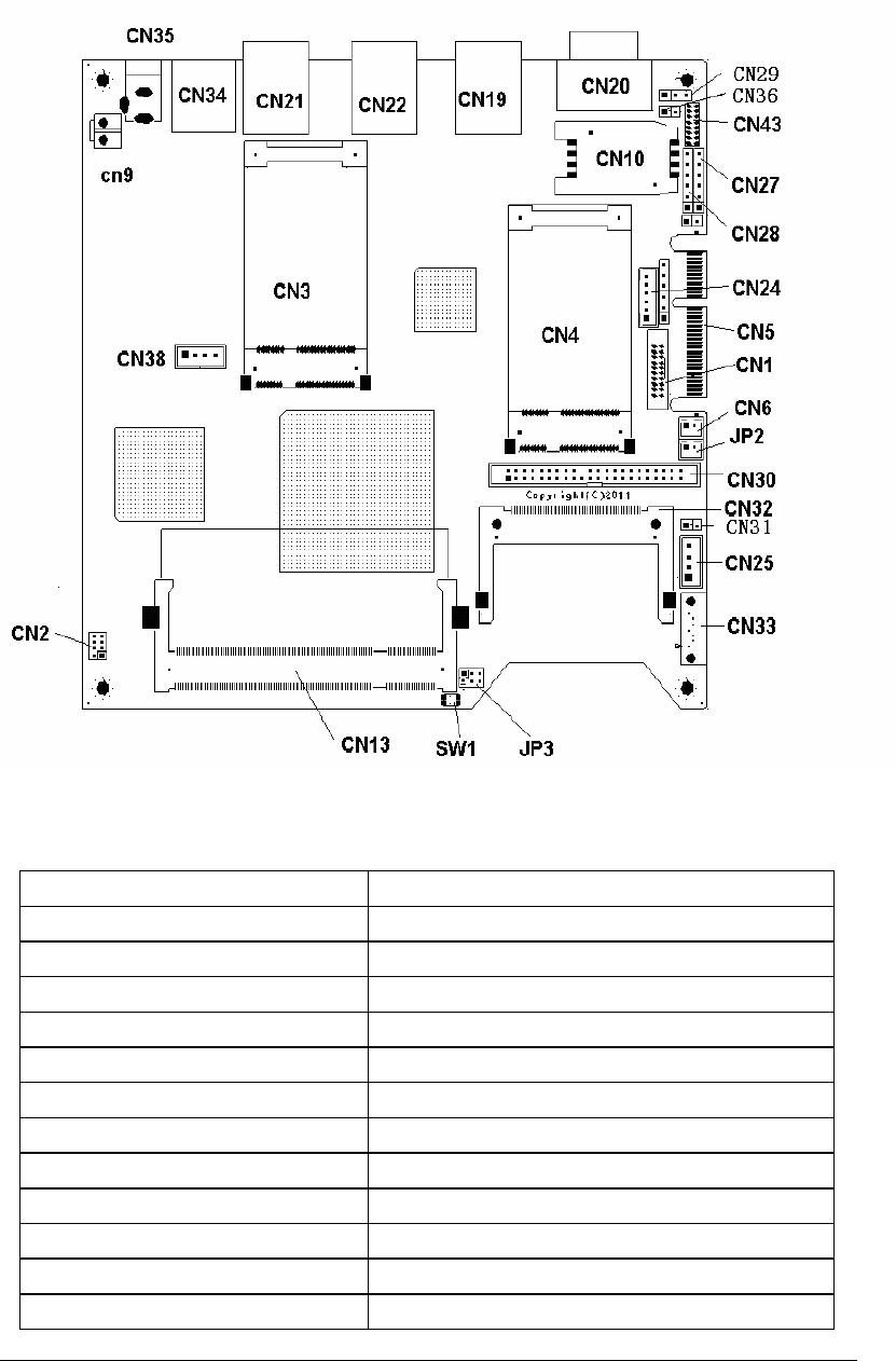
1. Layout
2. Connector and Jumper List
Name Function
CN1 SDVO display output
CN5 PCIe x4 Golden Finger
CN6 Clear CMOS
CN35 Main Power in Jacket
CN9 Power Supply Jacket
CN13 DDR2 Memory Slot
CN3 Mini PCIe Slot 1
CN4 Mini PCIe Slot 2
CN21 Ethernet 1
CN22 Ethernet 2
CN19 Ethernet 3
CN20 Serial Port

3/11
CN24 PS/2 Keyboard and Mouse Port
CN30 44 Pin IDE Interface
CN32 Compact Flash Interface
CN33 SATA Interface
CN25 SATA power supply
CN34 USB Port
CN43 LPC interface
JP2 Manual Reset In
JP3 IDE/SATA Configuration
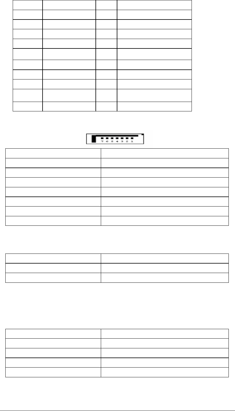
CN2 External LEDs and GPIO
CN38 USB connector
CN10 SIM Socket
CN27 POWER_LED Interface
CN28 HDD_LED Interface
CN29 Serial Port
CN36 12V Interface
CN31 12V Interface
SW1 GPI switch
System Status Indicator
Name Function
LED6 GPO use
LED17 GPO use
LED16 GPO use
SW1 GPI use
3. Connector and Jumper Description
CN1 SDVO Display Output ,SDVO (Serial Digital Video Out) is a proprietary Intel
technology introduced with their motherboard chipsets
Pin Name Pin Name
1 RED positive 2 Red negative
3 Ctrl Clk 4 Green positive
5 Green negative 6 Blue positive
7 Blue negative 8 CLK positive
9 CLK negative 10 Ctrl Data
11 Reset# 12 Gnd
13 Gnd 14 Gnd
15 3.3v 16 3.3v
17 3.3v 18 5v
19 5v 20 5v
4/11
CN6 clear CMOS
Setting Function
Close 1-2 Clear CMOS
Open 1-2 (default) Normal
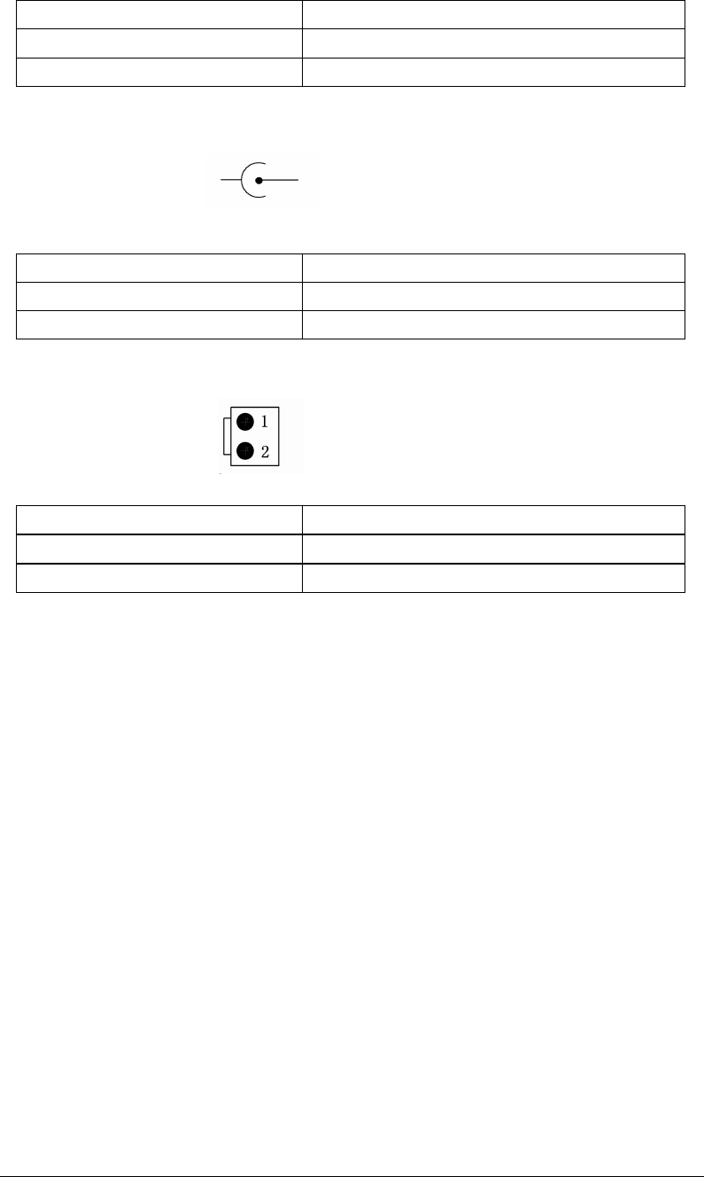
CN35 Main Power Jacket DC in @12V
1 2
Pin Name
1 Gnd
2 Vin
CN9 Power Supply Jacket DC out @12V
Pin Name
1 Vin
2 Gnd
CN13 DDR2 Memory Slot
1.8V
DDR2
Support for a maximum of 2GB of DRAM
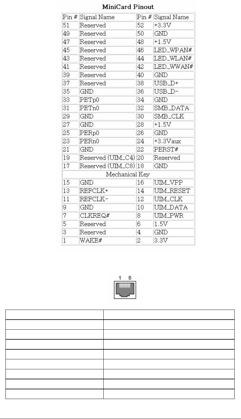
CN3 CN4 Mini PCIe Slot 1&2
Attach 3G SIM card to CN10, and attach MiniPCIe 3G module to CN3,
,,
,implement 3G
function for IPC110.
5/11
CN21/CN22/CN19 Giga Ethernet Port
Pin Name
1 BI_DA+
2 BI_DA-
3 BI_DB+
4 BI_DC+
5 BI_DC-
6 BI_DB-
7 BI_DD+
8 BI_DD-
6/11
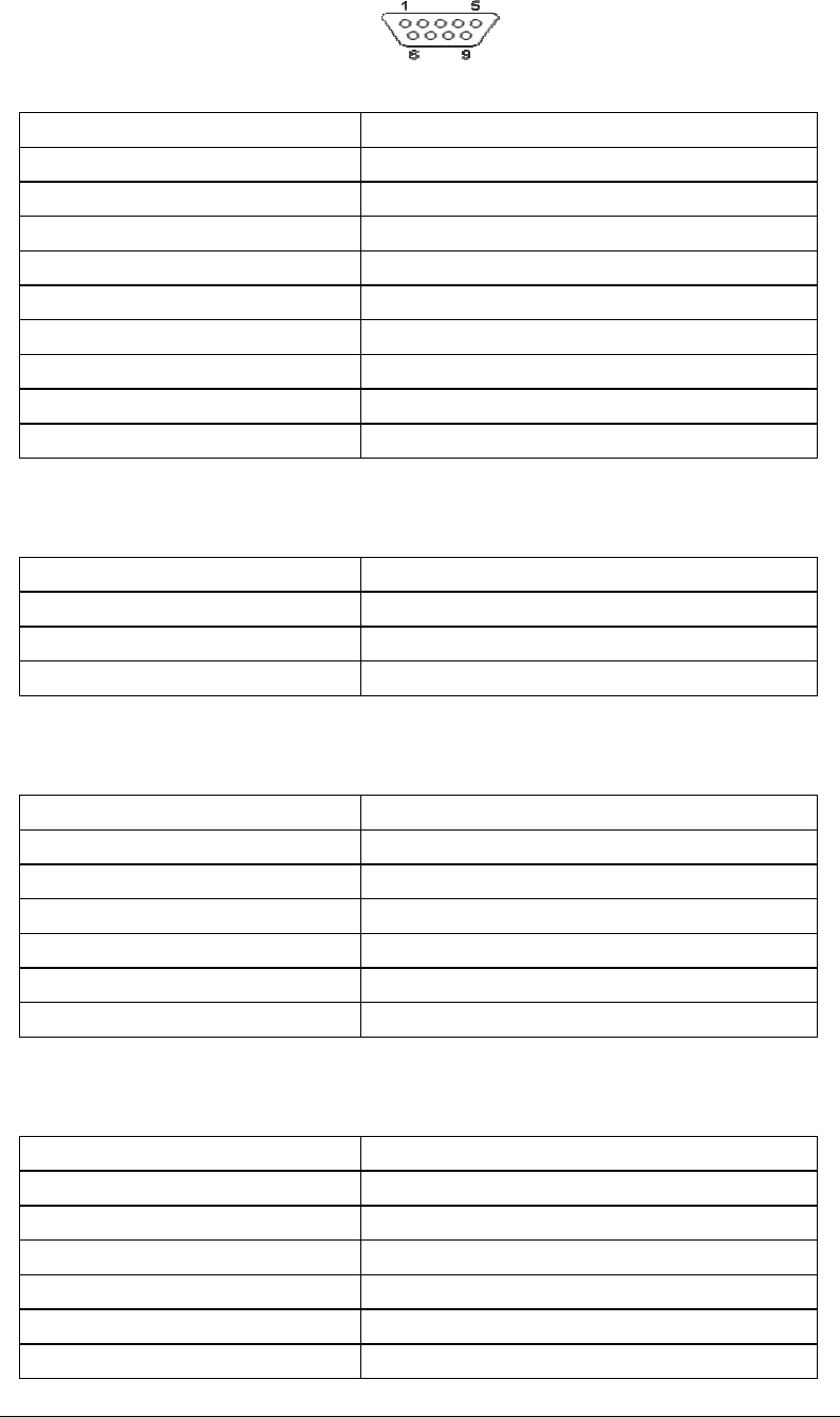
CN20 Serial R232 Port COM0 (DB9 male)
Pin Name
1 DCD
2 RXD
3 TXD
4 DTR
5 GND
6 DSR
7 RTS
8 CTS
9 RI
CN29 Serial R232 Port COM0
Pin Name
1 RX
2 TX
3 GND
CN24 PS2 Keyboard and Mouse Port
Pin Name
1 +5V
2 MSCLK
3 MSDATA
4 KBCLK
5 KBDATA
6 GND
CN27 POWER_LED Interface
Pin Name
1 PWR_LED_S3
2 GND
3 PWR_BTN
4 GND
5 PWR_LED
6 GND

7/11
CN28 HDD_LED Interface
Pin Name
1 IDE_LED_P
2 IDE_LED_N
3 CF_LED_P
4 CF_LED_N
5 SATA_LED_P
6 SATA_LED_N
CN30 44 Pin IDE Interface
44 pin (2.0mm pitch) for 2.5" harddisks.
Controller Drive 1 or 2 Drive 1 or 2
+--+ +--+ +--+
|::|===================|::|============|::| <-Pin 1
|::|===================|::|============|::|
|::|===================|::|============|::|
|::|===================|::|============|::|
|::|===================|::|============|::|
|::|===================|::|============|::|
|::|===================|::|============|::|
+--+ +--+ +--+

8/11
CN32 CompactFlash Interface
Pin Name Pin Name
1 GND 26 /CD1
2 D3 27 D11
3 D4 28 D12
4 D5 29 D13
5 D6 30 D14
6 D7 31 D15
7 /CE1 32 /CE2
8 A10 33 /VS1
9 /OE 34 /IORD
10 A9 35 /IOWR
11 A8 36 /WE
12 A7 37 /READY:/RDY:/IREQ
13 VCC 38 VCC
14 A6 39 CSEL
Pin
Name Pin Name
1 /RESET 23 /DIOW
2 GND 24 GND
3 DD7 25 /DIOR
4 DD8 26 GND
5 DD6 27 IORDY
6 DD9 28 SPSYNC:CSEL
7 DD5 29 /DMACK
8 DD10 30 GND
9 DD4 31 INTRQ
10
DD11 32 /IOCS16
11
DD3 33 DA1
12
DD12 34 PDIAG
13
DD2 35 DA0
14
DD13 36 DA2
15
DD1 37 /IDE_CS0
16
DD14 38 /IDE_CS1
17
DD0 39 /ACTIVE
18
DD15 40 GND
19
GND 41 +5V
20
KEY 42 +5V
21 DMARQ 43 GND
22 GND 44 GND
9/11
15 A5 40 /VS2
16 A4 41 RESET
17 A3 42 /WAIT
18 A2 43 /INPACK
19 A1 44 /REG
20 A0 45 /BVD2:SPKR
21 D0 46 /BVD1:STSCHG
22 D1 47 D8
23 D2 48 D9
24 /WP:/IOIS16 49 D10
25 /CD2 50 GND
CN33 SATA Interface
Pin Name
1 Ground
2 Transmit +
3 Transmit -
4 Ground
5 Receive -
6 Receive +
7 Ground
CN31
11
1/
//
/CN36 12V output Interface
Pin Name
1 12V
2 Ground
CN25 SATA Power Supply
Pin Name
1 5v
2 Ground
3 Ground
4 12v
10/11
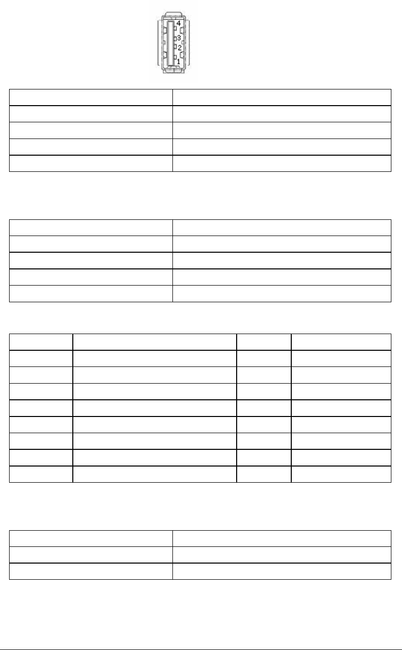
CN34 USB Port
2 USB2.0 ports .
500 mA Continuous Current per Channel. Short-Circuit and Thermal
Protection With Overcurrent Logic.
Pin Name
1 5v
2 Data-
3 Data+
4 Ground
CN38 USB connector
Pin Name
1 5v
2 Data-
3 Data+
4 Ground
CN43 LPC Interface
Pin Name Pin Name
1 LPC_CLK 9 AD3
2 SERIRQ 10 +3.3V
3 AD0 11 FRAME#
4 NC 12 GND
5 AD1 13 GND
6 GND 14 NC
7 AD2 15 48MHz_CLK
8 +5V 16 NC
JP2 Manual Reset In
Setting Function
Close 1-2 Reset System
Open 1-2 (default) Normal

11/11
JP3 IDE/SATA Configuration
2*4*2.0mm header
Default Setting Function
Open 1-2 CF Slave (close it means CF master)
Close 3-4 IDE Master (open it means IDE slave)
Close 5-6 Disable SATA (default)
Note:1. There's a important principle that only one device can be allowed to exsit in one
master (slave) simultaneously. IDE device Should be a SATA hard disk drive ,a type II CF
card, or a IDE hard disk drive.
2. You should disable SATA (close 5-6) first before attach CF card or IDE hard disk ,..
If not ,system will spend more time to detect IDE devices. That means Pin 5-6 are only
open at the case when user using SATA hard disk.
FCC STATEMENT
1. This device complies with Part 15 of the FCC Rules. Operation is subject to the following two
conditions:
(1) This device may not cause harmful interference.
(2) This device must accept any interference received, including interference that may cause
undesired operation.
2. Changes or modifications not expressly approved by the party responsible for compliance could
void the user's authority to operate the equipment.
NOTE: This equipment has been tested and found to comply with the limits for a Class B digital
device, pursuant to Part 15 of the FCC Rules. These limits are designed to provide reasonable
protection against harmful interference in a residential installation.
This equipment generates uses and can radiate radio frequency energy and, if not installed and
used in accordance with the instructions, may cause harmful interference to radio communications.
However, there is no guarantee that interference will not occur in a particular installation. If this
equipment does cause harmful interference to radio or television reception, which can be
determined by turning the equipment off and on, the user is encouraged to try to correct the
interference by one or more of the following measures:
Reorient or relocate the receiving antenna.
Increase the separation between the equipment and receiver.
Connect the equipment into an outlet on a circuit different from that to which the receiver is
connected.
Consult the dealer or an experienced radio/TV technician for help.