Panasonic Devices Europe 1316 Bluetooth Module User Manual TABLE OF CONTENTS
Panasonic Industrial Devices Europe GmbH Bluetooth Module TABLE OF CONTENTS
UserManual.wiki
>
Panasonic Devices Europe
>
1316 User Manual
15_PAN1316 UserMan
Navigation menu
Upload a User Manual
Namespaces
Wiki Guide
HTML
PDF
Info
Views
User Manual
Discussion / Help
Navigation
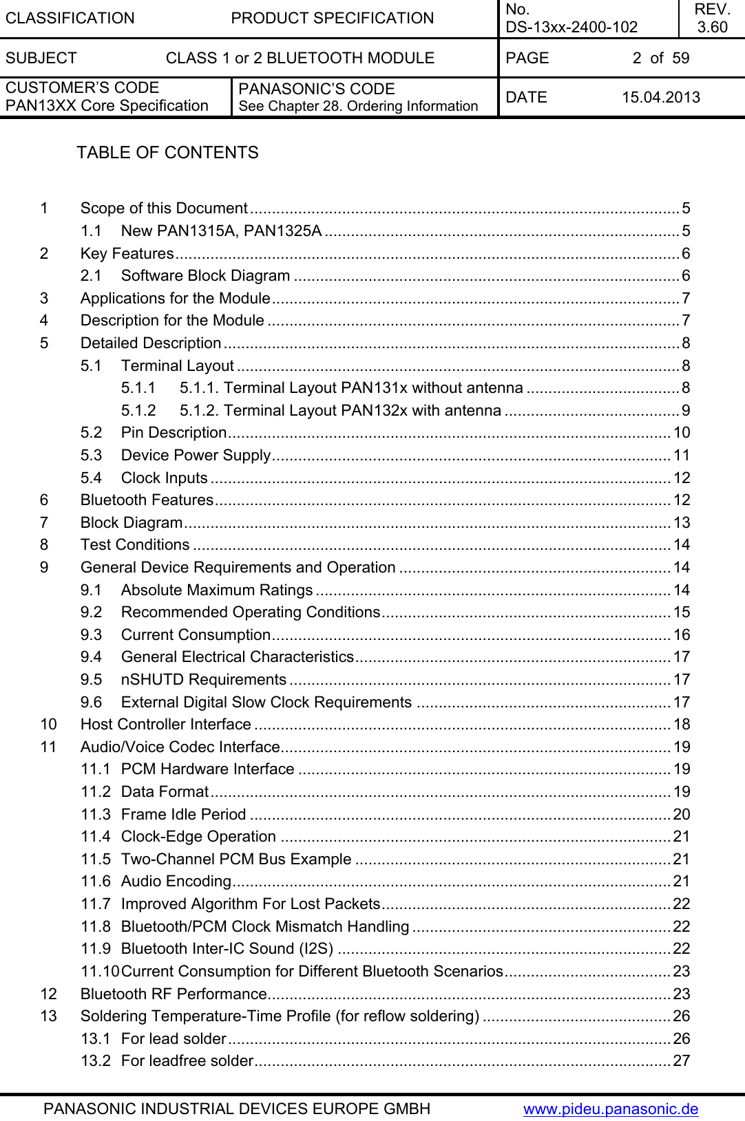
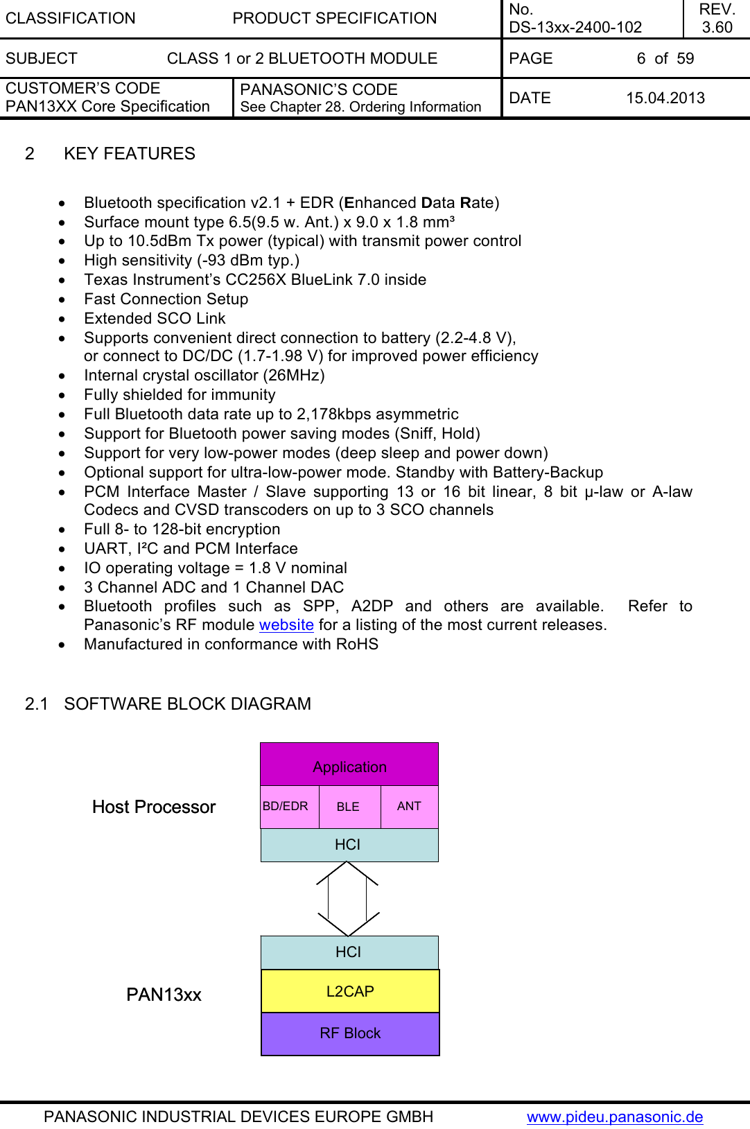
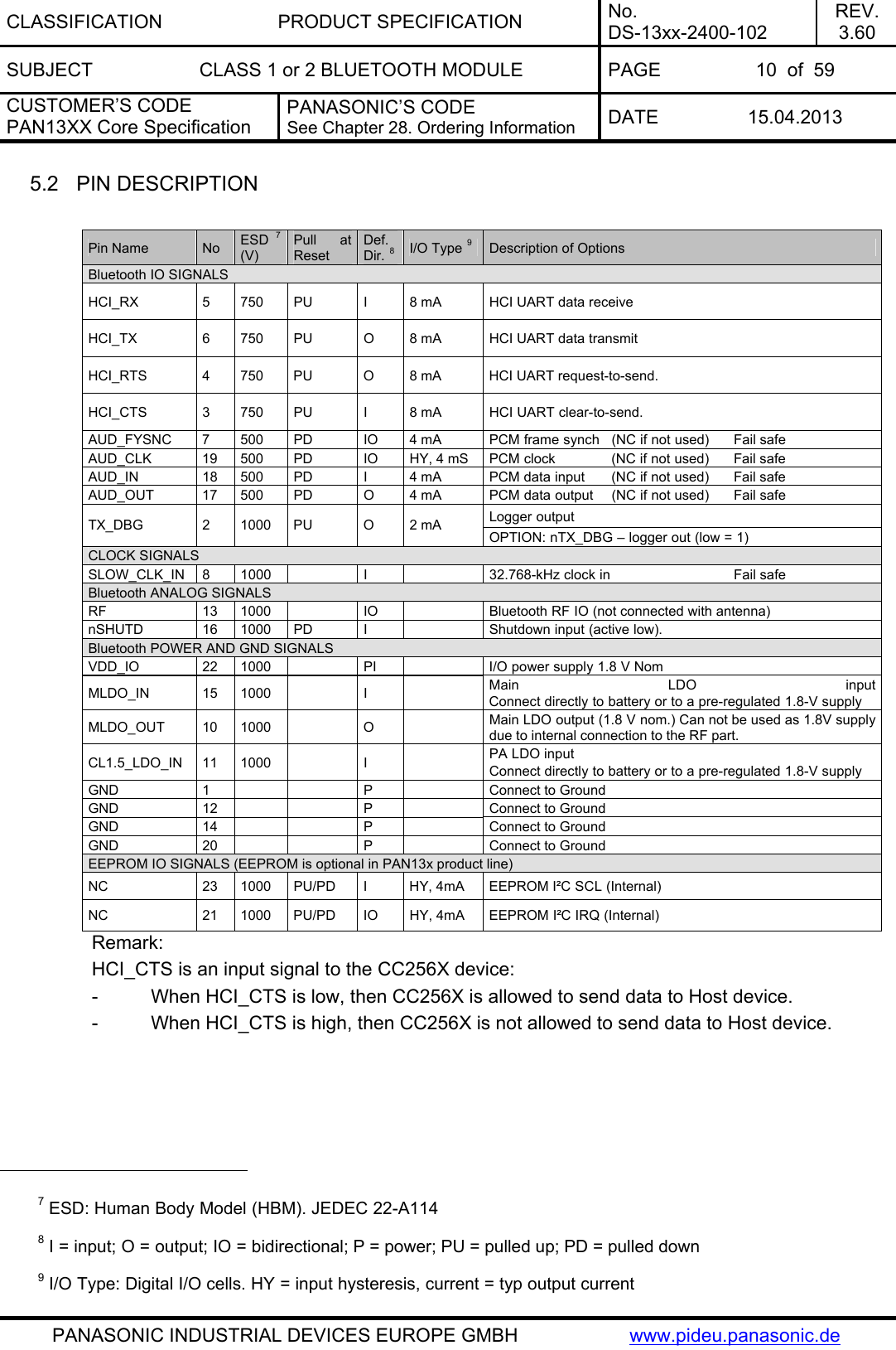
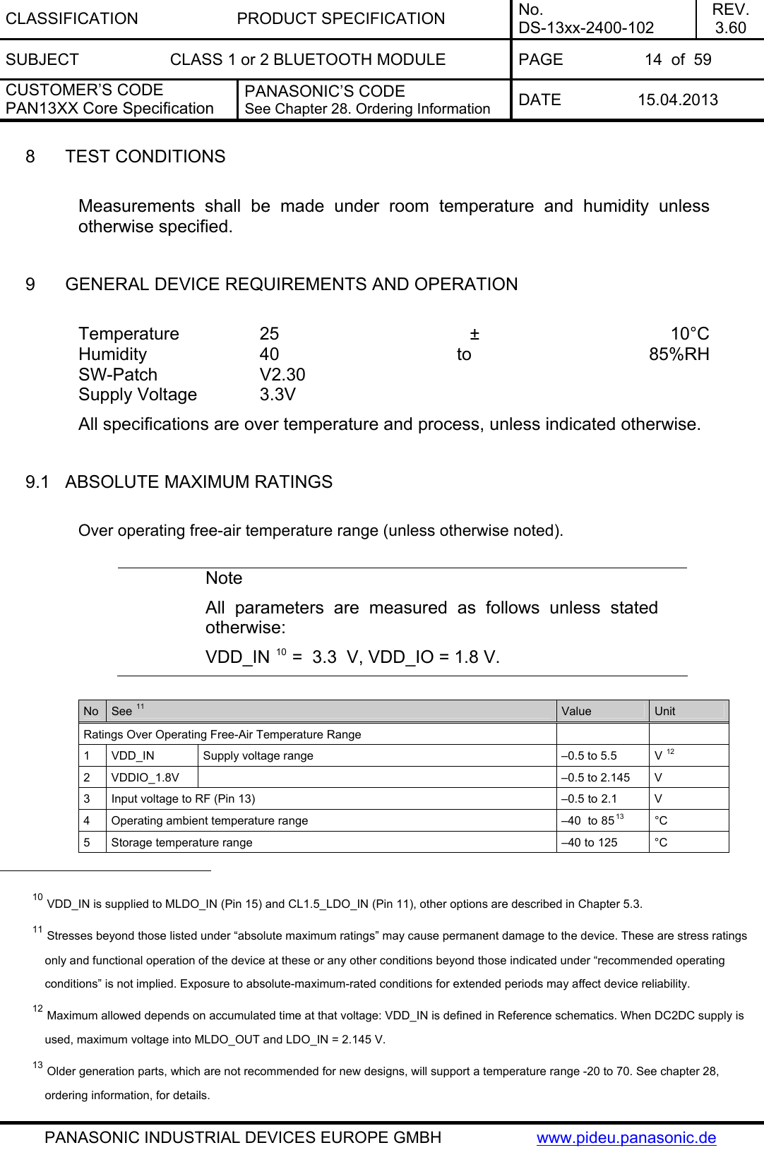
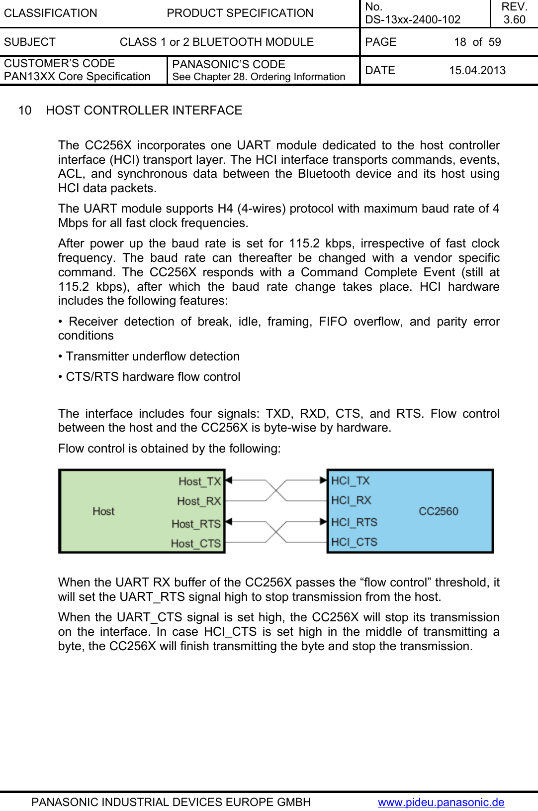
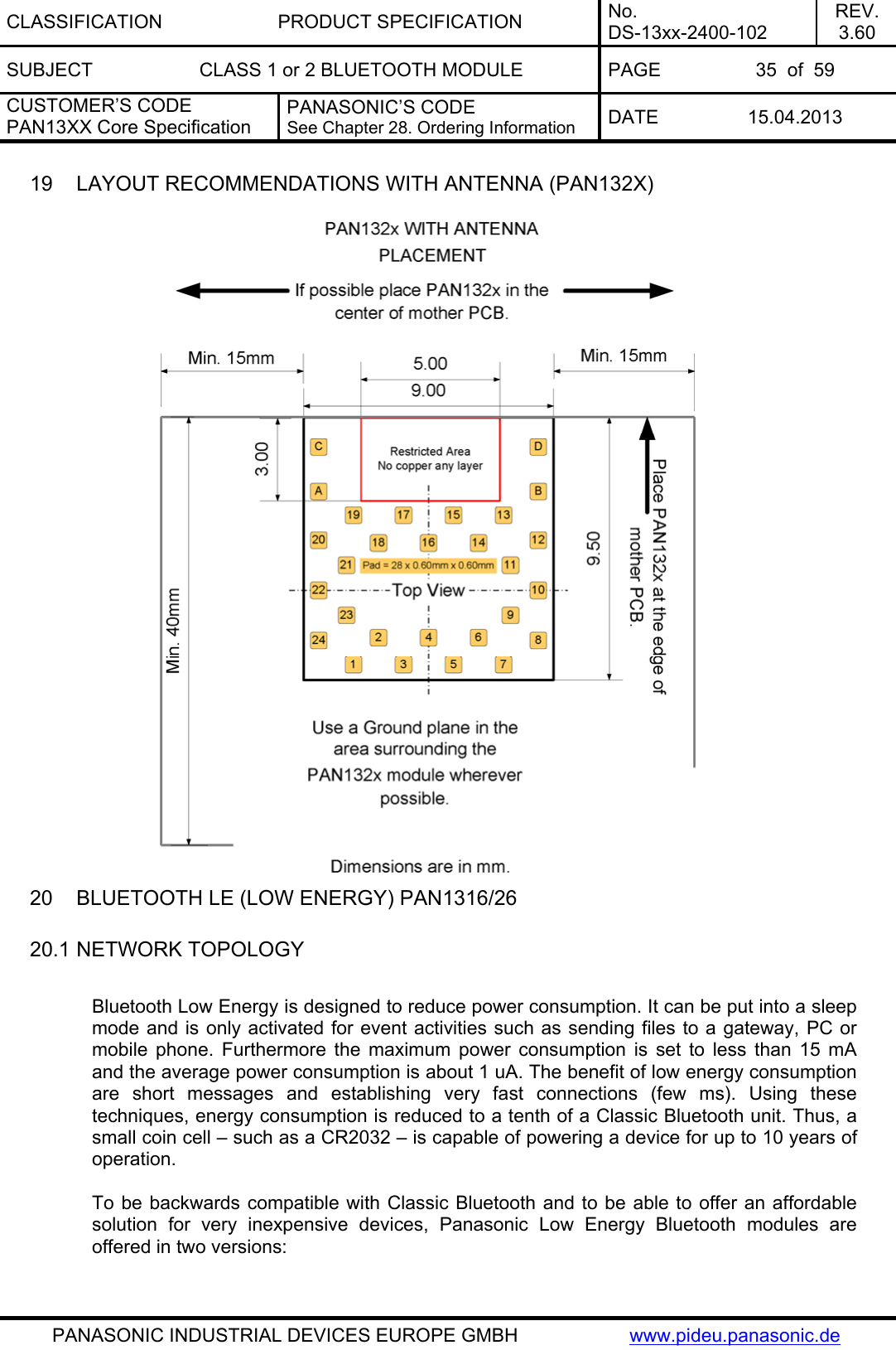
![CLASSIFICATION PRODUCT SPECIFICATION No. DS-13xx-2400-102 REV. 3.60 SUBJECT CLASS 1 or 2 BLUETOOTH MODULE PAGE 23 of 59 CUSTOMER’S CODE PAN13XX Core Specification PANASONIC’S CODE See Chapter 28. Ordering Information DATE 15.04.2013 PANASONIC INDUSTRIAL DEVICES EUROPE GMBH www.pideu.panasonic.de 11.10 CURRENT CONSUMPTION FOR DIFFERENT BLUETOOTH SCENARIOS The following table gives average current consumption for different Bluetooth scenarios. Conditions: VDD_IN = 3.6 V, 25°C, 26-MHz fast clock, nominal unit, 4 dBm output power. 12 BLUETOOTH RF PERFORMANCE No Characteristics Typ BT Spec Max BT Spec Min Class1 Class1 1 Average Power Hopping DH5 [dBm] 22, 23 7.2 20 4 2 Average Power: Ch0 [dBm] 22, 23 7.5 20 4 3 Peak Power: Ch0 [dBm] 22, 23 7.7 23 4 Average Power: Ch39 [dBm] 22, 23 7.0 20 4 5 Peak Power: Ch39 [dBm] 22, 23 7.2 23 6 Average Power: Ch78 [dBm] 22, 23 6.7 20 4 7 Peak Power: Ch78 [dBm] 22, 23 7.0 23 8 Max. Frequency Tolerance: Ch0 [kHz] -2.6 75 -75 9 Max. Frequency Tolerance: Ch39 [kHz] -2.2 75 -75 10 Max. Frequency Tolerance: Ch78 [kHz] -2.1 75 -75 11 Max. Drift: Ch0_DH1 [kHz] 3.6 25 -25 12 Max. Drift: Ch0_DH3 [kHz] 3.7 40 -40 13 Max. Drift: Ch0_DH5 [kHz] 4.0 40 -40 14 Max. Drift Rate: Ch0_DH1 [kHz] -2.6 20 -20 15 Max. Drift Rate: Ch0_DH3 [kHz] -3.2 20 -20 16 Max. Drift Rate: Ch0_DH5 [kHz] -3.3 20 -20 17 Max. Drift: Ch39_DH1 [kHz] 4.0 25 -25 18 Max. Drift: Ch39_DH3 [kHz] 4.3 40 -40 19 Max. Drift: Ch39_DH5 [kHz] 4.3 40 -40 20 Max. Drift Rate: Ch39_DH1 [kHz] -3.1 20 -20 21 Max. Drift Rate: Ch39_DH3 [kHz] -3.6 20 -20 22 Max. Drift Rate: Ch39_DH5 [kHz] -3.7 20 -20](https://usermanual.wiki/Panasonic-Devices-Europe/1316/User-Guide-1945225-Page-23.png)
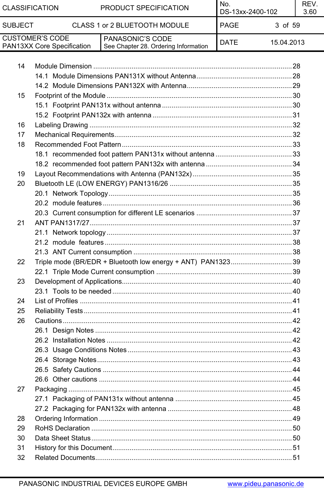
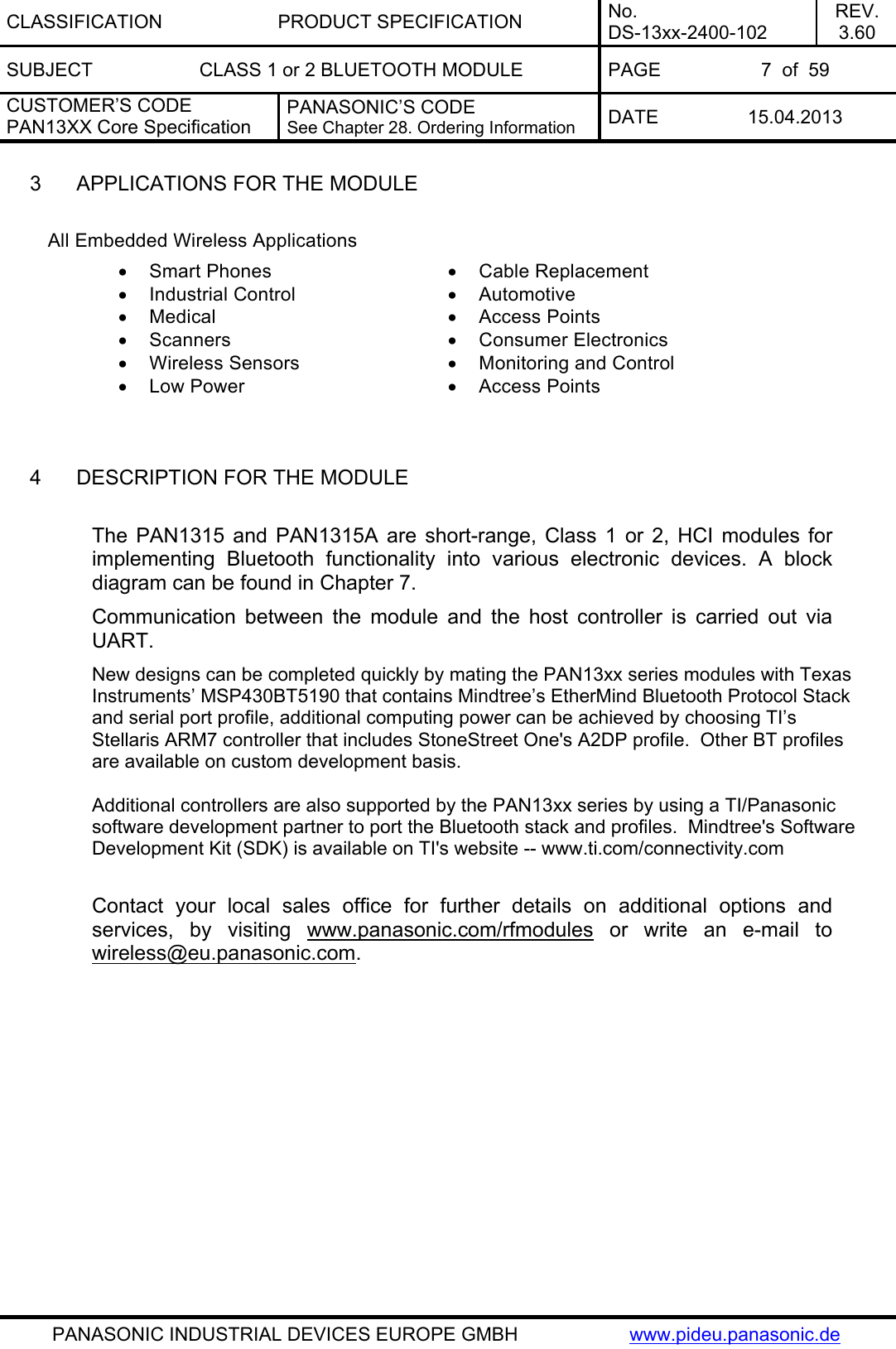
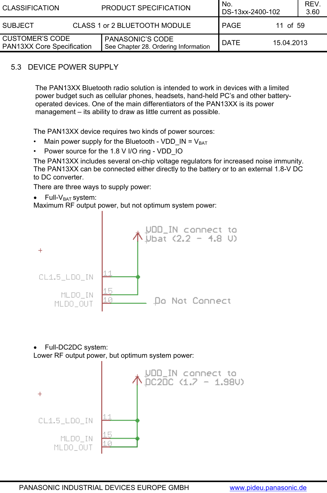
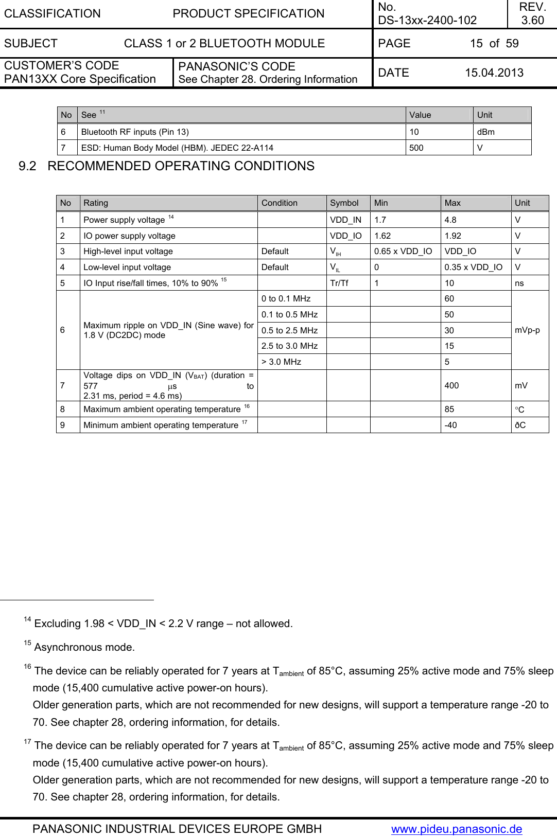
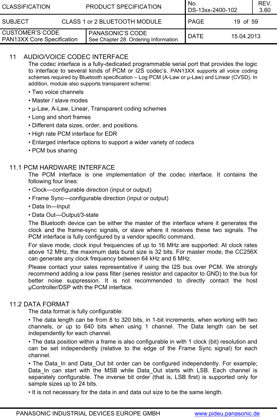
![CLASSIFICATION PRODUCT SPECIFICATION No. DS-13xx-2400-102 REV. 3.60 SUBJECT CLASS 1 or 2 BLUETOOTH MODULE PAGE 24 of 59 CUSTOMER’S CODE PAN13XX Core Specification PANASONIC’S CODE See Chapter 28. Ordering Information DATE 15.04.2013 PANASONIC INDUSTRIAL DEVICES EUROPE GMBH www.pideu.panasonic.de No Characteristics Typ BT Spec Max BT Spec Min Class1 Class1 23 Max. Drift: Ch78_DH1 [kHz] 4.1 25 -25 24 Max. Drift: Ch78_DH3 [kHz] 4.5 40 -40 25 Max. Drift: Ch78_DH5 [kHz] 4.4 40 -40 26 Max. Drift Rate: Ch78_DH1 [kHz] -3.4 20 -20 27 Max. Drift Rate: Ch78_DH3 [kHz] -3.9 20 -20 28 Max. Drift Rate: Ch78_DH5 [kHz] -4.1 20 -20 29 Delta F1 Avg: Ch0 [kHz] 159.5 175 140 30 Delta F2 Max.: Ch0 [%] 100.0 99.9 31 Delta F2 Avg/Delta F1 Avg: Ch0 0.9 0.8 32 Delta F1 Avg: Ch39 [kHz] 159.8 175 140 33 Delta F2 Max.: Ch39 [%] 100.0 99.9 34 Delta F2 Avg/Delta F1 Avg: Ch39 0.9 0.8 35 Delta F1 Avg: Ch78 [kHz] 159.1 175 140 36 Delta F2 Max.: Ch78 [%] 100.0 99.9 37 Delta F2 Avg/Delta F1 Avg: Ch78 0.9 0.8 45 Sensitivity -93.0 -81 46 f(H)-f(L): Ch0 [kHz] 918.4 1000 47 f(H)-f(L): Ch39 [kHz] 918.3 1000 48 f(H)-f(L): Ch78 [kHz] 918.2 1000 49 ACPower -3: Ch3 [dBm] -51.5 -40 50 ACPower -2: Ch3 [dBm] -50.4 -40 51 ACPower -1: Ch3 [dBm] -18.5 52 ACPower Center: Ch3 [dBm] 8.1 20 4 53 ACPower +1: Ch3 [dBm] -19.2 54 ACPower +2: Ch3 [dBm] -50.7 -40 55 ACPower +3: Ch3 [dBm] -53.3 -40 56 ACPower -3: Ch39 [dBm] -51.6 -40 57 ACPower -2: Ch39 [dBm] -50.7 -40 58 ACPower -1: Ch39 [dBm] -19.0 59 ACPower Center: Ch39 [dBm] 7.7 20 4 60 ACPower +1: Ch39 [dBm] -19.7 61 ACPower +2: Ch39 [dBm] -50.9 -40 62 ACPower +3: Ch39 [dBm] -53.2 -40 63 ACPower -3: Ch75 [dBm] -51.7 -40 64 ACPower -2: Ch75 [dBm] -50.7 -40 65 ACPower -1: Ch75 [dBm] -19.2 66 ACPower Center: Ch75 [dBm] 7.5 20 4 67 ACPower +1: Ch75 [dBm] -20.0 68 ACPower +2: Ch75 [dBm] -51.0 -40 69 ACPower +3: Ch75 [dBm] -53.4 -40 70 omega i 2-DH5: Ch0 [kHz] -4.7 75 -75 71 omega o + omega i 2-DH5: Ch0 [kHz] -6.0 75 -75 72 omega o 2-DH5: Ch0 [kHz] -1.5 10 -10 73 DEVM RMS 2-DH5: Ch0 [%] 0.0 0.2 74 DEVM Peak 2-DH5: Ch0 [%] 0.1 0.35](https://usermanual.wiki/Panasonic-Devices-Europe/1316/User-Guide-1945225-Page-24.png)
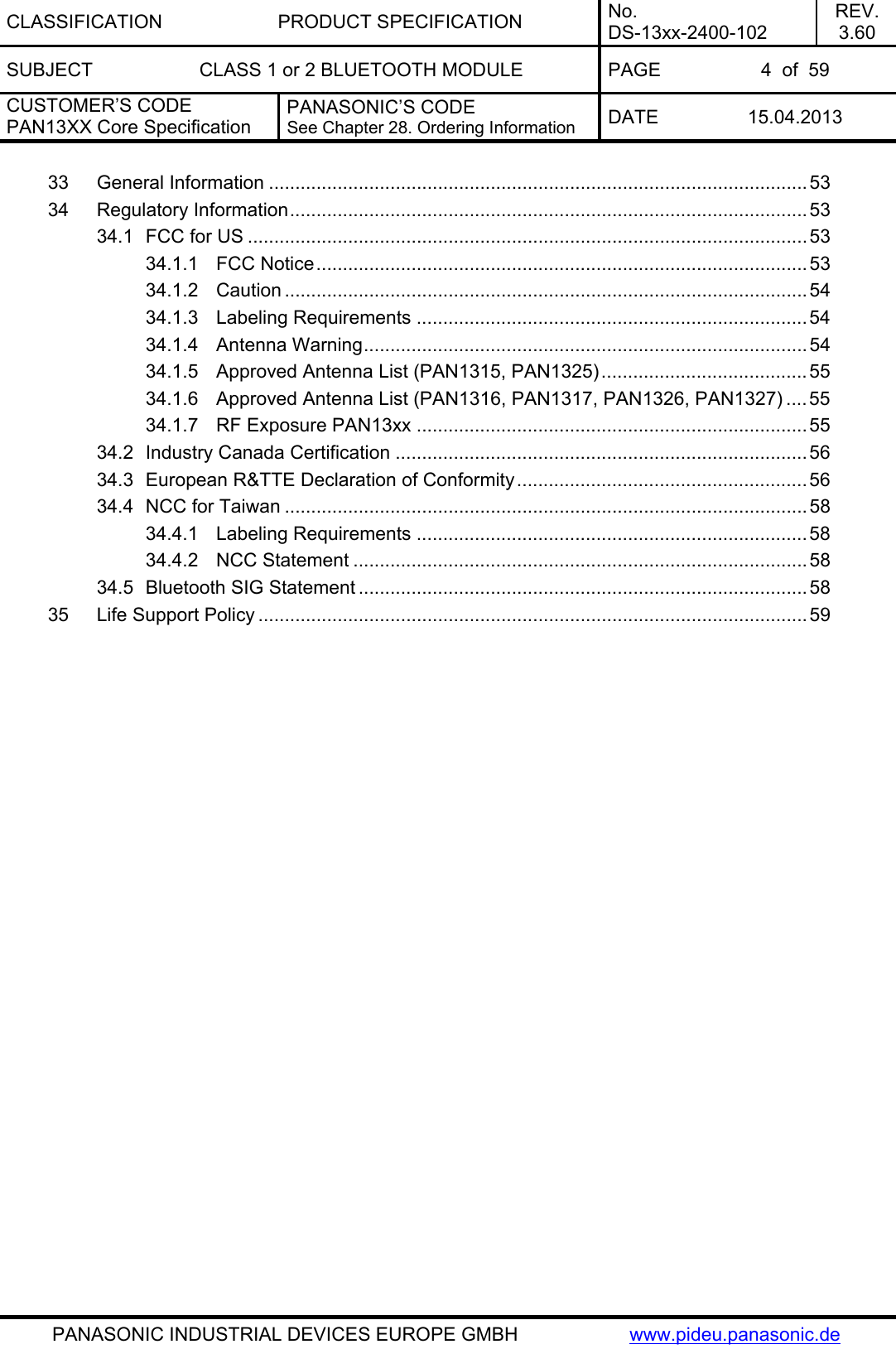
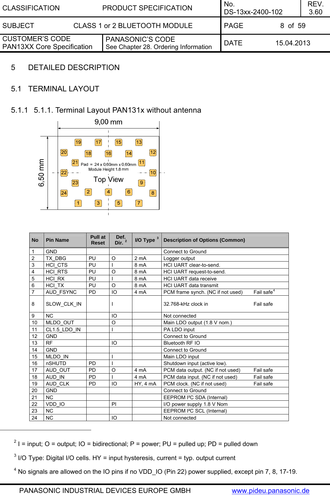
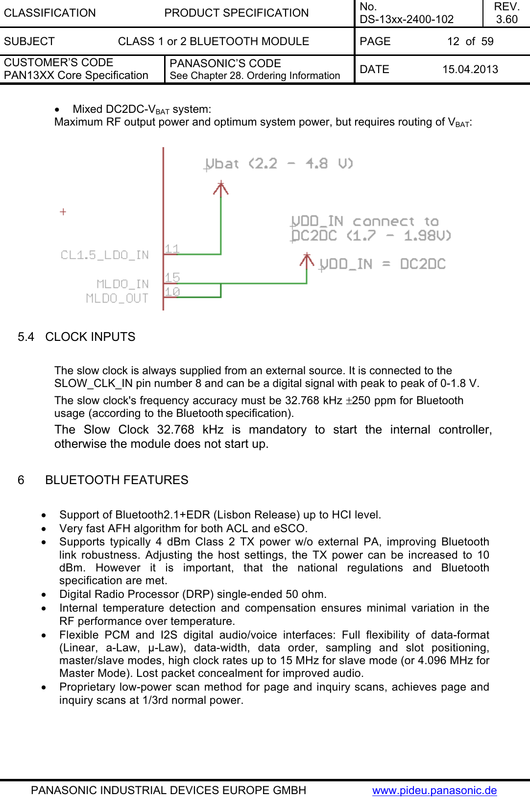
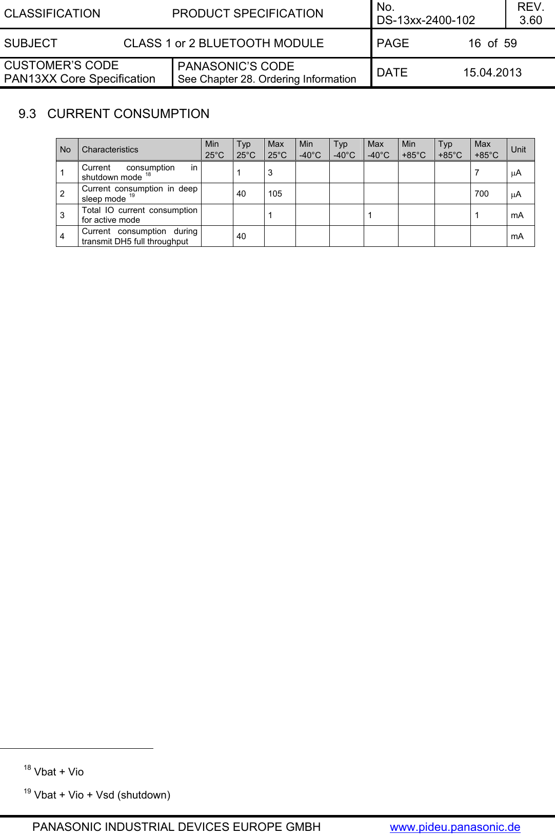
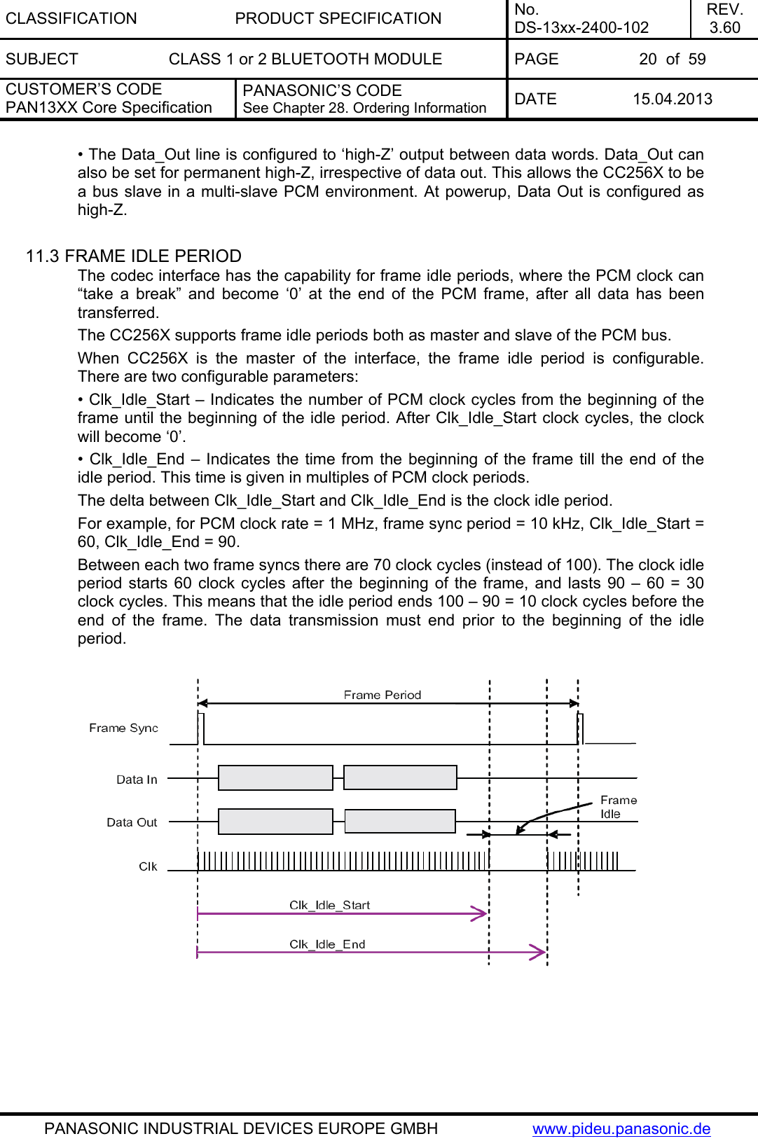
![CLASSIFICATION PRODUCT SPECIFICATION No. DS-13xx-2400-102 REV. 3.60 SUBJECT CLASS 1 or 2 BLUETOOTH MODULE PAGE 25 of 59 CUSTOMER’S CODE PAN13XX Core Specification PANASONIC’S CODE See Chapter 28. Ordering Information DATE 15.04.2013 PANASONIC INDUSTRIAL DEVICES EUROPE GMBH www.pideu.panasonic.de No Characteristics Typ BT Spec Max BT Spec Min Class1 Class1 75 DEVM 99% 2-DH5: Ch0 [%] 100.0 99 76 omega i 3-DH5: Ch0 [kHz] -3.7 75 -75 77 omega o + omega i 3-DH5: Ch0 [kHz] -5.8 75 -75 78 omega o 3-DH5: Ch0 [kHz] -2.6 10 -10 79 DEVM RMS 3-DH5: Ch0 [%] 0.0 0.13 80 DEVM Peak 3-DH5: Ch0 [%] 0.1 0.25 81 DEVM 99% 3-DH5: Ch0 [%] 100.0 99 82 omega i 2-DH5: Ch39 [kHz] -4.8 75 -75 83 omega o + omega i 2-DH5: Ch39 [kHz] -6.1 75 -75 84 omega o 2-DH5: Ch39 [kHz] -1.4 10 -10 85 DEVM RMS 2-DH5: Ch39 [%] 0.0 0.2 86 DEVM Peak 2-DH5: Ch39 [%] 0.1 0.35 87 DEVM 99% 2-DH5: Ch39 [%] 100.0 99 88 omega i 3-DH5: Ch39 [kHz] -3.8 75 -75 89 omega o + omega i 3-DH5: Ch39 [kHz] -5.9 75 -75 90 omega o 3-DH5: Ch39 [kHz] -2.6 10 -10 91 DEVM RMS 3-DH5: Ch39 [%] 0.0 0.13 92 DEVM Peak 3-DH5: Ch39 [%] 0.1 0.25 93 DEVM 99% 3-DH5: Ch39 [%] 100.0 99 94 omega i 2-DH5: Ch78 [kHz] -4.9 75 -75 95 omega o + omega i 2-DH5: Ch78 [kHz] -6.2 75 -75 96 omega o 2-DH5: Ch78 [kHz] -1.4 10 -10 97 DEVM RMS 2-DH5: Ch78 [%] 0.0 0.2 98 DEVM Peak 2-DH5: Ch78 [%] 0.1 0.35 99 DEVM 99% 2-DH5: Ch78 [%] 100.0 99 100 omega i 3-DH5: Ch78 [kHz] -3.8 75 -75 101 omega o + omega i 3-DH5: Ch78 [kHz] -6.0 75 -75 102 omega o 3-DH5: Ch78 [kHz] -2.7 10 -10 103 DEVM RMS 3-DH5: Ch78 [%] 0.0 0.13 104 DEVM Peak 3-DH5: Ch78 [%] 0.1 0.25 105 DEVM 99% 3-DH5: Ch78 [%] 100.0 99 No Characteristics Condition Min Typ Max BT Spec Unit 1 Operation frequency range 2402 2480 MHz 2 Channel spacing 1 MHz 3 Input impedance 50 Ω GFSK, BER = 0.1% -93.0 -70 Pi/4-DQPSK, BER = 0.01% -92.5 -70 4 Sensitivity, Dirty Tx on 8DPSK, BER = 0.01% -85.5 -70 dBm](https://usermanual.wiki/Panasonic-Devices-Europe/1316/User-Guide-1945225-Page-25.png)
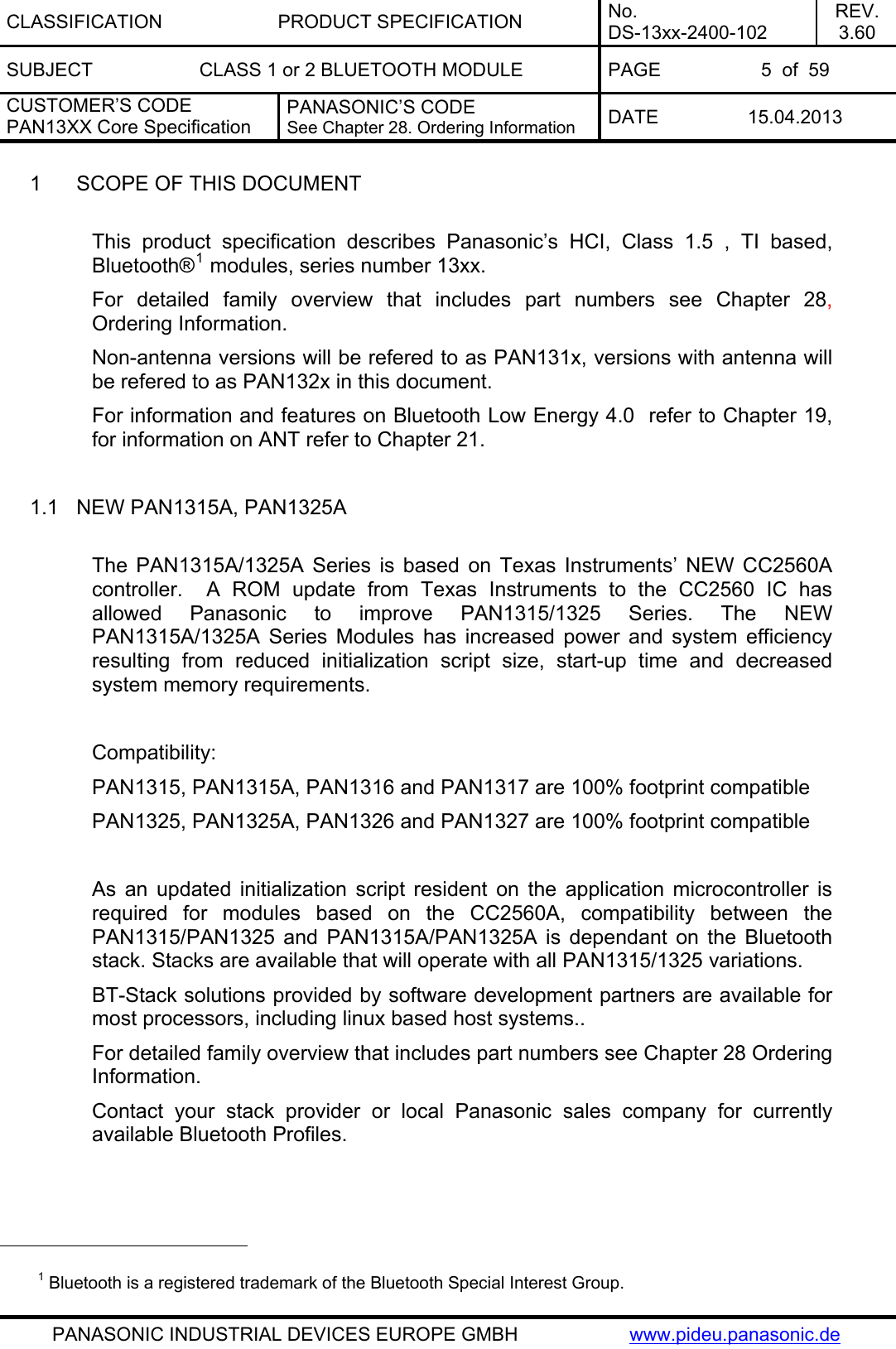
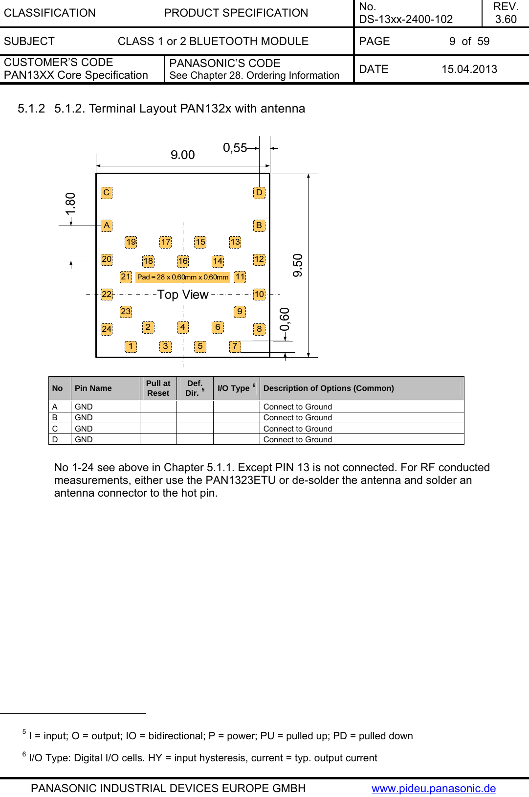
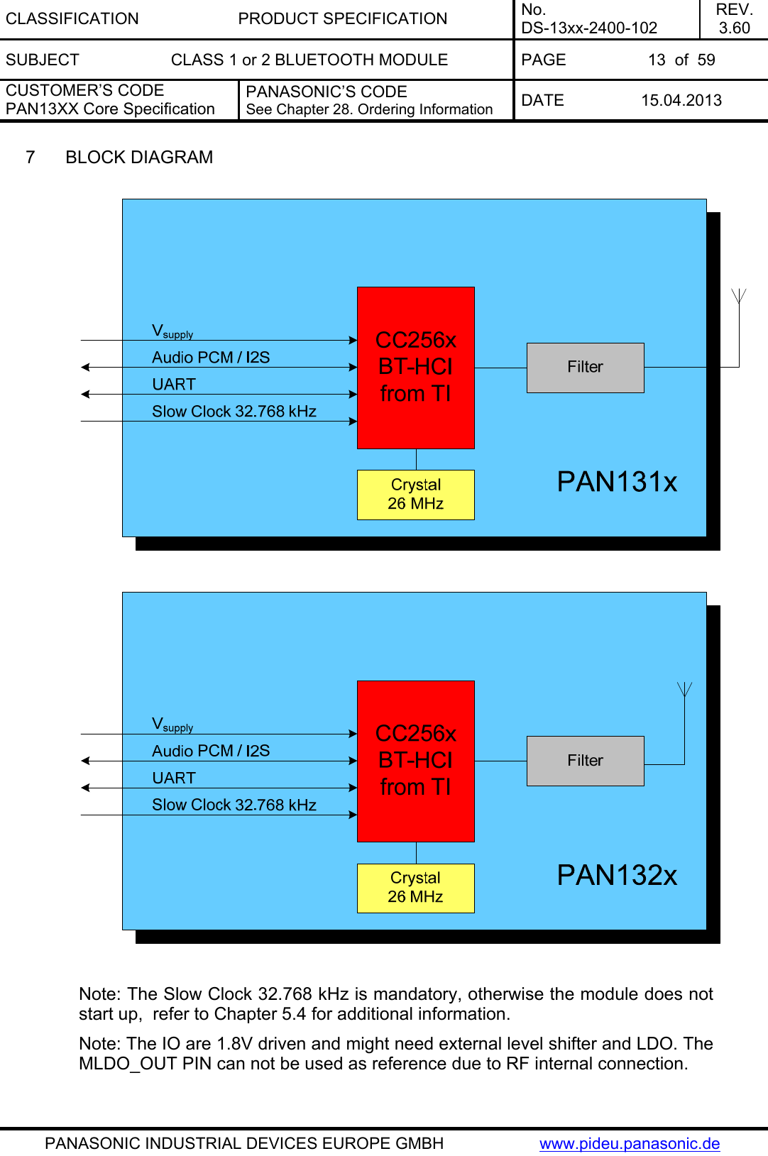
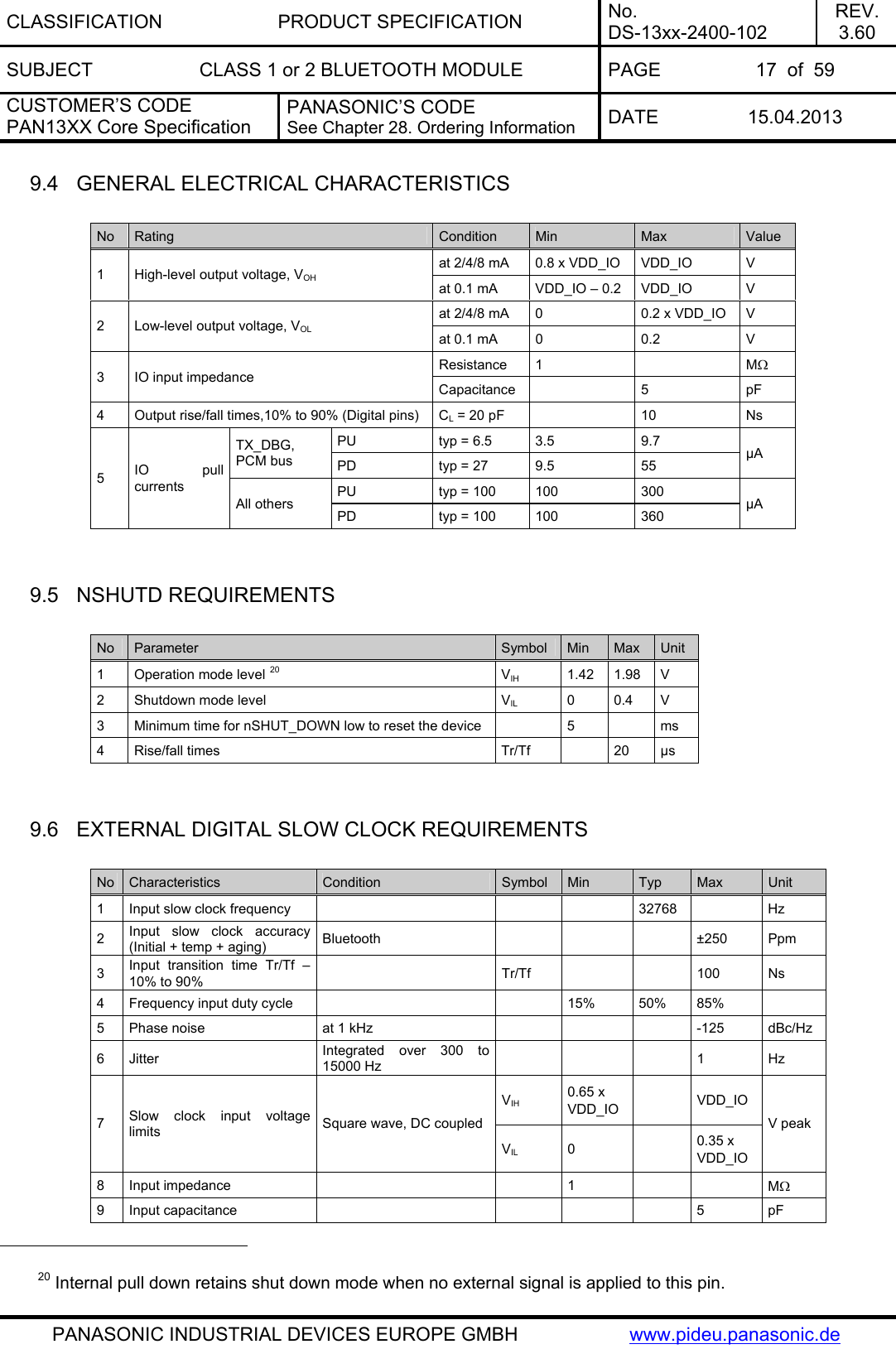
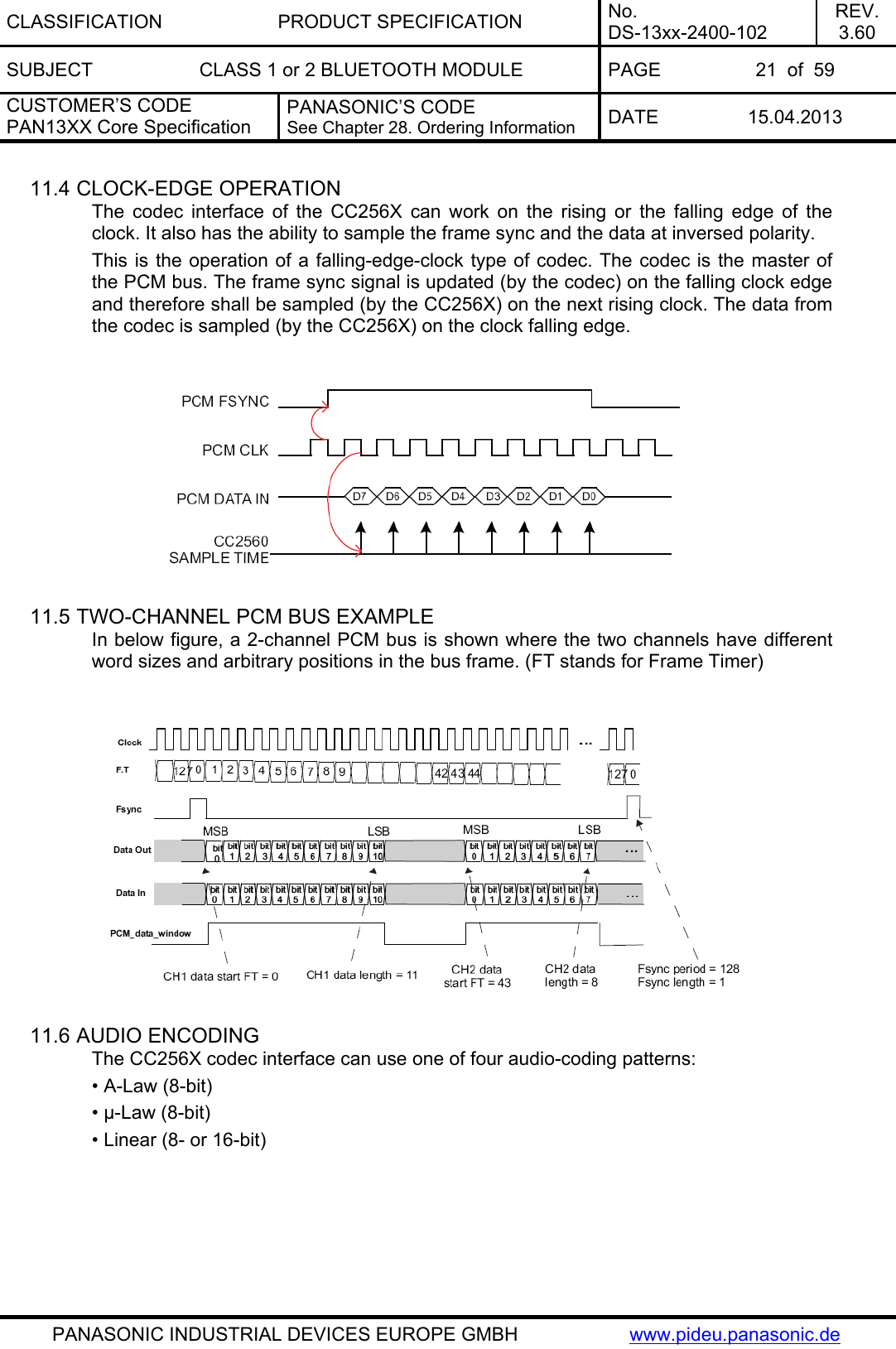
![CLASSIFICATION PRODUCT SPECIFICATION No. DS-13xx-2400-102 REV. 3.60 SUBJECT CLASS 1 or 2 BLUETOOTH MODULE PAGE 26 of 59 CUSTOMER’S CODE PAN13XX Core Specification PANASONIC’S CODE See Chapter 28. Ordering Information DATE 15.04.2013 PANASONIC INDUSTRIAL DEVICES EUROPE GMBH www.pideu.panasonic.de No Characteristics Condition Typ Max Unit 30 kHz to 1 GHz 21 , 22, 23 -30 1 Tx and Rx out-of-band emissions Output signal = 7dBm 1 to 12.75 GHz 21, 22, 23 -30 dBm 2 2nd harmonic at 7dBm output power 21, 22, 23 -30 dBm 3 3rd harmonic at 7dBm output power 21, 22, 23 -30 dBm The values are measured conducted. Better suppression of the spurious emissions with an antenna can be expected as, antenna frequently have band pass filter characteristics. 13 SOLDERING TEMPERATURE-TIME PROFILE (FOR REFLOW SOLDERING) 13.1 FOR LEAD SOLDER Recommended temp. profile for reflow soldering Temp.[°C] Time [s] 235°C max. 220 ±5°C 200°C150 ±10°C 90 ±30s 10 ±1s 30 +20/-10s 21 Includes effects of frequency hopping 22 Average according FCC, IC and ETSI requirements. Above +7dBm output power (refer also to 23) the customer has to verify the final product against national regulations. 23 +7dBm related to power register value 18, according to TI service pack 2.30](https://usermanual.wiki/Panasonic-Devices-Europe/1316/User-Guide-1945225-Page-26.png)
![CLASSIFICATION PRODUCT SPECIFICATION No. DS-13xx-2400-102 REV. 3.60 SUBJECT CLASS 1 or 2 BLUETOOTH MODULE PAGE 27 of 59 CUSTOMER’S CODE PAN13XX Core Specification PANASONIC’S CODE See Chapter 28. Ordering Information DATE 15.04.2013 PANASONIC INDUSTRIAL DEVICES EUROPE GMBH www.pideu.panasonic.de 13.2 FOR LEADFREE SOLDER Our used temp. profile for reflow soldering Temp.[°C] Time [s] 230°C -250°C max. 220°C150°C – 190°C 90 ±30s 30 +20/-10s Reflow permissible cycle: 2 Opposite side reflow is prohibited due to module weight.](https://usermanual.wiki/Panasonic-Devices-Europe/1316/User-Guide-1945225-Page-27.png)
![CLASSIFICATION PRODUCT SPECIFICATION No. DS-13xx-2400-102 REV. 3.60 SUBJECT CLASS 1 or 2 BLUETOOTH MODULE PAGE 47 of 59 CUSTOMER’S CODE PAN13XX Core Specification PANASONIC’S CODE See Chapter 28. Ordering Information DATE 15.04.2013 PANASONIC INDUSTRIAL DEVICES EUROPE GMBH www.pideu.panasonic.de Label for Package PAN1315Customer Code ENW89818C2JF105 mm (1T) Lotcode [YYWWDLL] Example from above: YY year printed 08 WW normal calendar week printed 01 D day printed 5 (Friday) L line identifier, if more as one printed 1 L lot identifier per day printed 1 (1P) Customer Order Code, if any, otherwise company name will be printed (2P) Panasonic Order Code refer to chapter 28 Ordering Information(9D) Datecode as [YYWW] (Q) Quantity [XXXX], variable max. 1500 (HW/SW) Hardware /Software Release Total Package](https://usermanual.wiki/Panasonic-Devices-Europe/1316/User-Guide-1945225-Page-47.png)
![CLASSIFICATION PRODUCT SPECIFICATION No. DS-13xx-2400-102 REV. 3.60 SUBJECT CLASS 1 or 2 BLUETOOTH MODULE PAGE 51 of 59 CUSTOMER’S CODE PAN13XX Core Specification PANASONIC’S CODE See Chapter 28. Ordering Information DATE 15.04.2013 PANASONIC INDUSTRIAL DEVICES EUROPE GMBH www.pideu.panasonic.de 31 HISTORY FOR THIS DOCUMENT Revision Date Modification / Remarks 0.90 18.12.2009 1st preliminary version 0.95 01.03.2010 Updated Chapter 14.2 and 28. 0.96 Not released Change ESD Information on foot note 7 in chapter Pin Description0.97 25.03.2010 Various updates. Deleted links to TI Datasheet. 0.98 21.04.2010 Updated Links Some minor changes in Chapter 8 and 9.1 and change the base for the values in Chapter 9. 0.99 22.10.2010 Adopted changes according to CC2560 Datasheet. Included Interface Description, performance values. Not released. 1.00 04.11.2010 1st internal Release. 1.01 03.12.2010 Included reference to PAN1325 Application Note. AN-1325-2420-111.pdf 1.02 10.01.2011 Changed wording in Chapter 34.2 ”Industry Canada Certification”. 1.03 23.05.2011 Included DOC for PAN1315 series. Included PAN13xx ANT and BLE Addendum Rev1.x.pdf reference. Included Note for IO voltage and MLD_OUT pin. 1.04 02.07.2011 Corrected wording in Chapter 34.3 European R&TTE Declaration of Conformity. 1.05 28.10.2011 Including CC2560A silicon PAN1315A HW40 at Chapter 1.1, Chapter New PAN1315A and Chapter 0. Deleted ES label in Chapter 1.06 15.11.2011 Added overview for the core specification and their addendums. Updated front page. Updated Related Documents. 3.00 11.01.2012 Merging PAN13xx documents into this specification and correct some format 3.10 16.01.2012 Minor mistakes fixed 3.20 29.05.2012 DoC replaced with revised version 3.30 11.06.2012 Added triple mode stack Module PAN1323, add PAN1323 to ordering and software information overview, Software Block Diagram added, Bluetooth Inter IC-Sound chapter information added Layout Recommandations with Antenna added, Application Note LGA added 3.31 27.06.2012 Added design information to use low pass filter (chapter 11.1 / 11.9) for better noise surpression when using PCM interface 3.40 18.07.2012 Re-organize chapter Regulatory Information and added 2 chapters 1. NCC Statement (only valid for PAN1325) 2. Bluetooth SIG Statement3. Chapter 11.9, Second Paragraph was updated 4. Link in Chapter 34.1.1. was fixed 3.50 31.10.2012 Changed the Overview in chapter Ordering Information Included -40°C to 85°C Version ENW898xxA2KF. So called K-Version. 32 RELATED DOCUMENTS For an update, search in the suitable homepage. [1] PAN1323ETU Design-Guide: http://www.panasonic.com/industrial/includes/pdf/PAN1323ETUDesignGuide.pdf [2] CC2560 Product Bulletin: http://focus.ti.com/pdfs/wtbu/cc2560_slyt377.pdf [3] Bluetooth SW for MSP430 is supported by IAR IDE service pack 5.10.6 and later. Use full IAR version edition (not the kick-start version). You can find info](https://usermanual.wiki/Panasonic-Devices-Europe/1316/User-Guide-1945225-Page-51.png)
![CLASSIFICATION PRODUCT SPECIFICATION No. DS-13xx-2400-102 REV. 3.60 SUBJECT CLASS 1 or 2 BLUETOOTH MODULE PAGE 52 of 59 CUSTOMER’S CODE PAN13XX Core Specification PANASONIC’S CODE See Chapter 28. Ordering Information DATE 15.04.2013 PANASONIC INDUSTRIAL DEVICES EUROPE GMBH www.pideu.panasonic.de on IAR at http://www.iar.com/website1/1.0.1.0/3/1/ and www.MSP430.com . Note, that there is an option for a 30-day free version of IAR evaluation edition. [4] PAN13xx CAD data: http://www.pedeu.panasonic.de/pdf/174ext.zip [5] Application Note Land Grid Array: http://www.pedeu.panasonic.de/pdf/184ext.pdf](https://usermanual.wiki/Panasonic-Devices-Europe/1316/User-Guide-1945225-Page-52.png)