Panasonic Devices Europe 2580 802.15.4-Modem PAN2580 User Manual TABLE OF CONTENTS
Panasonic Industrial Devices Europe GmbH 802.15.4-Modem PAN2580 TABLE OF CONTENTS
UserManual.wiki
>
Panasonic Devices Europe
>
2580 User Manual
15_PAN2580 UserMan
Navigation menu
Upload a User Manual
Namespaces
Wiki Guide
HTML
PDF
Info
Views
User Manual
Discussion / Help
Navigation
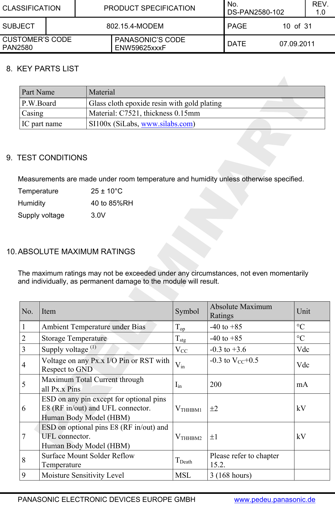
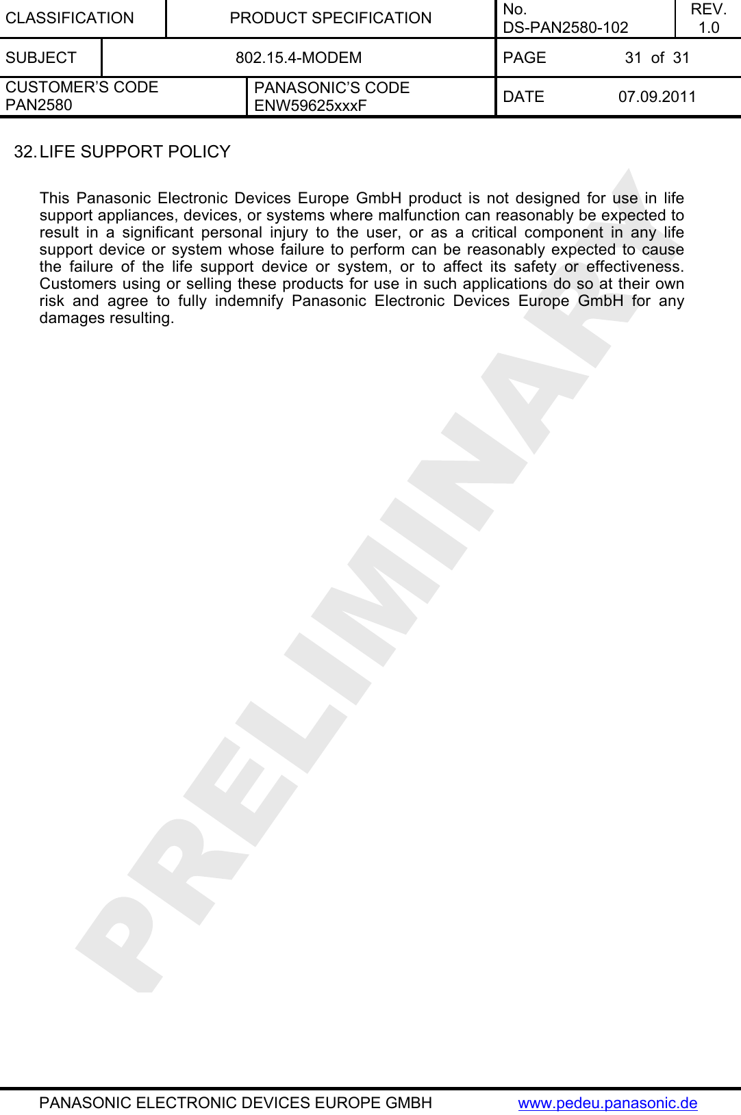
![CLASSIFICATION PRODUCT SPECIFICATION No. DS-PAN2580-102 REV. 1.0 SUBJECT 802.15.4-MODEM PAGE 11 of 31 CUSTOMER’S CODE PAN2580 PANASONIC’S CODE ENW59625xxxF DATE 07.09.2011 PANASONIC ELECTRONIC DEVICES EUROPE GMBH www.pedeu.panasonic.de Notes: (1) The supply voltage must be free of AC ripple voltage (for example from a battery or a low noise regulator output). For noisy supply voltages, please provide a decoupling circuit (for example a ferrite in series connection and a blocking capacitor to ground). The exact ripple tolerance will be published in a later revision. 11. OPERATING CONDITIONS Value No. Item Condition / Remark Symbol Min Typ Max Unit 1 Supply voltage The typical value is recommended VCC 2.7 3.0 3.6 Vdc 2.1 RF Frequency 915MHz Input / Output fRF 902.0 927.6 MHz2.2 RF Frequency 868MHz (3) Input / Output fRF 868.1 868.5 MHz3 Logic Low Level Input Voltage VIL 0 0.6 V 4 Logic High Level Input Voltage VIHVCC–0.6 - V 5 Operating temperature range Top -40 +85 °C 12. DC ELECTRICAL CHARACERISTICS Assume VCC = 3.0V, Tamb = 25°C if nothing else stated Value No. Item Condition / Remark Symbol Min Typ Max Unit 1 Transmit current consumption Transmit Mode ICCT - 68 90 mA 2 Receive current consumption Receive Mode ICCR - 25 30 mA Mode 0(2) ICCSM0 - 0.76 - µA 3 Low power current consumption in sleep mode. Mode 1(2) ICCSM1 - 1.2 - µA Notes: (2) For sleep-mode settings refer to the SNAP Reference Manual [3] (3) In case, when SNAP Software from Synapse is used. Please ask the relevant Product Manager in your region, in case you want to address a different band.](https://usermanual.wiki/Panasonic-Devices-Europe/2580/User-Guide-1604984-Page-11.png)
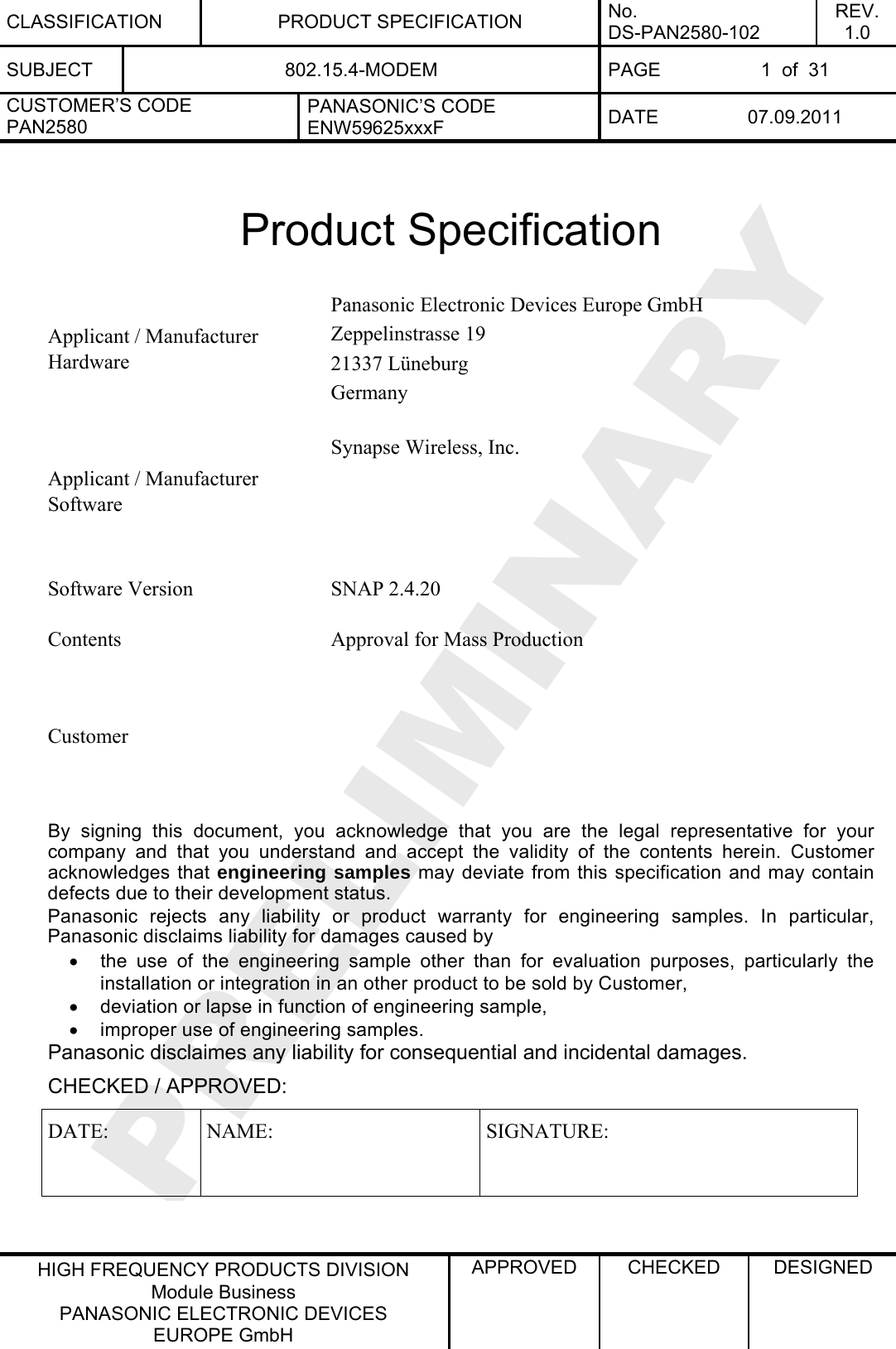
![CLASSIFICATION PRODUCT SPECIFICATION No. DS-PAN2580-102 REV. 1.0 SUBJECT 802.15.4-MODEM PAGE 13 of 31 CUSTOMER’S CODE PAN2580 PANASONIC’S CODE ENW59625xxxF DATE 07.09.2011 PANASONIC ELECTRONIC DEVICES EUROPE GMBH www.pedeu.panasonic.de 14. AC ELECTRICAL CHARACTERISTICS Limit No. Receiver Conditions Min Typ Max Unit 1.1 1% Packet Error Rate (PER), -85dBm required by [1] -92 -95 - 1.2 Wireless M-Bus Mode T1 tbd 1.3 Wireless M-Bus Mode T2 tbd 1.4 Wireless M-Bus Mode S1 tbd 1.5 RX Sensitivity Wireless M-Bus Mode S2 tbd dBm 2 Saturation maximum input level - 5 - dBm 3 Frequency Error Tolerance AFC on, 1% PER - - ±70 kHz 4 Spurious Emissions - - -54 dBm 5 Image Rejection Rejection at the image frequency. IF=937 kHz - -30 - dB 6 RSSI Resolution - ±0.5 - dB 7 ±1-Ch Offset Selectivity - -31 - dB 8 ±2-Ch Offset Selectivity - -35 - dB 9 ≥±3-Ch Offset Selectivity Desired Ref Signal 3 dB above sensitivity, BER < 0.1%. Interferer and desired modulated with 40 kbps ΔF = 20 kHz GFSK with BT = 0.5, channel spacing = 150 kHz - -40 - dB 10 Blocking at 1 MHz Offset - -52 - dB 11 Blocking at 4 MHz Offset - -56 - dB 12 Blocking at 8 MHz Offset Desired Ref Signal 3 dB above sensitivity. Interferer and desired modulated with 40 kbps ΔF = 20 kHz GFSK with BT = 0.5 - -63 - dB Limit No. Transmitter Conditions Min Typ Max Unit 1 Output Power (max) 16 18 20 dBm 2 Power Control Range - 19 - dB 3 Over the Air Data Rate Fixed by Synapse Software - 250 - kbps 4 2nd harmonic maximum output power - -50 -35 dBm 5 3rd harmonic maximum output power - -44 -35 dBm 6 Spurious Emissions <1GHz POUT = 11 dBm - - -54 dBm 7 Spurious Emissions >1GHz excluding harmonics - - -54 dBm](https://usermanual.wiki/Panasonic-Devices-Europe/2580/User-Guide-1604984-Page-13.png)
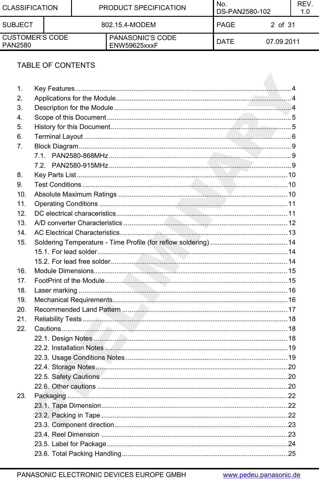
![CLASSIFICATION PRODUCT SPECIFICATION No. DS-PAN2580-102 REV. 1.0 SUBJECT 802.15.4-MODEM PAGE 14 of 31 CUSTOMER’S CODE PAN2580 PANASONIC’S CODE ENW59625xxxF DATE 07.09.2011 PANASONIC ELECTRONIC DEVICES EUROPE GMBH www.pedeu.panasonic.de 15. SOLDERING TEMPERATURE - TIME PROFILE (FOR REFLOW SOLDERING) 15.1. FOR LEAD SOLDER Recommended temp. profile for reflow soldering Temp.[°C] Time [s] 235°C max. 220 ±5°C 200°C150 ±10°C 90 ±30s 10 ±1s 30 +20/-10s 15.2. FOR LEAD FREE SOLDER Our used temp. profile for reflow soldering Temp.[°C] Time [s] 230°C -250°C max. 220°C150°C – 190°C 90 ±30s 30 +20/-10s Reflow permissible cycles: 2 Opposite side reflow is prohibited due to the module weight.](https://usermanual.wiki/Panasonic-Devices-Europe/2580/User-Guide-1604984-Page-14.png)
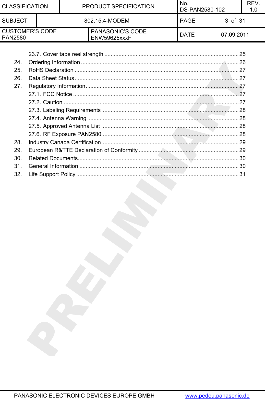
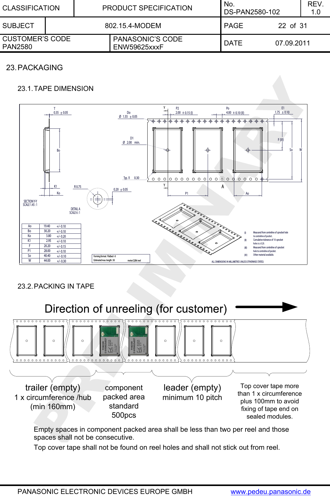
![CLASSIFICATION PRODUCT SPECIFICATION No. DS-PAN2580-102 REV. 1.0 SUBJECT 802.15.4-MODEM PAGE 16 of 31 CUSTOMER’S CODE PAN2580 PANASONIC’S CODE ENW59625xxxF DATE 07.09.2011 PANASONIC ELECTRONIC DEVICES EUROPE GMBH www.pedeu.panasonic.de 18. LASER MARKING The 2D-Barcode contains the following information separated by a semicolon: Value Description Date-code Date code in the format Year - Calender Week - Day of Week – Line - Lot [YYWWDLL] MAC-adress Last 8 digits of the MAC-adress 59625xxx Ordering number [8 signs; without the first 3 digits (ENW) and the last digit (F), please refer also to chapter 24] yyzz The identifier for the hardware release [2 signs, here yy] and the software release [2 signs, here zz] The point on the marking (below left) is the identifier for pin 1 of the module. 19. MECHANICAL REQUIREMENTS No. Item Limit Condition 1 Solderability More than 75% of the soldering area shall be coated by solder Reflow soldering with recommendable temperature profile](https://usermanual.wiki/Panasonic-Devices-Europe/2580/User-Guide-1604984-Page-16.png)
![CLASSIFICATION PRODUCT SPECIFICATION No. DS-PAN2580-102 REV. 1.0 SUBJECT 802.15.4-MODEM PAGE 24 of 31 CUSTOMER’S CODE PAN2580 PANASONIC’S CODE ENW59625xxxF DATE 07.09.2011 PANASONIC ELECTRONIC DEVICES EUROPE GMBH www.pedeu.panasonic.de 23.5. LABEL FOR PACKAGE The label below shows only an example. ENW59625xxxF 500 (3P):PAN2580 Customer Code (1T): Lotcode [YYWWDLL] YY year above 08 WW normal calendar week above 01 D day above 5 (Friday) L line identifier, if more as one actual 1 L lot identifier per day e.g. 1, 2, 3 (1P) Customer Order Code, if any, otherwise put company name on it. (2P) Panasonic Part Number, please refer to chapter 24 Ordering Information (3P) Module type (9D) Datecode as [2xYear, 2xMonth, 2xDay] (Q) Quantity [XXXX], variable (HW/SW) Hardware /Software Release identifier [[G]] Identifier that the product is RoHS conform, please refer to chapter 25.](https://usermanual.wiki/Panasonic-Devices-Europe/2580/User-Guide-1604984-Page-24.png)
![CLASSIFICATION PRODUCT SPECIFICATION No. DS-PAN2580-102 REV. 1.0 SUBJECT 802.15.4-MODEM PAGE 26 of 31 CUSTOMER’S CODE PAN2580 PANASONIC’S CODE ENW59625xxxF DATE 07.09.2011 PANASONIC ELECTRONIC DEVICES EUROPE GMBH www.pedeu.panasonic.de 24. ORDERING INFORMATION No. Ordering part number Description 1 ENW59625A5CF Engineering Sample PAN2580 – 868MHz 802.15.4 Mesh Network Module, which includes Ceramic Antenna and 192kbyte Flash Memory, with 64kbyte used by SNAP core, 64kbyte free for uploadable SNAPpy scripts and 64k reserved Synapse SNAP software included, please refer also to [3]. 2 ENW59625B5CF Engineering Sample PAN2580 – 868MHz 802.15.4 Mesh Network Module, which includes UFL connectorand 192kbyte Flash Memory, with 64kbyte used by SNAP core, 64kbyte free for uploadable SNAPpy scripts and 64k reserved Synapse SNAP software included, please refer also to [3]. 3 ENW59625C5CF Engineering Sample PAN2580 – 868MHz 802.15.4 Mesh Network Module, which includes RF out on SMD pad and 192kbyte Flash Memory, with 64kbyte used by SNAP core, 64kbyte free for uploadable SNAPpy scripts and 64k reserved Synapse SNAP software included, please refer also to [3]. 4 ENW59625A5DF Engineering Sample PAN2580 – 915MHz 802.15.4 Mesh Network Module, which includes Ceramic Antenna and 192kbyte Flash Memory, with 64kbyte used by SNAP core, 64kbyte free for uploadable SNAPpy scripts and 64k reserved Synapse SNAP software included, please refer also to [3]. 5 ENW59625B5DF Engineering Sample PAN2580 - 915MHz 802.15.4 Mesh Network Module, which includes UFL connectorand 192kbyte Flash Memory, with 64kbyte used by SNAP core, 64kbyte free for uploadable SNAPpy scripts and 64k reserved Synapse SNAP software included, please refer also to [3]. 6 ENW59625C5DF Engineering Sample PAN2580 - 915MHz 802.15.4 Mesh Network Module, which includes RF out on SMD pad and 192kbyte Flash Memory, with 64kbyte used by SNAP core, 64kbyte free for uploadable SNAPpy scripts and 64k reserved Synapse SNAP software included, please refer also to [3].](https://usermanual.wiki/Panasonic-Devices-Europe/2580/User-Guide-1604984-Page-26.png)
![CLASSIFICATION PRODUCT SPECIFICATION No. DS-PAN2580-102 REV. 1.0 SUBJECT 802.15.4-MODEM PAGE 30 of 31 CUSTOMER’S CODE PAN2580 PANASONIC’S CODE ENW59625xxxF DATE 07.09.2011 PANASONIC ELECTRONIC DEVICES EUROPE GMBH www.pedeu.panasonic.de 30. RELATED DOCUMENTS For an update, please search in the suitable homepage. [1] IEEE Standard 802.15.4 –2003 Wireless Medium Access Control (MAC) and Physical Layer (PHY) Specifications for Low-Rate Wireless Personal Area Networks (LR-WPANs) [2] Technical Datasheet Si1000/1/2/3/4/5 Rev. 1.0 9/10 You can download the latest datasheet from the SiLabs homepage here. [3] Manual to the Evaluation Kit from Synapse, which fits to module hardware from Panasonic [Downloads: SNAP® Reference Manual Updated 10/2/2008; SNAP Hardware Technical Manual Updated 10/2/2008] Each new release from Synapse, will be posted here. Be sure to be registered free under http://forums.synapse-wireless.com. 31. GENERAL INFORMATION © Panasonic Electronic Devices Europe GmbH 2009. All rights reserved. This product description does not claim to be complete and free of mistakes. Please contact the related product manager with any errata inquries. If we deliver samples to the customer, these samples have the status Engineering Samples. This means, the design of this product is not yet completed. Engineering Samples may be partially or fully functional, and there may be differences published in the Data Sheet. Engineering Samples are not qualified and are not to be used for reliability testing or series production. Disclaimer: Customer acknowledges that samples may deviate from the Data Sheet and may bear defects due to their status of development and the lack of qualification mentioned above. Panasonic Electronic Devices Europe GmbH disclaims any liability or product warranty for Engineering Samples. In particular, Panasonic Electronic Devices Europe GmbH disclaims liability for damages caused by • the use of the Engineering Sample other than for Evaluation Purposes, particularly the installation or integration in an other product to be sold by Customer, • deviation or lapse in function of Engineering Sample, • improper use of Engineering Samples. Panasonic Electronic Devices Europe GmbH disclaimes any liability for consequential and incidental damages. In case of any questions, please contact your local sales partner or the related product manager.](https://usermanual.wiki/Panasonic-Devices-Europe/2580/User-Guide-1604984-Page-30.png)