Panasonic Devices Europe 4561HM 802.15.4-Modem PAN4561 User Manual 1
Panasonic Industrial Devices Europe GmbH 802.15.4-Modem PAN4561 1
UserManual.wiki
>
Panasonic Devices Europe
>
4561HM User Manual
UserMan
Navigation menu
Upload a User Manual
Namespaces
Wiki Guide
HTML
PDF
Info
Views
User Manual
Discussion / Help
Navigation
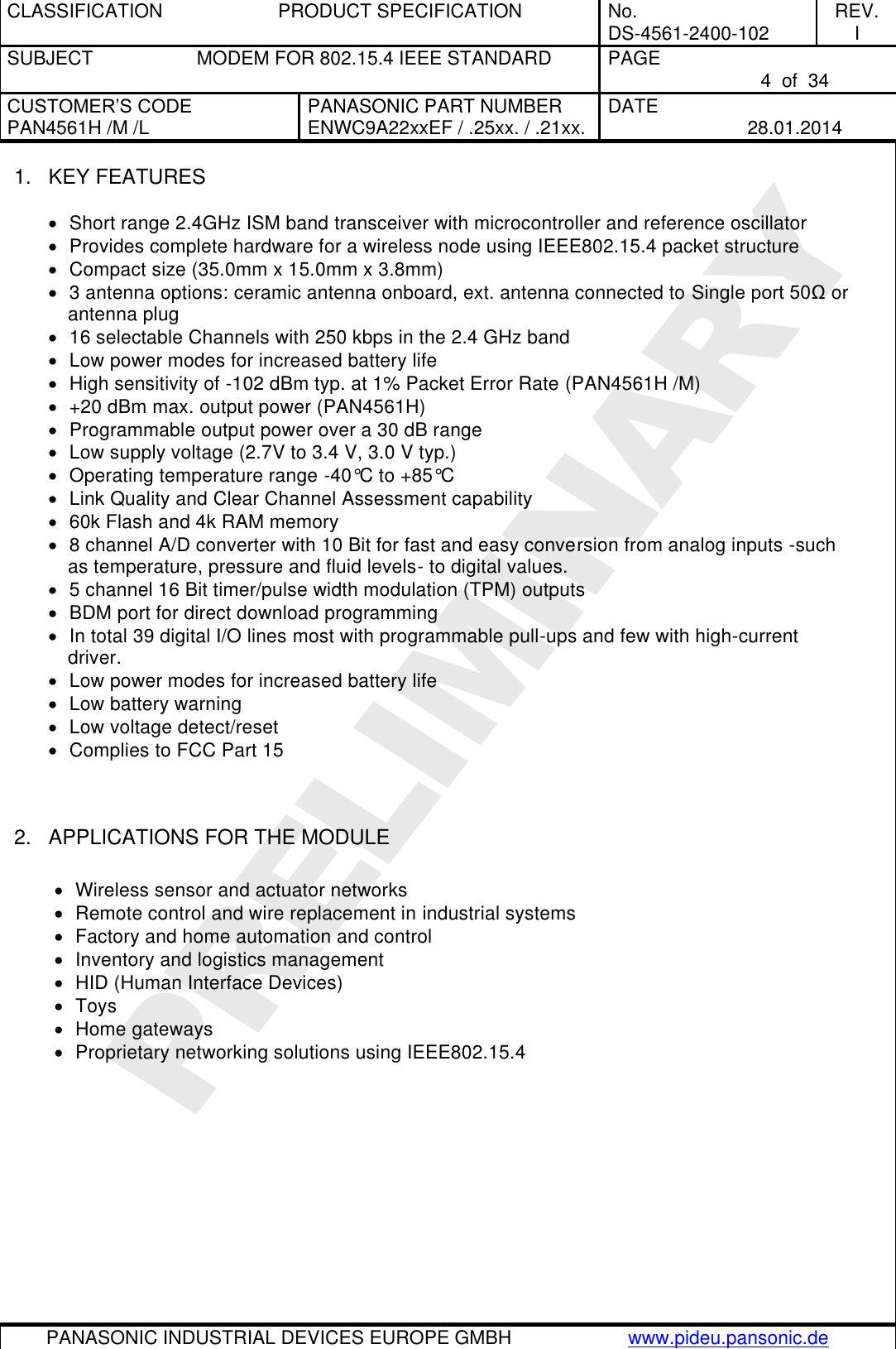
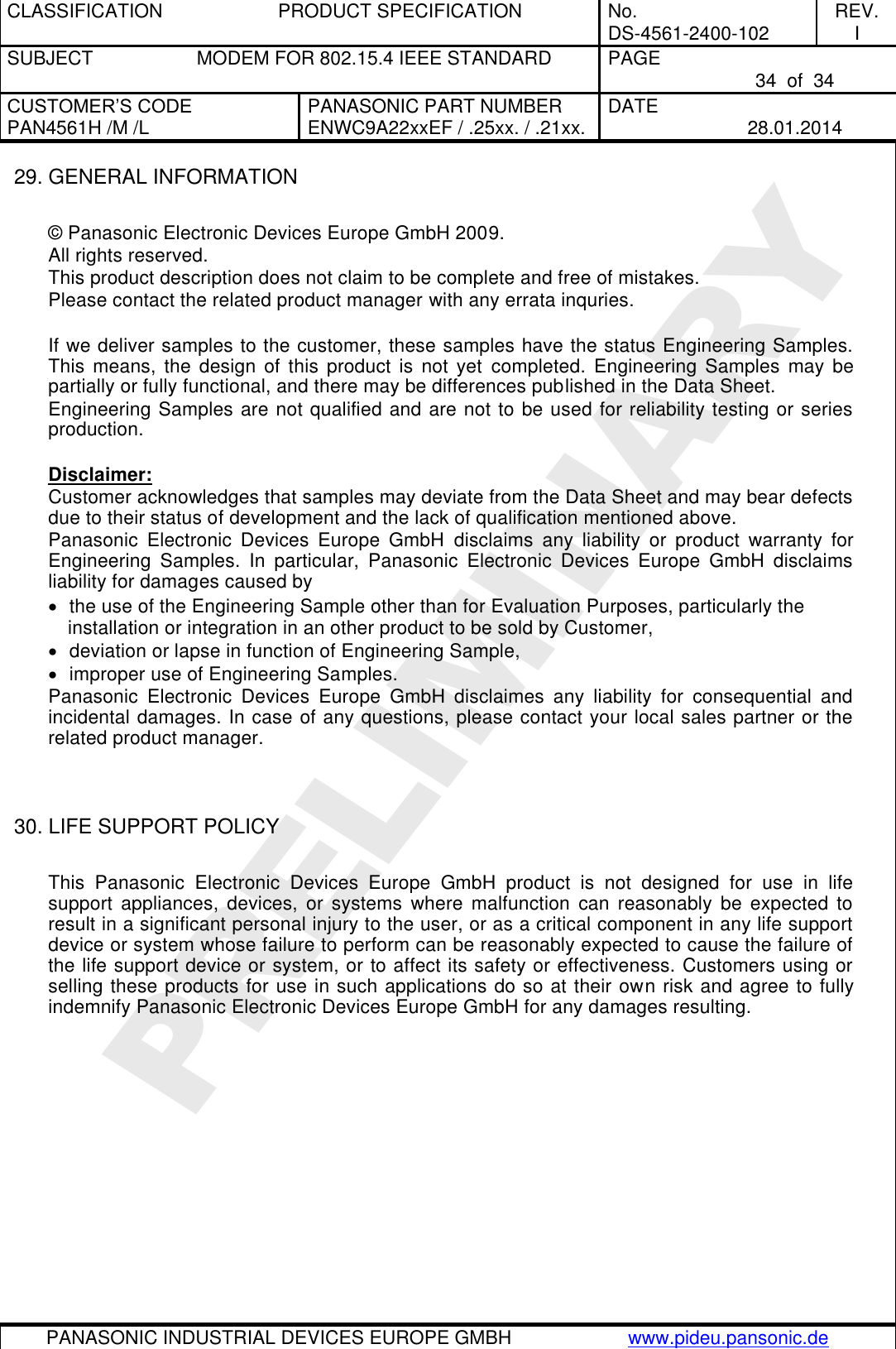
![CLASSIFICATION PRODUCT SPECIFICATION No. DS-4561-2400-102 REV. I SUBJECT MODEM FOR 802.15.4 IEEE STANDARD PAGE 5 of 34 CUSTOMER’S CODE PAN4561H /M /L PANASONIC PART NUMBER ENWC9A22xxEF / .25xx. / .21xx. DATE 28.01.2014 PANASONIC INDUSTRIAL DEVICES EUROPE GMBH www.pideu.pansonic.de PRELIMINARY 3. DESCRIPTION OF THE MODULE The PAN4561with module is a short range, low power, 2.4 GHz ISM band transceiver which includes a complete 802.15.4 physical layer (PHY) modem, designed for the IEEE 802.15.4 wireless standard and an appropriate microcontroller (MCU) with reference oscillator which provides a cost effective solution for short-range data links and networks. There are three versions of PAN4561 available, identified by an H, M or L at the end of series number i.e. PAN4561H, PAN4561M, PAN4561L. The addional letter stands for High, Mid and Low range. All modules in the PAN4561 series are based on the FreeScale MC13213 SOC, fully featured with 39 I/O lines, interchangeable and share a common footprint and software. Mixed node networks can be implemented to conserve power while maximizing range. The PAN4561L is a cost optimized module designed for standard range applications of less than 30 meters. For medium range applications the PAN4561M, is optimized to deliver longer range and conserve power consumption, using a low noise amplifier and 10dBm power amplifier. The PAN4561H is designed for extended range applications, using a low noise amplifier and 20dBm power amplifier. In this document when mentioned PAN4561 the information refers to all three module types. Data which apply only to a specific module (PAN4561 H /M /L) will be marked accordingly. Software solutions available for the PAN4561 are SNAP software from Synapse Wireless Inc. and SN55 software from E-Senza Technologies GmbH which are very easy to use. For detailed information refer to SNAP [9] and and to SN55 [8]. In addition, you are free to develop also your own application on the software package from Freescale™, e.g. SMAC, for details please refer to [4], [5], [6] and [7]. For the Integrated Development Environment (IDE) the MetrowerksPTM PCodeWarrior IDE from Hwww.metrowerks.com is required. For device flash programming via the BDM port of PAN4561 the USB HCS08/HCS12 Multilink from www.pemicro.com is recommended.](https://usermanual.wiki/Panasonic-Devices-Europe/4561HM/User-Guide-2220609-Page-5.png)
![CLASSIFICATION PRODUCT SPECIFICATION No. DS-4561-2400-102 REV. I SUBJECT MODEM FOR 802.15.4 IEEE STANDARD PAGE 6 of 34 CUSTOMER’S CODE PAN4561H /M /L PANASONIC PART NUMBER ENWC9A22xxEF / .25xx. / .21xx. DATE 28.01.2014 PANASONIC INDUSTRIAL DEVICES EUROPE GMBH www.pideu.pansonic.de PRELIMINARY 4. SCOPE OF THIS DOCUMENT This product specification applies to the IEEE 802.15.4 Standard modem ENWC9A22xxEF. The xx is the indicator for different versions (refer to chapter 25 Ordering Information). The platform used is the MC13213 from the US company Freescale Semiconductor www.freescale.com/ [2], [3] 5. HISTORY FOR THIS DOCUMENT Revision Date Modification / Remarks A 09.03.2009 Initial draft version B 20.03.2009 Some minor changes, regarding the specification wording C 29.04.2009 Change chapter 24, ordering code for Synapse software. Change the crystal value from 26MHz to 16MHz in chapter block diagram, as it was a mistake in this document. D 08.09.2009 Change chapter 7, regarding hardware dependent software. E 06.04.2010 Datasheet updated for 4561 PCB revision C (Prelimenary) F 31.05.2010 Added chapter 27 Regulatory Information. Minor changes of module parameters. G 06.08.2010 Added data for PAN4561M and PAN4561L H 17.09.2010 Changed receive current consumption values. I 28.01.2014 Add FCC marking](https://usermanual.wiki/Panasonic-Devices-Europe/4561HM/User-Guide-2220609-Page-6.png)
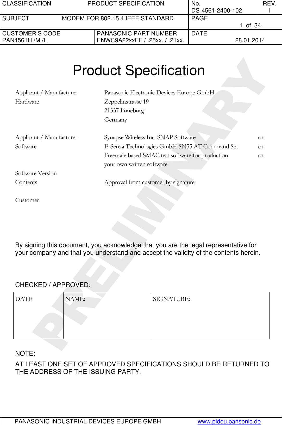
![CLASSIFICATION PRODUCT SPECIFICATION No. DS-4561-2400-102 REV. I SUBJECT MODEM FOR 802.15.4 IEEE STANDARD PAGE 7 of 34 CUSTOMER’S CODE PAN4561H /M /L PANASONIC PART NUMBER ENWC9A22xxEF / .25xx. / .21xx. DATE 28.01.2014 PANASONIC INDUSTRIAL DEVICES EUROPE GMBH www.pideu.pansonic.de PRELIMINARY 6. TERMINAL LAYOUT Antenna35.0 mm15.0 mmHeight3.8 mmTop View2232Pad 1 = 4 x 1.30mm x 1.30mmPad 2 = 58 x 0.60mm x 1.30mm153 Please refer also to the MC1321x technical data sheet and reference manual, which is given in [2] and [3] in the chapter “Related Documents”. Pin No. Pin Pin Type Description 1 GND I/O Ground 2 PTD4 / TPM2CH1 Dig. I/O MCU Port D Bit 4 / TPM2 Channel 1 3 PTD5 / TPM2CH2 Dig. I/O MCU Port D Bit 5 / TPM2 Channel 2 4 PTD6 / TPM2CH3 Dig. I/O MCU Port D Bit 6 / TPM2 Channel 3 5 PTD7 / TPM2CH4 Dig. I/O MCU Port D Bit 7 / TPM2 Channel 4 6 PTD2 / TPM1CH2 Dig. I/O MCU Port D Bit 2 / TPM1 Channel 2 7 NC Not connected – leave open 8 PTC0 / TXD2 Dig. I/O MCU Port C Bit 0 / SCI2 TX data out (UART2) 9 PTC1 / RXD2 Dig. I/O MCU Port C Bit 1 / SCI2 RX data in (UART2) 10 PTC2 / SDA1 Dig. I/O MCU Port C Bit 1/ IIC bus data (I²C) 11 PTC3 / SCL1 Dig. I/O MCU Port C Bit 1/ IIC bus clock (I²C) 12 PTB0 / AD1P0 I/O MCU Port B Bit 0 / ATD analog Channel 0 13 PTB1 / AD1P1 I/O MCU Port B Bit 1 / ATD analog Channel 1 14 PTB2 / AD1P2 I/O MCU Port B Bit 2 / ATD analog Channel 2 15 PTB3 / AD1P3 I/O MCU Port B Bit 3 / ATD analog Channel 3 16 PTB4 / AD1P4 I/O MCU Port B Bit 4 / ATD analog Channel 4 17 PTB5 / AD1P5 I/O MCU Port B Bit 5 / ATD analog Channel 5 18 PTB6 / AD1P6 I/O MCU Port B Bit 6 / ATD analog Channel 6 19 PTB7 / AD1P7 I/O MCU Port B Bit 7 / ATD analog Channel 7 20 VREFH I MCU high reference voltage for ATD 21 VREFL I MCU low reference voltage for ATD 22 GND I/O Ground 23 Vcc Power I Modem voltage regulators’ input 24 Vcc Power I Modem voltage regulators’ input 25 PTG1 / XTAL Dig. I/O / O MCU Port G Bit 1 / Crystal oscillator output P(2)P](https://usermanual.wiki/Panasonic-Devices-Europe/4561HM/User-Guide-2220609-Page-7.png)
![CLASSIFICATION PRODUCT SPECIFICATION No. DS-4561-2400-102 REV. I SUBJECT MODEM FOR 802.15.4 IEEE STANDARD PAGE 8 of 34 CUSTOMER’S CODE PAN4561H /M /L PANASONIC PART NUMBER ENWC9A22xxEF / .25xx. / .21xx. DATE 28.01.2014 PANASONIC INDUSTRIAL DEVICES EUROPE GMBH www.pideu.pansonic.de PRELIMINARY Pin No. Pin Pin Type Description 26 PTG2 / EXTAL Dig. I/O / I MCU Port G Bit 2 / Crystal oscillator input P(2)P (3).(4) 27 RESET Dig. I MCU reset. Active low 28 CLKO Dig. O Programmable Clock Output (default: 32,768 kHz)P (3) 29 GPIO2 Dig. I/O GPIO2 from RF transceiver unit 30 PTG0 / BKGND / MS Dig. I/O MCU Port G Bit 0 / Background / Mode Select P(1)P 31 GPIO1 Dig. I/O GPIO1 from RF transceiver unit 32 GND I/O Ground 33 VDDA Power O Modem analog regulated supply output - leave open 34 PTA7 / KBI1P7 Dig. I/O MCU Port A Bit 7 / Keyboard Input Bit 7 35 PTA6 / KBI1P6 Dig. I/O MCU Port A Bit 6 / Keyboard Input Bit 6 36 PTA5 / KBI1P5 Dig. I/O MCU Port A Bit 5 / Keyboard Input Bit 5 37 PTA4 / KBI1P4 Dig. I/O MCU Port A Bit 4 / Keyboard Input Bit 4 38 PTA3 / KBI1P3 Dig. I/O MCU Port A Bit 3 / Keyboard Input Bit 3 39 PTA2 / KBI1P2 Dig. I/O MCU Port A Bit 2 / Keyboard Input Bit 2 40 PTA1 / KBI1P1 Dig. I/O MCU Port A Bit 1 / Keyboard Input Bit 1 41 PTA0 / KBI1P0 Dig. I/O MCU Port A Bit 0 / Keyboard Input Bit 0 42 PTC7 / GPIO Dig. I/O MCU Port C Bit 7 (GPIO) 43 PTC6 / GPIO Dig. I/O MCU Port C Bit 6 (GPIO) 44 PTC5 / GPIO Dig. I/O MCU Port C Bit 5 (GPIO) 45 PTC4 / GPIO Dig. I/O MCU Port C Bit 4 (GPIO) 46 PTE0 / TXD1 Dig. I/O MCU Port E Bit 0 / SCI1 TX data out (UART1) 47 PTE1 / RXD1 Dig. I/O MCU Port E Bit 1/ SCI1 RX data in (UART1) 48 GPIO5 Dig. I/O GPIO5 from RF transceiver unit 49 GPIO6 Dig. I/O GPIO6 from RF transceiver unit 50 GPIO7 Dig. I/O GPIO7 from RF transceiver unit 51 NC Not connected – leave open 52 NC Not connected – leave open 53 - 54 GND I/O Ground 55 EXANT I/O Pin for external antenna (50 ) 56 - 62 GND I/O Ground Note: (1) PTG0 is output only. Pin is I/O when used as BDM function. (2) Full I/O when not used as clock source. Please refer also to [2]. (3) CLKO (Pin 28) and PTG2/EXTAL (Pin 26) must be connected when the programmable clock derived from the internal 16 MHz crystal. Do not connect when the clock derived from Internal Reference Generator in MC13213. (4) PTG2 / EXTAL is not accessible with E-Senza software Port PTA, PTB, PTC, PTD, PTE, PTG have internal software controlled pull-up resistors. For detailed information refer to [3]. All I/O pins of port PTC are high current pins. The maximum current for all pins together must not exceed 60mA. A continuous current of 7mA, and 25mA burst for each port pin must not be exceeded. For detailed information refer to [3].](https://usermanual.wiki/Panasonic-Devices-Europe/4561HM/User-Guide-2220609-Page-8.png)
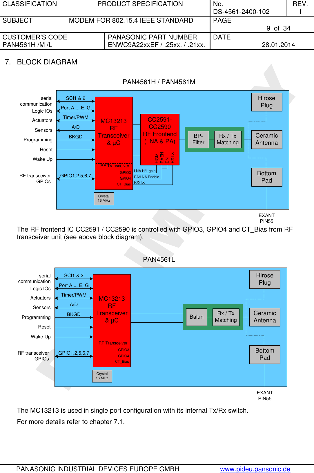
![CLASSIFICATION PRODUCT SPECIFICATION No. DS-4561-2400-102 REV. I SUBJECT MODEM FOR 802.15.4 IEEE STANDARD PAGE 10 of 34 CUSTOMER’S CODE PAN4561H /M /L PANASONIC PART NUMBER ENWC9A22xxEF / .25xx. / .21xx. DATE 28.01.2014 PANASONIC INDUSTRIAL DEVICES EUROPE GMBH www.pideu.pansonic.de PRELIMINARY 7.1. SOFTWARE DIFFERENCES 7.1.1. Test / Demo software Modules with Test / Demo software are intended for customer writing their own software for the module. The module contains software but only with a small instruction set. The front end IC CC2591 / CC2590 is enabled and disabled with RF transceiver GPIO4. Set high to enable and low to disable the chip. Please refer to appendix [10]. The LNA has two modes, high and low gain. This mode is controlled with RF transceiver GPIO3. Set it high for high gain and low for low gain mode. Please refer to appendix [10]. The RXTX signal on CC2591 and CC2590 is controlled by CT_Bias pin. Please refer to appendix [10]. 7.1.2. E-Senza software Modules with E-Senza software can be used to set up a measurement system easily with a GUI. With this software it is not possible to set the modules into energy saving sleep mode. 7.1.3. Synapse software With Synapse software the customer writes his own scripts based on easy to learn, Phyton based, programming language. This software is very flexible and can be used for multiple applications. The control of PA/LNA is primary supported from version SNAPv2.2.15 or newer. The Synapse software on the module provides several initializing parameters called NV-parameters. These are already set. For detailed information refer to SNAP Reference Manual [9]. To comply to FCC regulation the power level has to be reduced to txPwr(14) for PAN4561H. For detailed information on FCC compliance refer to chapter 27. Regulatory Information. Synapse Wireless Inc. probably releases two to three times a year a new SNAP release. PAN4561 modules will always be shipped with the newest SNAP version.](https://usermanual.wiki/Panasonic-Devices-Europe/4561HM/User-Guide-2220609-Page-10.png)
![CLASSIFICATION PRODUCT SPECIFICATION No. DS-4561-2400-102 REV. I SUBJECT MODEM FOR 802.15.4 IEEE STANDARD PAGE 11 of 34 CUSTOMER’S CODE PAN4561H /M /L PANASONIC PART NUMBER ENWC9A22xxEF / .25xx. / .21xx. DATE 28.01.2014 PANASONIC INDUSTRIAL DEVICES EUROPE GMBH www.pideu.pansonic.de PRELIMINARY 8. KEY PARTS LIST Part Name Material P.W.Board Glass cloth epoxide resin with gold plating Casing Material: BZn15-20, thickness 0.15mm IC part name MC13213 (Freescale www.freescale.com/) All information are based on [2] chapter 28 CC2591 / CC2590 (Texas Instruments www.ti.com) All information are based on [10] chapter 27. 9. TEST CONDITIONS Measurements are made under room temperature and humidity unless otherwise specified. Temperature 25 ± 10°C Humidity 40 to 85%RH Supply voltage 3.0V](https://usermanual.wiki/Panasonic-Devices-Europe/4561HM/User-Guide-2220609-Page-11.png)
![CLASSIFICATION PRODUCT SPECIFICATION No. DS-4561-2400-102 REV. I SUBJECT MODEM FOR 802.15.4 IEEE STANDARD PAGE 12 of 34 CUSTOMER’S CODE PAN4561H /M /L PANASONIC PART NUMBER ENWC9A22xxEF / .25xx. / .21xx. DATE 28.01.2014 PANASONIC INDUSTRIAL DEVICES EUROPE GMBH www.pideu.pansonic.de PRELIMINARY 10. ABSOLUT MAXIMUM RATINGS The maximum ratings may not be exceeded under any circumstances (not even momentarily) as permanent damage to the module will result. No. Item Symbol Absolute Maximum Ratings Unit 1 Supply voltage VBCCB -0.3 to +3.6 Vdc 2 Ripple on VBCCB VccBripB tbd (2) (ripple frequency ≥200kHz) mVpp 3 Digital input voltages VBinB -0.3 to VBCCB+0.3 Vdc 4 Instantaneous maximum current Single pin limit for all digital I/O pins P(1)P IBDB 25 mAdc 5 Storage temperature range TBstgB -40 to +105 °C 6 Operating temperature range TBopB -40 to +85 °C 7 RF Input Power PBmaxB 10 dBm 8 ESD on any pin except for pin 32 EXANT. Human Body Model (HBM) VBTHHBMB 2 kV 9 Moisture Sensitivity Level MSL 3 (168 hours) Notes: (1) Input must be current limited to the value specified. Please refer also to [2]. (2) The supply voltage must be free of AC ripple voltage (for example from a battery or a low noise regulator output). For noisy supply voltages, please provide a decoupling circuit (for example a ferrite in series connection and a blocking capacitor to ground of at least 47µF directly at the module). The exact ripple tolerance will be published in a later revision. 11. OPERATING CONDITIONS No. Item Condition / Remark Symbol Value Unit Min Typ Max 1 Supply voltage The typical value is recommended VBCCB 2.7 3.0 3.4 Vdc 2 RF Input Frequency fBinB 2400 2483.5 MHz 3 Return loss of load at pin 55 EXANT Receive/Transmit Mode to 50Ω reference load a -9.5 dB 4 Logic Input Voltage Low VBILB 0 0.3xVBCCB V 5 Logic Input Voltage High VBIHB 0.7xVBCCB VBCCB V 6 SPI clock rate The typical value is recommended fBSPIB - - 8.0 MHz 7 Operating temperature range TBopB -40 +85 °C](https://usermanual.wiki/Panasonic-Devices-Europe/4561HM/User-Guide-2220609-Page-12.png)
![CLASSIFICATION PRODUCT SPECIFICATION No. DS-4561-2400-102 REV. I SUBJECT MODEM FOR 802.15.4 IEEE STANDARD PAGE 13 of 34 CUSTOMER’S CODE PAN4561H /M /L PANASONIC PART NUMBER ENWC9A22xxEF / .25xx. / .21xx. DATE 28.01.2014 PANASONIC INDUSTRIAL DEVICES EUROPE GMBH www.pideu.pansonic.de PRELIMINARY 12. DC ELECTRICAL CHARACERISTICS Assume VBCCB = 3.0V, TBambB = 25°C if nothing else stated No. Item Condition / Remark Symbol Module type Value Unit Min Typ Max 1 Transmit current consumption Transmit Mode(8) IBCCTB PAN4561H @ 20dBm(1) - 200 240 mA PAN4561M @ 10dBm - 72 80 PAN4561L @ 0dBm - 43 50 2 Receive current consumption Receive Mode(8)(8) IBCCRB PAN4561H - 60 70 mA PAN4561M - 60 70 PAN4561L - 60 70 3 Low power current consumption Off(2)(4)(4) IBleakageB PAN4561H - 0.55 ‘- µA PAN4561M - 0.55 ‘- PAN4561L - 0.55 ‘- Sleep(2)(5)(9) IBCCHB PAN4561H - 2.2 ‘- µA PAN4561M - 2.2 ‘- PAN4561L - 2.2 ‘- Standby(2)(3)(6)(9) IBCCDB PAN4561H - 36,3 ‘- µA PAN4561M - 36,3 ‘- PAN4561L - 36,3 ‘- Idle(7)(7) IBCCIB PAN4561H - 1.6 ‘- mA PAN4561M - 1.6 ‘- PAN4561L - 1.6 ‘- 4 digital I/O pin characteristics Please refer to [2] 6.3.1 MCU DC Characteristics 6 Low voltage warning/detection Please refer to [2] 6.3.1 MCU DC Characteristics Power on reset re-arm voltage Notes: (1) SPI Register 12 has a value of 0xDC which sets output power to nominal value. (2) To attain specified low power current, all GPIOs and other digital IO must be handled properly. Set all port pins as output low when left open or as input when connected to defined level. Detailed descriptions can be found at [2] at section 7.2 Low Power Considerations. (3) CLKO frequency is set to a default value of 32.786 kHz. (4) Off mode: Stop1 on µC, Modem off [3]. Wakeup by IRQ or Reset (5) Sleep mode: Stop2 + RTC on µC, Modem Hibernate [3]. Wakeup by IRQ, Reset or Real-Time-Interrupt (6) Standby mode: Stop3 + RTC on µC, Modem Doze [3]. Wakeup by IRQ, Reset, RTI or Keyboard Interrupt (7) Idle mode: µC runs at reduced 2 MHz clock, Modem is in Idle state [3] (8) µC runs in full speed mode (16 MHz clock) (9) RTC requires external 32 kHz crystal. Without RTC 300nA less current](https://usermanual.wiki/Panasonic-Devices-Europe/4561HM/User-Guide-2220609-Page-13.png)
![CLASSIFICATION PRODUCT SPECIFICATION No. DS-4561-2400-102 REV. I SUBJECT MODEM FOR 802.15.4 IEEE STANDARD PAGE 14 of 34 CUSTOMER’S CODE PAN4561H /M /L PANASONIC PART NUMBER ENWC9A22xxEF / .25xx. / .21xx. DATE 28.01.2014 PANASONIC INDUSTRIAL DEVICES EUROPE GMBH www.pideu.pansonic.de PRELIMINARY 13. A/D CONVERTER CHARACTERISTICS No Item Remark 1 ATD characteristics Please refer to [2] 6.3.3 MCU ATD Characteristics 2 ATD timing/performance characteristics Please refer to [2] 6.3.3 MCU ATD Characteristics The A/D high reference voltage VREFH is connected to pin 20 (VREFH). Connect this signal primarily to Vcc. The A/D low reference voltage VREFL is connected to pin 21 (VREFL). Connect this signal primarily to GND 14. AC ELECTRICAL CHARACTERISTICS VBCC B= 3.0V, TBambB = 25°C, 50 load at EXANT, for all channel numbers 11,12,..., 26 according to [1] No Receiver Module type Limit Unit Min Typ Max 1 Sensitivity for 1% Packet Error Rate (PER), -85dBm required by [1] PAN4561H -85 -102 -105 dBm PAN4561M -85 -102 -105 PAN4561L -85 -92 - 2 Saturation (maximum input level) All - 10 - dBm 3 Adjacent Channel Interference for 1% PER All - 29 - dB (5MHz; desired signal -82dBm) 4 Alternate Channel Interference for 1% PER All - 40 - dB (10MHz; desired signal -82dBm) 5 Frequency Error Tolerance All - - 200 kHz 6 Symbol Rate Error Tolerance All - 80 ppm 8 Spurious Emissions <1GHz All - - -57 dBm 9 Spurious Emissions >1GHz All - - -47 dBm](https://usermanual.wiki/Panasonic-Devices-Europe/4561HM/User-Guide-2220609-Page-14.png)
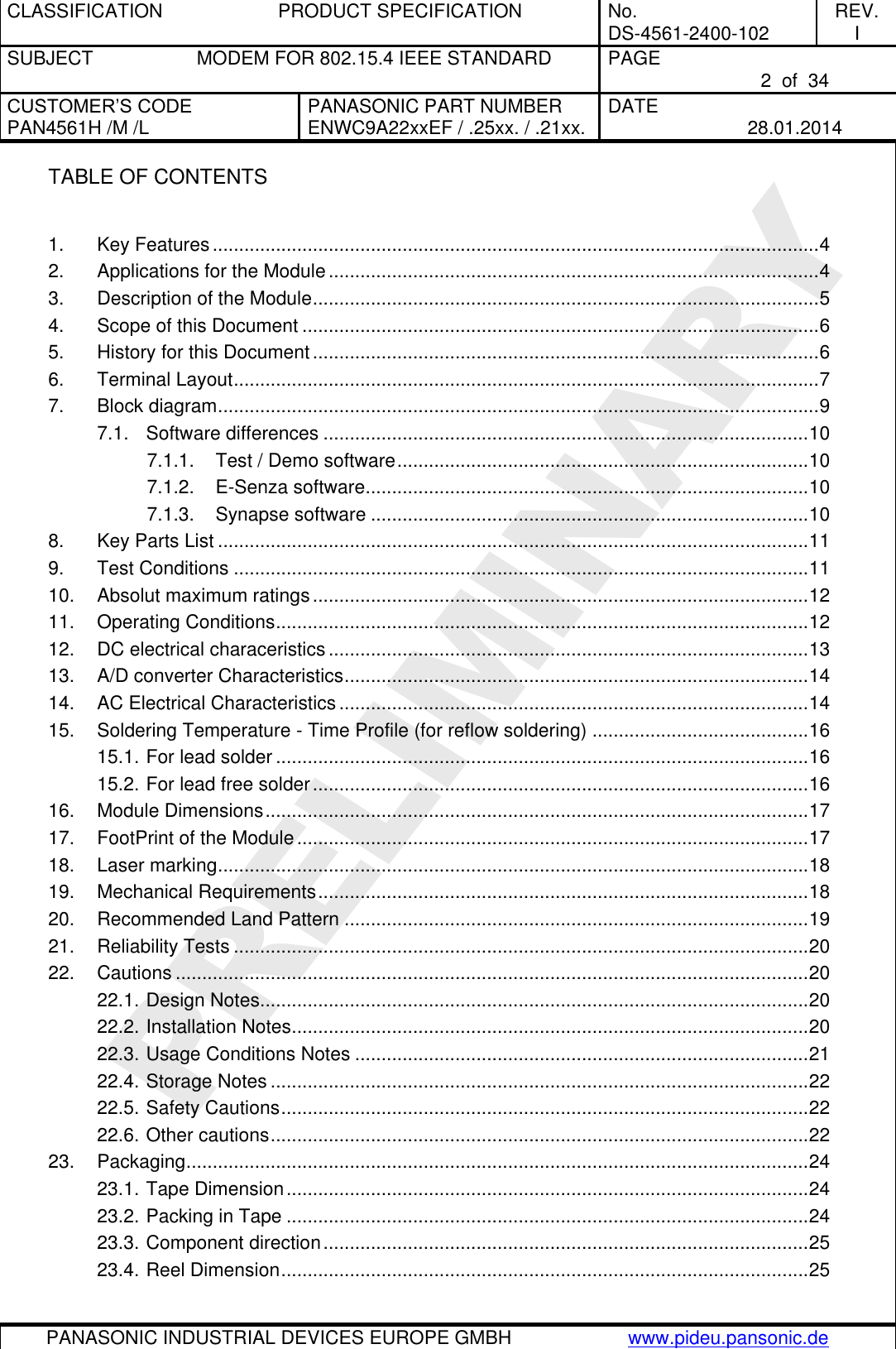
![CLASSIFICATION PRODUCT SPECIFICATION No. DS-4561-2400-102 REV. I SUBJECT MODEM FOR 802.15.4 IEEE STANDARD PAGE 16 of 34 CUSTOMER’S CODE PAN4561H /M /L PANASONIC PART NUMBER ENWC9A22xxEF / .25xx. / .21xx. DATE 28.01.2014 PANASONIC INDUSTRIAL DEVICES EUROPE GMBH www.pideu.pansonic.de PRELIMINARY 15. SOLDERING TEMPERATURE - TIME PROFILE (FOR REFLOW SOLDERING) 15.1. FOR LEAD SOLDER Recommended temp. profile for reflow soldering Temp.[°C] Time [s] 235°C max. 220 5°C 200°C 150 10°C 90 30s 10 1s 30 +20/-10s 15.2. FOR LEAD FREE SOLDER Our used temp. profile for reflow soldering Temp.[°C] Time [s] 230°C -250°C max. 220°C 150°C – 190°C 90 30s 30 +20/-10s Reflow permissible cycles: 2 Opposite side reflow is prohibited due to the module weight.](https://usermanual.wiki/Panasonic-Devices-Europe/4561HM/User-Guide-2220609-Page-16.png)
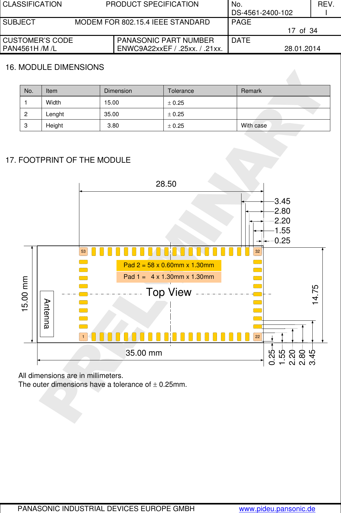
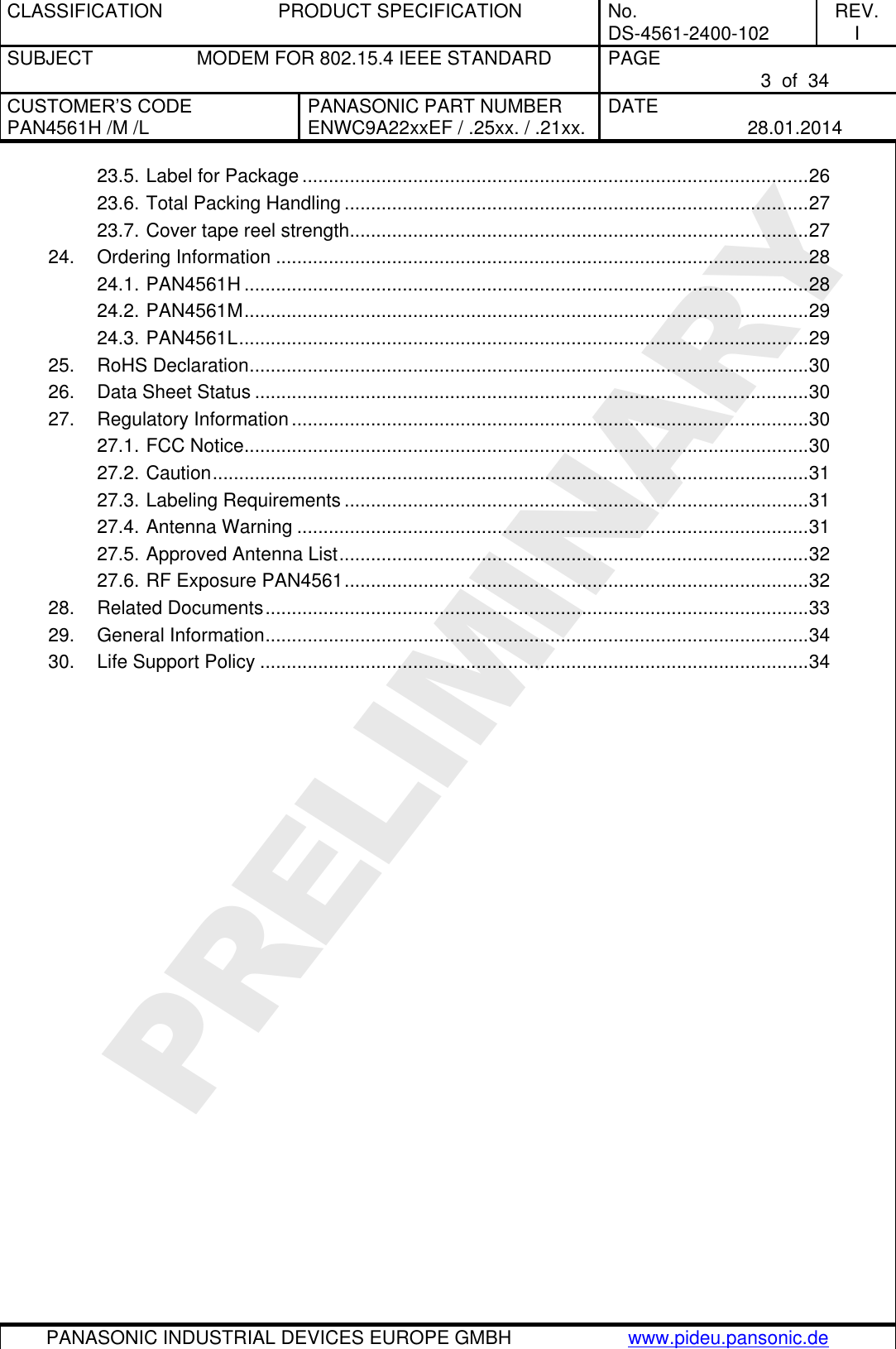
![CLASSIFICATION PRODUCT SPECIFICATION No. DS-4561-2400-102 REV. I SUBJECT MODEM FOR 802.15.4 IEEE STANDARD PAGE 18 of 34 CUSTOMER’S CODE PAN4561H /M /L PANASONIC PART NUMBER ENWC9A22xxEF / .25xx. / .21xx. DATE 28.01.2014 PANASONIC INDUSTRIAL DEVICES EUROPE GMBH www.pideu.pansonic.de PRELIMINARY 18. LASER MARKING Antenna35.0 mm15.0 mm2232531ENWC9A2xxxEFPAN4561v ESyy Serial-No.zz Date-codeFCC ID: T7V4561HM The 2D-Barcode contains the following information separated by a semicolon: Value Description Date-code Date code in the format Year-Month-Day [YYMMDD] Serial-No. Serial number [7 signs, here 0000000] ENWC9A2xxxEF Ordering number [8 signs; without ENW and F, please refer also to chapter 24] v Module type: H, M or L (for High, Mid and Low power) yy The identifier for the hardware release [2 signs, here yy] zz The identifier for the software release [2 signs, here zz] The point on the marking (below left) is the identifier for pin 1 of the module. 19. MECHANICAL REQUIREMENTS No. Item Limit Condition 1 Solderability More than 75% of the soldering area shall be coated by solder Reflow soldering with recommendable temperature profile](https://usermanual.wiki/Panasonic-Devices-Europe/4561HM/User-Guide-2220609-Page-18.png)
![CLASSIFICATION PRODUCT SPECIFICATION No. DS-4561-2400-102 REV. I SUBJECT MODEM FOR 802.15.4 IEEE STANDARD PAGE 26 of 34 CUSTOMER’S CODE PAN4561H /M /L PANASONIC PART NUMBER ENWC9A22xxEF / .25xx. / .21xx. DATE 28.01.2014 PANASONIC INDUSTRIAL DEVICES EUROPE GMBH www.pideu.pansonic.de PRELIMINARY 23.5. LABEL FOR PACKAGE The label below shows only an example. (1T): Lotcode [YYWWDLL] YY year today 10 WW normal calendar week today 01 D day today 5 (Friday) L line identifier, if more as one actual 1 L lot identifier per day e.g. 1, 2, 3… (1P) Customer Order Code, if any, otherwise put company name on it. (2P) Panasonic Part Number (3P) Module type [PAN4561H, PAN4561M or PAN4561L] (9D) Datecode as [2xYear, 2xMonth, 2xDay] (Q) Quantity [XXXX], variable (HW/SW) Hardware /Software Release identifier [[G]] Identifier that the product is RoHS conform, please refer to chapter 25. ENWC9A22xxEF Customer Code (3P):PAN4561v](https://usermanual.wiki/Panasonic-Devices-Europe/4561HM/User-Guide-2220609-Page-26.png)
![CLASSIFICATION PRODUCT SPECIFICATION No. DS-4561-2400-102 REV. I SUBJECT MODEM FOR 802.15.4 IEEE STANDARD PAGE 28 of 34 CUSTOMER’S CODE PAN4561H /M /L PANASONIC PART NUMBER ENWC9A22xxEF / .25xx. / .21xx. DATE 28.01.2014 PANASONIC INDUSTRIAL DEVICES EUROPE GMBH www.pideu.pansonic.de PRELIMINARY 24. ORDERING INFORMATION 24.1. PAN4561H No. Ordering part number Description 1 ENWC9A22A4EF Engineering Sample PAN4561H 802.15.4 Mesh Network Module, which includes Ceramic Antenna, Low Noise Amplifier, up to +20dBm Power Amplifier and 60kBit Flash Memory. Synapse SNAP software included, please refer also to [9]. 2 ENWC9A22B4EF Engineering Sample PAN4561H 802.15.4 Mesh Network Module, which includes UFL connector, Low Noise Amplifier, up to +20dBm Power Amplifier and 60kBit Flash Memory. Synapse SNAP software included, please refer also to [9]. 3 ENWC9A22C4EF Engineering Sample PAN4561H 802.15.4 Mesh Network Module, which includes RF out on SMD pad, Low Noise Amplifier, up to +20dBm Power Amplifier and 60kBit Flash Memory. Synapse SNAP software included, please refer also to [9]. 4 ENWC9A22A2EF Same as number 1, but with Software: SN55 from E-Senza, please refer also to [8] 5 ENWC9A22B2EF Same as number 2, but with Software: SN55 from E-Senza, please refer also to [8] 6 ENWC9A22C2EF Same as number 3, but with Software: SN55 from E-Senza, please refer also to [8] 7 ENWC9A22A1EF Same as number 1, but with Freescale based SMAC test software. 8 ENWC9A22B1EF Same as number 2, but with Freescale based SMAC test software. 9 ENWC9A22C1EF Same as number 3, but with Freescale based SMAC test software.](https://usermanual.wiki/Panasonic-Devices-Europe/4561HM/User-Guide-2220609-Page-28.png)
![CLASSIFICATION PRODUCT SPECIFICATION No. DS-4561-2400-102 REV. I SUBJECT MODEM FOR 802.15.4 IEEE STANDARD PAGE 29 of 34 CUSTOMER’S CODE PAN4561H /M /L PANASONIC PART NUMBER ENWC9A22xxEF / .25xx. / .21xx. DATE 28.01.2014 PANASONIC INDUSTRIAL DEVICES EUROPE GMBH www.pideu.pansonic.de PRELIMINARY 24.2. PAN4561M No. Ordering part number Description 1 ENWC9A25A4EF Engineering Sample PAN4561M 802.15.4 Mesh Network Module, which includes Ceramic Antenna, Low Noise Amplifier, up to +10dBm Power Amplifier and 60kBit Flash Memory. Synapse SNAP software included, please refer also to [9]. 2 ENWC9A25B4EF Engineering Sample PAN4561M 802.15.4 Mesh Network Module, which includes UFL connector, Low Noise Amplifier, up to +10dBm Power Amplifier and 60kBit Flash Memory. Synapse SNAP software included, please refer also to [9]. 3 ENWC9A25C4EF Engineering Sample PAN4561M 802.15.4 Mesh Network Module, which includes RF out on SMD pad, Low Noise Amplifier, up to +10dBm Power Amplifier and 60kBit Flash Memory. Synapse SNAP software included, please refer also to [9]. 4 ENWC9A25A2EF Same as number 1, but with Software: SN55 from E-Senza, please refer also to [8] 5 ENWC9A25B2EF Same as number 2, but with Software: SN55 from E-Senza, please refer also to [8] 6 ENWC9A25C2EF Same as number 3, but with Software: SN55 from E-Senza, please refer also to [8] 7 ENWC9A25A1EF Same as number 1, but with Freescale based SMAC test software. 8 ENWC9A25B1EF Same as number 2, but with Freescale based SMAC test software. 9 ENWC9A25C1EF Same as number 3, but with Freescale based SMAC test software. 24.3. PAN4561L No. Ordering part number Description 1 ENWC9A21A4EF Engineering Sample PAN4561L 802.15.4 Mesh Network Module, which includes Ceramic Antenna, up to 0dBm output power and 60kBit Flash Memory. Synapse SNAP software included, please refer also to [9]. 2 ENWC9A21B4EF Engineering Sample PAN4561L 802.15.4 Mesh Network Module, which includes UFL connector, up to 0dBm output power and 60kBit Flash Memory. Synapse SNAP software included, please refer also to [9]. 3 ENWC9A21C4EF Engineering Sample PAN4561L 802.15.4 Mesh Network Module, which includes RF out on SMD pad, up to 0dBm output power and 60kBit Flash Memory. Synapse SNAP software included, please refer also to [9]. 4 ENWC9A21A2EF Same as number 1, but with Software: SN55 from E-Senza, please refer also to [8] 5 ENWC9A21B2EF Same as number 2, but with Software: SN55 from E-Senza, please refer also to [8] 6 ENWC9A21C2EF Same as number 3, but with Software: SN55 from E-Senza, please refer also to [8] 7 ENWC9A21A1EF Same as number 1, but with Freescale based SMAC test software. 8 ENWC9A21B1EF Same as number 2, but with Freescale based SMAC test software. 9 ENWC9A21C1EF Same as number 3, but with Freescale based SMAC test software.](https://usermanual.wiki/Panasonic-Devices-Europe/4561HM/User-Guide-2220609-Page-29.png)
![CLASSIFICATION PRODUCT SPECIFICATION No. DS-4561-2400-102 REV. I SUBJECT MODEM FOR 802.15.4 IEEE STANDARD PAGE 30 of 34 CUSTOMER’S CODE PAN4561H /M /L PANASONIC PART NUMBER ENWC9A22xxEF / .25xx. / .21xx. DATE 28.01.2014 PANASONIC INDUSTRIAL DEVICES EUROPE GMBH www.pideu.pansonic.de PRELIMINARY 25. ROHS DECLARATION Declaration of environmental compatibility for supplied products: Hereby we declare to our best present knowledge based on declaration of our suppliers that this product does not contain the following substances which are banned by Directive 2002/95/EC (RoHS) or contains a maximum concentration of 0.1% by weight in homogeneous materials for Lead and lead compounds Mercury and mercury compounds Chromium (VI) PBB (polybrominated biphenyl) category PBDE (polybrominated biphenyl ether) category And a maximum concentration of 0.01% by weight in homogeneous materials for Cadmium and cadmium compounds 26. DATA SHEET STATUS This data sheet contains data from the PRELIMINARY specification. Supplementary data will be published at a later date. Panasonic Electronic Devices Europe GmbH reserves the right to change the specification without notice, in order to improve the design and supply the best possible product. Please consult the most recently issued data sheet before initiating or completing a design. If there is an update, please download under: PAN4561 Latest Data Sheet! 27. REGULATORY INFORMATION 27.1. FCC NOTICE The device PAN4561, including the ceramic antenna (ENWC9A2xAxEF) and also the SMD type (ENWC9A2xCxEF), including with the antennas, which are listed in 27.5, complies with Part 15 of the FCC Rules. The device meets the requirements for modular transmitter approval as detailed in FCC public Notice DA00-1407.transmitter under following restrictions: PAN4561H 1) Channel 26, according to [1] IEEE 802.15.4, must not be used 2) Maximum output power of 18.5dBm allowed. This level refers to the value 0xDC in SPI register 12 of MC13213 (refer to [2] and [3]). 3) Duty cycle of 1% allowed PAN4561M 1) Channel 26, according to [1] IEEE 802.15.4, must not be used](https://usermanual.wiki/Panasonic-Devices-Europe/4561HM/User-Guide-2220609-Page-30.png)

![CLASSIFICATION PRODUCT SPECIFICATION No. DS-4561-2400-102 REV. I SUBJECT MODEM FOR 802.15.4 IEEE STANDARD PAGE 33 of 34 CUSTOMER’S CODE PAN4561H /M /L PANASONIC PART NUMBER ENWC9A22xxEF / .25xx. / .21xx. DATE 28.01.2014 PANASONIC INDUSTRIAL DEVICES EUROPE GMBH www.pideu.pansonic.de PRELIMINARY 28. RELATED DOCUMENTS For an update, please search in the suitable homepage. [1] IEEE Standard 802.15.4 –2003 Wireless Medium Access Control (MAC) and Physical Layer (PHY) Specifications for Low-Rate Wireless Personal Area Networks (LR-WPANs) [2] Technical Data MC1321x Document Number: MC1321x Rev. 1.1, 03/2007 Freescale Semiconductor [3] MC1321x Reference Manual Document Number: MC1321xRM Rev. 1.1, 10/2006 Freescale Semiconductor [4] Handling MAC Address erasure, AN2825, Rev. 0.0 10/2004, Freescale Semiconductor [5] 802154MPSUG 802.15.4 MAC/PHY Software User´s Guide, Rev 1.1, Freescale Semiconductor [6] 802154EBRM.pdf 802.15.4 Embedded Bootloader Reference Manual Rev. 0.0 09/2004 [7] AN2771 802.15.4 PHY Protocol Test Client (PTC) Rev. 0.0 Freescale Semiconductor [8] Manual to the E-Senza SN55 Programmer Interface Manual [Download] [9] Manual to the Evaluation Kit from Synapse, which fits to module hardware from Panasonic [Downloads: SNAP Reference Manual Updated 10/2/2008; SNAP Hardware Technical Manual Updated 10/2/2008] Each new release from Synapse, will be posted here. Be sure to be registered free under http://forums.synapse-wireless.com. [10] Technical Data CC2591 (2.4-GHz RF Front End) from Texas Instruments CC2591 2.4 GHz RF Front End (Rev. A; 10. Juni 2008) [11] Question and Answer Sheet for CC2590 and CC2591 CC2590 and CC2591 Q&A Sheet (Rev. D; 26. January 2010)](https://usermanual.wiki/Panasonic-Devices-Europe/4561HM/User-Guide-2220609-Page-33.png)