Panasonic Devices Europe 4561HM 802.15.4-Modem PAN4561 User Manual 1
Panasonic Industrial Devices Europe GmbH 802.15.4-Modem PAN4561 1
UserMan

CLASSIFICATION
PRODUCT SPECIFICATION
No.
DS-4561-2400-102
REV.
I
SUBJECT
MODEM FOR 802.15.4 IEEE STANDARD
PAGE
1 of 34
CUSTOMER’S CODE
PAN4561H /M /L
PANASONIC PART NUMBER
ENWC9A22xxEF / .25xx. / .21xx.
DATE
28.01.2014
PANASONIC INDUSTRIAL DEVICES EUROPE GMBH
www.pideu.pansonic.de
PRELIMINARY
Product Specification
Applicant / Manufacturer
Hardware
Panasonic Electronic Devices Europe GmbH
Zeppelinstrasse 19
21337 Lüneburg
Germany
Applicant / Manufacturer
Software
Synapse Wireless Inc. SNAP Software or
E-Senza Technologies GmbH SN55 AT Command Set or
Freescale based SMAC test software for production or
your own written software
Software Version
Contents
Approval from customer by signature
Customer
By signing this document, you acknowledge that you are the legal representative for
your company and that you understand and accept the validity of the contents herein.
CHECKED / APPROVED:
DATE:
NAME:
SIGNATURE:
NOTE:
AT LEAST ONE SET OF APPROVED SPECIFICATIONS SHOULD BE RETURNED TO
THE ADDRESS OF THE ISSUING PARTY.

CLASSIFICATION
PRODUCT SPECIFICATION
No.
DS-4561-2400-102
REV.
I
SUBJECT
MODEM FOR 802.15.4 IEEE STANDARD
PAGE
2 of 34
CUSTOMER’S CODE
PAN4561H /M /L
PANASONIC PART NUMBER
ENWC9A22xxEF / .25xx. / .21xx.
DATE
28.01.2014
PANASONIC INDUSTRIAL DEVICES EUROPE GMBH
www.pideu.pansonic.de
PRELIMINARY
TABLE OF CONTENTS
1. Key Features ................................................................................................................... 4
2. Applications for the Module ............................................................................................. 4
3. Description of the Module ................................................................................................ 5
4. Scope of this Document .................................................................................................. 6
5. History for this Document ................................................................................................ 6
6. Terminal Layout ............................................................................................................... 7
7. Block diagram .................................................................................................................. 9
7.1. Software differences ............................................................................................ 10
7.1.1. Test / Demo software .............................................................................. 10
7.1.2. E-Senza software .................................................................................... 10
7.1.3. Synapse software ................................................................................... 10
8. Key Parts List ................................................................................................................ 11
9. Test Conditions ............................................................................................................. 11
10. Absolut maximum ratings .............................................................................................. 12
11. Operating Conditions ..................................................................................................... 12
12. DC electrical characeristics ........................................................................................... 13
13. A/D converter Characteristics ........................................................................................ 14
14. AC Electrical Characteristics ......................................................................................... 14
15. Soldering Temperature - Time Profile (for reflow soldering) ......................................... 16
15.1. For lead solder ..................................................................................................... 16
15.2. For lead free solder .............................................................................................. 16
16. Module Dimensions ....................................................................................................... 17
17. FootPrint of the Module ................................................................................................. 17
18. Laser marking ................................................................................................................ 18
19. Mechanical Requirements ............................................................................................. 18
20. Recommended Land Pattern ........................................................................................ 19
21. Reliability Tests ............................................................................................................. 20
22. Cautions ........................................................................................................................ 20
22.1. Design Notes........................................................................................................ 20
22.2. Installation Notes .................................................................................................. 20
22.3. Usage Conditions Notes ...................................................................................... 21
22.4. Storage Notes ...................................................................................................... 22
22.5. Safety Cautions .................................................................................................... 22
22.6. Other cautions ...................................................................................................... 22
23. Packaging ...................................................................................................................... 24
23.1. Tape Dimension ................................................................................................... 24
23.2. Packing in Tape ................................................................................................... 24
23.3. Component direction ............................................................................................ 25
23.4. Reel Dimension .................................................................................................... 25

CLASSIFICATION
PRODUCT SPECIFICATION
No.
DS-4561-2400-102
REV.
I
SUBJECT
MODEM FOR 802.15.4 IEEE STANDARD
PAGE
3 of 34
CUSTOMER’S CODE
PAN4561H /M /L
PANASONIC PART NUMBER
ENWC9A22xxEF / .25xx. / .21xx.
DATE
28.01.2014
PANASONIC INDUSTRIAL DEVICES EUROPE GMBH
www.pideu.pansonic.de
PRELIMINARY
23.5. Label for Package ................................................................................................ 26
23.6. Total Packing Handling ........................................................................................ 27
23.7. Cover tape reel strength ....................................................................................... 27
24. Ordering Information ..................................................................................................... 28
24.1. PAN4561H ........................................................................................................... 28
24.2. PAN4561M ........................................................................................................... 29
24.3. PAN4561L ............................................................................................................ 29
25. RoHS Declaration .......................................................................................................... 30
26. Data Sheet Status ......................................................................................................... 30
27. Regulatory Information .................................................................................................. 30
27.1. FCC Notice ........................................................................................................... 30
27.2. Caution ................................................................................................................. 31
27.3. Labeling Requirements ........................................................................................ 31
27.4. Antenna Warning ................................................................................................. 31
27.5. Approved Antenna List ......................................................................................... 32
27.6. RF Exposure PAN4561 ........................................................................................ 32
28. Related Documents ....................................................................................................... 33
29. General Information ....................................................................................................... 34
30. Life Support Policy ........................................................................................................ 34

CLASSIFICATION
PRODUCT SPECIFICATION
No.
DS-4561-2400-102
REV.
I
SUBJECT
MODEM FOR 802.15.4 IEEE STANDARD
PAGE
4 of 34
CUSTOMER’S CODE
PAN4561H /M /L
PANASONIC PART NUMBER
ENWC9A22xxEF / .25xx. / .21xx.
DATE
28.01.2014
PANASONIC INDUSTRIAL DEVICES EUROPE GMBH
www.pideu.pansonic.de
PRELIMINARY
1. KEY FEATURES
Short range 2.4GHz ISM band transceiver with microcontroller and reference oscillator
Provides complete hardware for a wireless node using IEEE802.15.4 packet structure
Compact size (35.0mm x 15.0mm x 3.8mm)
3 antenna options: ceramic antenna onboard, ext. antenna connected to Single port 50Ω or
antenna plug
16 selectable Channels with 250 kbps in the 2.4 GHz band
Low power modes for increased battery life
High sensitivity of -102 dBm typ. at 1% Packet Error Rate (PAN4561H /M)
+20 dBm max. output power (PAN4561H)
Programmable output power over a 30 dB range
Low supply voltage (2.7V to 3.4 V, 3.0 V typ.)
Operating temperature range -40°C to +85°C
Link Quality and Clear Channel Assessment capability
60k Flash and 4k RAM memory
8 channel A/D converter with 10 Bit for fast and easy conversion from analog inputs -such
as temperature, pressure and fluid levels- to digital values.
5 channel 16 Bit timer/pulse width modulation (TPM) outputs
BDM port for direct download programming
In total 39 digital I/O lines most with programmable pull-ups and few with high-current
driver.
Low power modes for increased battery life
Low battery warning
Low voltage detect/reset
Complies to FCC Part 15
2. APPLICATIONS FOR THE MODULE
Wireless sensor and actuator networks
Remote control and wire replacement in industrial systems
Factory and home automation and control
Inventory and logistics management
HID (Human Interface Devices)
Toys
Home gateways
Proprietary networking solutions using IEEE802.15.4

CLASSIFICATION
PRODUCT SPECIFICATION
No.
DS-4561-2400-102
REV.
I
SUBJECT
MODEM FOR 802.15.4 IEEE STANDARD
PAGE
5 of 34
CUSTOMER’S CODE
PAN4561H /M /L
PANASONIC PART NUMBER
ENWC9A22xxEF / .25xx. / .21xx.
DATE
28.01.2014
PANASONIC INDUSTRIAL DEVICES EUROPE GMBH
www.pideu.pansonic.de
PRELIMINARY
3. DESCRIPTION OF THE MODULE
The PAN4561with module is a short range, low power, 2.4 GHz ISM band transceiver which
includes a complete 802.15.4 physical layer (PHY) modem, designed for the IEEE 802.15.4
wireless standard and an appropriate microcontroller (MCU) with reference oscillator which
provides a cost effective solution for short-range data links and networks.
There are three versions of PAN4561 available, identified by an H, M or L at the end of series
number i.e. PAN4561H, PAN4561M, PAN4561L. The addional letter stands for High, Mid and
Low range.
All modules in the PAN4561 series are based on the FreeScale MC13213 SOC, fully featured
with 39 I/O lines, interchangeable and share a common footprint and software. Mixed node
networks can be implemented to conserve power while maximizing range. The PAN4561L is a
cost optimized module designed for standard range applications of less than 30 meters. For
medium range applications the PAN4561M, is optimized to deliver longer range and conserve
power consumption, using a low noise amplifier and 10dBm power amplifier. The PAN4561H is
designed for extended range applications, using a low noise amplifier and 20dBm power
amplifier.
In this document when mentioned PAN4561 the information refers to all three module types.
Data which apply only to a specific module (PAN4561 H /M /L) will be marked accordingly.
Software solutions available for the PAN4561 are SNAP software from Synapse Wireless Inc.
and SN55 software from E-Senza Technologies GmbH which are very easy to use. For detailed
information refer to SNAP [9] and and to SN55 [8].
In addition, you are free to develop also your own application on the software package from
Freescale™, e.g. SMAC, for details please refer to [4], [5], [6] and [7].
For the Integrated Development Environment (IDE) the MetrowerksP
TM
PCodeWarrior IDE from
Hwww.metrowerks.com is required. For device flash programming via the BDM port of PAN4561
the USB HCS08/HCS12 Multilink from www.pemicro.com is recommended.

CLASSIFICATION
PRODUCT SPECIFICATION
No.
DS-4561-2400-102
REV.
I
SUBJECT
MODEM FOR 802.15.4 IEEE STANDARD
PAGE
6 of 34
CUSTOMER’S CODE
PAN4561H /M /L
PANASONIC PART NUMBER
ENWC9A22xxEF / .25xx. / .21xx.
DATE
28.01.2014
PANASONIC INDUSTRIAL DEVICES EUROPE GMBH
www.pideu.pansonic.de
PRELIMINARY
4. SCOPE OF THIS DOCUMENT
This product specification applies to the IEEE 802.15.4 Standard modem ENWC9A22xxEF.
The xx is the indicator for different versions (refer to chapter 25 Ordering Information).
The platform used is the MC13213 from the US company Freescale Semiconductor
www.freescale.com/ [2], [3]
5. HISTORY FOR THIS DOCUMENT
Revision
Date
Modification / Remarks
A
09.03.2009
Initial draft version
B
20.03.2009
Some minor changes, regarding the specification wording
C
29.04.2009
Change chapter 24, ordering code for Synapse software.
Change the crystal value from 26MHz to 16MHz in chapter block diagram, as it
was a mistake in this document.
D
08.09.2009
Change chapter 7, regarding hardware dependent software.
E
06.04.2010
Datasheet updated for 4561 PCB revision C (Prelimenary)
F
31.05.2010
Added chapter 27 Regulatory Information. Minor changes of module parameters.
G
06.08.2010
Added data for PAN4561M and PAN4561L
H
17.09.2010
Changed receive current consumption values.
I
28.01.2014
Add FCC marking
CLASSIFICATION
PRODUCT SPECIFICATION
No.
DS-4561-2400-102
REV.
I
SUBJECT
MODEM FOR 802.15.4 IEEE STANDARD
PAGE
7 of 34
CUSTOMER’S CODE
PAN4561H /M /L
PANASONIC PART NUMBER
ENWC9A22xxEF / .25xx. / .21xx.
DATE
28.01.2014
PANASONIC INDUSTRIAL DEVICES EUROPE GMBH
www.pideu.pansonic.de
PRELIMINARY
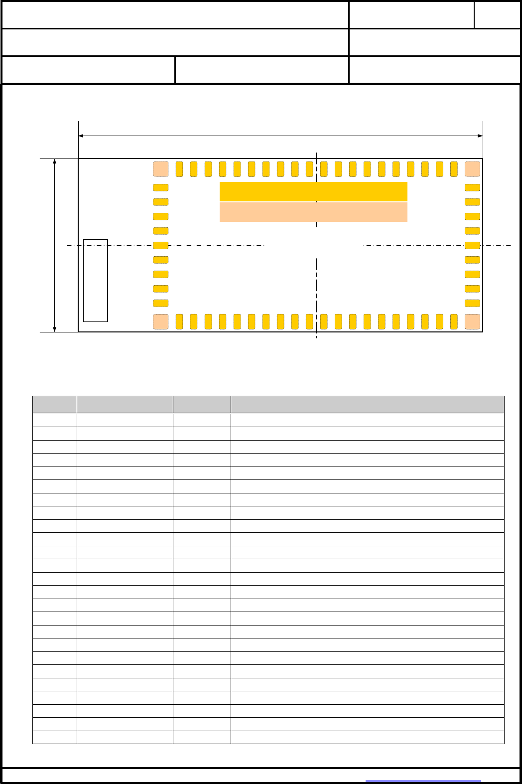
6. TERMINAL LAYOUT
Antenna
35.0 mm
15.0 mm
Height
3.8 mm
Top View
22
32
Pad 1 = 4 x 1.30mm x 1.30mm
Pad 2 = 58 x 0.60mm x 1.30mm
1
53
Please refer also to the MC1321x technical data sheet and reference manual, which is given in
[2] and [3] in the chapter “Related Documents”.
Pin No.
Pin
Pin Type
Description
1
GND
I/O
Ground
2
PTD4 / TPM2CH1
Dig. I/O
MCU Port D Bit 4 / TPM2 Channel 1
3
PTD5 / TPM2CH2
Dig. I/O
MCU Port D Bit 5 / TPM2 Channel 2
4
PTD6 / TPM2CH3
Dig. I/O
MCU Port D Bit 6 / TPM2 Channel 3
5
PTD7 / TPM2CH4
Dig. I/O
MCU Port D Bit 7 / TPM2 Channel 4
6
PTD2 / TPM1CH2
Dig. I/O
MCU Port D Bit 2 / TPM1 Channel 2
7
NC
Not connected – leave open
8
PTC0 / TXD2
Dig. I/O
MCU Port C Bit 0 / SCI2 TX data out (UART2)
9
PTC1 / RXD2
Dig. I/O
MCU Port C Bit 1 / SCI2 RX data in (UART2)
10
PTC2 / SDA1
Dig. I/O
MCU Port C Bit 1/ IIC bus data (I²C)
11
PTC3 / SCL1
Dig. I/O
MCU Port C Bit 1/ IIC bus clock (I²C)
12
PTB0 / AD1P0
I/O
MCU Port B Bit 0 / ATD analog Channel 0
13
PTB1 / AD1P1
I/O
MCU Port B Bit 1 / ATD analog Channel 1
14
PTB2 / AD1P2
I/O
MCU Port B Bit 2 / ATD analog Channel 2
15
PTB3 / AD1P3
I/O
MCU Port B Bit 3 / ATD analog Channel 3
16
PTB4 / AD1P4
I/O
MCU Port B Bit 4 / ATD analog Channel 4
17
PTB5 / AD1P5
I/O
MCU Port B Bit 5 / ATD analog Channel 5
18
PTB6 / AD1P6
I/O
MCU Port B Bit 6 / ATD analog Channel 6
19
PTB7 / AD1P7
I/O
MCU Port B Bit 7 / ATD analog Channel 7
20
VREFH
I
MCU high reference voltage for ATD
21
VREFL
I
MCU low reference voltage for ATD
22
GND
I/O
Ground
23
Vcc
Power I
Modem voltage regulators’ input
24
Vcc
Power I
Modem voltage regulators’ input
25
PTG1 / XTAL
Dig. I/O / O
MCU Port G Bit 1 / Crystal oscillator output P
(2)
P

CLASSIFICATION
PRODUCT SPECIFICATION
No.
DS-4561-2400-102
REV.
I
SUBJECT
MODEM FOR 802.15.4 IEEE STANDARD
PAGE
8 of 34
CUSTOMER’S CODE
PAN4561H /M /L
PANASONIC PART NUMBER
ENWC9A22xxEF / .25xx. / .21xx.
DATE
28.01.2014
PANASONIC INDUSTRIAL DEVICES EUROPE GMBH
www.pideu.pansonic.de
PRELIMINARY
Pin No.
Pin
Pin Type
Description
26
PTG2 / EXTAL
Dig. I/O / I
MCU Port G Bit 2 / Crystal oscillator input P
(2)
P (3).(4)
27
RESET
Dig. I
MCU reset. Active low
28
CLKO
Dig. O
Programmable Clock Output (default: 32,768 kHz)P (3)
29
GPIO2
Dig. I/O
GPIO2 from RF transceiver unit
30
PTG0 / BKGND / MS
Dig. I/O
MCU Port G Bit 0 / Background / Mode Select P
(1)
P
31
GPIO1
Dig. I/O
GPIO1 from RF transceiver unit
32
GND
I/O
Ground
33
VDDA
Power O
Modem analog regulated supply output - leave open
34
PTA7 / KBI1P7
Dig. I/O
MCU Port A Bit 7 / Keyboard Input Bit 7
35
PTA6 / KBI1P6
Dig. I/O
MCU Port A Bit 6 / Keyboard Input Bit 6
36
PTA5 / KBI1P5
Dig. I/O
MCU Port A Bit 5 / Keyboard Input Bit 5
37
PTA4 / KBI1P4
Dig. I/O
MCU Port A Bit 4 / Keyboard Input Bit 4
38
PTA3 / KBI1P3
Dig. I/O
MCU Port A Bit 3 / Keyboard Input Bit 3
39
PTA2 / KBI1P2
Dig. I/O
MCU Port A Bit 2 / Keyboard Input Bit 2
40
PTA1 / KBI1P1
Dig. I/O
MCU Port A Bit 1 / Keyboard Input Bit 1
41
PTA0 / KBI1P0
Dig. I/O
MCU Port A Bit 0 / Keyboard Input Bit 0
42
PTC7 / GPIO
Dig. I/O
MCU Port C Bit 7 (GPIO)
43
PTC6 / GPIO
Dig. I/O
MCU Port C Bit 6 (GPIO)
44
PTC5 / GPIO
Dig. I/O
MCU Port C Bit 5 (GPIO)
45
PTC4 / GPIO
Dig. I/O
MCU Port C Bit 4 (GPIO)
46
PTE0 / TXD1
Dig. I/O
MCU Port E Bit 0 / SCI1 TX data out (UART1)
47
PTE1 / RXD1
Dig. I/O
MCU Port E Bit 1/ SCI1 RX data in (UART1)
48
GPIO5
Dig. I/O
GPIO5 from RF transceiver unit
49
GPIO6
Dig. I/O
GPIO6 from RF transceiver unit
50
GPIO7
Dig. I/O
GPIO7 from RF transceiver unit
51
NC
Not connected – leave open
52
NC
Not connected – leave open
53 - 54
GND
I/O
Ground
55
EXANT
I/O
Pin for external antenna (50 )
56 - 62
GND
I/O
Ground
Note:
(1) PTG0 is output only. Pin is I/O when used as BDM function.
(2) Full I/O when not used as clock source. Please refer also to [2].
(3) CLKO (Pin 28) and PTG2/EXTAL (Pin 26) must be connected when the programmable clock derived
from the internal 16 MHz crystal.
Do not connect when the clock derived from Internal Reference Generator in MC13213.
(4) PTG2 / EXTAL is not accessible with E-Senza software
Port PTA, PTB, PTC, PTD, PTE, PTG have internal software controlled pull-up resistors. For detailed
information refer to [3].
All I/O pins of port PTC are high current pins. The maximum current for all pins together must not exceed
60mA. A continuous current of 7mA, and 25mA burst for each port pin must not be exceeded. For detailed
information refer to [3].
CLASSIFICATION
PRODUCT SPECIFICATION
No.
DS-4561-2400-102
REV.
I
SUBJECT
MODEM FOR 802.15.4 IEEE STANDARD
PAGE
9 of 34
CUSTOMER’S CODE
PAN4561H /M /L
PANASONIC PART NUMBER
ENWC9A22xxEF / .25xx. / .21xx.
DATE
28.01.2014
PANASONIC INDUSTRIAL DEVICES EUROPE GMBH
www.pideu.pansonic.de
PRELIMINARY
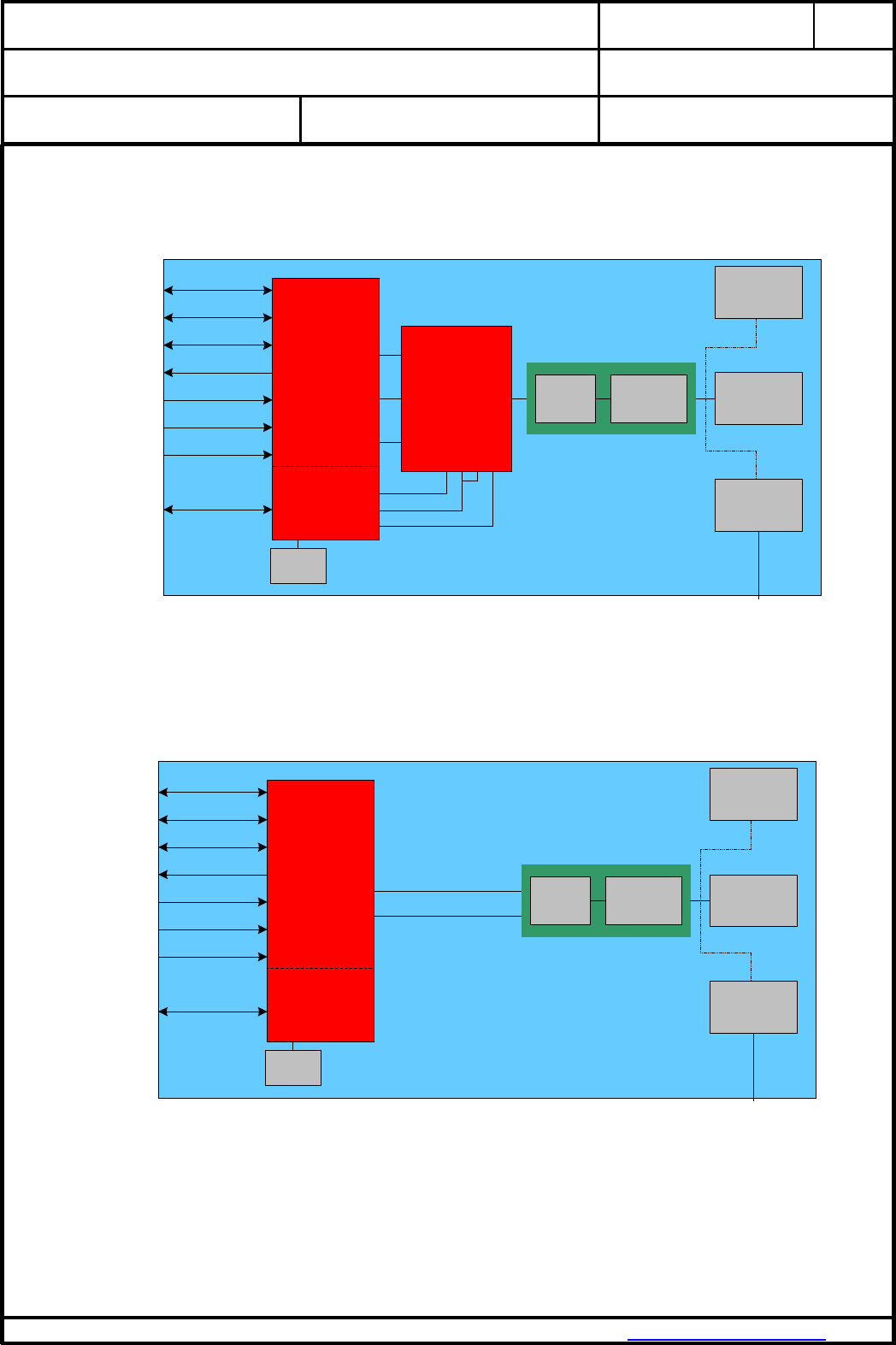
7. BLOCK DIAGRAM
PAN4561H / PAN4561M
Crystal
16 MHz
serial
communication
Rx / Tx
Matching
BP-
Filter
Bottom
Pad
Hirose
Plug
Ceramic
Antenna
Timer/PWM
A/D
BKGD
SCI1 & 2
Port A ... E, G
Logic IOs
Actuators
Sensors
Reset
Wake Up
Programming
EXANT
PIN55
MC13213
RF
Transceiver
& µC
GPIO4
LNA H/L gain
PA/LNA Enable
GPIO3
RF Transceiver
CC2591-
CC2590
RF Frontend
(LNA & PA)
PAEN
EN
HGM
RF transceiver
GPIOs GPIO1,2,5,6,7
CT_Bias
RXTX
RX/TX
The RF frontend IC CC2591 / CC2590 is controlled with GPIO3, GPIO4 and CT_Bias from RF
transceiver unit (see above block diagram).
PAN4561L
Crystal
16 MHz
serial
communication
Rx / Tx
Matching
Balun
Bottom
Pad
Hirose
Plug
Ceramic
Antenna
Timer/PWM
A/D
BKGD
SCI1 & 2
Port A ... E, G
Logic IOs
Actuators
Sensors
Reset
Wake Up
Programming
EXANT
PIN55
MC13213
RF
Transceiver
& µC
GPIO4
GPIO3
RF Transceiver
RF transceiver
GPIOs GPIO1,2,5,6,7
CT_Bias
The MC13213 is used in single port configuration with its internal Tx/Rx switch.
For more details refer to chapter 7.1.

CLASSIFICATION
PRODUCT SPECIFICATION
No.
DS-4561-2400-102
REV.
I
SUBJECT
MODEM FOR 802.15.4 IEEE STANDARD
PAGE
10 of 34
CUSTOMER’S CODE
PAN4561H /M /L
PANASONIC PART NUMBER
ENWC9A22xxEF / .25xx. / .21xx.
DATE
28.01.2014
PANASONIC INDUSTRIAL DEVICES EUROPE GMBH
www.pideu.pansonic.de
PRELIMINARY
7.1. SOFTWARE DIFFERENCES
7.1.1. Test / Demo software
Modules with Test / Demo software are intended for customer writing their own software for
the module. The module contains software but only with a small instruction set.
The front end IC CC2591 / CC2590 is enabled and disabled with RF transceiver GPIO4.
Set high to enable and low to disable the chip. Please refer to appendix [10].
The LNA has two modes, high and low gain. This mode is controlled with RF transceiver
GPIO3. Set it high for high gain and low for low gain mode. Please refer to appendix [10].
The RXTX signal on CC2591 and CC2590 is controlled by CT_Bias pin. Please refer to
appendix [10].
7.1.2. E-Senza software
Modules with E-Senza software can be used to set up a measurement system easily with a
GUI.
With this software it is not possible to set the modules into energy saving sleep mode.
7.1.3. Synapse software
With Synapse software the customer writes his own scripts based on easy to learn, Phyton
based, programming language. This software is very flexible and can be used for multiple
applications.
The control of PA/LNA is primary supported from version SNAPv2.2.15 or newer.
The Synapse software on the module provides several initializing parameters called NV-
parameters. These are already set. For detailed information refer to SNAP Reference
Manual [9].
To comply to FCC regulation the power level has to be reduced to txPwr(14) for
PAN4561H. For detailed information on FCC compliance refer to chapter 27. Regulatory
Information.
Synapse Wireless Inc. probably releases two to three times a year a new SNAP release.
PAN4561 modules will always be shipped with the newest SNAP version.

CLASSIFICATION
PRODUCT SPECIFICATION
No.
DS-4561-2400-102
REV.
I
SUBJECT
MODEM FOR 802.15.4 IEEE STANDARD
PAGE
11 of 34
CUSTOMER’S CODE
PAN4561H /M /L
PANASONIC PART NUMBER
ENWC9A22xxEF / .25xx. / .21xx.
DATE
28.01.2014
PANASONIC INDUSTRIAL DEVICES EUROPE GMBH
www.pideu.pansonic.de
PRELIMINARY
8. KEY PARTS LIST
Part Name
Material
P.W.Board
Glass cloth epoxide resin with gold plating
Casing
Material: BZn15-20, thickness 0.15mm
IC part name
MC13213 (Freescale www.freescale.com/)
All information are based on [2] chapter 28
CC2591 / CC2590 (Texas Instruments www.ti.com)
All information are based on [10] chapter 27.
9. TEST CONDITIONS
Measurements are made under room temperature and humidity unless otherwise specified.
Temperature 25 ± 10°C Humidity 40 to 85%RH
Supply voltage 3.0V

CLASSIFICATION
PRODUCT SPECIFICATION
No.
DS-4561-2400-102
REV.
I
SUBJECT
MODEM FOR 802.15.4 IEEE STANDARD
PAGE
12 of 34
CUSTOMER’S CODE
PAN4561H /M /L
PANASONIC PART NUMBER
ENWC9A22xxEF / .25xx. / .21xx.
DATE
28.01.2014
PANASONIC INDUSTRIAL DEVICES EUROPE GMBH
www.pideu.pansonic.de
PRELIMINARY
10. ABSOLUT MAXIMUM RATINGS
The maximum ratings may not be exceeded under any circumstances (not even momentarily) as
permanent damage to the module will result.
No.
Item
Symbol
Absolute Maximum Ratings
Unit
1
Supply voltage
VBCCB
-0.3 to +3.6
Vdc
2
Ripple on VBCCB
VccBripB
tbd (2) (ripple frequency ≥200kHz)
mVpp
3
Digital input voltages
VBinB
-0.3 to VBCCB+0.3
Vdc
4
Instantaneous maximum current
Single pin limit for all digital I/O
pins P
(1)
P
IBDB
25
mAdc
5
Storage temperature range
TBstgB
-40 to +105
°C
6
Operating temperature range
TBopB
-40 to +85
°C
7
RF Input Power
PBmaxB
10
dBm
8
ESD on any pin except for pin
32 EXANT.
Human Body Model (HBM)
VBTHHBMB
2
kV
9
Moisture Sensitivity Level
MSL
3 (168 hours)
Notes:
(1) Input must be current limited to the value specified. Please refer also to [2].
(2) The supply voltage must be free of AC ripple voltage (for example from a battery or a low noise
regulator output). For noisy supply voltages, please provide a decoupling circuit (for example a ferrite
in series connection and a blocking capacitor to ground of at least 47µF directly at the module).
The exact ripple tolerance will be published in a later revision.
11. OPERATING CONDITIONS
No.
Item
Condition / Remark
Symbol
Value
Unit
Min
Typ
Max
1
Supply voltage
The typical value
is recommended
VBCCB
2.7
3.0
3.4
Vdc
2
RF Input Frequency
fBinB
2400
2483.5
MHz
3
Return loss of load at pin 55
EXANT
Receive/Transmit
Mode to 50Ω reference
load
a
-9.5
dB
4
Logic Input Voltage Low
VBILB
0
0.3xVBCCB
V
5
Logic Input Voltage High
VBIHB
0.7xVBCCB
VBCCB
V
6
SPI clock rate
The typical value is
recommended
fBSPIB
-
-
8.0
MHz
7
Operating temperature range
TBopB
-40
+85
°C
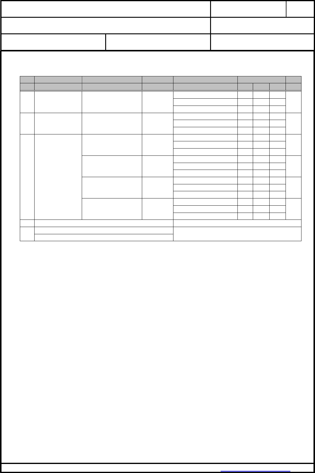
CLASSIFICATION
PRODUCT SPECIFICATION
No.
DS-4561-2400-102
REV.
I
SUBJECT
MODEM FOR 802.15.4 IEEE STANDARD
PAGE
13 of 34
CUSTOMER’S CODE
PAN4561H /M /L
PANASONIC PART NUMBER
ENWC9A22xxEF / .25xx. / .21xx.
DATE
28.01.2014
PANASONIC INDUSTRIAL DEVICES EUROPE GMBH
www.pideu.pansonic.de
PRELIMINARY
12. DC ELECTRICAL CHARACERISTICS
Assume VBCCB = 3.0V, TBambB = 25°C if nothing else stated
No.
Item
Condition / Remark
Symbol
Module type
Value
Unit
Min
Typ
Max
1
Transmit current
consumption
Transmit Mode(8)
IBCCTB
PAN4561H @ 20dBm(1)
-
200
240
mA
PAN4561M @ 10dBm
-
72
80
PAN4561L @ 0dBm
-
43
50
2
Receive current
consumption
Receive Mode(8)(8)
IBCCRB
PAN4561H
-
60
70
mA
PAN4561M
-
60
70
PAN4561L
-
60
70
3
Low power
current
consumption
Off(2)(4)(4)
IBleakageB
PAN4561H
-
0.55
‘-
µA
PAN4561M
-
0.55
‘-
PAN4561L
-
0.55
‘-
Sleep(2)(5)(9)
IBCCHB
PAN4561H
-
2.2
‘-
µA
PAN4561M
-
2.2
‘-
PAN4561L
-
2.2
‘-
Standby(2)(3)(6)(9)
IBCCDB
PAN4561H
-
36,3
‘-
µA
PAN4561M
-
36,3
‘-
PAN4561L
-
36,3
‘-
Idle(7)(7)
IBCCIB
PAN4561H
-
1.6
‘-
mA
PAN4561M
-
1.6
‘-
PAN4561L
-
1.6
‘-
4
digital I/O pin characteristics
Please refer to [2] 6.3.1 MCU DC Characteristics
6
Low voltage warning/detection
Please refer to [2] 6.3.1 MCU DC Characteristics
Power on reset re-arm voltage
Notes:
(1) SPI Register 12 has a value of 0xDC which sets output power to nominal value.
(2) To attain specified low power current, all GPIOs and other digital IO must be handled properly.
Set all port pins as output low when left open or as input when connected to defined level.
Detailed descriptions can be found at [2] at section 7.2 Low Power Considerations.
(3) CLKO frequency is set to a default value of 32.786 kHz.
(4) Off mode: Stop1 on µC, Modem off [3]. Wakeup by IRQ or Reset
(5) Sleep mode: Stop2 + RTC on µC, Modem Hibernate [3]. Wakeup by IRQ, Reset or Real-Time-
Interrupt
(6) Standby mode: Stop3 + RTC on µC, Modem Doze [3]. Wakeup by IRQ, Reset, RTI or Keyboard
Interrupt
(7) Idle mode: µC runs at reduced 2 MHz clock, Modem is in Idle state [3]
(8) µC runs in full speed mode (16 MHz clock)
(9) RTC requires external 32 kHz crystal. Without RTC 300nA less current
CLASSIFICATION
PRODUCT SPECIFICATION
No.
DS-4561-2400-102
REV.
I
SUBJECT
MODEM FOR 802.15.4 IEEE STANDARD
PAGE
14 of 34
CUSTOMER’S CODE
PAN4561H /M /L
PANASONIC PART NUMBER
ENWC9A22xxEF / .25xx. / .21xx.
DATE
28.01.2014
PANASONIC INDUSTRIAL DEVICES EUROPE GMBH
www.pideu.pansonic.de
PRELIMINARY
13. A/D CONVERTER CHARACTERISTICS
No
Item
Remark
1
ATD characteristics
Please refer to [2] 6.3.3 MCU ATD Characteristics
2
ATD timing/performance
characteristics
Please refer to [2] 6.3.3 MCU ATD Characteristics
The A/D high reference voltage VREFH is connected to pin 20 (VREFH). Connect this signal
primarily to Vcc.
The A/D low reference voltage VREFL is connected to pin 21 (VREFL). Connect this signal
primarily to GND
14. AC ELECTRICAL CHARACTERISTICS
VBCC B= 3.0V, TBambB = 25°C, 50 load at EXANT, for all channel numbers 11,12,..., 26 according to [1]
No
Receiver
Module type
Limit
Unit
Min
Typ
Max
1
Sensitivity for 1% Packet Error Rate (PER),
-85dBm required by [1]
PAN4561H
-85
-102
-105
dBm
PAN4561M
-85
-102
-105
PAN4561L
-85
-92
-
2
Saturation (maximum input level)
All
-
10
-
dBm
3
Adjacent Channel Interference for 1% PER
All
-
29
-
dB
(5MHz; desired signal -82dBm)
4
Alternate Channel Interference for 1% PER
All
-
40
-
dB
(10MHz; desired signal -82dBm)
5
Frequency Error Tolerance
All
-
-
200
kHz
6
Symbol Rate Error Tolerance
All
-
80
ppm
8
Spurious Emissions <1GHz
All
-
-
-57
dBm
9
Spurious Emissions >1GHz
All
-
-
-47
dBm
CLASSIFICATION
PRODUCT SPECIFICATION
No.
DS-4561-2400-102
REV.
I
SUBJECT
MODEM FOR 802.15.4 IEEE STANDARD
PAGE
15 of 34
CUSTOMER’S CODE
PAN4561H /M /L
PANASONIC PART NUMBER
ENWC9A22xxEF / .25xx. / .21xx.
DATE
28.01.2014
PANASONIC INDUSTRIAL DEVICES EUROPE GMBH
www.pideu.pansonic.de
PRELIMINARY
No
Transmitter
Module type
Limit
Unit
Min
Typ
Max
1
Maximum Output Power (1)
PAN4561H
-
20(3)
22(3)
dBm
PAN4561M
-
10
-
PAN4561L
-
0
-
2
Nominal Output Power (2)
PAN4561H
-
18.5
-
dBm
PAN4561M
-
9.5
-
PAN4561L
-
0
-
3
Error Vector Magnitude (EVM)
-
25
35
%
4
Power Control Range
-
30
-
dB
5
Over the Air Data Rate
-
250
-
kbps
6
2P
nd
P harmonic @ maximum output power
-
-45
-35
dBm
7
3P
rd
P harmonic @ maximum output power
-
-45
-35
dBm
8
Spurious Emissions <1GHz
-
< -40
-36
dBm
9
Spurious Emissions >1GHz
-
< -40
-30
dBm
No
Stand By
Limit
Unit
Min
Typ
Max
1
Spurious Emissions <1GHz
-
< -60
-57
dBm
2
Spurious Emissions >1GHz
-
< -50
-47
dBm
Notes:
(1) SPI Register 12 programmed to 0xFF which sets output power to maximum.
Measured at pin EXANT for the SMD pad version.
(2) SPI Register 12 programmed to 0xDC which sets output power to nominal value (maximum
allowed value to comply with FCC regulation).
Measured at pin EXANT for the SMD pad version.
(3) You have to follow your own national regulation, please check before finalizing the max. output
power by setting the right register value.
CLASSIFICATION
PRODUCT SPECIFICATION
No.
DS-4561-2400-102
REV.
I
SUBJECT
MODEM FOR 802.15.4 IEEE STANDARD
PAGE
16 of 34
CUSTOMER’S CODE
PAN4561H /M /L
PANASONIC PART NUMBER
ENWC9A22xxEF / .25xx. / .21xx.
DATE
28.01.2014
PANASONIC INDUSTRIAL DEVICES EUROPE GMBH
www.pideu.pansonic.de
PRELIMINARY
15. SOLDERING TEMPERATURE - TIME PROFILE (FOR REFLOW SOLDERING)
15.1. FOR LEAD SOLDER
Recommended temp. profile
for reflow soldering
Temp.[°C]
Time [s]
235°C max.
220 5°C
200°C
150 10°C
90 30s
10 1s
30 +20/-10s
15.2. FOR LEAD FREE SOLDER
Our used temp. profile
for reflow soldering
Temp.[°C]
Time [s]
230°C -250°C max.
220°C
150°C – 190°C
90 30s
30 +20/-10s
Reflow permissible cycles: 2
Opposite side reflow is prohibited due to the module weight.
CLASSIFICATION
PRODUCT SPECIFICATION
No.
DS-4561-2400-102
REV.
I
SUBJECT
MODEM FOR 802.15.4 IEEE STANDARD
PAGE
17 of 34
CUSTOMER’S CODE
PAN4561H /M /L
PANASONIC PART NUMBER
ENWC9A22xxEF / .25xx. / .21xx.
DATE
28.01.2014
PANASONIC INDUSTRIAL DEVICES EUROPE GMBH
www.pideu.pansonic.de
PRELIMINARY
16. MODULE DIMENSIONS
No.
Item
Dimension
Tolerance
Remark
1
Width
15.00
0.25
2
Lenght
35.00
0.25
3
Height
3.80
0.25
With case
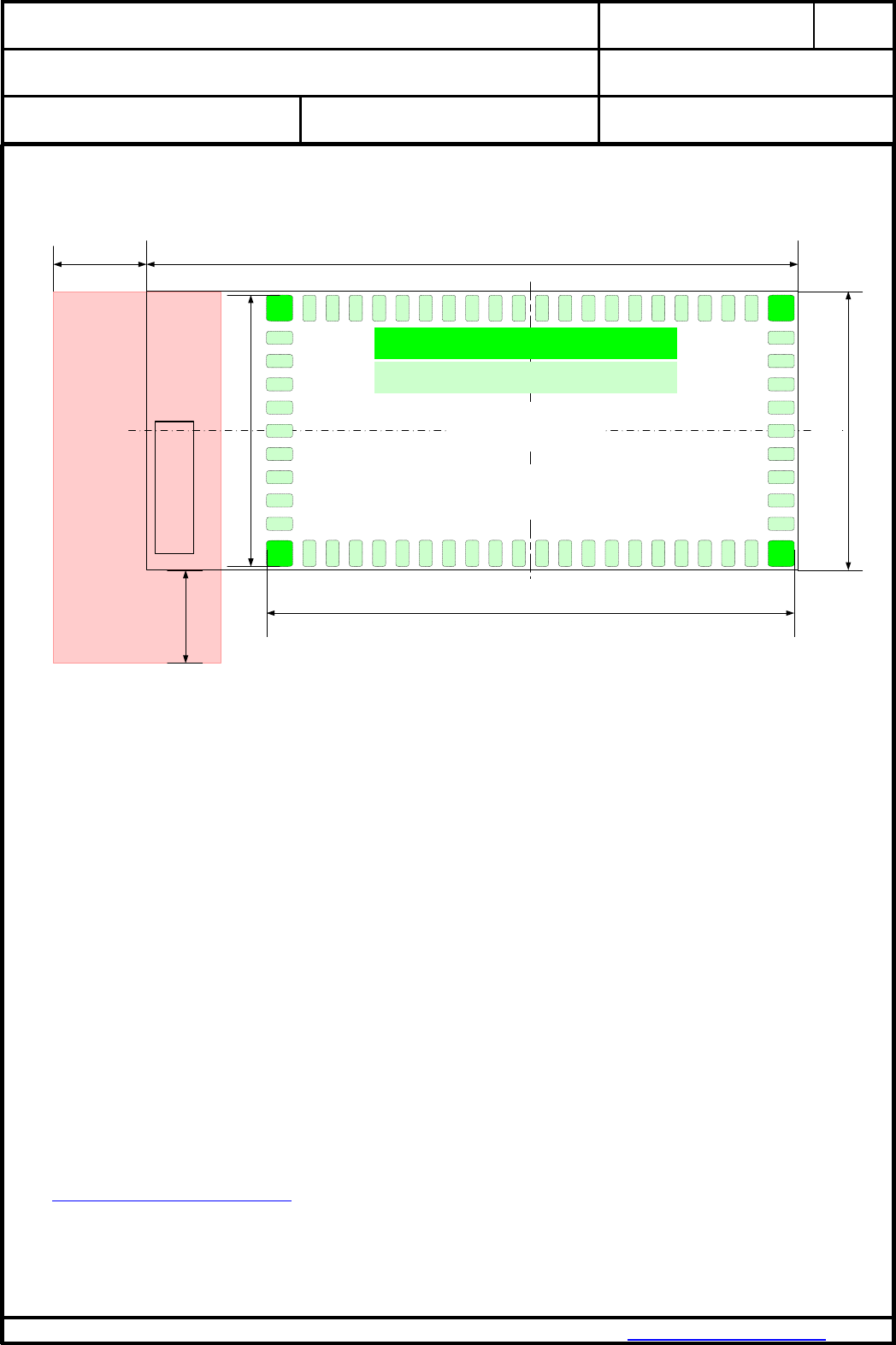
17. FOOTPRINT OF THE MODULE
0.25
0.25
1.55
2.20
2.80
3.45 14.75
15.00 mm
1.55
2.20
2.80
3.45
28.50
35.00 mm
Antenna
Top View
22
32
1
53
Pad 1 = 4 x 1.30mm x 1.30mm
Pad 2 = 58 x 0.60mm x 1.30mm
All dimensions are in millimeters.
The outer dimensions have a tolerance of 0.25mm.
CLASSIFICATION
PRODUCT SPECIFICATION
No.
DS-4561-2400-102
REV.
I
SUBJECT
MODEM FOR 802.15.4 IEEE STANDARD
PAGE
18 of 34
CUSTOMER’S CODE
PAN4561H /M /L
PANASONIC PART NUMBER
ENWC9A22xxEF / .25xx. / .21xx.
DATE
28.01.2014
PANASONIC INDUSTRIAL DEVICES EUROPE GMBH
www.pideu.pansonic.de
PRELIMINARY
18. LASER MARKING
Antenna
35.0 mm
15.0 mm
22
3253
1
ENWC9A2xxxEF
PAN4561v ES
yy Serial-No.
zz Date-code
FCC ID: T7V4561HM
The 2D-Barcode contains the following information separated by a semicolon:
Value
Description
Date-code
Date code in the format Year-Month-Day [YYMMDD]
Serial-No.
Serial number [7 signs, here 0000000]
ENWC9A2xxxEF
Ordering number [8 signs; without ENW and F, please refer also to chapter 24]
v
Module type: H, M or L (for High, Mid and Low power)
yy
The identifier for the hardware release [2 signs, here yy]
zz
The identifier for the software release [2 signs, here zz]
The point on the marking (below left) is the identifier for pin 1 of the module.
19. MECHANICAL REQUIREMENTS
No.
Item
Limit
Condition
1
Solderability
More than 75% of the soldering area shall be
coated by solder
Reflow soldering with
recommendable temperature
profile
CLASSIFICATION
PRODUCT SPECIFICATION
No.
DS-4561-2400-102
REV.
I
SUBJECT
MODEM FOR 802.15.4 IEEE STANDARD
PAGE
19 of 34
CUSTOMER’S CODE
PAN4561H /M /L
PANASONIC PART NUMBER
ENWC9A22xxEF / .25xx. / .21xx.
DATE
28.01.2014
PANASONIC INDUSTRIAL DEVICES EUROPE GMBH
www.pideu.pansonic.de
PRELIMINARY
20. RECOMMENDED LAND PATTERN
Antenna
35.0 mm
15.0 mm
Top View
22
32
Pad 1 = 4 x 1.40mm x 1.40mm
Pad 2 = 58 x 0.70mm x 1.40mm
1
53
14.6
28.35
When using the ceramic antenna, this minimum
area is restricted, means no ground, no line and in
general no metal, e.g. screws
min. 5.0
min. 5.0
In comparison to the module, we recommend
to use 50µm bigger pad size to each direction!
Dimensions in millimeters.
The land pattern dimensions above are meant to serve only as a guid. This information is
provided without any legal liability.
For the footprint, it is recommended to incorporate a 50µm bigger size for the pads in each
direction compared to the module footprint. Please refer to chapter 17. Foot Print of the Module.
For the solder paste screen, please use the same screen for the module. Solder paste screen
cutouts (with slightly different dimensions) might be optimum depending on your soldering
process For example, the chosen solder paste screen thickness might havean effect. The solder
screen thickness depends on your production standard. We recommend 120µm to 150µm.
IMPORTANT:
Although the bottom side of PAN4561 is fully coated, no copper such as through hole vias,
planes or tracks on the board component layer should be located below the PAN4561 to avoid
creating a short. In cases where a track or through hole via has to be located under the module,
please make a note that it has to be kept away from PAN4561 bottom pads. The PAN4561
multilayer pcb contains an inner RF shielding plane, therefore no pcb shielding plane below the
module is needed.
When using the antenna pad version, place the antenna on the edge of your carrier board (if
allowable).
If you have any questions on these points, please contact your local Panasonic representative.
Before releasing the layout, we recommend to sent the schematic and layout for final check to
wireless@eu.panasonic.com.

CLASSIFICATION
PRODUCT SPECIFICATION
No.
DS-4561-2400-102
REV.
I
SUBJECT
MODEM FOR 802.15.4 IEEE STANDARD
PAGE
20 of 34
CUSTOMER’S CODE
PAN4561H /M /L
PANASONIC PART NUMBER
ENWC9A22xxEF / .25xx. / .21xx.
DATE
28.01.2014
PANASONIC INDUSTRIAL DEVICES EUROPE GMBH
www.pideu.pansonic.de
PRELIMINARY
21. RELIABILITY TESTS
The measurement should be done after being exposed to room temperature and humidity for 1
hour.
Die Messungen sollten erst nach einer Stunde Lagerung unter normalen Bedingungen erfolgen.
No.
Item
Limit
Condition
1
Vibration test
Electrical parameter should be
in specification
a) Freq.:10~50Hz,Amplitude:1.5mm
a) 20min. / cycle,1hrs. each of XYZ axis
b) Freq.:30~100Hz, 6G
b) 20min. / cycle,1hrs. each of XYZ axis
2
Shock test
the same as above
Dropped onto hard wood from height of 50cm for
3 times
3
Heat cycle test
the same as above
-40°C for 30min. and +85°C for 30min.;
each temperature 300 cycles
4
Moisture test
the same as above
+60°C, 90% RH, 300h
5
Low temp. test
the same as above
-40°C, 300h
6
High temp. test
the same as above
+85°C, 300h
22. CAUTIONS
Failure to do so may result in degrading of the product’s functions and damage to the product.
22.1. DESIGN NOTES
(1) Please follow the conditions written in this specification, especially the control
signals of this module.
(2) The supply voltage has to be free of AC ripple voltage (for example from a
battery or a low noise regulator output). For noisy supply voltages, provide a
decoupling circuit (for example a ferrite in series connection and a blocking
capacitor to ground of at least 47uF directly at the module).
(3) This product should not be mechanically stressed when installed.
(4) Heat is the major cause of shortening the life of these products. Please keep this
product away from heat.
Avoid assembly and use of the target equipment in conditions where the
products' temperature may exceed the maximum tolerance.
(5) The supply voltage should not be exceedingly high or reversed. It should not
carry noise and/or spikes.
(6) Please keep this product away from other high frequency circuits.
22.2. INSTALLATION NOTES
(1) Reflow soldering is possible twice based on the conditions in chapter 15.
Please set up the temperature at the soldering portion of this product according
to this reflow profile.
(2) Carefully position the products so that their heat will not burn into printed circuit
boards or affect the other components that are susceptible to heat.
(3) Carefully locate these products so that their temperatures will not increase due
to the effects of heat generated by neighboring components.

CLASSIFICATION
PRODUCT SPECIFICATION
No.
DS-4561-2400-102
REV.
I
SUBJECT
MODEM FOR 802.15.4 IEEE STANDARD
PAGE
21 of 34
CUSTOMER’S CODE
PAN4561H /M /L
PANASONIC PART NUMBER
ENWC9A22xxEF / .25xx. / .21xx.
DATE
28.01.2014
PANASONIC INDUSTRIAL DEVICES EUROPE GMBH
www.pideu.pansonic.de
PRELIMINARY
(4) If a vinyl-covered wire comes into contact with the products, then the cover will
melt and generate toxic gas, damaging the insulation. Never allow contact
between the cover and these products to occur.
(5) This product should not be mechanically stressed or vibrated when reflowed.
(6) If you want to repair your board by hand soldering, please keep the conditions of
this chapter.
(7) Please do not wash this product.
(8) Please refer to the recommended pattern when designing a board.
(9) Pressing on parts of the metal cover or fastening objects to the metal will cause
damage to the unit.
22.3. USAGE CONDITIONS NOTES
(1) Please take measures to protect the unit against static electricity.
If pulses or other transient loads (a large load applied in a short time) are applied
to the products, check and evaluate their operation befor assembly on the final
products.
(2) Please do not use dropped products.
(3) Please do not touch, damage or place dirt on the pins.
(4) Please follow the recommended condition ratings about the power supply
applied to this product.
(5) Electrode peeling strength: Do not add pressure of more than 4.9N when
soldered on PCB.
(6) Pressing on parts of the metal cover or fastening objects to the metal cover will
cause damage.
(7) These products are intended for general purpose and standard use in general
electronic equipment, such as home appliances, office equipment, information
and communication equipment.

CLASSIFICATION
PRODUCT SPECIFICATION
No.
DS-4561-2400-102
REV.
I
SUBJECT
MODEM FOR 802.15.4 IEEE STANDARD
PAGE
22 of 34
CUSTOMER’S CODE
PAN4561H /M /L
PANASONIC PART NUMBER
ENWC9A22xxEF / .25xx. / .21xx.
DATE
28.01.2014
PANASONIC INDUSTRIAL DEVICES EUROPE GMBH
www.pideu.pansonic.de
PRELIMINARY
22.4. STORAGE NOTES
(1) The module may not be stressed mechanically during storage.
(2) Do not store these products in the following conditions or the performance
characteristics of the product, such as RF performance will be adversely
affected:
Storage in salty air or in an environment with a high concentration of corrosive
gas, such as Cl2, H2S, NH3, SO2, or NOX
Storage in direct sunlight
Storage in an environment where the temperature may be outside the range of
5°C to 35°C range, or where the humidity may be outside the 45 to 85% range.
Storage of the products for more than one year after the date of delivery at your
company if the avoidance all the above conditions (1) to (3) have been met.
(3) Storage period: Please check the adhesive strength of the embossed tape and
soldering after 6 months of storage.
(4) Please keep this product away from water, poisonous gas and corrosive gas.
(5) This product should not be stressed or shocked when transported.
(6) Please follow the specification when stacking packed crates (max. 10).
22.5. SAFETY CAUTIONS
These specifications are intended to preserve the quality assurance of products and
individual components.
Before use, check and evaluate the operation when mounted on your products. Abide by
these specifications, without deviation when using the products. These products may short-
circuit. If electrical shocks, smoke, fire, and/or accidents involving human life are
anticipated when a short circuit occurs, then provide the following failsafe functions, as a
minimum.
(1) Ensure the safety of the whole system by installing a protection circuit and a
protection device.
(2) Ensure the safety of the whole system by installing a redundant circuit or another
system to prevent a single fault causing an unsafe status.
22.6. OTHER CAUTIONS
(1) This specification sheet is copyrighted. Please do not disclose it to a third party.
(2) Please do not use the products for other purposes than those listed.
(3) Be sure to provide an appropriate fail-safe function on your product to prevent an
additional damage that may be caused by the abnormal function or the failure of
the product.
(4) This product has not been manufactured with any ozone chemical controlled
under the Montreal Protocol.
(5) These products are not intended for other uses, other than under the special
conditions shown below. Before using these products under such special
conditions, check their performance and reliability under the said special
conditions carefully to determine whether or not they can be used in such a
manner.
In liquid, such as water, salt water, oil, alkali, or organic solvent, or in places

CLASSIFICATION
PRODUCT SPECIFICATION
No.
DS-4561-2400-102
REV.
I
SUBJECT
MODEM FOR 802.15.4 IEEE STANDARD
PAGE
23 of 34
CUSTOMER’S CODE
PAN4561H /M /L
PANASONIC PART NUMBER
ENWC9A22xxEF / .25xx. / .21xx.
DATE
28.01.2014
PANASONIC INDUSTRIAL DEVICES EUROPE GMBH
www.pideu.pansonic.de
PRELIMINARY
where liquid may splash.
In direct sunlight, outdoors, or in a dusty environment
In an environment where condensation occurs.
In an environment with a high concentration of harmful gas (e.g. salty air,
HCl, Cl2, SO2, H2S, NH3, and NOX)
(6) If an abnormal voltage is applied due to a problem occurring in other
components or circuits, replace these products with new products because they
may not be able to provide normal performance even if their electronic
characteristics and appearances appear satisfactory.
(7) When you have any question or uncertainty, both of you and Panasonic
sincerely cope with it.
CLASSIFICATION
PRODUCT SPECIFICATION
No.
DS-4561-2400-102
REV.
I
SUBJECT
MODEM FOR 802.15.4 IEEE STANDARD
PAGE
24 of 34
CUSTOMER’S CODE
PAN4561H /M /L
PANASONIC PART NUMBER
ENWC9A22xxEF / .25xx. / .21xx.
DATE
28.01.2014
PANASONIC INDUSTRIAL DEVICES EUROPE GMBH
www.pideu.pansonic.de
PRELIMINARY
23. PACKAGING
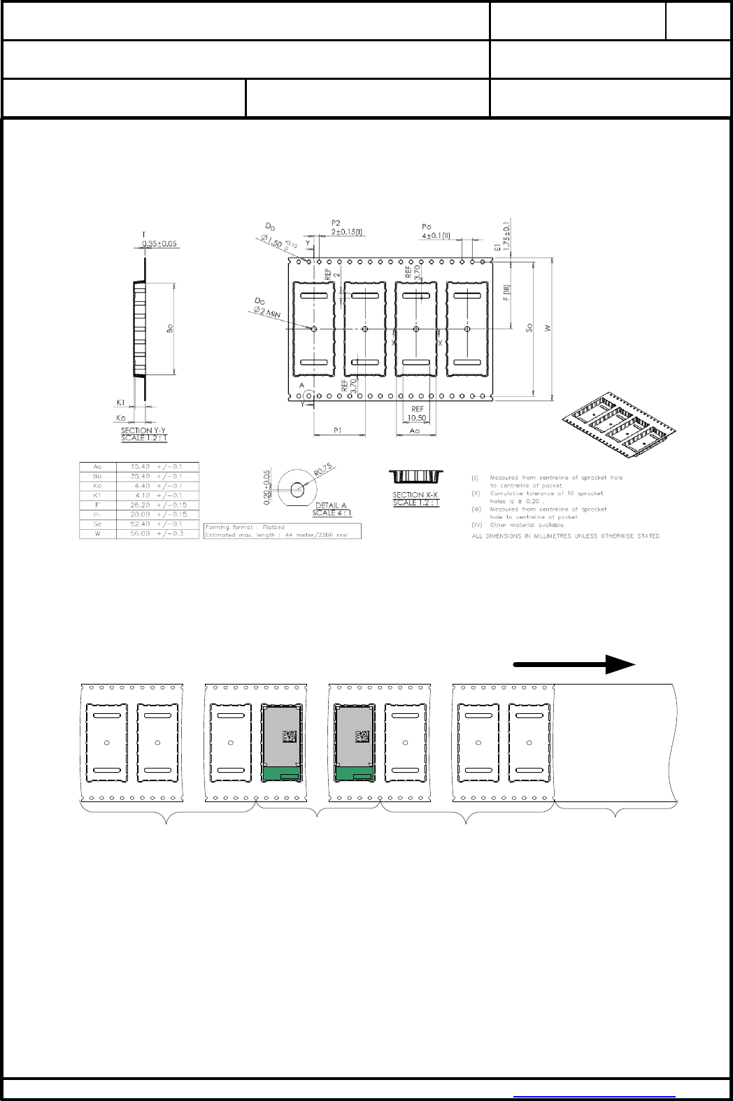
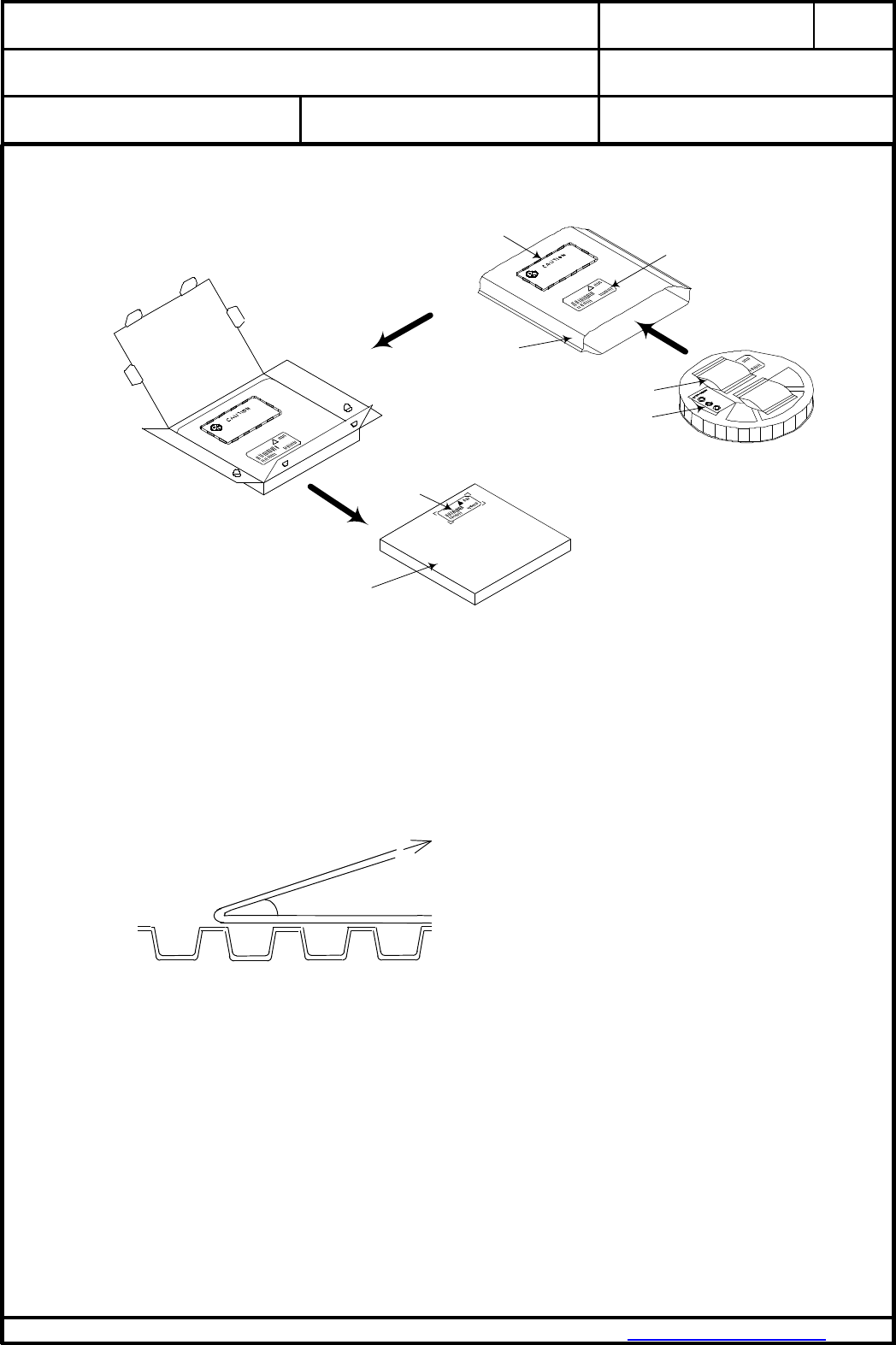
23.1. TAPE DIMENSION
23.2. PACKING IN TAPE
trailer (empty)
1 x circumference /hub
(min 160mm)
component
packed area
standard 500pcs
leader (empty)
minimum 10 pitch
Top cover tape
more than 1 x
circumference plus
100mm to avoid
fixing of tape end on
sealed modules.
Antenna
22
3253
1
Antenna
22
3253
1
Direction of unreeling (for customer)
Empty spaces in component packed area shall be less than two per reel and those spaces
shall not be consecutive.
Top cover tape shall not be found on reel holes and shall not stick out from reel.
CLASSIFICATION
PRODUCT SPECIFICATION
No.
DS-4561-2400-102
REV.
I
SUBJECT
MODEM FOR 802.15.4 IEEE STANDARD
PAGE
25 of 34
CUSTOMER’S CODE
PAN4561H /M /L
PANASONIC PART NUMBER
ENWC9A22xxEF / .25xx. / .21xx.
DATE
28.01.2014
PANASONIC INDUSTRIAL DEVICES EUROPE GMBH
www.pideu.pansonic.de
PRELIMINARY
23.3. COMPONENT DIRECTION
Antenna
1
PAN4561 ES
03 000001
05 081211
ENWC9A22A4EF
Direction of unreeling
(for customer) Pin 1 Marking
(Top Side)
Pin 1
(Bottom Side)
Please refer also to chapter 18. Labeling Drawing
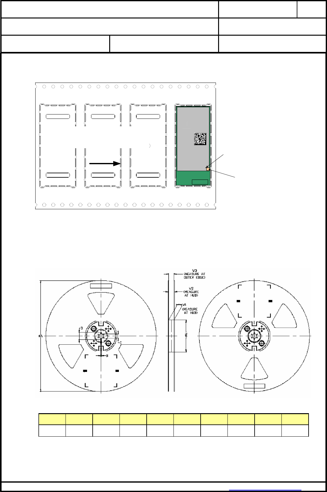
23.4. REEL DIMENSION
A BD NW2
MAX MIN MIN ±1.0 MAX
13 +0.5 25.0 +2.0 24.4 +3.0
-0.2 -0.0 -0.5
*Latch (2PC)
All dimensions in millimeters unless otherwise stated
Assembly
Method
24mm
330.0
1.5
20.2
100.0
30.4
*Latch
TAPE SIZE
C
W1
W3
CLASSIFICATION
PRODUCT SPECIFICATION
No.
DS-4561-2400-102
REV.
I
SUBJECT
MODEM FOR 802.15.4 IEEE STANDARD
PAGE
26 of 34
CUSTOMER’S CODE
PAN4561H /M /L
PANASONIC PART NUMBER
ENWC9A22xxEF / .25xx. / .21xx.
DATE
28.01.2014
PANASONIC INDUSTRIAL DEVICES EUROPE GMBH
www.pideu.pansonic.de
PRELIMINARY
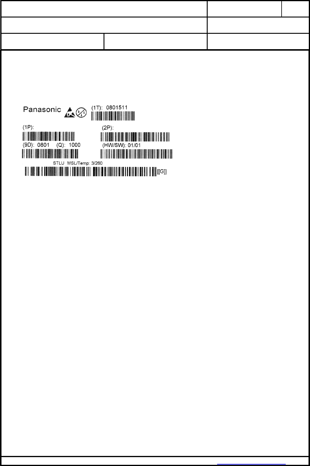
23.5. LABEL FOR PACKAGE
The label below shows only an example.
(1T): Lotcode [YYWWDLL]
YY year today 10
WW normal calendar week today 01
D day today 5 (Friday)
L line identifier, if more as one actual 1
L lot identifier per day e.g. 1, 2, 3…
(1P) Customer Order Code, if any, otherwise put company name on it.
(2P) Panasonic Part Number
(3P) Module type [PAN4561H, PAN4561M or PAN4561L]
(9D) Datecode as [2xYear, 2xMonth, 2xDay]
(Q) Quantity [XXXX], variable
(HW/SW) Hardware /Software Release identifier
[[G]] Identifier that the product is RoHS conform, please refer to chapter 25.
ENWC9A22xxEF
Customer Code
(3P):PAN4561v
CLASSIFICATION
PRODUCT SPECIFICATION
No.
DS-4561-2400-102
REV.
I
SUBJECT
MODEM FOR 802.15.4 IEEE STANDARD
PAGE
27 of 34
CUSTOMER’S CODE
PAN4561H /M /L
PANASONIC PART NUMBER
ENWC9A22xxEF / .25xx. / .21xx.
DATE
28.01.2014
PANASONIC INDUSTRIAL DEVICES EUROPE GMBH
www.pideu.pansonic.de
PRELIMINARY
23.6. TOTAL PACKING HANDLING
23.7. COVER TAPE REEL STRENGTH
Force direction
Speed = 300mm/min.
Cover tape reel strength
=0.098~0.68N (10~70g)
θ= 10deg
barcode
label
moisture-sensitive print
(already exist on barrier bag) barcode
label
desiccant 1) 2)
moisture indicator
barrier bag
sealed
inner carton box
size 340 x 340 x 41 mm³
1) quantity of desiccant according
to calculation
2) optional: desiccant placed into
the corner of the barrier bag

CLASSIFICATION
PRODUCT SPECIFICATION
No.
DS-4561-2400-102
REV.
I
SUBJECT
MODEM FOR 802.15.4 IEEE STANDARD
PAGE
28 of 34
CUSTOMER’S CODE
PAN4561H /M /L
PANASONIC PART NUMBER
ENWC9A22xxEF / .25xx. / .21xx.
DATE
28.01.2014
PANASONIC INDUSTRIAL DEVICES EUROPE GMBH
www.pideu.pansonic.de
PRELIMINARY
24. ORDERING INFORMATION
24.1. PAN4561H
No.
Ordering part number
Description
1
ENWC9A22A4EF
Engineering Sample PAN4561H
802.15.4 Mesh Network Module, which includes Ceramic Antenna,
Low Noise Amplifier, up to +20dBm Power Amplifier and 60kBit
Flash Memory.
Synapse SNAP software included, please refer also to [9].
2
ENWC9A22B4EF
Engineering Sample PAN4561H
802.15.4 Mesh Network Module, which includes UFL connector,
Low Noise Amplifier, up to +20dBm Power Amplifier and 60kBit
Flash Memory.
Synapse SNAP software included, please refer also to [9].
3
ENWC9A22C4EF
Engineering Sample PAN4561H
802.15.4 Mesh Network Module, which includes RF out on SMD
pad, Low Noise Amplifier, up to +20dBm Power Amplifier and
60kBit Flash Memory.
Synapse SNAP software included, please refer also to [9].
4
ENWC9A22A2EF
Same as number 1, but with Software:
SN55 from E-Senza, please refer also to [8]
5
ENWC9A22B2EF
Same as number 2, but with Software:
SN55 from E-Senza, please refer also to [8]
6
ENWC9A22C2EF
Same as number 3, but with Software:
SN55 from E-Senza, please refer also to [8]
7
ENWC9A22A1EF
Same as number 1, but with Freescale based SMAC test software.
8
ENWC9A22B1EF
Same as number 2, but with Freescale based SMAC test software.
9
ENWC9A22C1EF
Same as number 3, but with Freescale based SMAC test software.

CLASSIFICATION
PRODUCT SPECIFICATION
No.
DS-4561-2400-102
REV.
I
SUBJECT
MODEM FOR 802.15.4 IEEE STANDARD
PAGE
29 of 34
CUSTOMER’S CODE
PAN4561H /M /L
PANASONIC PART NUMBER
ENWC9A22xxEF / .25xx. / .21xx.
DATE
28.01.2014
PANASONIC INDUSTRIAL DEVICES EUROPE GMBH
www.pideu.pansonic.de
PRELIMINARY
24.2. PAN4561M
No.
Ordering part number
Description
1
ENWC9A25A4EF
Engineering Sample PAN4561M
802.15.4 Mesh Network Module, which includes Ceramic Antenna,
Low Noise Amplifier, up to +10dBm Power Amplifier and 60kBit
Flash Memory.
Synapse SNAP software included, please refer also to [9].
2
ENWC9A25B4EF
Engineering Sample PAN4561M
802.15.4 Mesh Network Module, which includes UFL connector,
Low Noise Amplifier, up to +10dBm Power Amplifier and 60kBit
Flash Memory.
Synapse SNAP software included, please refer also to [9].
3
ENWC9A25C4EF
Engineering Sample PAN4561M
802.15.4 Mesh Network Module, which includes RF out on SMD
pad, Low Noise Amplifier, up to +10dBm Power Amplifier and
60kBit Flash Memory.
Synapse SNAP software included, please refer also to [9].
4
ENWC9A25A2EF
Same as number 1, but with Software:
SN55 from E-Senza, please refer also to [8]
5
ENWC9A25B2EF
Same as number 2, but with Software:
SN55 from E-Senza, please refer also to [8]
6
ENWC9A25C2EF
Same as number 3, but with Software:
SN55 from E-Senza, please refer also to [8]
7
ENWC9A25A1EF
Same as number 1, but with Freescale based SMAC test software.
8
ENWC9A25B1EF
Same as number 2, but with Freescale based SMAC test software.
9
ENWC9A25C1EF
Same as number 3, but with Freescale based SMAC test software.
24.3. PAN4561L
No.
Ordering part number
Description
1
ENWC9A21A4EF
Engineering Sample PAN4561L
802.15.4 Mesh Network Module, which includes Ceramic Antenna,
up to 0dBm output power and 60kBit Flash Memory.
Synapse SNAP software included, please refer also to [9].
2
ENWC9A21B4EF
Engineering Sample PAN4561L
802.15.4 Mesh Network Module, which includes UFL connector, up
to 0dBm output power and 60kBit Flash Memory.
Synapse SNAP software included, please refer also to [9].
3
ENWC9A21C4EF
Engineering Sample PAN4561L
802.15.4 Mesh Network Module, which includes RF out on SMD
pad, up to 0dBm output power and 60kBit Flash Memory.
Synapse SNAP software included, please refer also to [9].
4
ENWC9A21A2EF
Same as number 1, but with Software:
SN55 from E-Senza, please refer also to [8]
5
ENWC9A21B2EF
Same as number 2, but with Software:
SN55 from E-Senza, please refer also to [8]
6
ENWC9A21C2EF
Same as number 3, but with Software:
SN55 from E-Senza, please refer also to [8]
7
ENWC9A21A1EF
Same as number 1, but with Freescale based SMAC test software.
8
ENWC9A21B1EF
Same as number 2, but with Freescale based SMAC test software.
9
ENWC9A21C1EF
Same as number 3, but with Freescale based SMAC test software.

CLASSIFICATION
PRODUCT SPECIFICATION
No.
DS-4561-2400-102
REV.
I
SUBJECT
MODEM FOR 802.15.4 IEEE STANDARD
PAGE
30 of 34
CUSTOMER’S CODE
PAN4561H /M /L
PANASONIC PART NUMBER
ENWC9A22xxEF / .25xx. / .21xx.
DATE
28.01.2014
PANASONIC INDUSTRIAL DEVICES EUROPE GMBH
www.pideu.pansonic.de
PRELIMINARY
25. ROHS DECLARATION
Declaration of environmental compatibility for supplied products:
Hereby we declare to our best present knowledge based on declaration of our suppliers that this
product does not contain the following substances which are banned by Directive 2002/95/EC
(RoHS) or contains a maximum concentration of 0.1% by weight in homogeneous materials for
Lead and lead compounds
Mercury and mercury compounds
Chromium (VI)
PBB (polybrominated biphenyl) category
PBDE (polybrominated biphenyl ether) category
And a maximum concentration of 0.01% by weight in homogeneous materials for
Cadmium and cadmium compounds
26. DATA SHEET STATUS
This data sheet contains data from the PRELIMINARY specification. Supplementary data will be
published at a later date. Panasonic Electronic Devices Europe GmbH reserves the right to
change the specification without notice, in order to improve the design and supply the best
possible product.
Please consult the most recently issued data sheet before initiating or completing a design.
If there is an update, please download under: PAN4561 Latest Data Sheet!
27. REGULATORY INFORMATION
27.1. FCC NOTICE
The device PAN4561, including the ceramic antenna (ENWC9A2xAxEF) and also the SMD
type (ENWC9A2xCxEF), including with the antennas, which are listed in 27.5, complies
with Part 15 of the FCC Rules. The device meets the requirements for modular transmitter
approval as detailed in FCC public Notice DA00-1407.transmitter under following
restrictions:
PAN4561H
1) Channel 26, according to [1] IEEE 802.15.4, must not be used
2) Maximum output power of 18.5dBm allowed. This level refers to the value 0xDC in SPI
register 12 of MC13213 (refer to [2] and [3]).
3) Duty cycle of 1% allowed
PAN4561M
1) Channel 26, according to [1] IEEE 802.15.4, must not be used

CLASSIFICATION
PRODUCT SPECIFICATION
No.
DS-4561-2400-102
REV.
I
SUBJECT
MODEM FOR 802.15.4 IEEE STANDARD
PAGE
31 of 34
CUSTOMER’S CODE
PAN4561H /M /L
PANASONIC PART NUMBER
ENWC9A22xxEF / .25xx. / .21xx.
DATE
28.01.2014
PANASONIC INDUSTRIAL DEVICES EUROPE GMBH
www.pideu.pansonic.de
PRELIMINARY
PAN4561L
No restrictions
Operation is subject to the following two conditions: (1) This device may not cause harmful
interference, and (2) This device must accept any interference received, including
interference that may cause undesired operation.
27.2. CAUTION
The FCC requires the user to be notified that any changes or modifications made to this
device that are not expressly approved by Panasonic Electronic Devices Europe GmbH
may void the user's authority to operate the equipment.
This equipment has been tested and found to comply with the limits for a Class B digital
device, pursuant to Part 15 of the FCC Rules. These limits are designed to provide
reasonable protection against harmful interference in a residential installation. This
equipment generates, uses and can radiate radio frequency energy and, if not installed and
used in accordance with the instructions, may cause harmful interference to radio
communications. However, there is no guarantee that interference will not occur in a
particular installation. If this equipment does cause harmful interference to radio or
television reception, which can be determined by turning the equipment off and on, the user
is encouraged to try to correct the interference by one or more of the following measures:
Reorient or relocate the receiving antenna.
Increase the separation between the equipment and receiver.
Connect the equipment into an outlet on a circuit different from that to which the
receiver is connected.
Consult the dealer or an experienced radio/TV technician for help
27.3. LABELING REQUIREMENTS
The Original Equipment Manufacturer (OEM) must ensure that FCC labeling requirements
are met. This includes a clearly visible label (laser marking) on the outside of the OEM
enclosure specifying the appropriate Panasonic FCC identifier for this product as well as
the FCC Notice above. The FCC identifier is FCC ID: T7V4561HM.
In any case end product must be labelled exterior with "Contains FCC ID: T7V4561HM"
27.4. ANTENNA WARNING
The related part number for this device is ENWC9A2xBxEF (PAN4561 with U.FL
connector) and ENWC9A2xCxEF (PAN4561 with SMD pad). For details, please see the
chapter 24. Ordering Information. This device is tested with a standard SMA connector and
with the antennas listed below. When integrated in the OEMs product, these fixed antennas
require installation preventing end-users from replacing them with non-approved antennas.
Any antenna not in the following table must be tested to comply with FCC Section 15.203
for unique antenna connectors and Section 15.247 for emissions. The FCC identifier for
this device with the antenna listed in item 1 are the same (FCC ID: T7V4561HM).

CLASSIFICATION
PRODUCT SPECIFICATION
No.
DS-4561-2400-102
REV.
I
SUBJECT
MODEM FOR 802.15.4 IEEE STANDARD
PAGE
32 of 34
CUSTOMER’S CODE
PAN4561H /M /L
PANASONIC PART NUMBER
ENWC9A22xxEF / .25xx. / .21xx.
DATE
28.01.2014
PANASONIC INDUSTRIAL DEVICES EUROPE GMBH
www.pideu.pansonic.de
PRELIMINARY
27.5. APPROVED ANTENNA LIST
Note: We are able to qualify your antenna and will add to this list as that process is completed.
Item
Part Number
Manufacturer
Frequency Band
Type
Gain (dBi)
1
2
27.6. RF EXPOSURE PAN4561
To comply with FCC RF Exposure requirements, the Original Equipment Manufacturer
(OEM) must ensure that the approved antenna in the previous table must be installed.
The preceding statement must be included as a CAUTION statement in manuals for
products operating with the approved antennas in the previous table to alert users on FCC
RF Exposure compliance.
Any notification to the end user of installation or removal instructions about the integrated
radio module is not allowed.
The radiated output power of PAN4561 with mounted ceramic antenna
(FCC ID: T7V4561HM) is below the FCC radio frequency exposure limits. Nevertheless,
the PAN4561 shall be used in such a manner that the potential for human contact during
normal operation is minimized.
End users may not be provided with the module installation instructions. OEM integrators
and end users must be provided with transmitter operating conditions for satisfying RF
exposure compliance.

CLASSIFICATION
PRODUCT SPECIFICATION
No.
DS-4561-2400-102
REV.
I
SUBJECT
MODEM FOR 802.15.4 IEEE STANDARD
PAGE
33 of 34
CUSTOMER’S CODE
PAN4561H /M /L
PANASONIC PART NUMBER
ENWC9A22xxEF / .25xx. / .21xx.
DATE
28.01.2014
PANASONIC INDUSTRIAL DEVICES EUROPE GMBH
www.pideu.pansonic.de
PRELIMINARY
28. RELATED DOCUMENTS
For an update, please search in the suitable homepage.
[1] IEEE Standard 802.15.4 –2003 Wireless Medium Access Control (MAC) and Physical
Layer (PHY) Specifications for Low-Rate Wireless Personal Area Networks (LR-WPANs)
[2] Technical Data MC1321x Document Number: MC1321x
Rev. 1.1, 03/2007 Freescale Semiconductor
[3] MC1321x Reference Manual Document Number: MC1321xRM
Rev. 1.1, 10/2006 Freescale Semiconductor
[4] Handling MAC Address erasure, AN2825, Rev. 0.0 10/2004, Freescale Semiconductor
[5] 802154MPSUG 802.15.4 MAC/PHY Software User´s Guide, Rev 1.1, Freescale
Semiconductor
[6] 802154EBRM.pdf
802.15.4 Embedded Bootloader Reference Manual Rev. 0.0 09/2004
[7] AN2771 802.15.4 PHY Protocol Test Client (PTC) Rev. 0.0 Freescale Semiconductor
[8] Manual to the E-Senza SN55 Programmer Interface Manual [Download]
[9] Manual to the Evaluation Kit from Synapse, which fits to module hardware from Panasonic
[Downloads: SNAP Reference Manual Updated 10/2/2008; SNAP Hardware Technical
Manual Updated 10/2/2008]
Each new release from Synapse, will be posted here. Be sure to be registered free under
http://forums.synapse-wireless.com.
[10] Technical Data CC2591 (2.4-GHz RF Front End) from Texas Instruments
CC2591 2.4 GHz RF Front End (Rev. A; 10. Juni 2008)
[11] Question and Answer Sheet for CC2590 and CC2591
CC2590 and CC2591 Q&A Sheet (Rev. D; 26. January 2010)

CLASSIFICATION
PRODUCT SPECIFICATION
No.
DS-4561-2400-102
REV.
I
SUBJECT
MODEM FOR 802.15.4 IEEE STANDARD
PAGE
34 of 34
CUSTOMER’S CODE
PAN4561H /M /L
PANASONIC PART NUMBER
ENWC9A22xxEF / .25xx. / .21xx.
DATE
28.01.2014
PANASONIC INDUSTRIAL DEVICES EUROPE GMBH
www.pideu.pansonic.de
PRELIMINARY
29. GENERAL INFORMATION
© Panasonic Electronic Devices Europe GmbH 2009.
All rights reserved.
This product description does not claim to be complete and free of mistakes.
Please contact the related product manager with any errata inquries.
If we deliver samples to the customer, these samples have the status Engineering Samples.
This means, the design of this product is not yet completed. Engineering Samples may be
partially or fully functional, and there may be differences published in the Data Sheet.
Engineering Samples are not qualified and are not to be used for reliability testing or series
production.
UDisclaimer:
Customer acknowledges that samples may deviate from the Data Sheet and may bear defects
due to their status of development and the lack of qualification mentioned above.
Panasonic Electronic Devices Europe GmbH disclaims any liability or product warranty for
Engineering Samples. In particular, Panasonic Electronic Devices Europe GmbH disclaims
liability for damages caused by
the use of the Engineering Sample other than for Evaluation Purposes, particularly the
installation or integration in an other product to be sold by Customer,
deviation or lapse in function of Engineering Sample,
improper use of Engineering Samples.
Panasonic Electronic Devices Europe GmbH disclaimes any liability for consequential and
incidental damages. In case of any questions, please contact your local sales partner or the
related product manager.
30. LIFE SUPPORT POLICY
This Panasonic Electronic Devices Europe GmbH product is not designed for use in life
support appliances, devices, or systems where malfunction can reasonably be expected to
result in a significant personal injury to the user, or as a critical component in any life support
device or system whose failure to perform can be reasonably expected to cause the failure of
the life support device or system, or to affect its safety or effectiveness. Customers using or
selling these products for use in such applications do so at their own risk and agree to fully
indemnify Panasonic Electronic Devices Europe GmbH for any damages resulting.