Panasonic Devices Europe PAN4555 ZigBeeTM-Module PAN4555 User Manual 1
Panasonic Industrial Devices Europe GmbH ZigBeeTM-Module PAN4555 1
UserManual.wiki
>
Panasonic Devices Europe
>
PAN4555 User Manual
Manual
Navigation menu
Upload a User Manual
Namespaces
Wiki Guide
HTML
PDF
Info
Views
User Manual
Discussion / Help
Navigation
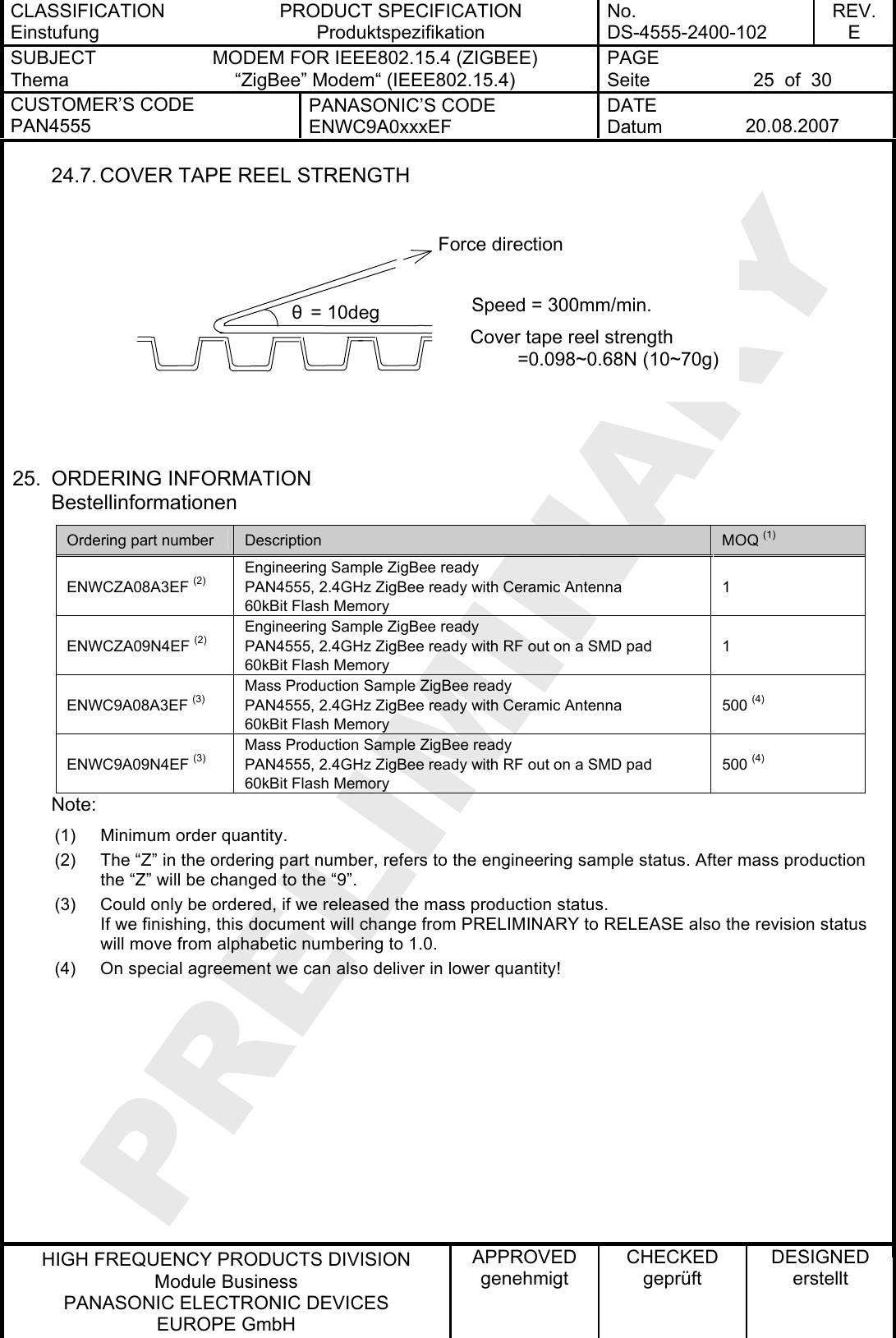
![CLASSIFICATION Einstufung PRODUCT SPECIFICATION Produktspezifikation No. DS-4555-2400-102 REV. E SUBJECT Thema MODEM FOR IEEE802.15.4 (ZIGBEE) “ZigBee” Modem“ (IEEE802.15.4) PAGE Seite 6 of 30 CUSTOMER’S CODE PAN4555 PANASONIC’S CODE ENWC9A0xxxEF DATE Datum 20.08.2007 HIGH FREQUENCY PRODUCTS DIVISION Module Business PANASONIC ELECTRONIC DEVICES EUROPE GmbH APPROVED genehmigt CHECKED geprüft DESIGNED erstellt 6. TERMINAL LAYOUT Anschlußbelegung Please refer also to the MC1321x technical data sheet and reference manual, which is given in [2] and [3] in chapter Related Documents. 12.2 mmPin No. Pin Name Pin Type Description 1 GND I/O Ground 2 PTB0 / AD1P0 I/O MCU Port B Bit 0 / ATD analog Channel 0 3 PTB1 / AD1P1 I/O MCU Port B Bit 1 / ATD analog Channel 1 4 PTB2 / AD1P2 I/O MCU Port B Bit 2 / ATD analog Channel 2 5 PTB7/AD1P7 I/O MCU Port B Bit 7 / ATD analog Channel 7 6 VREFH I MCU high reference voltage for ATD 7 PTA7 / KBI1P7 Dig. I/O MCU Port A Bit 7 / Keyboard Input Bit 7 8 PTA5 / KBI1P5 Dig. I/O MCU Port A Bit 5 / Keyboard Input Bit 5 9 GND I/O Ground 10 PTA6 / KBI1P6 Dig. I/O MCU Port A Bit 6 / Keyboard Input Bit 6 11 PTG0 / BKGND / MS Dig. I/O MCU Port G Bit 0 / Background / Mode Select (1) 12 PTG1 / XTAL Dig. I/O / O MCU Port G Bit 1 / Crystal oscillator output (2) 13 PTG2 / EXTAL Dig. I/O / I MCU Port G Bit 2 / Crystal oscillator input (2) (3)14 CLKO O Programmable Clock Output (default: 32,768 kHz) (3)](https://usermanual.wiki/Panasonic-Devices-Europe/PAN4555/User-Guide-837192-Page-6.png)
![CLASSIFICATION Einstufung PRODUCT SPECIFICATION Produktspezifikation No. DS-4555-2400-102 REV. E SUBJECT Thema MODEM FOR IEEE802.15.4 (ZIGBEE) “ZigBee” Modem“ (IEEE802.15.4) PAGE Seite 7 of 30 CUSTOMER’S CODE PAN4555 PANASONIC’S CODE ENWC9A0xxxEF DATE Datum 20.08.2007 HIGH FREQUENCY PRODUCTS DIVISION Module Business PANASONIC ELECTRONIC DEVICES EUROPE GmbH APPROVED genehmigt CHECKED geprüft DESIGNED erstellt Pin No. Pin Name Pin Type Description 15 PTC0 / TXD2 Dig. I/O MCU Port C Bit 0 / SCI2 TX data out 16 PTC1 / RXD2 Dig. I/O MCU Port C Bit 1/ SCI2 RX data in 17 GND I/O Ground 18 PTC5 Dig. I/O MCU Port C Bit 5 19 PTC3 / SCL1 Dig. I/O MCU Port C Bit 1/ IIC bus clock 20 PTC2 / SDA1 Dig. I/O MCU Port C Bit 1/ IIC bus clock 21 PTE0 / TXD1 Dig. I/O MCU Port E Bit 0 / SCI1 TX data out 22 PTE1 / RXD1 Dig. I/O MCU Port E Bit 1/ SCI1 RX data in 23 VDDA Power O Modem analog regulated supply output 24 Vcc Power I Modem voltage regulators’ input 25 GND I/O Ground 26 Vcc Power I Modem voltage regulators’ input 27 RESET Dig. I/O MCU reset. Active low 28 PTD6 / TPM2CH3 Dig. I/O MCU Port D Bit 6 / TPM2 Channel 3 29 PTD4 / TPM2CH1 Dig. I/O MCU Port D Bit 4 / TPM2 Channel 1 30 PTD2 / TPM1CH2 Dig. I/O MCU Port D Bit 2 / TPM1 Channel 2 31 GND I/O Ground 32 EXANT I/O Pin for external antenna (50 Ω) Note: (1) PTG0 is output only. Pin is I/O when used as BDM function. (2) Full I/O when not used as clock source. Please refer also to [2]. (3) CLKO (Pin 14) and PTG2/EXTAL (Pin 13) must be connected externally if the microcontroller should use the programmable clock derived from the internal 16 MHz crystal.](https://usermanual.wiki/Panasonic-Devices-Europe/PAN4555/User-Guide-837192-Page-7.png)
![CLASSIFICATION Einstufung PRODUCT SPECIFICATION Produktspezifikation No. DS-4555-2400-102 REV. E SUBJECT Thema MODEM FOR IEEE802.15.4 (ZIGBEE) “ZigBee” Modem“ (IEEE802.15.4) PAGE Seite 8 of 30 CUSTOMER’S CODE PAN4555 PANASONIC’S CODE ENWC9A0xxxEF DATE Datum 20.08.2007 HIGH FREQUENCY PRODUCTS DIVISION Module Business PANASONIC ELECTRONIC DEVICES EUROPE GmbH APPROVED genehmigt CHECKED geprüft DESIGNED erstellt 7. BLOCK DIAGRAM Blockdiagramm BKGDCLKOEXTAL 8. KEY PARTS LIST Liste der Schlüsselkomponenten Part Name Teilenummer Material Material P.W.Board Leiterplatte Glass cloth epoxide resin with gold plating FR4 mit Goldauflage Casing Deckel Material: BZn15-20, thickness 0.15mm Material: Weißblech 0,15mm Dicke IC part name IC Name MC13213 (freescale www.freescale.com/zigbee) All information are based on [2] chapter 28 9. TEST CONDITIONS Meßbedingungen Measurements shall be made under room temperature and humidity unless otherwise specified. Messungen unter normalen Bedingungen, Abweichungen sind gesondert notiert. Temperature 25 ± 10°C Humidity 40 to 85%RH Temperatur 25 ± 10°C Luftfeuchtigkeit 40 to 85%RH](https://usermanual.wiki/Panasonic-Devices-Europe/PAN4555/User-Guide-837192-Page-8.png)
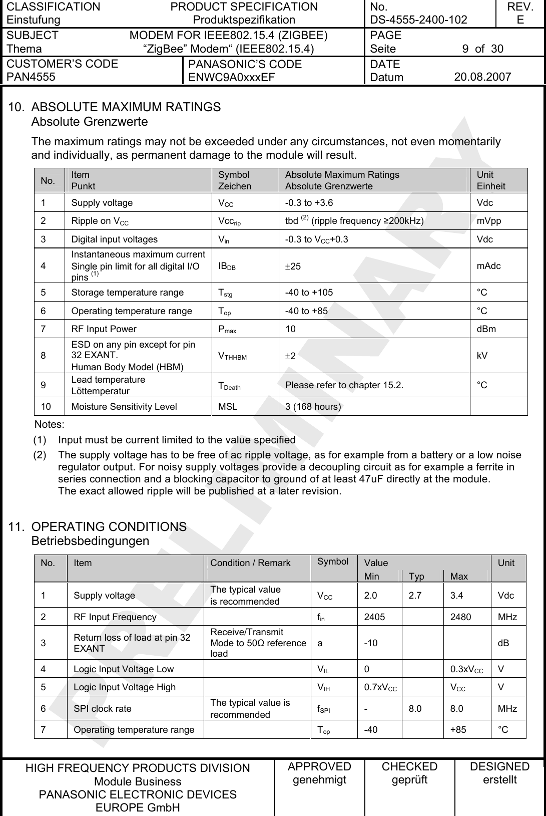
![CLASSIFICATION Einstufung PRODUCT SPECIFICATION Produktspezifikation No. DS-4555-2400-102 REV. E SUBJECT Thema MODEM FOR IEEE802.15.4 (ZIGBEE) “ZigBee” Modem“ (IEEE802.15.4) PAGE Seite 10 of 30 CUSTOMER’S CODE PAN4555 PANASONIC’S CODE ENWC9A0xxxEF DATE Datum 20.08.2007 HIGH FREQUENCY PRODUCTS DIVISION Module Business PANASONIC ELECTRONIC DEVICES EUROPE GmbH APPROVED genehmigt CHECKED geprüft DESIGNED erstellt 12. DC ELECTRICAL CHARACTERISTICS VCC = 2.7V, Tamb = 25°C if nothing else stated No. Item Condition / Remark Symbol Value Unit Min Typ Max 1 Transmit current consumption Transmit Mode (1) ICCT 30 35 mA 2 Receive current consumption Receive Mode ICCR 37 42 mA Off (2) Ileakage 0.2 1.0 µA Hibernate (2) ICCH 1.0 6.0 µA Doze (no CLKO) (2) (3) ICCD 35 102 µA 3 Low power current consumption Idle ICCI 500 800 µA 4 digital I/O pin characteristics Please refer to [2] 6.3.1 MCU DC Characteristics 5 digital I/O pin input capacitance all non-supply pins (4) CIn 7 pF 6 Low voltage warning/detection Power on reset re-arm voltage Please refer to [2] 6.3.1 MCU DC Characteristics Notes: (1) SPI Register 12 is default value of 0x00BC which sets output power to nominal value (2) To attain specified low power current, all GPIO and other digital IO must be handled properly. Detailed description could be found at [2] at section 7.2 Low Power Considerations. (3) CLKO frequency at default value of 32.786 kHz. (4) This parameter is characterized and not tested on each device. 13. A/D CONVERTER CHARACTERISTICS No Item Remark 1 ATD characteristics Please refer to [2] 6.3.3 MCU ATD Characteristics 2 ATD timing/performance characteristics Please refer to [2] 6.3.3 MCU ATD Characteristics The A/D high reference voltage VREFH is connected to pin 6 (VREFH) The A/D low reference voltage VREFL is internally connected to GND.](https://usermanual.wiki/Panasonic-Devices-Europe/PAN4555/User-Guide-837192-Page-10.png)
![CLASSIFICATION Einstufung PRODUCT SPECIFICATION Produktspezifikation No. DS-4555-2400-102 REV. E SUBJECT Thema MODEM FOR IEEE802.15.4 (ZIGBEE) “ZigBee” Modem“ (IEEE802.15.4) PAGE Seite 11 of 30 CUSTOMER’S CODE PAN4555 PANASONIC’S CODE ENWC9A0xxxEF DATE Datum 20.08.2007 HIGH FREQUENCY PRODUCTS DIVISION Module Business PANASONIC ELECTRONIC DEVICES EUROPE GmbH APPROVED genehmigt CHECKED geprüft DESIGNED erstellt 14. AC ELECTRICAL CHARACTERISTICS VCC = 2.7V, Tamb = 25°C, 50Ω load at EXANT, for all channels number 11,12,..., 26 according to [1] No Receiver Limit Unit Nr Empfänger Min Typ Max Einheit 1 Sensitivity for 1% Packet Error Rate (PER), -85dBm required by [1] - -92 -87 dBm 2 Saturation (maximum input level) 0 10 - dBm 3 Adjacent Channel Interference for 1% PER (±5MHz; desired signal -82dBm) 0 29 - dB 4 Alternate Channel Interference for 1% PER (±10MHz; desired signal -82dBm) 0 40 - dB 5 Frequency Error Tolerance - - 200 kHz 6 Symbol Rate Error Tolerance - 80 ppm 7 In-band Spurious Emission - tbd - dBm 8 Spurious Emissions <1GHz - tbd -57 dBm 9 Spurious Emissions >1GHz - tbd -47 dBm No Transmitter Limit Unit Nr Sender Min Typ Max Einheit 1 Maximum Output Power (1) -3.0 0.0 - dBm 2 Nominal Output Power (2) - -4.0 - dBm 3 Minimum Output Power - tbd - dBm 4 Error Vector Magnitude (EVM) - 25 35 % 5 Power Control Range - 30 - dB 6 Over the Air Data Rate - 250 - kbps 7 2nd harmonic @ maximum output power - -50 -30 dBm 8 3rd harmonic @ maximum output power - -60 -30 dBm 9 Spurious Emissions <1GHz - < -40 -36 dBm 10 Spurious Emissions >1GHz - < -40 -30 dBm No Stand By Limit Unit Nr In Bereitschaft Min Typ Max Einheit 1 Spurious Emissions <1GHz - < -60 -57 dBm 2 Spurious Emissions >1GHz - < -50 -47 dBm Notes: (1) SPI Register 12 programmed to 0xFF which sets output power to maximum. Measured at pin EXANT for the SMD pad version. (2) SPI Register 12 programmed to 0xBC which sets output power to nominal. Measured at pin EXANT for the SMD pad version.](https://usermanual.wiki/Panasonic-Devices-Europe/PAN4555/User-Guide-837192-Page-11.png)
![CLASSIFICATION Einstufung PRODUCT SPECIFICATION Produktspezifikation No. DS-4555-2400-102 REV. E SUBJECT Thema MODEM FOR IEEE802.15.4 (ZIGBEE) “ZigBee” Modem“ (IEEE802.15.4) PAGE Seite 12 of 30 CUSTOMER’S CODE PAN4555 PANASONIC’S CODE ENWC9A0xxxEF DATE Datum 20.08.2007 HIGH FREQUENCY PRODUCTS DIVISION Module Business PANASONIC ELECTRONIC DEVICES EUROPE GmbH APPROVED genehmigt CHECKED geprüft DESIGNED erstellt 15. SOLDERING TEMPERATURE-TIME PROFILE (FOR REFLOW SOLDERING) Temperatur-Zeit Profil für die Reflowlötung 15.1. FOR LEAD SOLDER Recommended temp. profile for reflow soldering Temp.[°C] Time [s] 235°C max. 220 ±5°C 200°C150 ±10°C 90 ±30s 10 ±1s 30 +20/-10s 15.2. FOR LEADFREE SOLDER Our used temp. profile for reflow soldering Temp.[°C] Time [s] 230°C -250°C max. 220°C150°C – 190°C 90 ±30s 30 +20/-10s Reflow permissible cycle: 2 Opposite side reflow is prohibited due to module weight.](https://usermanual.wiki/Panasonic-Devices-Europe/PAN4555/User-Guide-837192-Page-12.png)
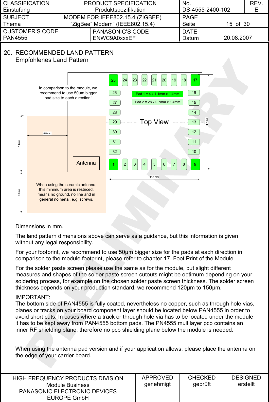
![CLASSIFICATION Einstufung PRODUCT SPECIFICATION Produktspezifikation No. DS-4555-2400-102 REV. E SUBJECT Thema MODEM FOR IEEE802.15.4 (ZIGBEE) “ZigBee” Modem“ (IEEE802.15.4) PAGE Seite 14 of 30 CUSTOMER’S CODE PAN4555 PANASONIC’S CODE ENWC9A0xxxEF DATE Datum 20.08.2007 HIGH FREQUENCY PRODUCTS DIVISION Module Business PANASONIC ELECTRONIC DEVICES EUROPE GmbH APPROVED genehmigt CHECKED geprüft DESIGNED erstellt 18. LABELING DRAWING Kennzeichnung des Moduls durch Label This label is suitable for reflow soldering and designed for the engineering sample status. Information in the 2D-Barcode are the date cin the format Year-Month-Day [6 signs], serial number [6 signs], ordering number [8 signs; without ENW and F], the identifier for the hardware release [2 signs, now 01] and the ES, separated by a semicolon. ode ES stands for Engineering Samples, please refer to chapter General Information. In mass production status, the ES will be eliminated and replaced by a software identifier. And will be also implemented at the last information in the 2D-Barcode. The point on the label is the identifier for pin 1 of the module. 01 is the hardware revision. 7.5 mm12.2 mm19. MECHANICAL REQUIREMENTS Mechanische Anforderungen No. Item Punkt Limit Grenzwerte Condition Bedingung 1 Solderability Lötfähigkeit More than 75% of the soldering area shall be coated by solder Mehr als 75% der Lötfläche soll mit Lötpaste bedeckt sein. Reflow soldering with recommendable temperature profile 2 Resistance to soldering heat It shall be satisfied electrical requirements and not be mechanical damage Please refer to chapter 15.2.](https://usermanual.wiki/Panasonic-Devices-Europe/PAN4555/User-Guide-837192-Page-14.png)
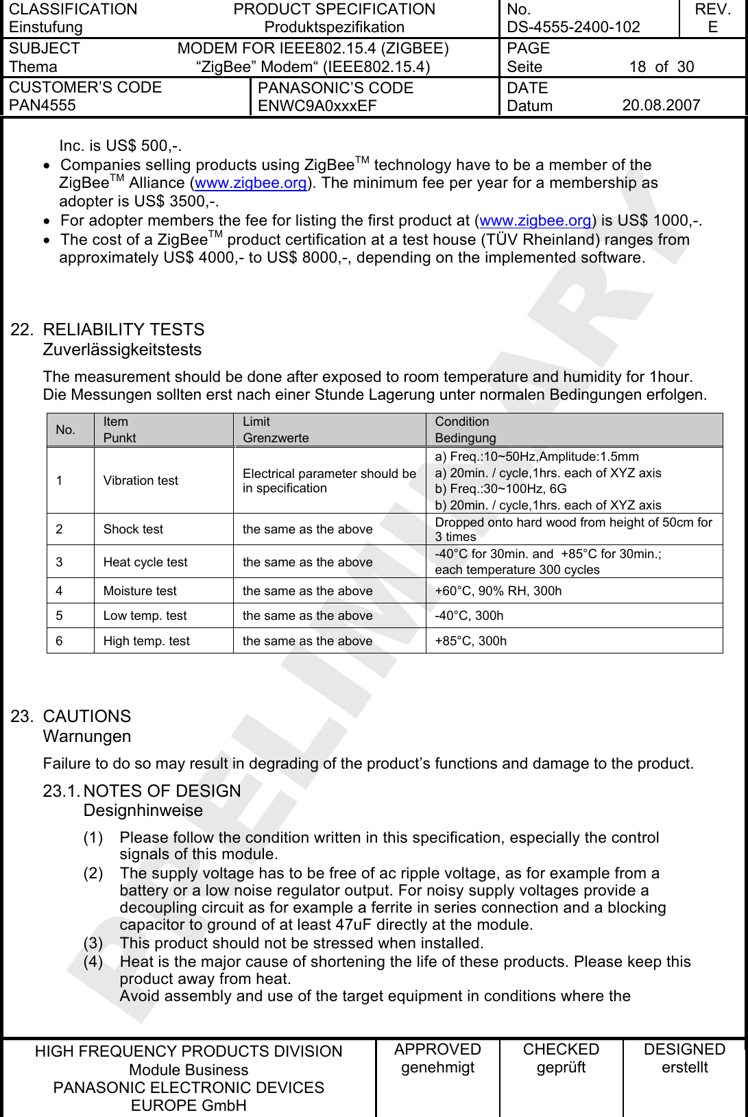
![CLASSIFICATION Einstufung PRODUCT SPECIFICATION Produktspezifikation No. DS-4555-2400-102 REV. E SUBJECT Thema MODEM FOR IEEE802.15.4 (ZIGBEE) “ZigBee” Modem“ (IEEE802.15.4) PAGE Seite 17 of 30 CUSTOMER’S CODE PAN4555 PANASONIC’S CODE ENWC9A0xxxEF DATE Datum 20.08.2007 HIGH FREQUENCY PRODUCTS DIVISION Module Business PANASONIC ELECTRONIC DEVICES EUROPE GmbH APPROVED genehmigt CHECKED geprüft DESIGNED erstellt 21. DEVELOPMENT OF APPLICATIONS WITH FREESCALE BEESTACKTM Entwiclung von Applikationen mit Hilfe des BeeStacks von freescale This chapter are copied from [8], please refer to this document to get more information. PAN4555 is built around the MC13213 single package from Freescale Inc. which includes the freescale ZigBee codebase BeeStackTM (downscaled versions of PAN4555 with MC1321x suited for IEEE802.15.4 or SMAC only are available on demand as well). The access to BeeStackPTMP is provided after registration and login at http://www.freescale.com/zigbee . After login the BEEKITDOWNLOADPACKAGE.zip can be downloaded. This package contains BeeStackPTMP , IEEE802.15.4 MAC and SMAC codebases. For PAN4555 PHY testing using TestToolPTM P the download of the latest 1321xEVK package is recommended. After successful installation of Beekit on a PC open BeeKit. A ZigBee sample solution *.bksln can be created in a few steps. Important: Before a solution may be exported for PAN4555 the MC1321x target settings have to be changed via the “User defined target editor”. The required changes are: • Uncheck the “Use external Antenna Switch” • Adjust the port settings depending on your application, the PAN4555 datasheet and for use of the PAN4555 carrier board the pin list in chapter PAN4555 PINLIST at [8]. For importing, compiling and debugging of the BeeKitTM solution the Integrated Development Environment (IDE) MetrowerksPTM PCodeWarrior from www.metrowerks.com is required. As device flash programmer the USB HCS08/HCS12 Multilink from www.pemicro.com is recommended. Important: PAN4555 is a single RF port design with MC13213, refer also to AN3248. The Freescale reference boards 13213-NCB and 13213-SRB are dual port designs, software for these boards will not run. The shipping of products which use ZigBeeTM technology requires a membership of the ZigBeeTM Alliance (www.zigbee.org), at least as an adopter member, and is mandatory for the ZigBeeTM product certification procedure and use of the ZigBeeTM Logo. The prices and fees as known from today are as follows: • IDE CodeWarrior order number CWS-H08-C64K-CX from www.metrowerks.com : US$ 995,-. • USB HCS08/HCS12 Multilink (www.pemicro.com), orderable at www.freescale.com/zigbee with the ID USBMULTILINKBDM: US$ 99,- • BeeStackTM: The support fee after a 30 days period free of charge required by Freescale](https://usermanual.wiki/Panasonic-Devices-Europe/PAN4555/User-Guide-837192-Page-17.png)
![CLASSIFICATION Einstufung PRODUCT SPECIFICATION Produktspezifikation No. DS-4555-2400-102 REV. E SUBJECT Thema MODEM FOR IEEE802.15.4 (ZIGBEE) “ZigBee” Modem“ (IEEE802.15.4) PAGE Seite 24 of 30 CUSTOMER’S CODE PAN4555 PANASONIC’S CODE ENWC9A0xxxEF DATE Datum 20.08.2007 HIGH FREQUENCY PRODUCTS DIVISION Module Business PANASONIC ELECTRONIC DEVICES EUROPE GmbH APPROVED genehmigt CHECKED geprüft DESIGNED erstellt 24.5. LABEL FOR PACKAGE The label must be stick 3 times, reel, barrier bag and inner carton box. 70,00mm(P)P/NPAN4555(1P)PO No.ENWC9A08A3EFDescr iptionES SampleES Status(Q)QTY500MSL tbdTmax tbd(D)DATE CODE7419[[G]]MADE INGERMANY24.6. TOTAL PACKING HANDLING](https://usermanual.wiki/Panasonic-Devices-Europe/PAN4555/User-Guide-837192-Page-24.png)
![CLASSIFICATION Einstufung PRODUCT SPECIFICATION Produktspezifikation No. DS-4555-2400-102 REV. E SUBJECT Thema MODEM FOR IEEE802.15.4 (ZIGBEE) “ZigBee” Modem“ (IEEE802.15.4) PAGE Seite 29 of 30 CUSTOMER’S CODE PAN4555 PANASONIC’S CODE ENWC9A0xxxEF DATE Datum 20.08.2007 HIGH FREQUENCY PRODUCTS DIVISION Module Business PANASONIC ELECTRONIC DEVICES EUROPE GmbH APPROVED genehmigt CHECKED geprüft DESIGNED erstellt 29. RELATED DOCUMENTS Mitgeltende Dokumente For an update, please search in the suitable homepage. [1] IEEE Standard 802.15.4 –2003 Wireless Medium Access Control (MAC) and Physical Layer (PHY) Specifications for Low-Rate Wireless Personal Area Networks (LR-WPANs) [2] Technical Data MC1321x Document Number: MC1321x Rev. 1.1, 03/2007 Freescale Semiconductor [3] MC1321x Reference Manual Document Number: MC1321xRM Rev. 1.1, 10/2006 Freescale Semiconductor [4] Handling MAC Address erasure, AN2825, Rev. 0.0 10/2004, Freescale Semiconductor [5] 802154MPSUG 802.15.4 MAC/PHY Software User´s Guide, Rev 1.1, Freescale Semiconductor [6] 802154EBRM.pdf 802.15.4 / ZigBee Embedded Bootloader Reference Manual Rev. 0.0 09/2004 [7] AN2771 ZigBee/802.15.4 PHY Protocol Test Client (PTC) Rev. 0.0 Freescale Semiconductor [8] Manual to the Evaluation Kit from Panasonic Downloadable under: www.pedeu.panasonic.de.](https://usermanual.wiki/Panasonic-Devices-Europe/PAN4555/User-Guide-837192-Page-29.png)