Panasonic Devices Europe PAN4555 ZigBeeTM-Module PAN4555 User Manual 1
Panasonic Industrial Devices Europe GmbH ZigBeeTM-Module PAN4555 1
Manual

CLASSIFICATION
Einstufung
PRODUCT SPECIFICATION
Produktspezifikation
No.
DS-4555-2400-102
REV.
E
SUBJECT
Thema
MODEM FOR IEEE802.15.4 (ZIGBEE)
“ZigBee” Modem“ (IEEE802.15.4)
PAGE
Seite
1 of 30
CUSTOMER’S CODE
PAN4555
PANASONIC’S CODE
ENWC9A0xxxEF
DATE
Datum
20.08.2007
HIGH FREQUENCY PRODUCTS DIVISION
Module Business
PANASONIC ELECTRONIC DEVICES
EUROPE GmbH
APPROVED
genehmigt
CHECKED
geprüft
DESIGNED
erstellt
Specification for Production
Panasonic Electronic Devices Europe GmbH
Zeppelinstrasse 19
21337 Lüneburg
Applicant / Manufacturer
Hardware
Germany
Freescale Semiconductor Inc.
Applicant / Manufacturer
Software
Contents Approval for Mass Production
Customer
By signing this document, Customer accepts the validity of the below-mentioned
contents and declares his full notice to it. Some passages may be changed if required;
the validity shall not be affected thereby.
CHECKED / APPROVED:
DATE: NAME: SIGNATURE:
NOTE:
AT LEAST ONE SET OF APPROVED SPECIFICATIONS SHOULD BE RETURNED TO
THE ADDRESS OF THE ISSUING PARTY.

CLASSIFICATION
Einstufung
PRODUCT SPECIFICATION
Produktspezifikation
No.
DS-4555-2400-102
REV.
E
SUBJECT
Thema
MODEM FOR IEEE802.15.4 (ZIGBEE)
“ZigBee” Modem“ (IEEE802.15.4)
PAGE
Seite
2 of 30
CUSTOMER’S CODE
PAN4555
PANASONIC’S CODE
ENWC9A0xxxEF
DATE
Datum
20.08.2007
HIGH FREQUENCY PRODUCTS DIVISION
Module Business
PANASONIC ELECTRONIC DEVICES
EUROPE GmbH
APPROVED
genehmigt
CHECKED
geprüft
DESIGNED
erstellt
TABLE OF CONTENTS
1. Key Features...................................................................................................................4
2. Applications for the Module.............................................................................................4
3. Description of the Module................................................................................................5
4. Scope of this Document ..................................................................................................5
5. History for this Document................................................................................................5
6. Terminal Layout...............................................................................................................6
7. Block Diagram.................................................................................................................8
8. Key Parts List ..................................................................................................................8
9. Test Conditions ...............................................................................................................8
10. Absolute Maximum Ratings.............................................................................................9
11. Operating Conditions.......................................................................................................9
12. DC Electrical Characteristics.........................................................................................10
13. A/D converter Characteristics........................................................................................10
14. AC Electrical Characteristics.........................................................................................11
15. Soldering Temperature-Time Profile (for reflow soldering) ...........................................12
15.1. For lead solder .....................................................................................................12
15.2. For leadfree solder...............................................................................................12
16. Module Dimension.........................................................................................................13
17. Foot Print of the Module................................................................................................13
18. Labeling Drawing...........................................................................................................14
19. Mechanical Requirements.............................................................................................14
20. Recommended Land Pattern ........................................................................................15
21. Development of Applications with freescale BeeStackTM ..............................................17
22. Reliability Tests .............................................................................................................18
23. Cautions ........................................................................................................................18
23.1. Notes of design ....................................................................................................18
23.2. Notes of installation..............................................................................................19
23.3. Notes of usage conditions....................................................................................19
23.4. Notes of storage...................................................................................................20
23.5. Cautions for safety ...............................................................................................20
23.6. Other cautions......................................................................................................20
24. Packaging......................................................................................................................22
24.1. Tape Dimension...................................................................................................22
24.2. Packing in Tape ...................................................................................................22
24.3. Component direction............................................................................................23
24.4. Reel Dimension....................................................................................................23
24.5. Label for Package ................................................................................................24
24.6. Total Packing Handling ........................................................................................24

CLASSIFICATION
Einstufung
PRODUCT SPECIFICATION
Produktspezifikation
No.
DS-4555-2400-102
REV.
E
SUBJECT
Thema
MODEM FOR IEEE802.15.4 (ZIGBEE)
“ZigBee” Modem“ (IEEE802.15.4)
PAGE
Seite
3 of 30
CUSTOMER’S CODE
PAN4555
PANASONIC’S CODE
ENWC9A0xxxEF
DATE
Datum
20.08.2007
HIGH FREQUENCY PRODUCTS DIVISION
Module Business
PANASONIC ELECTRONIC DEVICES
EUROPE GmbH
APPROVED
genehmigt
CHECKED
geprüft
DESIGNED
erstellt
24.7. Cover tape reel strength ......................................................................................25
25. Ordering Information .....................................................................................................25
26. RoHS Declaration..........................................................................................................26
27. Data Sheet Status .........................................................................................................26
28. Regulatory Information..................................................................................................26
28.1. FCC Notice ..........................................................................................................26
28.2. Caution.................................................................................................................27
28.3. Labeling Requirements ........................................................................................27
28.4. Antenna Warning .................................................................................................27
28.5. Approved Antenna List.........................................................................................28
28.6. RF Exposure PAN4555........................................................................................28
29. Related Documents.......................................................................................................29
30. General Information.......................................................................................................30
31. Life Support Policy ........................................................................................................30

CLASSIFICATION
Einstufung
PRODUCT SPECIFICATION
Produktspezifikation
No.
DS-4555-2400-102
REV.
E
SUBJECT
Thema
MODEM FOR IEEE802.15.4 (ZIGBEE)
“ZigBee” Modem“ (IEEE802.15.4)
PAGE
Seite
4 of 30
CUSTOMER’S CODE
PAN4555
PANASONIC’S CODE
ENWC9A0xxxEF
DATE
Datum
20.08.2007
HIGH FREQUENCY PRODUCTS DIVISION
Module Business
PANASONIC ELECTRONIC DEVICES
EUROPE GmbH
APPROVED
genehmigt
CHECKED
geprüft
DESIGNED
erstellt
1. KEY FEATURES
Schlüsseleigenschaften
• Short range 2,4GHz ISM band transceiver with microcontroller and reference oscillator
• Provides complete hardware for a wireless node using IEEE802.15.4 packet structure
• Very small size (12.2mm x 16.4mm x 2.2mm)
• 2 antenna options: Single port 50 or ceramic antenna
• 16 selectable Channels with 250 kbps in the 2.4 GHz band
• Low power modes for increased battery life
• High sensitivity of -92 dBm typ. at 1% Packet Error Rate
• 0 dBm typ. output power programmable over a 30 dB range
• Low supply voltage (2.0 V to 3.4 V, 2.7 V typ.)
• Operating temperature range -40°C to +85°C
• Link Quality and Clear Channel Assessment capability
• 60k Flash and 4k RAM memory
• 4 channel A/D converter with 10 Bit for fast and easy conversion from analog inputs -such
as temperature, pressure and fluid levels- to digital values.
• 3 channel 16 Bit timer/pulse width modulation (TPM) outputs
• BDM port for direct download programming
• In total 20 digital I/O lines with programmable pull-ups and few with high-current driver.
• Low power modes for increased battery life
• Low battery warning
• Low voltage detect/reset
• Complies with ETSI EN300328 and FCC Part 15C
2. APPLICATIONS FOR THE MODULE
Anwendungen für das Modul
• ZigBeeTM FFD (full functional) and RFD (reduced functional)
devices working in star and mesh networks
• Wireless sensor and actuator networks
• Remote control and wire replacement in industrial systems
• Factory and home automation and control
• Inventory and logistics management
• HID (Human Interface Devices)
• Toys
• Home gateways
• proprietary networking solutions using IEEE802.15.4
CLASSIFICATION
Einstufung
PRODUCT SPECIFICATION
Produktspezifikation
No.
DS-4555-2400-102
REV.
E
SUBJECT
Thema
MODEM FOR IEEE802.15.4 (ZIGBEE)
“ZigBee” Modem“ (IEEE802.15.4)
PAGE
Seite
5 of 30
CUSTOMER’S CODE
PAN4555
PANASONIC’S CODE
ENWC9A0xxxEF
DATE
Datum
20.08.2007
HIGH FREQUENCY PRODUCTS DIVISION
Module Business
PANASONIC ELECTRONIC DEVICES
EUROPE GmbH
APPROVED
genehmigt
CHECKED
geprüft
DESIGNED
erstellt
3. DESCRIPTION OF THE MODULE
Beschreibung des Moduls
The PAN4555 module is a short range, low power, 2.4 GHz ISM band transceiver which
includes a complete 802.15.4 physical layer (PHY) modem, designed for the IEEE 802.15.4
wireless standard and a appropriate microcontroller (MCU) with reference oscillator which
provides a cost effective solution for short-range data links and networks.
The main purpose of PAN4555 are ZigBeeTM (www.zigbee.org) applications based on
“BeeStack” of Freescale Inc.. For details on ZigBee application software see chapter 21.
TM
Proprietary networking solutions on top of the IEEE802.15.4 MAC/PHY software package
(available at www.freescale.com/zigbee) could be implemented instead of ZigBee as well.
TM
As Integrated Development Environment (IDE) the MetrowerksTM CodeWarrior IDE from
www.metrowerks.com is required. For device flash programming via the BDM port of PAN4555
the USB HCS08/HCS12 Multilink from www.pemicro.com is recommended.
4. SCOPE OF THIS DOCUMENT
Umfang dieses Dokumentes
This product specification applies to the ZigBee ready modem ENWC9A0xxxE.
The xxx is the indicator for different versions (refer to chapter 25 Ordering Information).
The used ZigBee chip is the MC13213 from the US company freescale
www.freescale.com/zigbee.
Diese Produktionsunterlagen beziehen sich auf das ZigBee ready Modem ENWC9A0xxxE
Die Zeichen xxx bezeichnen verschiedene Versionen (Erklärung im Kapitel 25 Ordering
Information).
Der verwendete ZigBee Chip ist der MC13213 der US Firma Freescale.
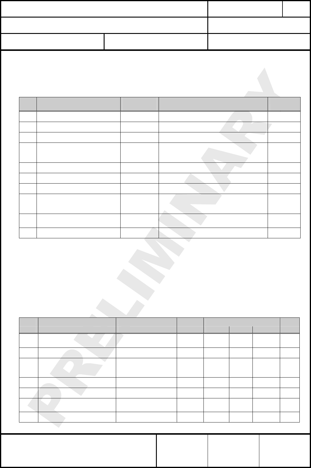
5. HISTORY FOR THIS DOCUMENT
Versionsverwaltung dieses Dokumentes
Revision
Version
Date
Datum
Modification / Remarks
Änderungen / Bemerkungen
A 26.04.2007 Initial draft version
B 08.06.2007 Corrected pin14 in chapter Terminal Layout and revised chapter Block Diagram.
C 28.06.2007 Change IC name from MC13214 to MC13213 in chapter 21.
D 11.07.2007
Support fee reduced to $500 in chapter 21. Change MOQ from 1500pcs to
500pcs. Add special note (2) for the ripple on supply voltage.
E 20.08.2007 Add chapter Regulatory Information.
CLASSIFICATION
Einstufung
PRODUCT SPECIFICATION
Produktspezifikation
No.
DS-4555-2400-102
REV.
E
SUBJECT
Thema
MODEM FOR IEEE802.15.4 (ZIGBEE)
“ZigBee” Modem“ (IEEE802.15.4)
PAGE
Seite
6 of 30
CUSTOMER’S CODE
PAN4555
PANASONIC’S CODE
ENWC9A0xxxEF
DATE
Datum
20.08.2007
HIGH FREQUENCY PRODUCTS DIVISION
Module Business
PANASONIC ELECTRONIC DEVICES
EUROPE GmbH
APPROVED
genehmigt
CHECKED
geprüft
DESIGNED
erstellt
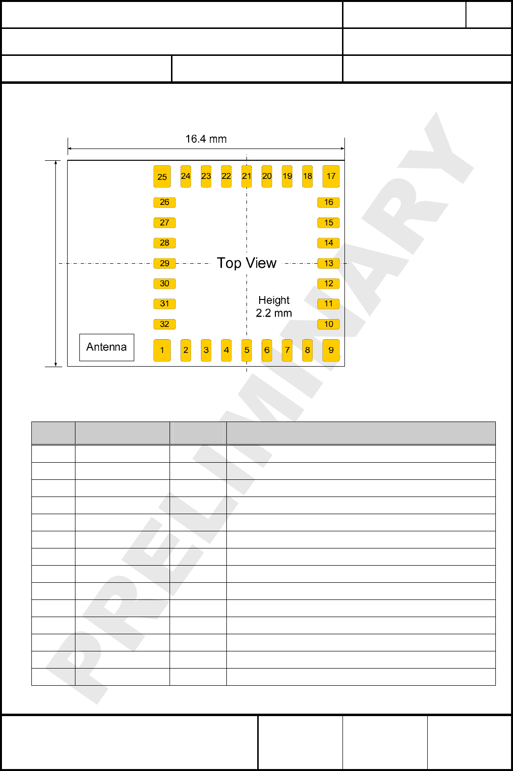
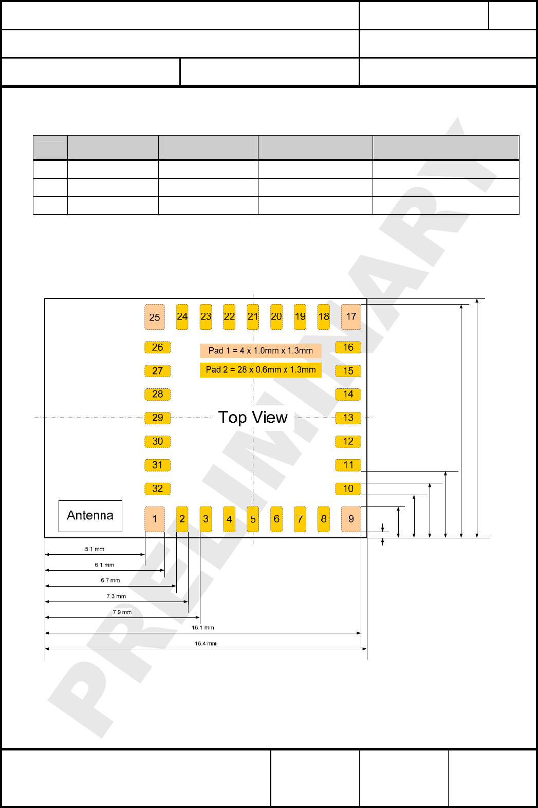
6. TERMINAL LAYOUT
Anschlußbelegung
Please refer also to the MC1321x technical data sheet and reference manual, which is given in
[2] and [3] in chapter Related Documents.
12.2 mm
Pin
No.
Pin
Name
Pin
Type Description
1 GND I/O Ground
2 PTB0 / AD1P0 I/O MCU Port B Bit 0 / ATD analog Channel 0
3 PTB1 / AD1P1 I/O MCU Port B Bit 1 / ATD analog Channel 1
4 PTB2 / AD1P2 I/O MCU Port B Bit 2 / ATD analog Channel 2
5 PTB7/AD1P7 I/O MCU Port B Bit 7 / ATD analog Channel 7
6 VREFH I MCU high reference voltage for ATD
7 PTA7 / KBI1P7 Dig. I/O MCU Port A Bit 7 / Keyboard Input Bit 7
8 PTA5 / KBI1P5 Dig. I/O MCU Port A Bit 5 / Keyboard Input Bit 5
9 GND I/O Ground
10 PTA6 / KBI1P6 Dig. I/O MCU Port A Bit 6 / Keyboard Input Bit 6
11 PTG0 / BKGND / MS Dig. I/O MCU Port G Bit 0 / Background / Mode Select (1)
12 PTG1 / XTAL Dig. I/O / O MCU Port G Bit 1 / Crystal oscillator output (2)
13 PTG2 / EXTAL Dig. I/O / I MCU Port G Bit 2 / Crystal oscillator input (2) (3)
14 CLKO O Programmable Clock Output (default: 32,768 kHz) (3)
CLASSIFICATION
Einstufung
PRODUCT SPECIFICATION
Produktspezifikation
No.
DS-4555-2400-102
REV.
E
SUBJECT
Thema
MODEM FOR IEEE802.15.4 (ZIGBEE)
“ZigBee” Modem“ (IEEE802.15.4)
PAGE
Seite
7 of 30
CUSTOMER’S CODE
PAN4555
PANASONIC’S CODE
ENWC9A0xxxEF
DATE
Datum
20.08.2007
HIGH FREQUENCY PRODUCTS DIVISION
Module Business
PANASONIC ELECTRONIC DEVICES
EUROPE GmbH
APPROVED
genehmigt
CHECKED
geprüft
DESIGNED
erstellt
Pin
No.
Pin
Name
Pin
Type Description
15 PTC0 / TXD2 Dig. I/O MCU Port C Bit 0 / SCI2 TX data out
16 PTC1 / RXD2 Dig. I/O MCU Port C Bit 1/ SCI2 RX data in
17 GND I/O Ground
18 PTC5 Dig. I/O MCU Port C Bit 5
19 PTC3 / SCL1 Dig. I/O MCU Port C Bit 1/ IIC bus clock
20 PTC2 / SDA1 Dig. I/O MCU Port C Bit 1/ IIC bus clock
21 PTE0 / TXD1 Dig. I/O MCU Port E Bit 0 / SCI1 TX data out
22 PTE1 / RXD1 Dig. I/O MCU Port E Bit 1/ SCI1 RX data in
23 VDDA Power O Modem analog regulated supply output
24 Vcc Power I Modem voltage regulators’ input
25 GND I/O Ground
26 Vcc Power I Modem voltage regulators’ input
27 RESET Dig. I/O MCU reset. Active low
28 PTD6 / TPM2CH3 Dig. I/O MCU Port D Bit 6 / TPM2 Channel 3
29 PTD4 / TPM2CH1 Dig. I/O MCU Port D Bit 4 / TPM2 Channel 1
30 PTD2 / TPM1CH2 Dig. I/O MCU Port D Bit 2 / TPM1 Channel 2
31 GND I/O Ground
32 EXANT I/O Pin for external antenna (50 Ω)
Note:
(1) PTG0 is output only. Pin is I/O when used as BDM function.
(2) Full I/O when not used as clock source. Please refer also to [2].
(3) CLKO (Pin 14) and PTG2/EXTAL (Pin 13) must be connected externally if the microcontroller should
use the programmable clock derived from the internal 16 MHz crystal.
CLASSIFICATION
Einstufung
PRODUCT SPECIFICATION
Produktspezifikation
No.
DS-4555-2400-102
REV.
E
SUBJECT
Thema
MODEM FOR IEEE802.15.4 (ZIGBEE)
“ZigBee” Modem“ (IEEE802.15.4)
PAGE
Seite
8 of 30
CUSTOMER’S CODE
PAN4555
PANASONIC’S CODE
ENWC9A0xxxEF
DATE
Datum
20.08.2007
HIGH FREQUENCY PRODUCTS DIVISION
Module Business
PANASONIC ELECTRONIC DEVICES
EUROPE GmbH
APPROVED
genehmigt
CHECKED
geprüft
DESIGNED
erstellt
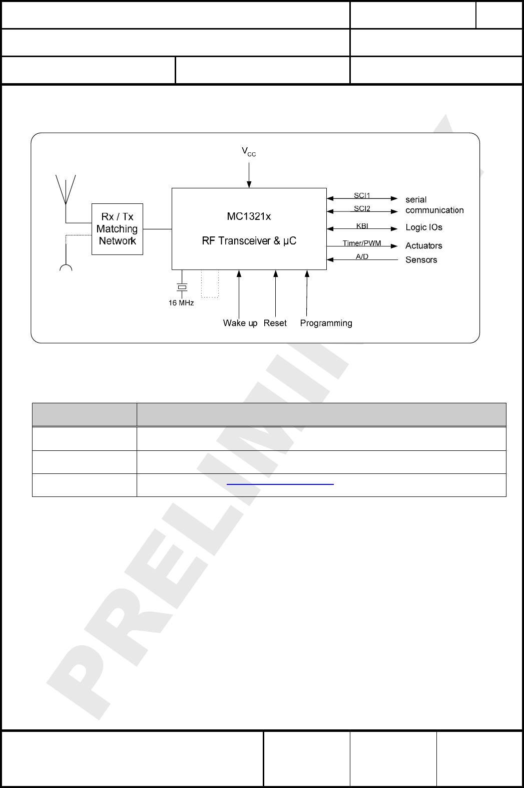
7. BLOCK DIAGRAM
Blockdiagramm
BKGD
CLKO
EXTAL
8. KEY PARTS LIST
Liste der Schlüsselkomponenten
Part Name
Teilenummer
Material
Material
P.W.Board
Leiterplatte
Glass cloth epoxide resin with gold plating
FR4 mit Goldauflage
Casing
Deckel
Material: BZn15-20, thickness 0.15mm
Material: Weißblech 0,15mm Dicke
IC part name
IC Name
MC13213 (freescale www.freescale.com/zigbee)
All information are based on [2] chapter 28
9. TEST CONDITIONS
Meßbedingungen
Measurements shall be made under room temperature and humidity unless otherwise specified.
Messungen unter normalen Bedingungen, Abweichungen sind gesondert notiert.
Temperature 25 ± 10°C Humidity 40 to 85%RH
Temperatur 25 ± 10°C Luftfeuchtigkeit 40 to 85%RH
CLASSIFICATION
Einstufung
PRODUCT SPECIFICATION
Produktspezifikation
No.
DS-4555-2400-102
REV.
E
SUBJECT
Thema
MODEM FOR IEEE802.15.4 (ZIGBEE)
“ZigBee” Modem“ (IEEE802.15.4)
PAGE
Seite
9 of 30
CUSTOMER’S CODE
PAN4555
PANASONIC’S CODE
ENWC9A0xxxEF
DATE
Datum
20.08.2007
HIGH FREQUENCY PRODUCTS DIVISION
Module Business
PANASONIC ELECTRONIC DEVICES
EUROPE GmbH
APPROVED
genehmigt
CHECKED
geprüft
DESIGNED
erstellt
10. ABSOLUTE MAXIMUM RATINGS
Absolute Grenzwerte
The maximum ratings may not be exceeded under any circumstances, not even momentarily
and individually, as permanent damage to the module will result.
No. Item
Punkt
Symbol
Zeichen
Absolute Maximum Ratings
Absolute Grenzwerte
Unit
Einheit
1 Supply voltage VCC -0.3 to +3.6 Vdc
2 Ripple on VCC Vccrip tbd (2) (ripple frequency 200kHz) mVpp
3 Digital input voltages Vin -0.3 to VCC+0.3 Vdc
4
Instantaneous maximum current
Single pin limit for all digital I/O
pins (1)
IBDB ±25 mAdc
5 Storage temperature range Tstg -40 to +105 °C
6 Operating temperature range Top -40 to +85 °C
7 RF Input Power Pmax 10 dBm
8
ESD on any pin except for pin
32 EXANT.
Human Body Model (HBM)
VTHHBM ±2 kV
9 Lead temperature
Löttemperatur TDeath Please refer to chapter 15.2. °C
10 Moisture Sensitivity Level MSL 3 (168 hours)
Notes:
(1) Input must be current limited to the value specified
(2) The supply voltage has to be free of ac ripple voltage, as for example from a battery or a low noise
regulator output. For noisy supply voltages provide a decoupling circuit as for example a ferrite in
series connection and a blocking capacitor to ground of at least 47uF directly at the module.
The exact allowed ripple will be published at a later revision.
11. OPERATING CONDITIONS
Betriebsbedingungen
No. Item Condition / Remark Symbol Value Unit
Min Typ Max
1 Supply voltage The typical value
is recommended VCC 2.0 2.7 3.4 Vdc
2 RF Input Frequency fin 2405 2480 MHz
3 Return loss of load at pin 32
EXANT
Receive/Transmit
Mode to 50 reference
load
a -10 dB
4 Logic Input Voltage Low VIL 0 0.3xVCC V
5 Logic Input Voltage High VIH 0.7xVCC V
CC V
6 SPI clock rate The typical value is
recommended fSPI - 8.0 8.0 MHz
7 Operating temperature range Top -40 +85 °C
CLASSIFICATION
Einstufung
PRODUCT SPECIFICATION
Produktspezifikation
No.
DS-4555-2400-102
REV.
E
SUBJECT
Thema
MODEM FOR IEEE802.15.4 (ZIGBEE)
“ZigBee” Modem“ (IEEE802.15.4)
PAGE
Seite
10 of 30
CUSTOMER’S CODE
PAN4555
PANASONIC’S CODE
ENWC9A0xxxEF
DATE
Datum
20.08.2007
HIGH FREQUENCY PRODUCTS DIVISION
Module Business
PANASONIC ELECTRONIC DEVICES
EUROPE GmbH
APPROVED
genehmigt
CHECKED
geprüft
DESIGNED
erstellt
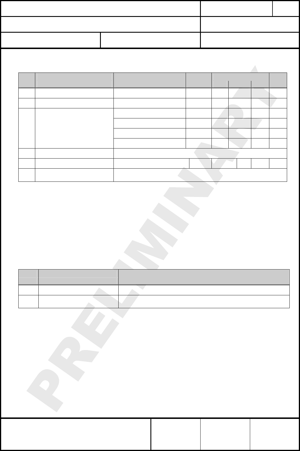
12. DC ELECTRICAL CHARACTERISTICS
VCC = 2.7V, Tamb = 25°C if nothing else stated
No. Item Condition / Remark Symbol Value Unit
Min Typ Max
1 Transmit current consumption Transmit Mode (1) I
CCT 30 35 mA
2 Receive current consumption Receive Mode ICCR 37 42 mA
Off (2) I
leakage 0.2 1.0 µA
Hibernate (2) I
CCH 1.0 6.0 µA
Doze (no CLKO) (2) (3) ICCD 35 102 µA
3 Low power current
consumption
Idle ICCI 500 800 µA
4 digital I/O pin characteristics Please refer to [2] 6.3.1 MCU DC Characteristics
5 digital I/O pin input capacitance all non-supply pins
(4) C
In 7 pF
6 Low voltage warning/detection
Power on reset re-arm voltage Please refer to [2] 6.3.1 MCU DC Characteristics
Notes:
(1) SPI Register 12 is default value of 0x00BC which sets output power to nominal value
(2) To attain specified low power current, all GPIO and other digital IO must be handled properly.
Detailed description could be found at [2] at section 7.2 Low Power Considerations.
(3) CLKO frequency at default value of 32.786 kHz.
(4) This parameter is characterized and not tested on each device.
13. A/D CONVERTER CHARACTERISTICS
No Item
Remark
1 ATD characteristics Please refer to [2] 6.3.3 MCU ATD Characteristics
2 ATD timing/performance
characteristics Please refer to [2] 6.3.3 MCU ATD Characteristics
The A/D high reference voltage VREFH is connected to pin 6 (VREFH)
The A/D low reference voltage VREFL is internally connected to GND.
CLASSIFICATION
Einstufung
PRODUCT SPECIFICATION
Produktspezifikation
No.
DS-4555-2400-102
REV.
E
SUBJECT
Thema
MODEM FOR IEEE802.15.4 (ZIGBEE)
“ZigBee” Modem“ (IEEE802.15.4)
PAGE
Seite
11 of 30
CUSTOMER’S CODE
PAN4555
PANASONIC’S CODE
ENWC9A0xxxEF
DATE
Datum
20.08.2007
HIGH FREQUENCY PRODUCTS DIVISION
Module Business
PANASONIC ELECTRONIC DEVICES
EUROPE GmbH
APPROVED
genehmigt
CHECKED
geprüft
DESIGNED
erstellt
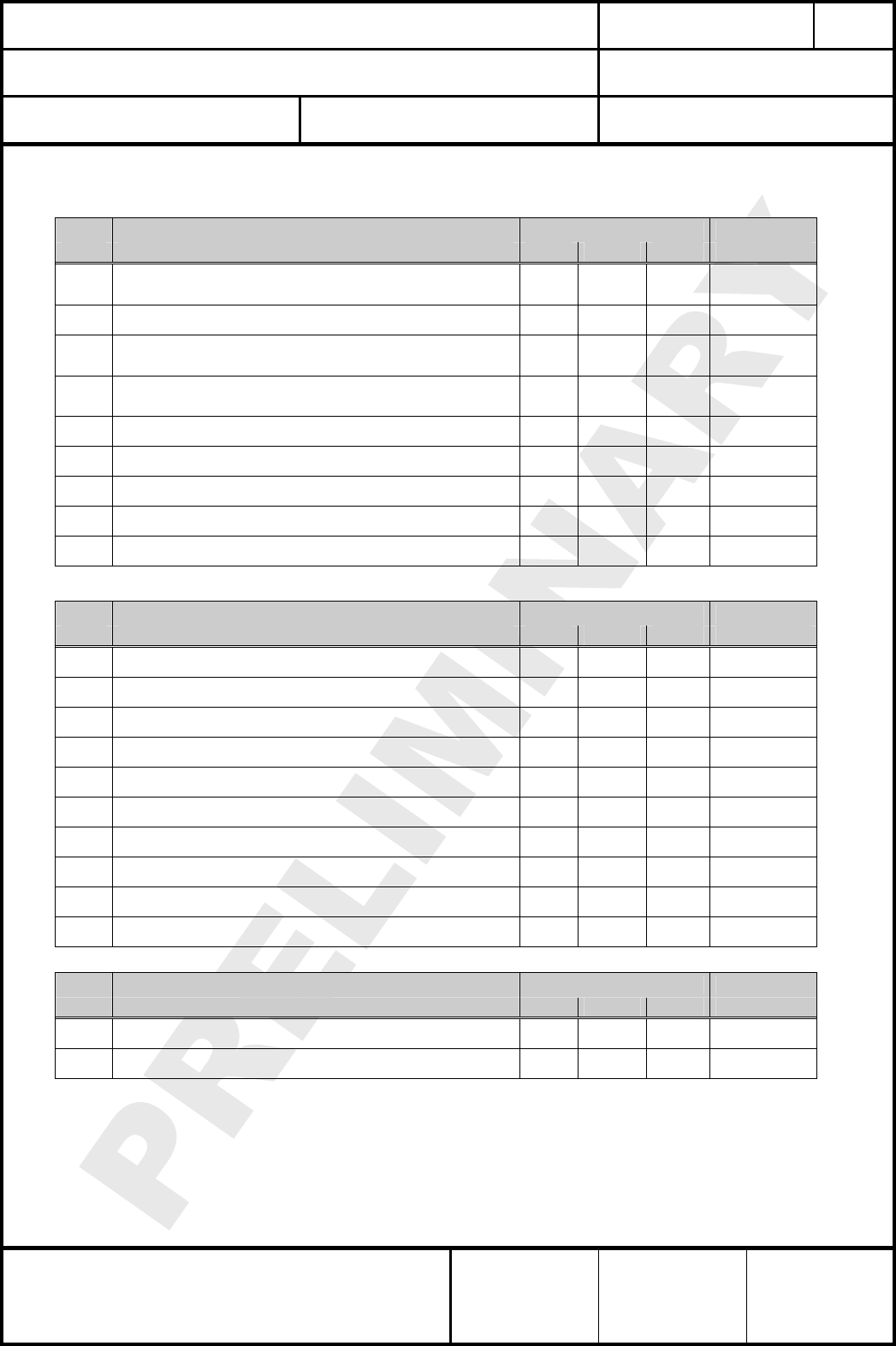
14. AC ELECTRICAL CHARACTERISTICS
VCC = 2.7V, Tamb = 25°C, 50Ω load at EXANT, for all channels number 11,12,..., 26 according to [1]
No Receiver Limit Unit
Nr Empfänger Min Typ Max Einheit
1 Sensitivity for 1% Packet Error Rate (PER),
-85dBm required by [1] - -92 -87 dBm
2 Saturation (maximum input level) 0 10 - dBm
3 Adjacent Channel Interference for 1% PER
(±5MHz; desired signal -82dBm) 0 29 - dB
4 Alternate Channel Interference for 1% PER
(±10MHz; desired signal -82dBm) 0 40 - dB
5 Frequency Error Tolerance - - 200 kHz
6 Symbol Rate Error Tolerance - 80 ppm
7 In-band Spurious Emission - tbd - dBm
8 Spurious Emissions <1GHz - tbd -57 dBm
9 Spurious Emissions >1GHz - tbd -47 dBm
No Transmitter Limit Unit
Nr Sender Min Typ Max Einheit
1 Maximum Output Power (1) -3.0 0.0 - dBm
2 Nominal Output Power (2) - -4.0 - dBm
3 Minimum Output Power - tbd - dBm
4 Error Vector Magnitude (EVM) - 25 35 %
5 Power Control Range - 30 - dB
6 Over the Air Data Rate - 250 - kbps
7 2nd harmonic @ maximum output power - -50 -30 dBm
8 3rd harmonic @ maximum output power - -60 -30 dBm
9 Spurious Emissions <1GHz - < -40 -36 dBm
10 Spurious Emissions >1GHz - < -40 -30 dBm
No Stand By Limit Unit
Nr In Bereitschaft Min Typ Max Einheit
1 Spurious Emissions <1GHz - < -60 -57 dBm
2 Spurious Emissions >1GHz - < -50 -47 dBm
Notes:
(1) SPI Register 12 programmed to 0xFF which sets output power to maximum.
Measured at pin EXANT for the SMD pad version.
(2) SPI Register 12 programmed to 0xBC which sets output power to nominal.
Measured at pin EXANT for the SMD pad version.
CLASSIFICATION
Einstufung
PRODUCT SPECIFICATION
Produktspezifikation
No.
DS-4555-2400-102
REV.
E
SUBJECT
Thema
MODEM FOR IEEE802.15.4 (ZIGBEE)
“ZigBee” Modem“ (IEEE802.15.4)
PAGE
Seite
12 of 30
CUSTOMER’S CODE
PAN4555
PANASONIC’S CODE
ENWC9A0xxxEF
DATE
Datum
20.08.2007
HIGH FREQUENCY PRODUCTS DIVISION
Module Business
PANASONIC ELECTRONIC DEVICES
EUROPE GmbH
APPROVED
genehmigt
CHECKED
geprüft
DESIGNED
erstellt
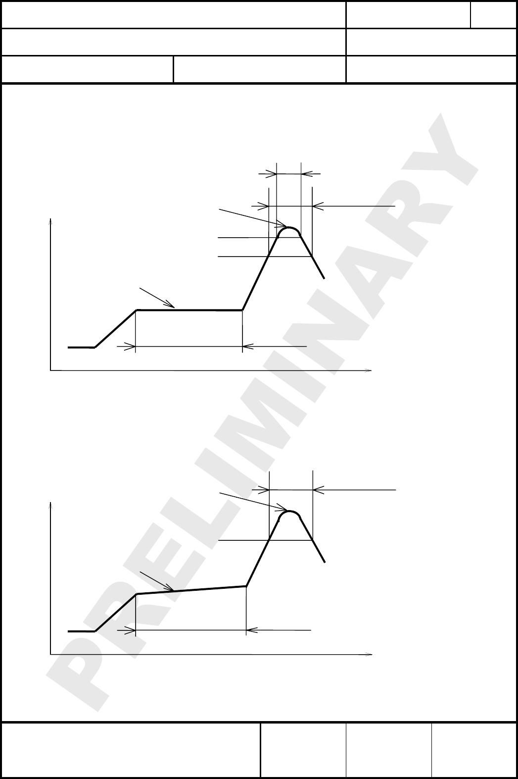
15. SOLDERING TEMPERATURE-TIME PROFILE (FOR REFLOW SOLDERING)
Temperatur-Zeit Profil für die Reflowlötung
15.1. FOR LEAD SOLDER
Recommended temp. profile
for reflow soldering
Tem
p
.
[
°C
]
Time [s]
235°C max.
220 ±5°C
200°C
150 ±10°C
90 ±30s
10
±
1s
30 +20/-10s
15.2. FOR LEADFREE SOLDER
Our used temp. profile
for reflow soldering
Temp.[°C]
Time [s]
230°C -250°C max.
220°C
150°C – 190°C
90 ±30s
30 +20/-10s
Reflow permissible cycle: 2
Opposite side reflow is prohibited due to module weight.
CLASSIFICATION
Einstufung
PRODUCT SPECIFICATION
Produktspezifikation
No.
DS-4555-2400-102
REV.
E
SUBJECT
Thema
MODEM FOR IEEE802.15.4 (ZIGBEE)
“ZigBee” Modem“ (IEEE802.15.4)
PAGE
Seite
13 of 30
CUSTOMER’S CODE
PAN4555
PANASONIC’S CODE
ENWC9A0xxxEF
DATE
Datum
20.08.2007
HIGH FREQUENCY PRODUCTS DIVISION
Module Business
PANASONIC ELECTRONIC DEVICES
EUROPE GmbH
APPROVED
genehmigt
CHECKED
geprüft
DESIGNED
erstellt
16. MODULE DIMENSION
Modulabmessungen
No. Item
Punkt
Dimension
Abmessung
Tolerance
Toleranz
Remark
Bemerkung
1 Width 12.20 ± 0.20
2 Lenght 16.40 ± 0.20
3 Height 2.20 ± 0.20 With case
17. FOOT PRINT OF THE MODULE
Lötpads vom Modul
All dimensions in mm.
The outer dimensions has a tolerance of ± 0.2mm.
0.3 mm
1.6 mm
2.2 mm
2.8 mm
3.4 mm
11.9 mm
12.2 mm
CLASSIFICATION
Einstufung
PRODUCT SPECIFICATION
Produktspezifikation
No.
DS-4555-2400-102
REV.
E
SUBJECT
Thema
MODEM FOR IEEE802.15.4 (ZIGBEE)
“ZigBee” Modem“ (IEEE802.15.4)
PAGE
Seite
14 of 30
CUSTOMER’S CODE
PAN4555
PANASONIC’S CODE
ENWC9A0xxxEF
DATE
Datum
20.08.2007
HIGH FREQUENCY PRODUCTS DIVISION
Module Business
PANASONIC ELECTRONIC DEVICES
EUROPE GmbH
APPROVED
genehmigt
CHECKED
geprüft
DESIGNED
erstellt
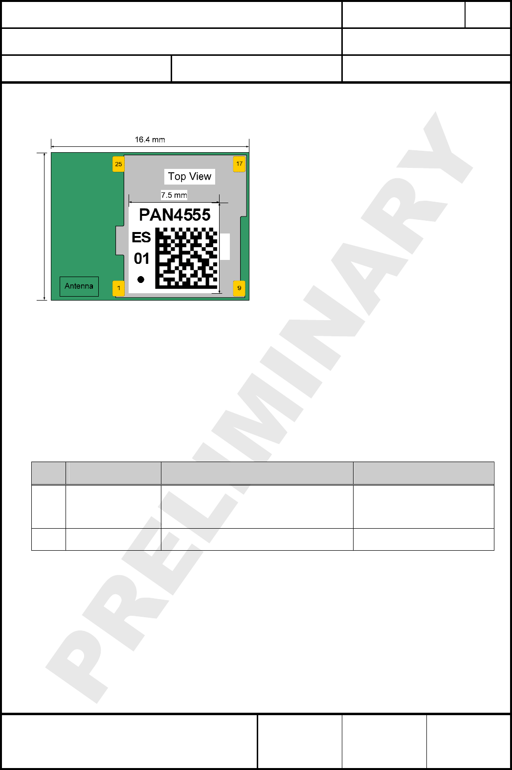
18. LABELING DRAWING
Kennzeichnung des Moduls durch Label
This label is suitable for reflow soldering and
designed for the engineering sample status.
Information in the 2D-Barcode are the date c
in the format Year-Month-Day [6 signs], serial
number [6 signs], ordering number [8 signs;
without ENW and F], the identifier for the
hardware release [2 signs, now 01] and the ES,
separated by a semicolon.
ode
ES stands for Engineering Samples, please
refer to chapter General Information.
In mass production status, the ES will be eliminated and replaced by a software identifier.
And will be also implemented at the last information in the 2D-Barcode.
The point on the label is the identifier for pin 1 of the module.
01 is the hardware revision.
7.5 mm
12.2 mm
19. MECHANICAL REQUIREMENTS
Mechanische Anforderungen
No. Item
Punkt
Limit
Grenzwerte
Condition
Bedingung
1 Solderability
Lötfähigkeit
More than 75% of the soldering area shall be
coated by solder
Mehr als 75% der Lötfläche soll mit Lötpaste
bedeckt sein.
Reflow soldering with
recommendable temperature
profile
2 Resistance to
soldering heat
It shall be satisfied electrical requirements and
not be mechanical damage Please refer to chapter 15.2.
CLASSIFICATION
Einstufung
PRODUCT SPECIFICATION
Produktspezifikation
No.
DS-4555-2400-102
REV.
E
SUBJECT
Thema
MODEM FOR IEEE802.15.4 (ZIGBEE)
“ZigBee” Modem“ (IEEE802.15.4)
PAGE
Seite
15 of 30
CUSTOMER’S CODE
PAN4555
PANASONIC’S CODE
ENWC9A0xxxEF
DATE
Datum
20.08.2007
HIGH FREQUENCY PRODUCTS DIVISION
Module Business
PANASONIC ELECTRONIC DEVICES
EUROPE GmbH
APPROVED
genehmigt
CHECKED
geprüft
DESIGNED
erstellt
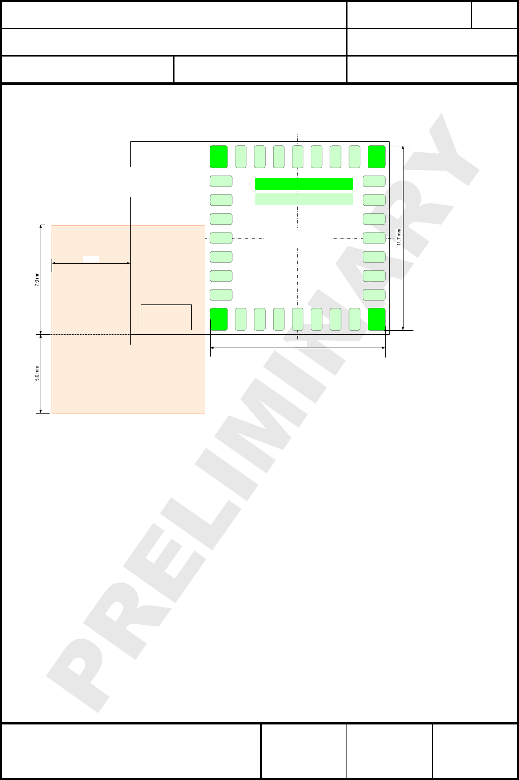
20. RECOMMENDED LAND PATTERN
Empfohlenes Land Pattern
Dimensions in mm.
The land pattern dimensions above can serve as a guidance, but this information is given
without any legal responsibility.
For your footprint, we recommend to use 50µm bigger size for the pads at each direction in
comparison to the module footprint, please refer to chapter 17. Foot Print of the Module.
For the solder paste screen please use the same as for the module, but slight different
measures and shapes of the solder paste screen cutouts might be optimum depending on your
soldering process, for example on the chosen solder paste screen thickness. The solder screen
thickness depends on your production standard, we recommend 120µm to 150µm.
IMPORTANT:
The bottom side of PAN4555 is fully coated, nevertheless no copper, such as through hole vias,
planes or tracks on your board component layer should be located below PAN4555 in order to
avoid short cuts. In cases where a track or through hole via has to be located under the module
it has to be kept away from PAN4555 bottom pads. The PN4555 multilayer pcb contains an
inner RF shielding plane, therefore no pcb shielding plane below the module is needed.
When using the antenna pad version and if your application allows, please place the antenna on
the edge of your carrier board.
14
15
16
13
12
11
10
28
27
Antenna
17
2
134 6789
5
Top View
25
11.1 mm
Pad 1 = 4 x 1.1mm x 1.4mm
Pad 2 = 28 x 0.7mm x 1.4mm
When using the ceramic antenna,
this minimum area is restriced,
means no ground, no line and in
general no metal, e.g. screws.
5.0 mm
In comparison to the module, we
recommend to use 50µm bigger
pad size to each direction!
24 23 22 20 19 1821
26
29
30
31
32

CLASSIFICATION
Einstufung
PRODUCT SPECIFICATION
Produktspezifikation
No.
DS-4555-2400-102
REV.
E
SUBJECT
Thema
MODEM FOR IEEE802.15.4 (ZIGBEE)
“ZigBee” Modem“ (IEEE802.15.4)
PAGE
Seite
16 of 30
CUSTOMER’S CODE
PAN4555
PANASONIC’S CODE
ENWC9A0xxxEF
DATE
Datum
20.08.2007
HIGH FREQUENCY PRODUCTS DIVISION
Module Business
PANASONIC ELECTRONIC DEVICES
EUROPE GmbH
APPROVED
genehmigt
CHECKED
geprüft
DESIGNED
erstellt
If you have any questions on these points, we are open to discuss your individual situation.

CLASSIFICATION
Einstufung
PRODUCT SPECIFICATION
Produktspezifikation
No.
DS-4555-2400-102
REV.
E
SUBJECT
Thema
MODEM FOR IEEE802.15.4 (ZIGBEE)
“ZigBee” Modem“ (IEEE802.15.4)
PAGE
Seite
17 of 30
CUSTOMER’S CODE
PAN4555
PANASONIC’S CODE
ENWC9A0xxxEF
DATE
Datum
20.08.2007
HIGH FREQUENCY PRODUCTS DIVISION
Module Business
PANASONIC ELECTRONIC DEVICES
EUROPE GmbH
APPROVED
genehmigt
CHECKED
geprüft
DESIGNED
erstellt
21. DEVELOPMENT OF APPLICATIONS WITH FREESCALE BEESTACKTM
Entwiclung von Applikationen mit Hilfe des BeeStacks von freescale
This chapter are copied from [8], please refer to this document to get more information.
PAN4555 is built around the MC13213 single package from Freescale Inc. which includes the
freescale ZigBee codebase BeeStackTM (downscaled versions of PAN4555 with MC1321x suited
for IEEE802.15.4 or SMAC only are available on demand as well).
The access to BeeStackPTMP is provided after registration and login at
http://www.freescale.com/zigbee . After login the BEEKITDOWNLOADPACKAGE.zip can be
downloaded. This package contains BeeStackPTMP , IEEE802.15.4 MAC and SMAC codebases.
For PAN4555 PHY testing using TestToolPTM P the download of the latest 1321xEVK package is
recommended.
After successful installation of Beekit on a PC open BeeKit. A ZigBee sample solution *.bksln
can be created in a few steps.
Important: Before a solution may be exported for PAN4555 the MC1321x target settings have
to be changed via the “User defined target editor”. The required changes are:
• Uncheck the “Use external Antenna Switch”
• Adjust the port settings depending on your application, the PAN4555 datasheet and for use
of the PAN4555 carrier board the pin list in chapter PAN4555 PINLIST at [8].
For importing, compiling and debugging of the BeeKitTM solution the Integrated Development
Environment (IDE) MetrowerksP
TM
PCodeWarrior from www.metrowerks.com is required.
As device flash programmer the USB HCS08/HCS12 Multilink from www.pemicro.com is
recommended.
Important: PAN4555 is a single RF port design with MC13213, refer also to AN3248.
The Freescale reference boards 13213-NCB and 13213-SRB are dual port designs,
software for these boards will not run.
The shipping of products which use ZigBeeTM technology requires a membership of the
ZigBeeTM Alliance (www.zigbee.org), at least as an adopter member, and is mandatory for the
ZigBeeTM product certification procedure and use of the ZigBeeTM Logo.
The prices and fees as known from today are as follows:
• IDE CodeWarrior order number CWS-H08-C64K-CX from www.metrowerks.com :
US$ 995,-.
• USB HCS08/HCS12 Multilink (www.pemicro.com), orderable at www.freescale.com/zigbee
with the ID USBMULTILINKBDM: US$ 99,-
• BeeStackTM: The support fee after a 30 days period free of charge required by Freescale
CLASSIFICATION
Einstufung
PRODUCT SPECIFICATION
Produktspezifikation
No.
DS-4555-2400-102
REV.
E
SUBJECT
Thema
MODEM FOR IEEE802.15.4 (ZIGBEE)
“ZigBee” Modem“ (IEEE802.15.4)
PAGE
Seite
18 of 30
CUSTOMER’S CODE
PAN4555
PANASONIC’S CODE
ENWC9A0xxxEF
DATE
Datum
20.08.2007
HIGH FREQUENCY PRODUCTS DIVISION
Module Business
PANASONIC ELECTRONIC DEVICES
EUROPE GmbH
APPROVED
genehmigt
CHECKED
geprüft
DESIGNED
erstellt
Inc. is US$ 500,-.
• Companies selling products using ZigBeeTM technology have to be a member of the
ZigBeeTM Alliance (www.zigbee.org). The minimum fee per year for a membership as
adopter is US$ 3500,-.
• For adopter members the fee for listing the first product at (www.zigbee.org) is US$ 1000,-.
• The cost of a ZigBeeTM product certification at a test house (TÜV Rheinland) ranges from
approximately US$ 4000,- to US$ 8000,-, depending on the implemented software.
22. RELIABILITY TESTS
Zuverlässigkeitstests
The measurement should be done after exposed to room temperature and humidity for 1hour.
Die Messungen sollten erst nach einer Stunde Lagerung unter normalen Bedingungen erfolgen.
No. Item
Punkt
Limit
Grenzwerte
Condition
Bedingung
1 Vibration test Electrical parameter should be
in specification
a) Freq.:10~50Hz,Amplitude:1.5mm
a) 20min. / cycle,1hrs. each of XYZ axis
b) Freq.:30~100Hz, 6G
b) 20min. / cycle,1hrs. each of XYZ axis
2 Shock test the same as the above Dropped onto hard wood from height of 50cm for
3 times
3 Heat cycle test the same as the above -40°C for 30min. and +85°C for 30min.;
each temperature 300 cycles
4 Moisture test the same as the above +60°C, 90% RH, 300h
5 Low temp. test the same as the above -40°C, 300h
6 High temp. test the same as the above +85°C, 300h
23. CAUTIONS
Warnungen
Failure to do so may result in degrading of the product’s functions and damage to the product.
23.1. NOTES OF DESIGN
Designhinweise
(1) Please follow the condition written in this specification, especially the control
signals of this module.
(2) The supply voltage has to be free of ac ripple voltage, as for example from a
battery or a low noise regulator output. For noisy supply voltages provide a
decoupling circuit as for example a ferrite in series connection and a blocking
capacitor to ground of at least 47uF directly at the module.
(3) This product should not be stressed when installed.
(4) Heat is the major cause of shortening the life of these products. Please keep this
product away from heat.
Avoid assembly and use of the target equipment in conditions where the

CLASSIFICATION
Einstufung
PRODUCT SPECIFICATION
Produktspezifikation
No.
DS-4555-2400-102
REV.
E
SUBJECT
Thema
MODEM FOR IEEE802.15.4 (ZIGBEE)
“ZigBee” Modem“ (IEEE802.15.4)
PAGE
Seite
19 of 30
CUSTOMER’S CODE
PAN4555
PANASONIC’S CODE
ENWC9A0xxxEF
DATE
Datum
20.08.2007
HIGH FREQUENCY PRODUCTS DIVISION
Module Business
PANASONIC ELECTRONIC DEVICES
EUROPE GmbH
APPROVED
genehmigt
CHECKED
geprüft
DESIGNED
erstellt
products' temperature may exceed the maximum allowable.
(5) The supply voltage should not be exceeding or reverse, and should not carry
noise and spike.
(6) Please keep this product away from other high frequency circuits.
23.2. NOTES OF INSTALLATION
Verarbeitungshinweise
(1) Reflow soldering is possible for twice on the condition in chapter 15.
Please set up the temperature at the soldering portion of this product according
to this reflow profile.
(2) Carefully position the products so that their heat will not burn into printed circuit
boards or affect the other components that are susceptible to heat.
(3) Carefully locate these products so that their temperatures will not increase due
to the effects of heat generated by neighboring components.
(4) If a vinyl-covered wire comes into contact with the products, then the cover will
melt and generate toxic gas, damaging the insulation. Never allow contact
between the cover and these products to occur.
(5) This product should not be stressed or vibrated when reflowed.
(6) Please keep the following conditions when you install this product for reparation
by hand soldering.
(7) Please do not wash this product.
(8) Please refer to the recommended pattern when designing a board.
(9) Pressing on parts of the metal cover or fastening objects to the metal cover is
not allowed.
23.3. NOTES OF USAGE CONDITIONS
Benutzerhinweise
(1) Please take measure against static electricity.
If pulses or other transient loads (a large load applied in a short time) are applied
to the products, then before use, check and evaluate their operation when
assembled on your products.
(2) Please do not use the fallen product.
(3) Please do not put on damage and dirt to the pin , and don't touch the electric
components.
(4) Please follow the condition written in the ratings , about the power supply
instruments applied to this product.
(5) Electrode peeling strength: Do not add pressure of more than 4.9N when
soldered on PCB
(6) Pressing on parts of the metal cover or fastening objects to the metal cover is
not allowed.
(7) These products are intended for general purpose and standard use in general
electronic equipment, such as home appliances, office equipment, information
and communication equipment.

CLASSIFICATION
Einstufung
PRODUCT SPECIFICATION
Produktspezifikation
No.
DS-4555-2400-102
REV.
E
SUBJECT
Thema
MODEM FOR IEEE802.15.4 (ZIGBEE)
“ZigBee” Modem“ (IEEE802.15.4)
PAGE
Seite
20 of 30
CUSTOMER’S CODE
PAN4555
PANASONIC’S CODE
ENWC9A0xxxEF
DATE
Datum
20.08.2007
HIGH FREQUENCY PRODUCTS DIVISION
Module Business
PANASONIC ELECTRONIC DEVICES
EUROPE GmbH
APPROVED
genehmigt
CHECKED
geprüft
DESIGNED
erstellt
23.4. NOTES OF STORAGE
Lagerhinweise
(1) The module may not be stressed mechanically during storage.
(2) Do not store these products in the following conditions or the performance
characteristics of the product, such as RF performance will be adversely
affected:
• Storage in salty air or in an environment with a high concentration of corrosive
gas, such as Cl2, H2S, NH3, SO2, or NOX
• Storage in direct sunlight
• Storage in an environment where the temperature may be outside the range of
5°C to 35°C range, or where the humidity may be outside the 45 to 85% range.
• Storage of the products for more than one year after the date of delivery at your
company if all the above conditions (1) to (3) have been avoided
(3) Storage period: Please check the adhesive strength of the embossed tape and
soldering after 6 months of storage.
(4) Please keep this product away from water, poisonous gas and corrosive gas.
(5) This product should not be stressed or shocked when transported.
(6) Please follow the specification when piling up the packed crate ( max. 10).
23.5. CAUTIONS FOR SAFETY
Sicherheitshinweise
These specifications are intended to preserve the quality assurance of products as
individual components.
Before use, check and evaluate their operation when mounted on your products. Abide by
these specifications, without deviation when using the products.These products may short-
circuit. If electrical shocks, smoke, fire, and/or accidents involving human life are
anticipated when a short circuit occurs, then at least, provide the following failsafe
functions, as a minimum.
(1) Ensure the safety of the whole system by installing a protection circuit and a
protection device.
(2) Ensure the safety of the whole system by installing a redundant circuit or
another system to prevent a single fault causing an unsafe status.
23.6. OTHER CAUTIONS
Weitere Hinweise
(1) This specification sheet is copyrighted. Please do not open it to the third party.
(2) Please do not use this product of our company for another purpose.
(3) Be sure to provide an appropriate fail-safe function on your product to prevent a
second damage that may be caused by the abnormal function or the failure of
our product.
(4) This product has not been manufactured with any ozone chemical controlled
under the Montreal Protocol.
(5) These products are not intended for other uses, other than under the special
conditions shown below. Before using these products under such special
conditions, check their performance and reliability under the said special

CLASSIFICATION
Einstufung
PRODUCT SPECIFICATION
Produktspezifikation
No.
DS-4555-2400-102
REV.
E
SUBJECT
Thema
MODEM FOR IEEE802.15.4 (ZIGBEE)
“ZigBee” Modem“ (IEEE802.15.4)
PAGE
Seite
21 of 30
CUSTOMER’S CODE
PAN4555
PANASONIC’S CODE
ENWC9A0xxxEF
DATE
Datum
20.08.2007
HIGH FREQUENCY PRODUCTS DIVISION
Module Business
PANASONIC ELECTRONIC DEVICES
EUROPE GmbH
APPROVED
genehmigt
CHECKED
geprüft
DESIGNED
erstellt
conditions carefully to determine whether or not they can be used in such a
manner.
• In liquid, such as water, salt water, oil, alkali, or organic solvent, or in places
where liquid may splash.
• In direct sunlight, outdoors, or in a dusty environment
• In an environment where condensation occurs.
• In an environment with a high concentration of harmful gas (e.g. salty air,
HCl, Cl2, SO2, H2S, NH3, and NOX)
(6) If an abnormal voltage is applied due to a problem occurring in other
components or circuits, replace these products with new products because they
may not be able to provide normal performance even if their electronic
characteristics and appearances appear satisfactory.
(7) When you have any question or uncertainty , both of you and Panasonic
sincerely cope with it.
CLASSIFICATION
Einstufung
PRODUCT SPECIFICATION
Produktspezifikation
No.
DS-4555-2400-102
REV.
E
SUBJECT
Thema
MODEM FOR IEEE802.15.4 (ZIGBEE)
“ZigBee” Modem“ (IEEE802.15.4)
PAGE
Seite
22 of 30
CUSTOMER’S CODE
PAN4555
PANASONIC’S CODE
ENWC9A0xxxEF
DATE
Datum
20.08.2007
HIGH FREQUENCY PRODUCTS DIVISION
Module Business
PANASONIC ELECTRONIC DEVICES
EUROPE GmbH
APPROVED
genehmigt
CHECKED
geprüft
DESIGNED
erstellt
24. PACKAGING
Verpackung
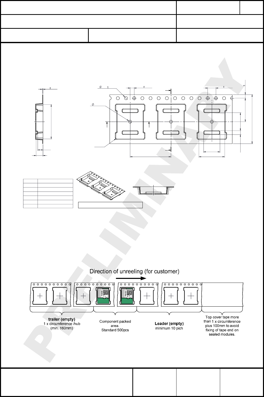
24.1. TAPE DIMENSION
This package will be available latest as the mass production status are confirmed.
1.55 0.05
Do
4.0
0.1(II)
Po
W
2.0
0.1(I)
P2
1.75
0.1
E1
1.5
MIN
D1
F(III)
Ao
8.0
REF
8.8
REF
1.9
REF
P1
Y
Y
XX
R0.5
TYPICAL
0.30 0.05
T
Ko
K1
Bo
SECTION Y-Y
SECTION X-X
Measured from centreline of sprocket hole
to centreline of pocket.
Cumulative tolerance of 10 sprocket
holes is± 0.20 .
Measured from centreline of sprocket
hole to centreline of pocket.
(I)
(II)
(III)
(IV) Other material available.
ALL DIMENSIONS IN MILLIMETRES UNLESS OTHERWISE STA
T
W
F
P
1
+/- 0.1
+/- 0.1
+/- 0.3
11.50
20.00
24.00
+/- 0.13.40
Ao
12.60 +/- 0.1
Ko
Bo
16.80 +/- 0.1
Estimated max. length : 60
meter/22B3 reel
Forming format : Flatbed
K
2.60
1
+/- 0.1
24.2. PACKING IN TAPE
Empty hollow in component packed area shall be less than two per reel and those hollows
shall not be consecutive.
Top cover tape shall not be found on reel holes and shall not stick out from reel.
CLASSIFICATION
Einstufung
PRODUCT SPECIFICATION
Produktspezifikation
No.
DS-4555-2400-102
REV.
E
SUBJECT
Thema
MODEM FOR IEEE802.15.4 (ZIGBEE)
“ZigBee” Modem“ (IEEE802.15.4)
PAGE
Seite
23 of 30
CUSTOMER’S CODE
PAN4555
PANASONIC’S CODE
ENWC9A0xxxEF
DATE
Datum
20.08.2007
HIGH FREQUENCY PRODUCTS DIVISION
Module Business
PANASONIC ELECTRONIC DEVICES
EUROPE GmbH
APPROVED
genehmigt
CHECKED
geprüft
DESIGNED
erstellt
24.3
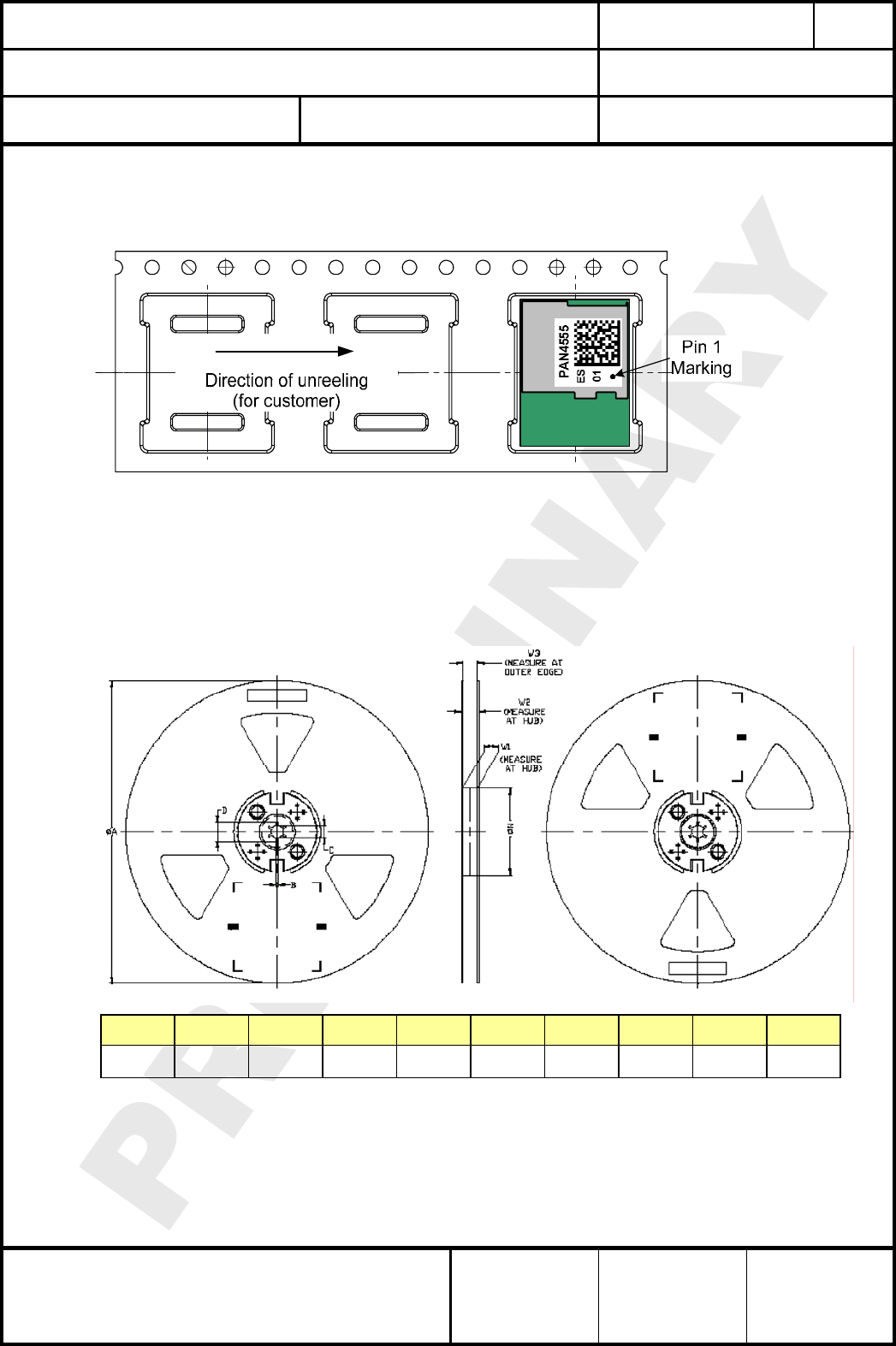
lease refer also to chapter 18. Labeling Drawing
roduction status are confirmed.
24.4. REEL DIMENSION
. COMPONENT DIRECTION
Komponentenanordnung
P
This package will be available latest as the mass p
A B D N W2
MAX MIN MIN MAX Assembly
±1.0
13
+0.5
25.0
+2.0
24.4
+3.0
-0.2 -0.0 -0.5
*Latch (2PC)All dimensions in millimeters unless otherwise stated
Method
24mm 330.0 1.5 20.2 100.0 30.4 *Latch
TAPE SIZE C W1 W3
CLASSIFICATION
Einstufung
PRODUCT SPECIFICATION
Produktspezifikation
No.
DS-4555-2400-102
REV.
E
SUBJECT
Thema
MODEM FOR IEEE802.15.4 (ZIGBEE)
“ZigBee” Modem“ (IEEE802.15.4)
PAGE
Seite
24 of 30
CUSTOMER’S CODE
PAN4555
PANASONIC’S CODE
ENWC9A0xxxEF
DATE
Datum
20.08.2007
HIGH FREQUENCY PRODUCTS DIVISION
Module Business
PANASONIC ELECTRONIC DEVICES
EUROPE GmbH
APPROVED
genehmigt
CHECKED
geprüft
DESIGNED
erstellt
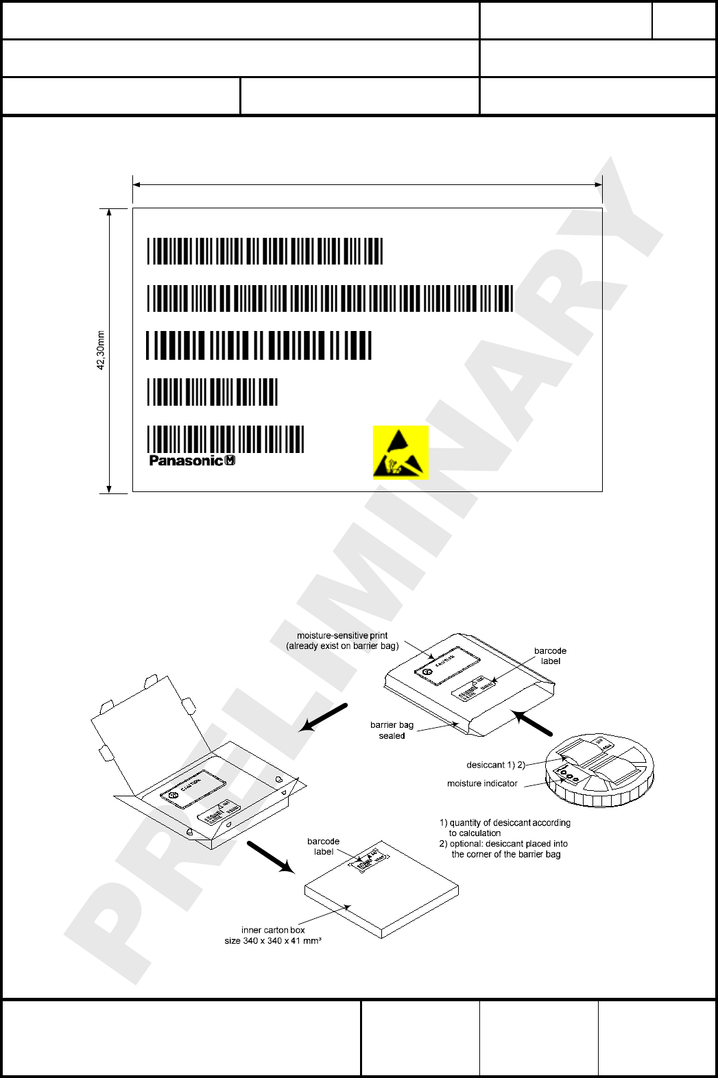
24.5. LABEL FOR PACKAGE
The label must be stick 3 times, reel, barrier bag and inner carton box.
70,00mm
(P)P/N
P
A
N4555
(1P)PO No.
ENWC9A08A3EF
Descr iption
ES Sample
ES Status
(Q)QTY
500
MSL tbd
Tmax tbd
(D)DATE CODE
7419
[[G]]
MADE IN
GERMANY
24.6. TOTAL PACKING HANDLING
CLASSIFICATION
Einstufung
PRODUCT SPECIFICATION
Produktspezifikation
No.
DS-4555-2400-102
REV.
E
SUBJECT
Thema
MODEM FOR IEEE802.15.4 (ZIGBEE)
“ZigBee” Modem“ (IEEE802.15.4)
PAGE
Seite
25 of 30
CUSTOMER’S CODE
PAN4555
PANASONIC’S CODE
ENWC9A0xxxEF
DATE
Datum
20.08.2007
HIGH FREQUENCY PRODUCTS DIVISION
Module Business
PANASONIC ELECTRONIC DEVICES
EUROPE GmbH
APPROVED
genehmigt
CHECKED
geprüft
DESIGNED
erstellt
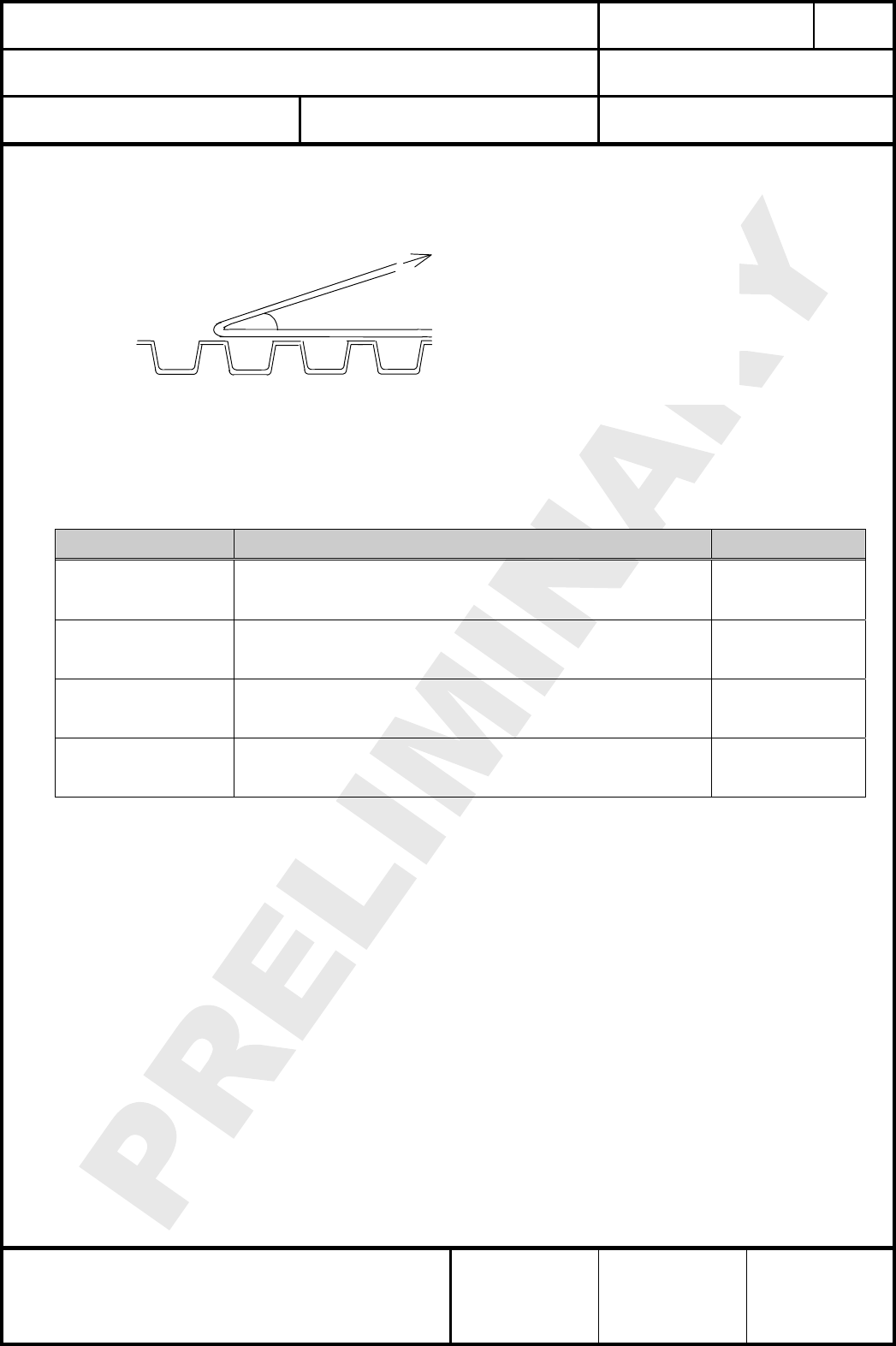
24.7. COVER TAPE REEL STRENGTH
Force direction
Speed = 300mm/min.
Cover tape reel strength
=0.098~0.68N (10~70g)
θ= 10deg
25. ORDERING INFORMATION
Bestellinformationen
Ordering part number Description MOQ (1)
ENWCZA08A3EF (2)
Engineering Sample ZigBee ready
PAN4555, 2.4GHz ZigBee ready with Ceramic Antenna
60kBit Flash Memory
1
ENWCZA09N4EF (2)
Engineering Sample ZigBee ready
PAN4555, 2.4GHz ZigBee ready with RF out on a SMD pad
60kBit Flash Memory
1
ENWC9A08A3EF (3)
Mass Production Sample ZigBee ready
PAN4555, 2.4GHz ZigBee ready with Ceramic Antenna
60kBit Flash Memory
500 (4)
ENWC9A09N4EF (3)
Mass Production Sample ZigBee ready
PAN4555, 2.4GHz ZigBee ready with RF out on a SMD pad
60kBit Flash Memory
500 (4)
Note:
(1) Minimum order quantity.
(2) The “Z” in the ordering part number, refers to the engineering sample status. After mass production
the “Z” will be changed to the “9”.
(3) Could only be ordered, if we released the mass production status.
If we finishing, this document will change from PRELIMINARY to RELEASE also the revision status
will move from alphabetic numbering to 1.0.
(4) On special agreement we can also deliver in lower quantity!
CLASSIFICATION
Einstufung
PRODUCT SPECIFICATION
Produktspezifikation
No.
DS-4555-2400-102
REV.
E
SUBJECT
Thema
MODEM FOR IEEE802.15.4 (ZIGBEE)
“ZigBee” Modem“ (IEEE802.15.4)
PAGE
Seite
26 of 30
CUSTOMER’S CODE
PAN4555
PANASONIC’S CODE
ENWC9A0xxxEF
DATE
Datum
20.08.2007
HIGH FREQUENCY PRODUCTS DIVISION
Module Business
PANASONIC ELECTRONIC DEVICES
EUROPE GmbH
APPROVED
genehmigt
CHECKED
geprüft
DESIGNED
erstellt
26. ROHS DECLARATION
RoHS-Erklärung
Declaration of environmental compatibility for supplied products:
Hereby we declare to our best present knowledge based on declaration of our suppliers that this
product do not contain by now the following substances which are banned by Directive
2002/95/EC (RoHS) or if contain a maximum concentration of 0,1% by weight in homogeneous
materials for
• Lead and lead compounds
• Mercury and mercury compounds
• Chromium (VI)
• PBB (polybrominated biphenyl) category
• PBDE (polybrominated biphenyl ether) category
And a maximum concentration of 0,01% by weight in homogeneous materials for
• Cadmium and cadmium compounds
27. DATA SHEET STATUS
Datenblatt Status
This data sheet contains data from the PRELIMINARY specification. Supplementary data will be
published at a later date. Panasonic Electronic Devices Europe GmbH reserves the right to
change the specification without notice, in order to improve the design and supply the best
possible product.
Please consult the most recently issued data sheet before initiating or completing a design.
If there is an update, please download under: PAN4555 Latest Data Sheet!
28. REGULATORY INFORMATION
28.1. FCC NOTICE
The device PAN4555, including the ceramic antenna (ENWC9A08A3EF) and also the SMD
type (ENWC9A09N4EF), including with the antennas, which are listed in 28.5, complies
with Part 15 of the FCC Rules. The device meets the requirements for modular transmitter
approval as detailed in FCC public Notice DA00-1407.transmitter
Operation is subject to the following two conditions: (1) This device may not cause harmful
interference, and (2) This device must accept any interference received, including
interference that may cause undesired operation.
CLASSIFICATION
Einstufung
PRODUCT SPECIFICATION
Produktspezifikation
No.
DS-4555-2400-102
REV.
E
SUBJECT
Thema
MODEM FOR IEEE802.15.4 (ZIGBEE)
“ZigBee” Modem“ (IEEE802.15.4)
PAGE
Seite
27 of 30
CUSTOMER’S CODE
PAN4555
PANASONIC’S CODE
ENWC9A0xxxEF
DATE
Datum
20.08.2007
HIGH FREQUENCY PRODUCTS DIVISION
Module Business
PANASONIC ELECTRONIC DEVICES
EUROPE GmbH
APPROVED
genehmigt
CHECKED
geprüft
DESIGNED
erstellt
28.2. CAUTION
The FCC requires the user to be notified that any changes or modifications made to this
device that are not expressly approved by Panasonic Electronic Devices Europe GmbH
may void the user's authority to operate the equipment.
This equipment has been tested and found to comply with the limits for a Class B digital
device, pursuant to Part 15 of the FCC Rules. These limits are designed to provide
reasonable protection against harmful interference in a residential installation. This
equipment generates, uses and can radiate radio frequency energy and, if not installed and
used in accordance with the instructions, may cause harmful interference to radio
communications. However, there is no guarantee that interference will not occur in a
particular installation. If this equipment does cause harmful interference to radio or
television reception, which can be determined by turning the equipment off and on, the user
is encouraged to try to correct the interference by one or more of the following measures:
• Reorient or relocate the receiving antenna.
• Increase the separation between the equipment and receiver.
• Connect the equipment into an outlet on a circuit different from that to which the
receiver is connected.
• Consult the dealer or an experienced radio/TV technician for help
28.3. LABELING REQUIREMENTS
The Original Equipment Manufacturer (OEM) must ensure that FCC labeling requirements
are met. This includes a clearly visible label on the outside of the OEM enclosure
specifying the appropriate Panasonic FCC identifier for this product as well as the FCC
Notice above. The FCC identifier are FCC ID: T7VPAN4555. This FCC identifier is valid for
both versions, for details, please see the chapter 25. Ordering Information.
Due to the size limitation, the EUT could not be labelled with the FCC ID: T7VPAN4555.
However the FCC ID can be read from the UART of the device with the
AT command “FCC ID ?” and the module will answer with FCC ID: T7VPAN4555.
In any case end product must be labelled exterior with "Contains FCC ID: T7VPAN4555"
28.4. ANTENNA WARNING
The related part number for this device is ENWC9A09N4EF (PAN4555 with SMD pad). For
details, please see the chapter 25. Ordering Information. This device are tested with a
standard SMA connector and with the antennas listed below. When integrated in the OEMs
product, these fixed antennas require installation preventing end-users from replacing them
with non-approved antennas. Any antenna not in the following table must be tested to
comply with FCC Section 15.203 for unique antenna connectors and Section 15.247 for
emissions. The FCC identifier for this device with the antenna listed in item 1 are the same
(FCC ID: T7VPAN4555).
CLASSIFICATION
Einstufung
PRODUCT SPECIFICATION
Produktspezifikation
No.
DS-4555-2400-102
REV.
E
SUBJECT
Thema
MODEM FOR IEEE802.15.4 (ZIGBEE)
“ZigBee” Modem“ (IEEE802.15.4)
PAGE
Seite
28 of 30
CUSTOMER’S CODE
PAN4555
PANASONIC’S CODE
ENWC9A0xxxEF
DATE
Datum
20.08.2007
HIGH FREQUENCY PRODUCTS DIVISION
Module Business
PANASONIC ELECTRONIC DEVICES
EUROPE GmbH
APPROVED
genehmigt
CHECKED
geprüft
DESIGNED
erstellt
28.5. APPROVED ANTENNA LIST
Note: We are able to qualify your antenna and will add to this list as that process is completed.
Item Part Number Manufacturer Frequency Band Type Gain (dBi)
1 BKR2400 Embedded Antenna Design Ltd. 2.4GHz ½ Wave Dipole +2
2
28.6. RF EXPOSURE PAN4555
To comply with FCC RF Exposure requirements, the Original Equipment Manufacturer
(OEM) must ensure that the approved antenna in the previous table must be installed.
The preceding statement must be included as a CAUTION statement in manuals for
products operating with the approved antennas in the previous table to alert users on FCC
RF Exposure compliance.
Any notification to the end user of installation or removal instructions about the integrated
radio module is not allowed.
The radiated output power of PAN4555 with mounted ceramic antenna
(FCC ID: T7VPAN4555) is far below the FCC radio frequency exposure limits.
Nevertheless, the PAN4555 shall be used in such a manner that the potential for human
contact during normal operation is minimized.
End users may not be provided with the module installation instructions. OEM integrators
and end users must be provided with transmitter operating conditions for satisfying RF
exposure compliance.

CLASSIFICATION
Einstufung
PRODUCT SPECIFICATION
Produktspezifikation
No.
DS-4555-2400-102
REV.
E
SUBJECT
Thema
MODEM FOR IEEE802.15.4 (ZIGBEE)
“ZigBee” Modem“ (IEEE802.15.4)
PAGE
Seite
29 of 30
CUSTOMER’S CODE
PAN4555
PANASONIC’S CODE
ENWC9A0xxxEF
DATE
Datum
20.08.2007
HIGH FREQUENCY PRODUCTS DIVISION
Module Business
PANASONIC ELECTRONIC DEVICES
EUROPE GmbH
APPROVED
genehmigt
CHECKED
geprüft
DESIGNED
erstellt
29. RELATED DOCUMENTS
Mitgeltende Dokumente
For an update, please search in the suitable homepage.
[1] IEEE Standard 802.15.4 –2003 Wireless Medium Access Control (MAC) and Physical Layer
(PHY) Specifications for Low-Rate Wireless Personal Area Networks (LR-WPANs)
[2] Technical Data MC1321x Document Number: MC1321x
Rev. 1.1, 03/2007 Freescale Semiconductor
[3] MC1321x Reference Manual Document Number: MC1321xRM
Rev. 1.1, 10/2006 Freescale Semiconductor
[4] Handling MAC Address erasure, AN2825, Rev. 0.0 10/2004, Freescale Semiconductor
[5] 802154MPSUG 802.15.4 MAC/PHY Software User´s Guide, Rev 1.1, Freescale
Semiconductor
[6] 802154EBRM.pdf 802.15.4 / ZigBee Embedded Bootloader Reference Manual Rev. 0.0
09/2004
[7] AN2771 ZigBee/802.15.4 PHY Protocol Test Client (PTC) Rev. 0.0 Freescale Semiconductor
[8] Manual to the Evaluation Kit from Panasonic
Downloadable under: www.pedeu.panasonic.de.

CLASSIFICATION
Einstufung
PRODUCT SPECIFICATION
Produktspezifikation
No.
DS-4555-2400-102
REV.
E
SUBJECT
Thema
MODEM FOR IEEE802.15.4 (ZIGBEE)
“ZigBee” Modem“ (IEEE802.15.4)
PAGE
Seite
30 of 30
CUSTOMER’S CODE
PAN4555
PANASONIC’S CODE
ENWC9A0xxxEF
DATE
Datum
20.08.2007
HIGH FREQUENCY PRODUCTS DIVISION
Module Business
PANASONIC ELECTRONIC DEVICES
EUROPE GmbH
APPROVED
genehmigt
CHECKED
geprüft
DESIGNED
erstellt
30. GENERAL INFORMATION
Allgemeine Informationen
© Panasonic Electronic Devices Europe GmbH 2007.
All rights reserved.
This product description does not lodge the claim to be complete and free of mistakes.
Please contact the related product manager in every case.
If we deliver samples to the customer, these samples have the status Engineering Samples.
This means, the design of this product is not yet concluded. Engineering Samples may be
partially or fully functional, and there may be differences to be published Data Sheet.
Engineering Samples are not qualified and are not to be used for reliability testing or series
production.
Disclaimer:
Customer acknowledges that samples may deviate from the Data Sheet and may bear defects
due to their status of development and the lack of qualification mentioned above.
Panasonic Electronic Devices Europe GmbH rejects any liability or product warranty for
Engineering Samples. In particular, Panasonic Electronic Devices Europe GmbH disclaims
liability for damages caused by
• the use of the Engineering Sample other than for Evaluation Purposes, particularly the
installation or integration in an other product to be sold by Customer,
• deviation or lapse in function of Engineering Sample,
• improper use of Engineering Samples.
Panasonic Electronic Devices Europe GmbH disclaimes any liability for consequential and
incidental damages. In case of any questions, please contact your local sales partner or the
related product manager.
31. LIFE SUPPORT POLICY
Politik für Lebenserhaltungssysteme
This Panasonic Electronic Devices Europe GmbH product is not designed for use in life
support appliances, devices, or systems where malfunction can reasonably be expected to
result in a significant personal injury to the user, or as a critical component in any life support
device or system whose failure to perform can be reasonably expected to cause the failure of
the life support device or system, or to affect its safety or effectiveness. Customers using or
selling these products for use in such applications do so at their own risk and agree to fully
indemnify Panasonic Electronic Devices Europe GmbH for any damages resulting.