Panasonic Devices Europe PAN8550 Z-Wave Module PAN8550 User Manual TABLE OF CONTENTS
Panasonic Industrial Devices Europe GmbH Z-Wave Module PAN8550 TABLE OF CONTENTS
UserManual.wiki
>
Panasonic Devices Europe
>
PAN8550 User Manual
Manual
Navigation menu
Upload a User Manual
Namespaces
Wiki Guide
HTML
PDF
Info
Views
User Manual
Discussion / Help
Navigation
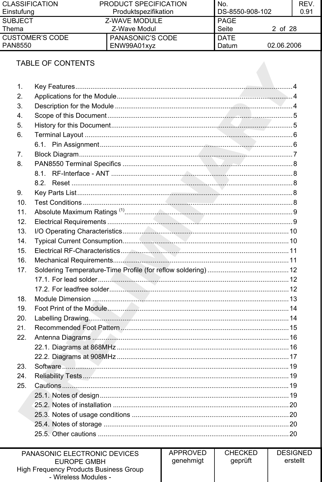
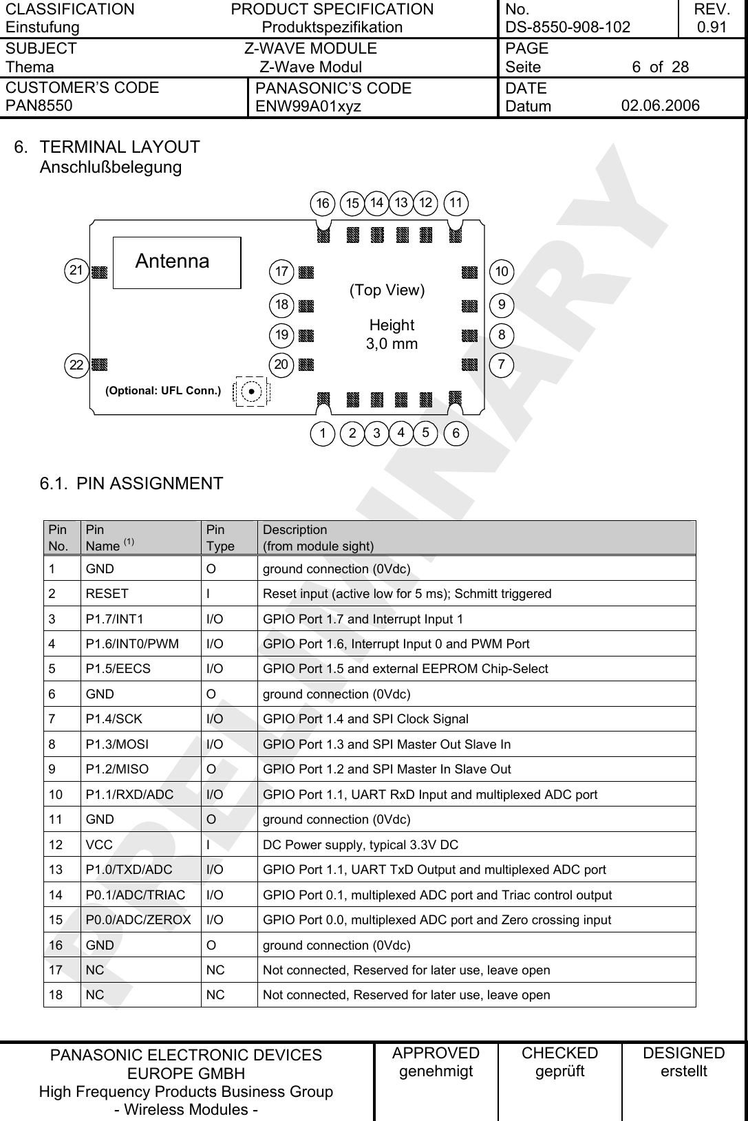
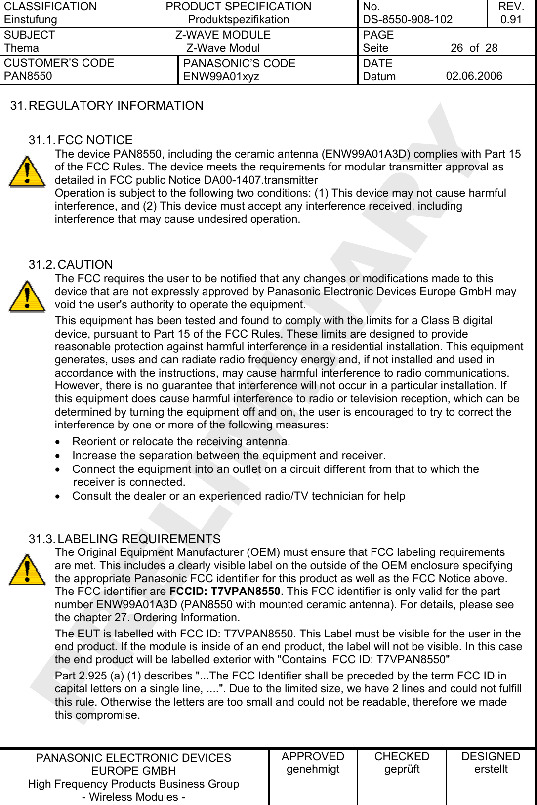
![CLASSIFICATION Einstufung PRODUCT SPECIFICATION Produktspezifikation No. DS-8550-908-102 REV. 0.91 SUBJECT Thema Z-WAVE MODULE Z-Wave Modul PAGE Seite 8 of 28 CUSTOMER’S CODE PAN8550 PANASONIC’S CODE ENW99A01xyz DATE Datum 02.06.2006 PANASONIC ELECTRONIC DEVICES EUROPE GMBH High Frequency Products Business Group - Wireless Modules - APPROVED genehmigt CHECKED geprüft DESIGNED erstellt 8. PAN8550 TERMINAL SPECIFICS PAN8550 Interfacebeschreibungen 8.1. RF-INTERFACE - ANT The PAN8550 presents a 50 impedance on the plug connector. If you need additional antenna support please e-mail to wireless@ecom.panasonic.de or use the PAN8550 with integrated ceramic antenna. The details please refer to chapter 27. 8.2. RESET The RESET pin is an active low input that can be used to perform a full reset of the device from an external signal. This pin does not contain an internal pull-up, so it should be pulled-up externally if not used. 9. KEY PARTS LIST Liste der Schlüsselkomponenten Part Name Teilenummer Material Material P.W.Board Leiterplatte Glass cloth epoxide resin with gold plating FR4 mit Goldauflage Casing Deckel Material: CuNi18ZN20, thickness 0.2mm Material: Weißblech 0,2mm Dicke IC part name IC Name ZW0201 (Zensysy Inc www.zen-sysy.com) All information are based on [1] chapter 30 Antenna name Antennenname 0920AT50A080 (Johanson www.johanson.com) All information are based on [2] chapter 30 Connector name Steckername U.FL-R-SMT(10) No. 331-0471-0-10 (Hirose www.hirose.com) All information are based on [3] chapter 30 10. TEST CONDITIONS Meßbedingungen Measurements shall be made under room temperature and humidity unless otherwise specified. Messungen unter normalen Bedingungen, Abweichungen sind gesondert notiert. Temperature 25 ± 10°C Humidity 40 to 85%RH Temperatur 25 ± 10°C Luftfeuchtigkeit 40 to 85%RH](https://usermanual.wiki/Panasonic-Devices-Europe/PAN8550/User-Guide-666650-Page-8.png)
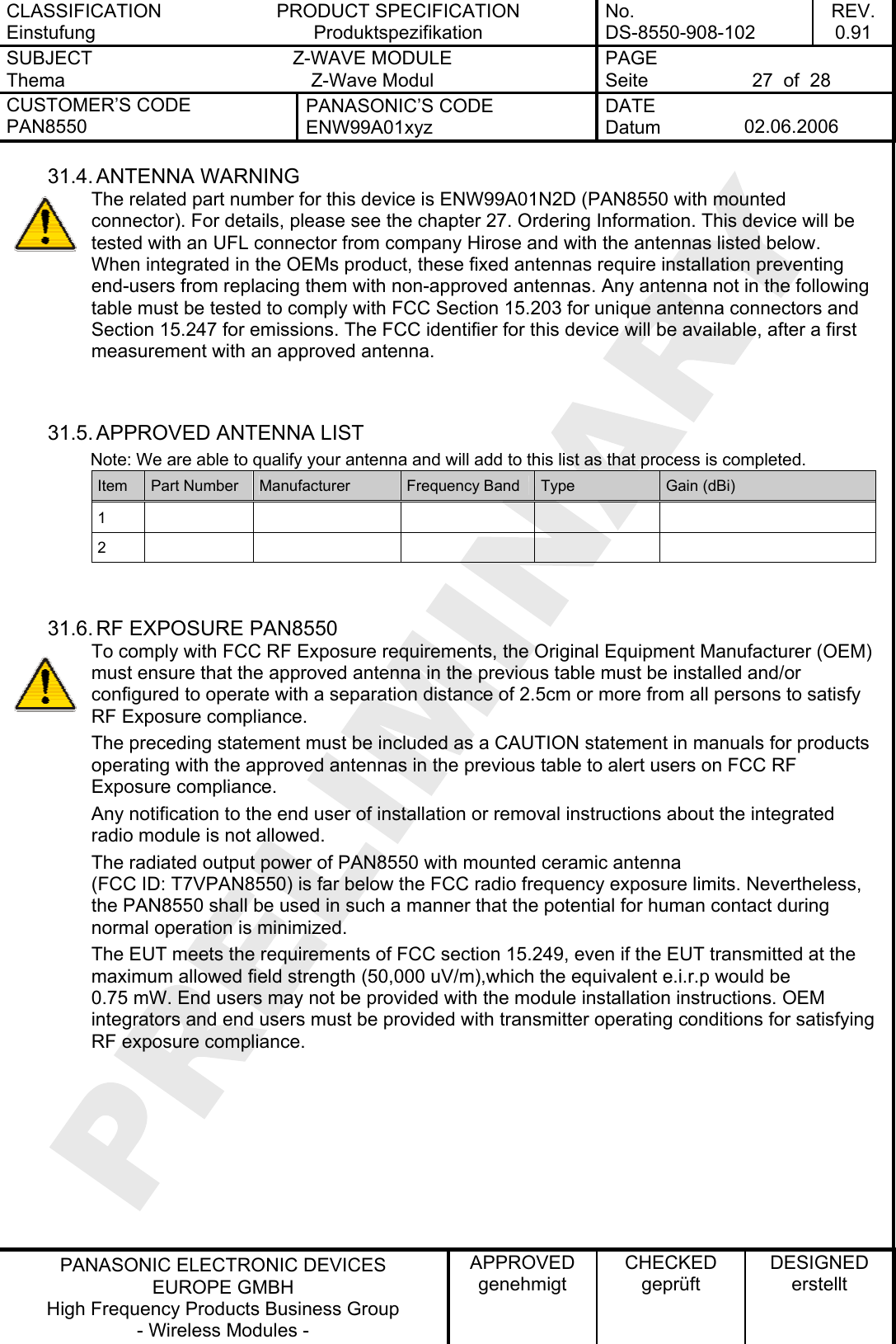
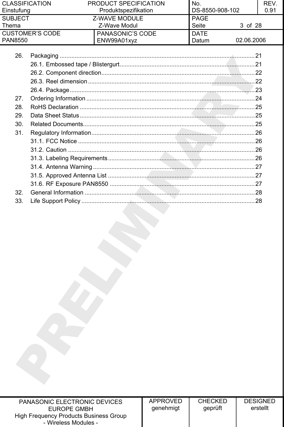
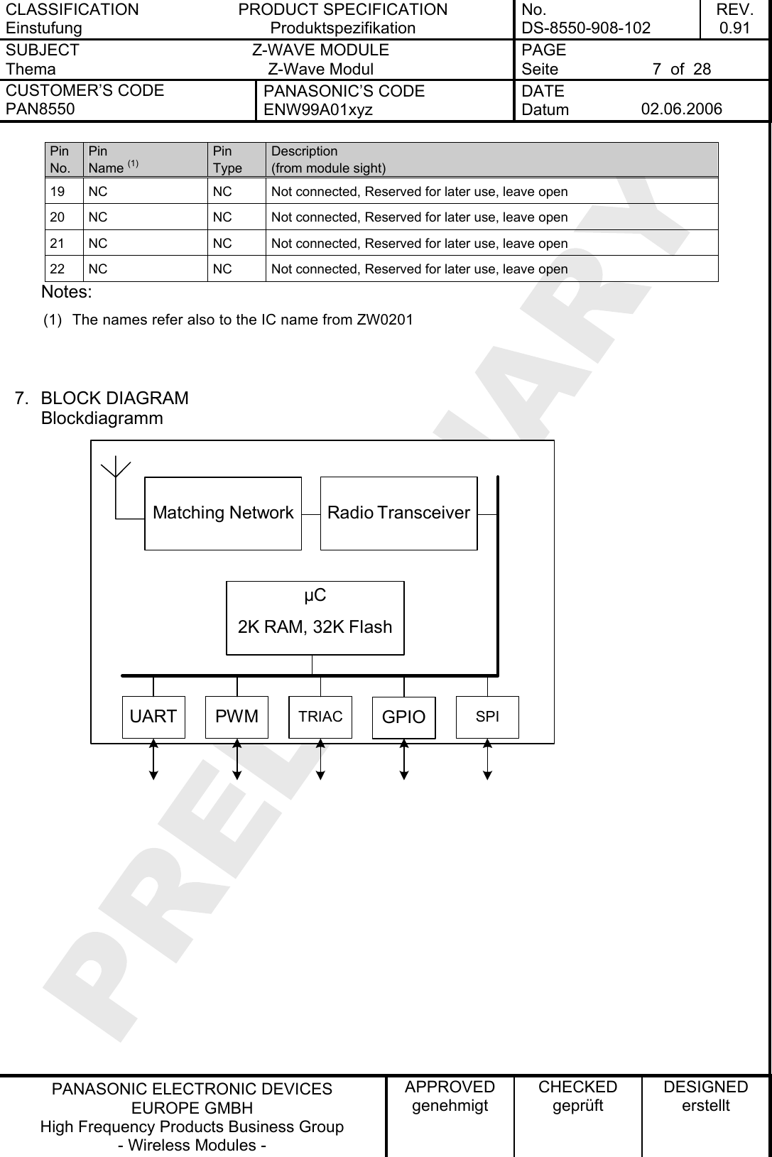
![CLASSIFICATION Einstufung PRODUCT SPECIFICATION Produktspezifikation No. DS-8550-908-102 REV. 0.91 SUBJECT Thema Z-WAVE MODULE Z-Wave Modul PAGE Seite 11 of 28 CUSTOMER’S CODE PAN8550 PANASONIC’S CODE ENW99A01xyz DATE Datum 02.06.2006 PANASONIC ELECTRONIC DEVICES EUROPE GMBH High Frequency Products Business Group - Wireless Modules - APPROVED genehmigt CHECKED geprüft DESIGNED erstellt 15. ELECTRICAL RF-CHARACTERISTICS Vcc = 3.0V, Tamb = 25°C, 50Ω antenna No Receiver Frequency [GHz] Limit / Grenzen Z-Wave Unit Nr. Empfänger Frequenz [GHz] Min Typ Max Spec Einheit 1 868.42 - -94 - 2 Sensitivity at 0.1% FER 908.42 - -94 - tbd dBm No Transmitter Frequency [GHz] Limit / Grenzen Z-Wave Unit Nr. Sender Frequenz [GHz] Min Typ Max Spec Einheit 3 868.42 - -4 - 4 RF transmit power 50 load, at UFL connector 908.42 - -4 - tbd dBm 5 RF power control range - 23 - tbd dB 6 Output power step size - 2 tbd dB 7 Frequency Accuracy 15 tbd ppm 8 2nd Harmonics content -70 -30 dBm 9 3rd Harmonics content -50 -30 dBm 10 868.42 - 0 -7.5 11 Integrated antenn again for antenna solution 908.42 - 0 -10 tbd dBi 16. MECHANICAL REQUIREMENTS Mechanische Anforderungen No. Item Punkt Limit Grenzwerte Condition Bedingung 1 Solderability Lötfähigkeit More than 75% of the soldering area shall be coated by solder Mehr als 75% der Lötfläche soll mit Lötpaste bedeckt sein. Reflow soldering with recommendable temperature profile 2 Resistance to soldering heat It shall be satisfied electrical requirements and not be mechanical damage See chapter 17.2](https://usermanual.wiki/Panasonic-Devices-Europe/PAN8550/User-Guide-666650-Page-11.png)
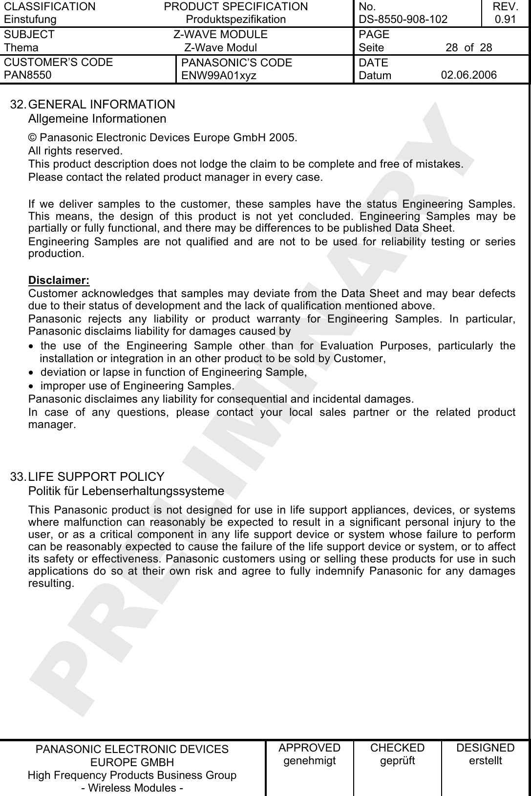
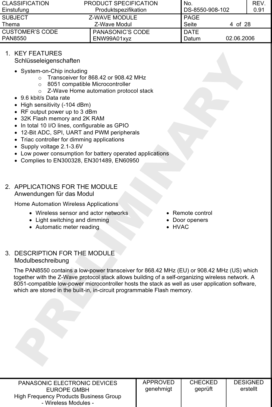
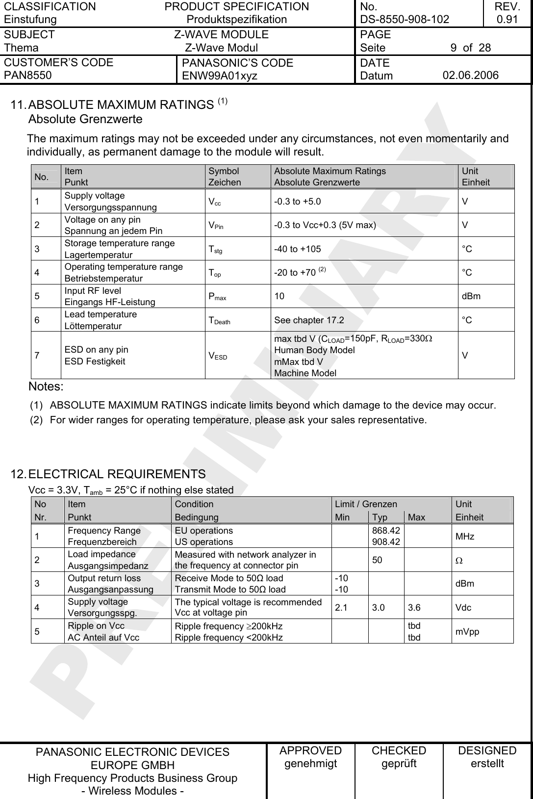
![CLASSIFICATION Einstufung PRODUCT SPECIFICATION Produktspezifikation No. DS-8550-908-102 REV. 0.91 SUBJECT Thema Z-WAVE MODULE Z-Wave Modul PAGE Seite 12 of 28 CUSTOMER’S CODE PAN8550 PANASONIC’S CODE ENW99A01xyz DATE Datum 02.06.2006 PANASONIC ELECTRONIC DEVICES EUROPE GMBH High Frequency Products Business Group - Wireless Modules - APPROVED genehmigt CHECKED geprüft DESIGNED erstellt 17. SOLDERING TEMPERATURE-TIME PROFILE (FOR REFLOW SOLDERING) Temperatur-Zeit Profil für die Reflowlötung 17.1. FOR LEAD SOLDER Recommended temp. profile for reflow soldering Temp.[°C] Time [s] 235°C max. 220 ±5°C 200°C150 ±10°C 90 ±30s 10 ±1s 30 +20/-10s 17.2. FOR LEADFREE SOLDER Our used temp. profile for reflow soldering Temp.[°C] Time [s] 230°C -250°C max. 220°C150°C – 190°C 90 ±30s 30 +20/-10s Reflow permissible cycle: 2 Opposite side reflow is prohibited due to module weight.](https://usermanual.wiki/Panasonic-Devices-Europe/PAN8550/User-Guide-666650-Page-12.png)
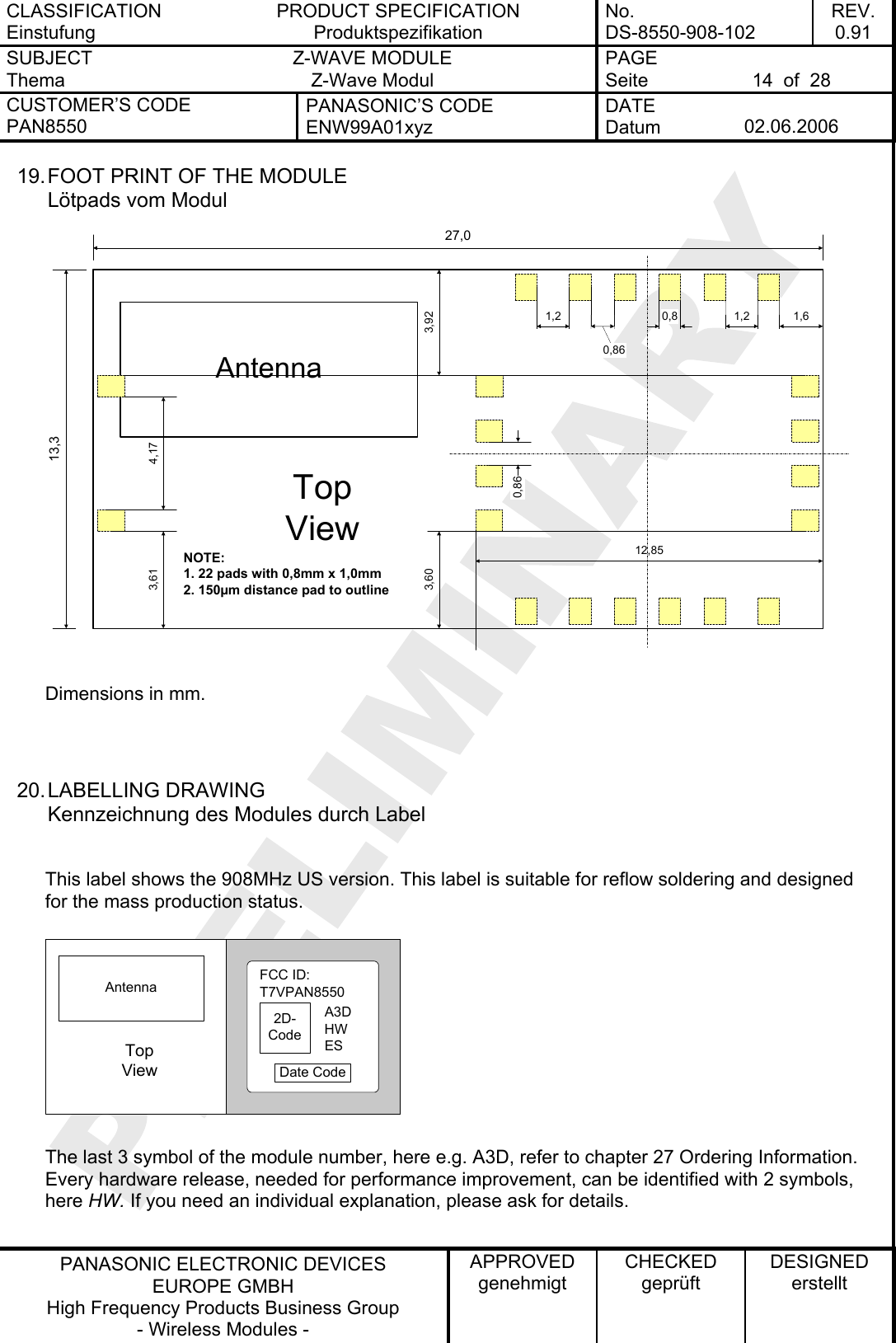
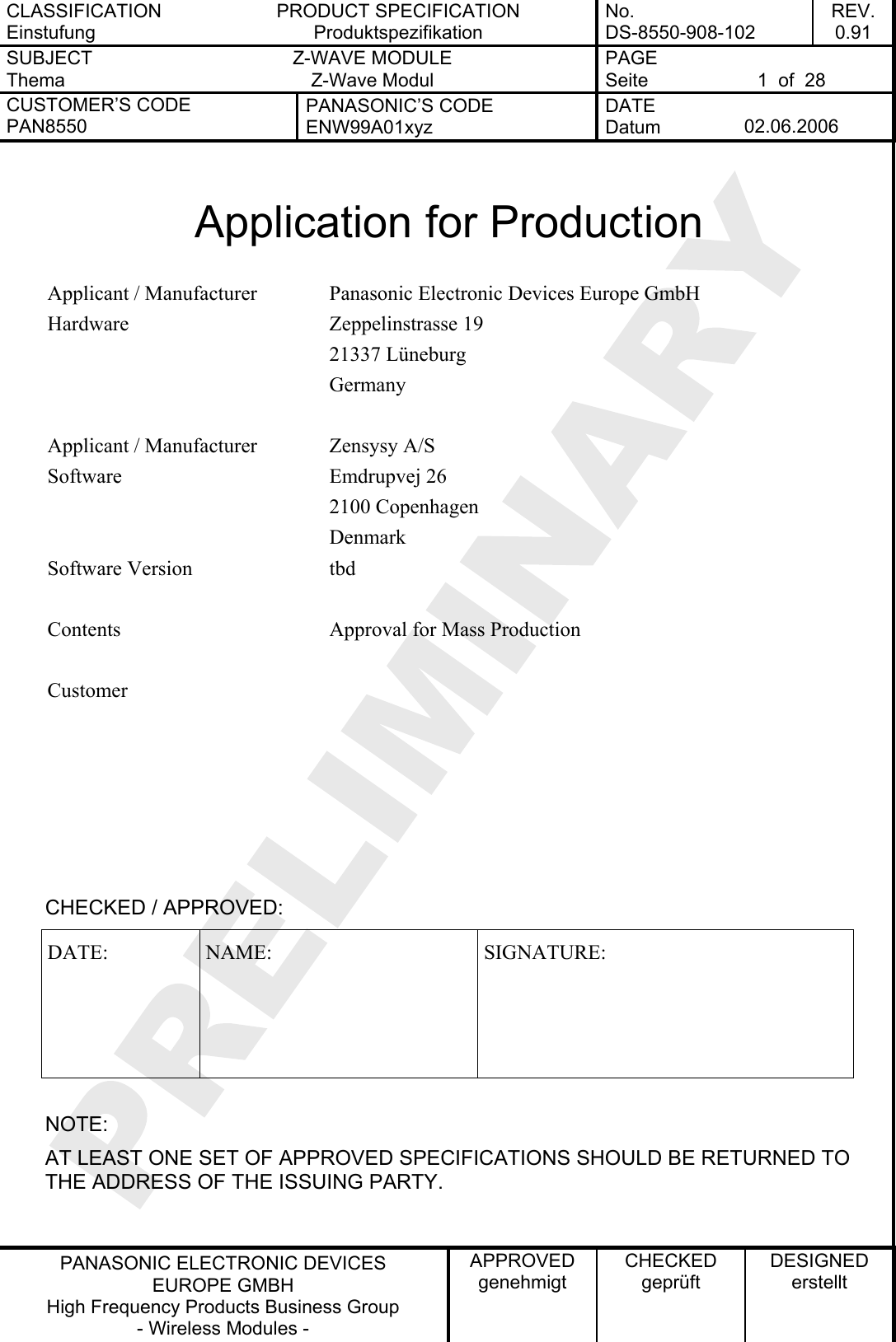
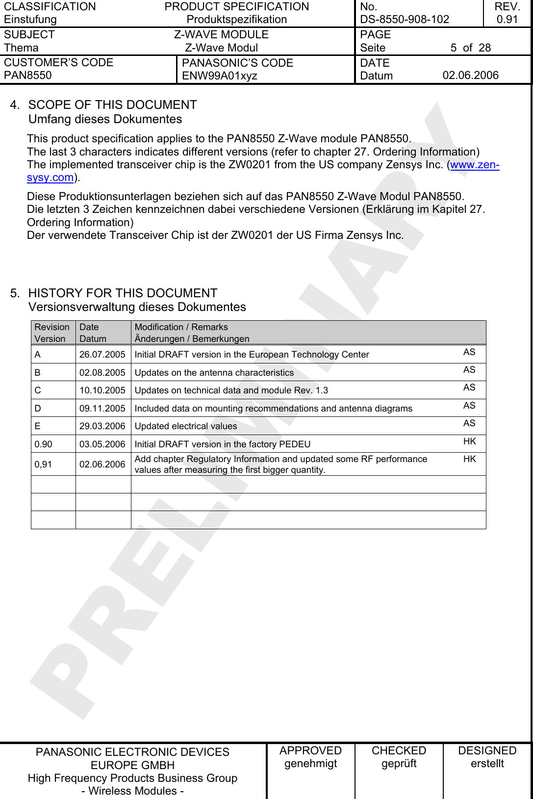
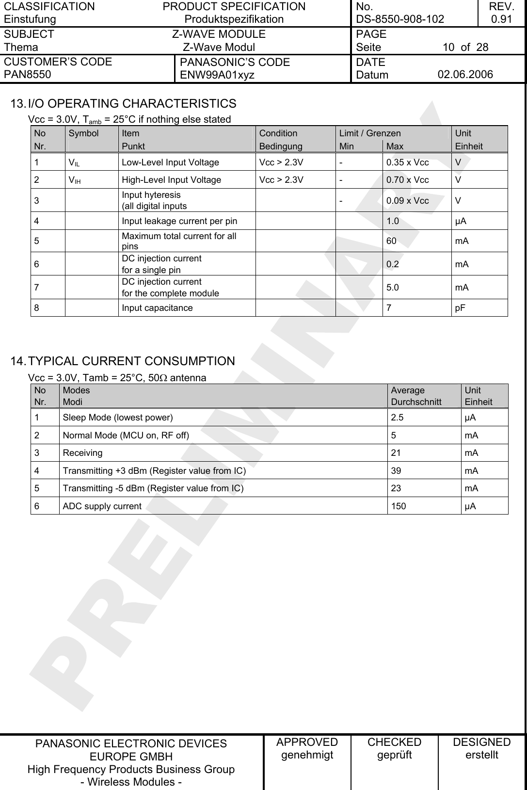
![CLASSIFICATION Einstufung PRODUCT SPECIFICATION Produktspezifikation No. DS-8550-908-102 REV. 0.91 SUBJECT Thema Z-WAVE MODULE Z-Wave Modul PAGE Seite 15 of 28 CUSTOMER’S CODE PAN8550 PANASONIC’S CODE ENW99A01xyz DATE Datum 02.06.2006 PANASONIC ELECTRONIC DEVICES EUROPE GMBH High Frequency Products Business Group - Wireless Modules - APPROVED genehmigt CHECKED geprüft DESIGNED erstellt The sign ES stands for Engineering Sample, please refer to chapter General Information. If this moule is in mass production status, the ES will be removed from the label. Information in the 2D-Barcode are the Serial Number [12 signs], the ENW-Part-Number [11 signs], the identifier for the hardware release [2 signs] and the production date code in the format Year-Month-Day [6 signs], separated by a semicolon. 21. RECOMMENDED FOOT PATTERN Empfohlenes Land Pattern 13,627,34,170,80,861,212,853,751,754,071,2NOTE:1. 18 pads with 0,8mm x 1,2mm2. 4 pads with 0,8mm x 1,0mm3. is the module outline4. 18 pads are 150µm outside the module outlineTopView3,760,86 Dimensions in mm. If you have no experience about the land pattern, this figure can guide you, but this information is given without any legal responsibility. We recommend the same dimension for the solder paste screen. The solder screen thickness depends on your production standard, we recommend 150µm. IMPORTANT: Please be careful with the area under the module to avoid short cuts. If you have any questions on this point, we are open to discuss your individual situation.](https://usermanual.wiki/Panasonic-Devices-Europe/PAN8550/User-Guide-666650-Page-15.png)
![CLASSIFICATION Einstufung PRODUCT SPECIFICATION Produktspezifikation No. DS-8550-908-102 REV. 0.91 SUBJECT Thema Z-WAVE MODULE Z-Wave Modul PAGE Seite 25 of 28 CUSTOMER’S CODE PAN8550 PANASONIC’S CODE ENW99A01xyz DATE Datum 02.06.2006 PANASONIC ELECTRONIC DEVICES EUROPE GMBH High Frequency Products Business Group - Wireless Modules - APPROVED genehmigt CHECKED geprüft DESIGNED erstellt 28. ROHS DECLARATION RoHS-Erklärung Declaration of environmental compatibility for supplied products: Hereby we declare to our best present knowledge based on declaration of our suppliers that this product do not contain by now the following substances which are banned by Directive 2002/95/EC (RoHS) or if contain a maximum concentration of 0,1% by weight in homogeneous materials for • Lead and lead compounds • Mercury and mercury compounds • Chromium (VI) • PBB (polybrominated biphenyl) category • PBDE (polybrominated biphenyl ether) category And a maximum concentration of 0,01% by weight in homogeneous materials for • Cadmium and cadmium compounds 29. DATA SHEET STATUS Datenblatt Status This data sheet contains data from the PRELIMINARY specification. Supplementary data will be published at a later date. Panasonic reserves the right to change the specification without notice, in order to improve the design and supply the best possible product. Please consult the most recently issued data sheet before initiating or completing a design. 30. RELATED DOCUMENTS Mitgeltende Dokumente [1] Data Sheet ZW0201 General Release Version 4.3 23. Feb 2005 [2] Data Sheet Antenna Johanson P/N 0920AT50A080 09/15/05 [3] Data Sheet UFL Series Hirose P/N U.FL-R-SMT 2004.2](https://usermanual.wiki/Panasonic-Devices-Europe/PAN8550/User-Guide-666650-Page-25.png)