Panasonic Devices Europe PAN8550 Z-Wave Module PAN8550 User Manual TABLE OF CONTENTS
Panasonic Industrial Devices Europe GmbH Z-Wave Module PAN8550 TABLE OF CONTENTS
Manual
CLASSIFICATION
Einstufung
PRODUCT SPECIFICATION
Produktspezifikation
No.
DS-8550-908-102
REV.
0.91
SUBJECT
Thema
Z-WAVE MODULE
Z-Wave Modul
PAGE
Seite
1 of 28
CUSTOMER’S CODE
PAN8550
PANASONIC’S CODE
ENW99A01xyz
DATE
Datum
02.06.2006
PANASONIC ELECTRONIC DEVICES
EUROPE GMBH
High Frequency Products Business Group
- Wireless Modules -
APPROVED
genehmigt
CHECKED
geprüft
DESIGNED
erstellt
Application for Production
Panasonic Electronic Devices Europe GmbH
Zeppelinstrasse 19
21337 Lüneburg
Applicant / Manufacturer
Hardware
Germany
Zensysy A/S
Emdrupvej 26
2100 Copenhagen
Applicant / Manufacturer
Software
Denmark
Software Version tbd
Contents Approval for Mass Production
Customer
CHECKED / APPROVED:
DATE: NAME: SIGNATURE:
NOTE:
AT LEAST ONE SET OF APPROVED SPECIFICATIONS SHOULD BE RETURNED TO
THE ADDRESS OF THE ISSUING PARTY.
CLASSIFICATION
Einstufung
PRODUCT SPECIFICATION
Produktspezifikation
No.
DS-8550-908-102
REV.
0.91
SUBJECT
Thema
Z-WAVE MODULE
Z-Wave Modul
PAGE
Seite
2 of 28
CUSTOMER’S CODE
PAN8550
PANASONIC’S CODE
ENW99A01xyz
DATE
Datum
02.06.2006
PANASONIC ELECTRONIC DEVICES
EUROPE GMBH
High Frequency Products Business Group
- Wireless Modules -
APPROVED
genehmigt
CHECKED
geprüft
DESIGNED
erstellt
TABLE OF CONTENTS
1. Key Features...................................................................................................................4
2. Applications for the Module.............................................................................................4
3. Description for the Module ..............................................................................................4
4. Scope of this Document..................................................................................................5
5. History for this Document................................................................................................5
6. Terminal Layout ..............................................................................................................6
6.1. Pin Assignment......................................................................................................6
7. Block Diagram.................................................................................................................7
8. PAN8550 Terminal Specifics ..........................................................................................8
8.1. RF-Interface - ANT ................................................................................................8
8.2. Reset .....................................................................................................................8
9. Key Parts List..................................................................................................................8
10. Test Conditions ...............................................................................................................8
11. Absolute Maximum Ratings (1).........................................................................................9
12. Electrical Requirements ..................................................................................................9
13. I/O Operating Characteristics........................................................................................10
14. Typical Current Consumption........................................................................................10
15. Electrical RF-Characteristics.........................................................................................11
16. Mechanical Requirements.............................................................................................11
17. Soldering Temperature-Time Profile (for reflow soldering) ...........................................12
17.1. For lead solder.....................................................................................................12
17.2. For leadfree solder...............................................................................................12
18. Module Dimension ........................................................................................................13
19. Foot Print of the Module................................................................................................14
20. Labelling Drawing..........................................................................................................14
21. Recommended Foot Pattern.........................................................................................15
22. Antenna Diagrams ........................................................................................................16
22.1. Diagrams at 868MHz ...........................................................................................16
22.2. Diagrams at 908MHz ...........................................................................................17
23. Software........................................................................................................................19
24. Reliability Tests.............................................................................................................19
25. Cautions........................................................................................................................19
25.1. Notes of design....................................................................................................19
25.2. Notes of installation .............................................................................................20
25.3. Notes of usage conditions ...................................................................................20
25.4. Notes of storage ..................................................................................................20
25.5. Other cautions .....................................................................................................20

CLASSIFICATION
Einstufung
PRODUCT SPECIFICATION
Produktspezifikation
No.
DS-8550-908-102
REV.
0.91
SUBJECT
Thema
Z-WAVE MODULE
Z-Wave Modul
PAGE
Seite
3 of 28
CUSTOMER’S CODE
PAN8550
PANASONIC’S CODE
ENW99A01xyz
DATE
Datum
02.06.2006
PANASONIC ELECTRONIC DEVICES
EUROPE GMBH
High Frequency Products Business Group
- Wireless Modules -
APPROVED
genehmigt
CHECKED
geprüft
DESIGNED
erstellt
26. Packaging .....................................................................................................................21
26.1. Embossed tape / Blistergurt.................................................................................21
26.2. Component direction............................................................................................22
26.3. Reel dimension ....................................................................................................22
26.4. Package...............................................................................................................23
27. Ordering Information .....................................................................................................24
28. RoHS Declaration .........................................................................................................25
29. Data Sheet Status.........................................................................................................25
30. Related Documents.......................................................................................................25
31. Regulatory Information..................................................................................................26
31.1. FCC Notice ..........................................................................................................26
31.2. Caution ................................................................................................................26
31.3. Labeling Requirements........................................................................................26
31.4. Antenna Warning .................................................................................................27
31.5. Approved Antenna List ........................................................................................27
31.6. RF Exposure PAN8550 .......................................................................................27
32. General Information ......................................................................................................28
33. Life Support Policy ........................................................................................................28

CLASSIFICATION
Einstufung
PRODUCT SPECIFICATION
Produktspezifikation
No.
DS-8550-908-102
REV.
0.91
SUBJECT
Thema
Z-WAVE MODULE
Z-Wave Modul
PAGE
Seite
4 of 28
CUSTOMER’S CODE
PAN8550
PANASONIC’S CODE
ENW99A01xyz
DATE
Datum
02.06.2006
PANASONIC ELECTRONIC DEVICES
EUROPE GMBH
High Frequency Products Business Group
- Wireless Modules -
APPROVED
genehmigt
CHECKED
geprüft
DESIGNED
erstellt
1. KEY FEATURES
Schlüsseleigenschaften
• System-on-Chip including
o Transceiver for 868.42 or 908.42 MHz
o 8051 compatible Microcontroller
o Z-Wave Home automation protocol stack
• 9.6 kbit/s Data rate
• High sensitivity (-104 dBm)
• RF output power up to 3 dBm
• 32K Flash memory and 2K RAM
• In total 10 I/O lines, configurable as GPIO
• 12-Bit ADC, SPI, UART and PWM peripherals
• Triac controller for dimming applications
• Supply voltage 2.1-3.6V
• Low power consumption for battery operated applications
• Complies to EN300328, EN301489, EN60950
2. APPLICATIONS FOR THE MODULE
Anwendungen für das Modul
Home Automation Wireless Applications
• Wireless sensor and actor networks • Remote control
• Light switching and dimming • Door openers
• Automatic meter reading • HVAC
3. DESCRIPTION FOR THE MODULE
Modulbeschreibung
The PAN8550 contains a low-power transceiver for 868.42 MHz (EU) or 908.42 MHz (US) which
together with the Z-Wave protocol stack allows building of a self-organizing wireless network. A
8051-compatible low-power microcontroller hosts the stack as well as user application software,
which are stored in the built-in, in-circuit programmable Flash memory.
CLASSIFICATION
Einstufung
PRODUCT SPECIFICATION
Produktspezifikation
No.
DS-8550-908-102
REV.
0.91
SUBJECT
Thema
Z-WAVE MODULE
Z-Wave Modul
PAGE
Seite
5 of 28
CUSTOMER’S CODE
PAN8550
PANASONIC’S CODE
ENW99A01xyz
DATE
Datum
02.06.2006
PANASONIC ELECTRONIC DEVICES
EUROPE GMBH
High Frequency Products Business Group
- Wireless Modules -
APPROVED
genehmigt
CHECKED
geprüft
DESIGNED
erstellt
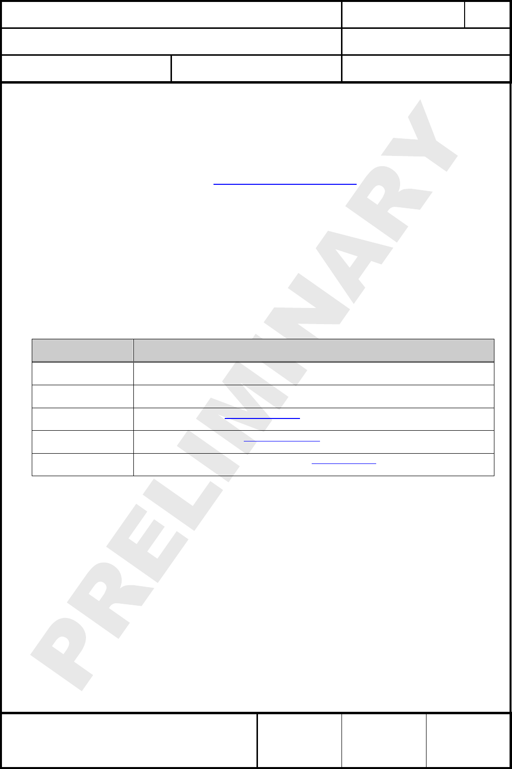
4. SCOPE OF THIS DOCUMENT
Umfang dieses Dokumentes
This product specification applies to the PAN8550 Z-Wave module PAN8550.
The last 3 characters indicates different versions (refer to chapter 27. Ordering Information)
The implemented transceiver chip is the ZW0201 from the US company Zensys Inc. (www.zen-
sysy.com).
Diese Produktionsunterlagen beziehen sich auf das PAN8550 Z-Wave Modul PAN8550.
Die letzten 3 Zeichen kennzeichnen dabei verschiedene Versionen (Erklärung im Kapitel 27.
Ordering Information)
Der verwendete Transceiver Chip ist der ZW0201 der US Firma Zensys Inc.
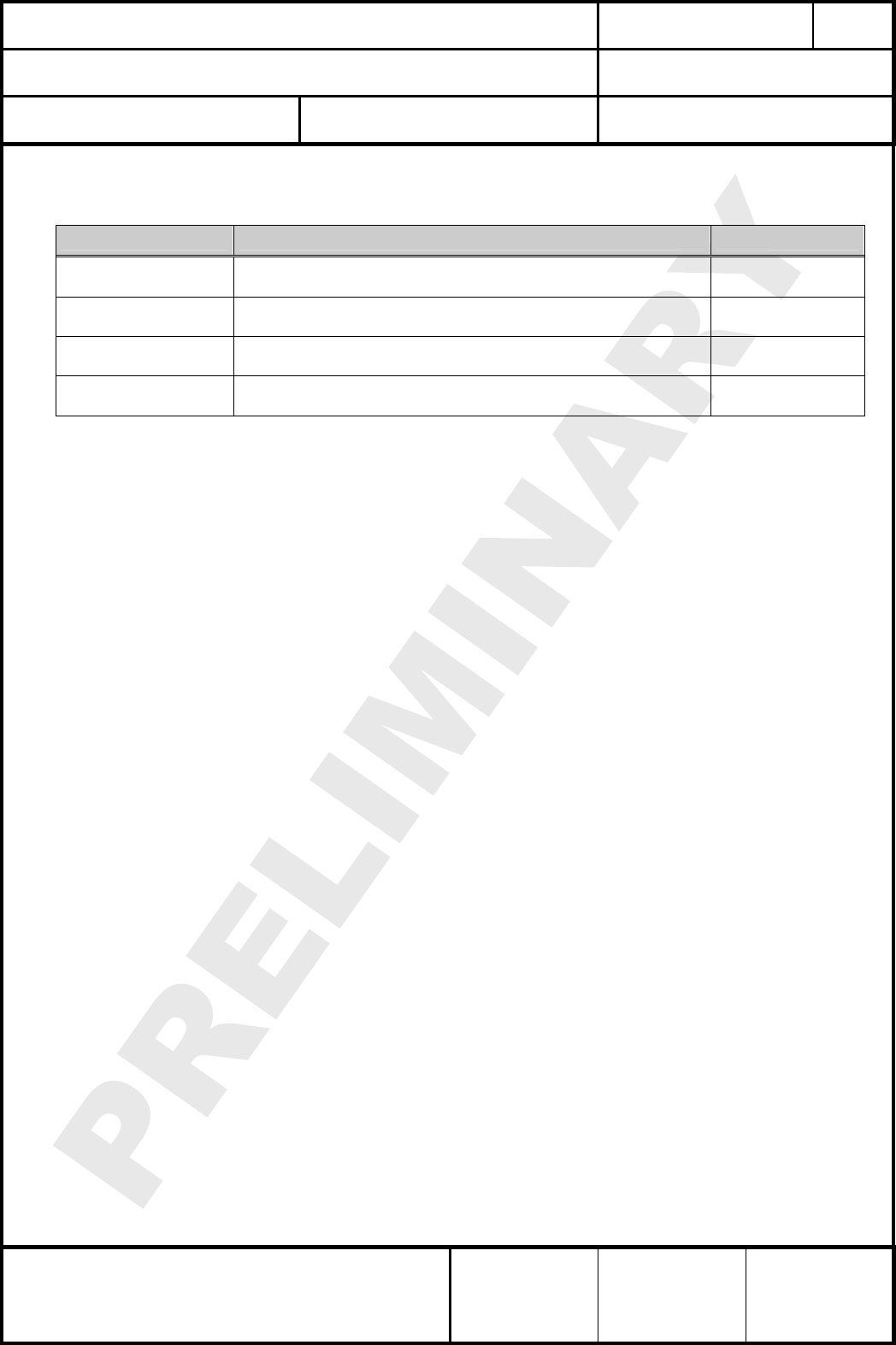
5. HISTORY FOR THIS DOCUMENT
Versionsverwaltung dieses Dokumentes
Revision
Version
Date
Datum
Modification / Remarks
Änderungen / Bemerkungen
A 26.07.2005 Initial DRAFT version in the European Technology Center AS
B 02.08.2005 Updates on the antenna characteristics AS
C 10.10.2005 Updates on technical data and module Rev. 1.3 AS
D 09.11.2005 Included data on mounting recommendations and antenna diagrams AS
E 29.03.2006 Updated electrical values AS
0.90 03.05.2006 Initial DRAFT version in the factory PEDEU HK
0,91 02.06.2006
Add chapter Regulatory Information and updated some RF performance
values after measuring the first bigger quantity.
HK
CLASSIFICATION
Einstufung
PRODUCT SPECIFICATION
Produktspezifikation
No.
DS-8550-908-102
REV.
0.91
SUBJECT
Thema
Z-WAVE MODULE
Z-Wave Modul
PAGE
Seite
6 of 28
CUSTOMER’S CODE
PAN8550
PANASONIC’S CODE
ENW99A01xyz
DATE
Datum
02.06.2006
PANASONIC ELECTRONIC DEVICES
EUROPE GMBH
High Frequency Products Business Group
- Wireless Modules -
APPROVED
genehmigt
CHECKED
geprüft
DESIGNED
erstellt
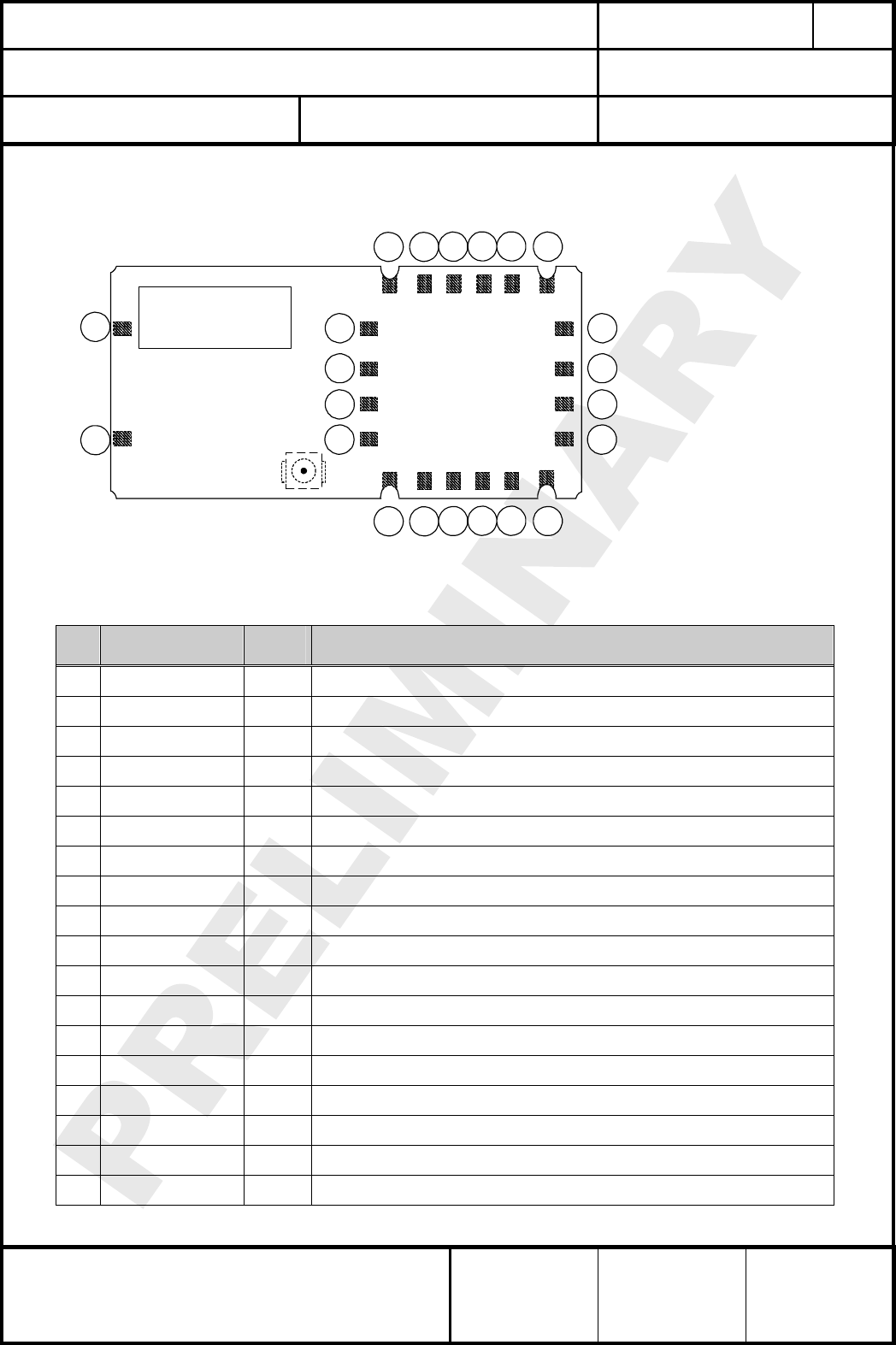
6. TERMINAL LAYOUT
Anschlußbelegung
(Top View)
Height
3,0 mm
Antenna
21 34 5 6
1516 14 13 12 11
7
8
9
10
20
19
18
17
(Optional: UFL Conn.)
21
22
6.1. PIN ASSIGNMENT
Pin
No.
Pin
Name (1)
Pin
Type
Description
(from module sight)
1 GND O ground connection (0Vdc)
2 RESET I Reset input (active low for 5 ms); Schmitt triggered
3 P1.7/INT1 I/O GPIO Port 1.7 and Interrupt Input 1
4 P1.6/INT0/PWM I/O GPIO Port 1.6, Interrupt Input 0 and PWM Port
5 P1.5/EECS I/O GPIO Port 1.5 and external EEPROM Chip-Select
6 GND O ground connection (0Vdc)
7 P1.4/SCK I/O GPIO Port 1.4 and SPI Clock Signal
8 P1.3/MOSI I/O GPIO Port 1.3 and SPI Master Out Slave In
9 P1.2/MISO O GPIO Port 1.2 and SPI Master In Slave Out
10 P1.1/RXD/ADC I/O GPIO Port 1.1, UART RxD Input and multiplexed ADC port
11 GND O ground connection (0Vdc)
12 VCC I DC Power supply, typical 3.3V DC
13 P1.0/TXD/ADC I/O GPIO Port 1.1, UART TxD Output and multiplexed ADC port
14 P0.1/ADC/TRIAC I/O GPIO Port 0.1, multiplexed ADC port and Triac control output
15 P0.0/ADC/ZEROX I/O GPIO Port 0.0, multiplexed ADC port and Zero crossing input
16 GND O ground connection (0Vdc)
17 NC NC Not connected, Reserved for later use, leave open
18 NC NC Not connected, Reserved for later use, leave open
CLASSIFICATION
Einstufung
PRODUCT SPECIFICATION
Produktspezifikation
No.
DS-8550-908-102
REV.
0.91
SUBJECT
Thema
Z-WAVE MODULE
Z-Wave Modul
PAGE
Seite
7 of 28
CUSTOMER’S CODE
PAN8550
PANASONIC’S CODE
ENW99A01xyz
DATE
Datum
02.06.2006
PANASONIC ELECTRONIC DEVICES
EUROPE GMBH
High Frequency Products Business Group
- Wireless Modules -
APPROVED
genehmigt
CHECKED
geprüft
DESIGNED
erstellt
Pin
No.
Pin
Name (1)
Pin
Type
Description
(from module sight)
19 NC NC Not connected, Reserved for later use, leave open
20 NC NC Not connected, Reserved for later use, leave open
21 NC NC Not connected, Reserved for later use, leave open
22 NC NC Not connected, Reserved for later use, leave open
Notes:
(1) The names refer also to the IC name from ZW0201
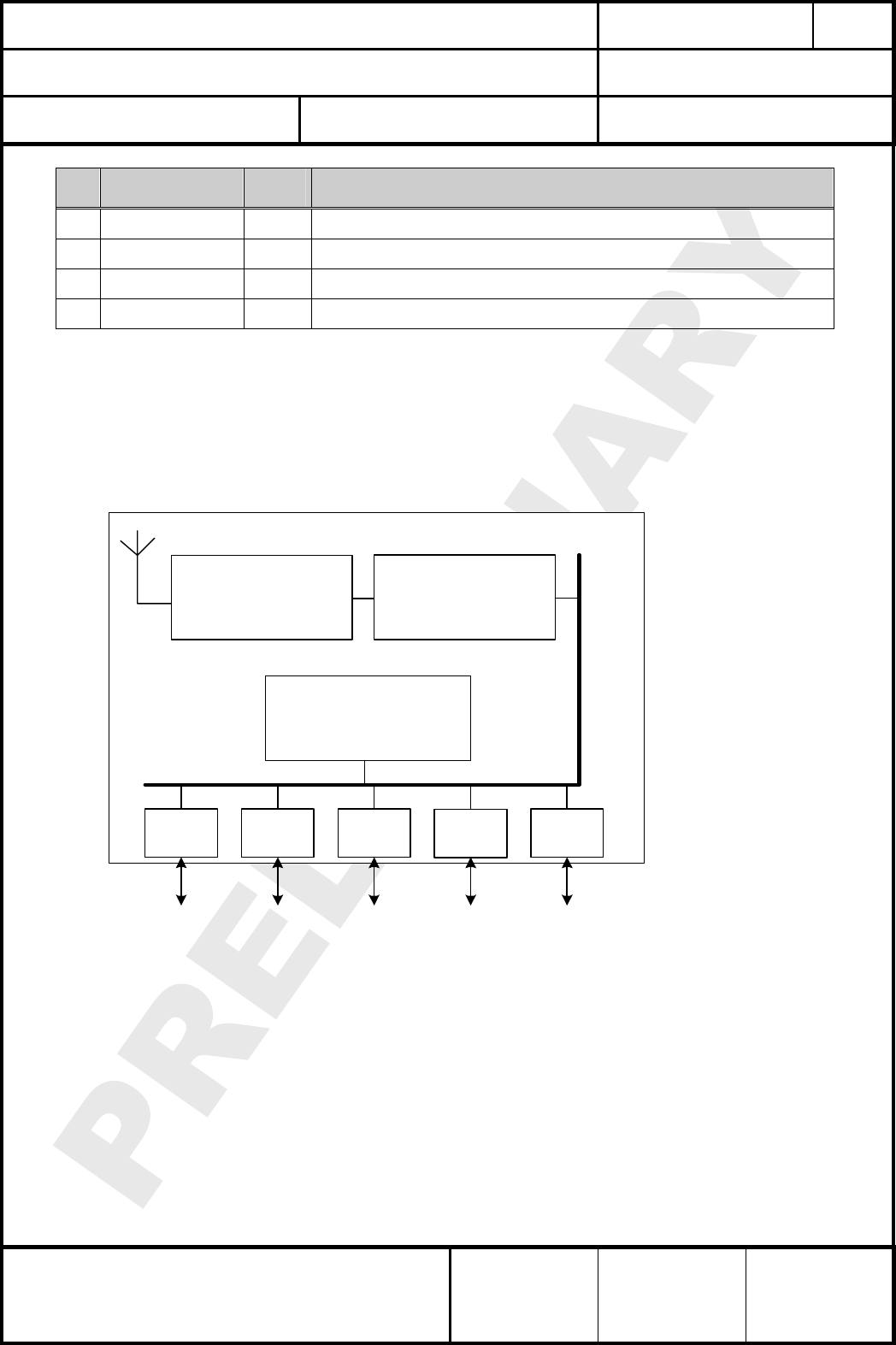
7. BLOCK DIAGRAM
Blockdiagramm
µC
2K RAM, 32K Flash
Radio Transceiver
Matching Network
UART TRIAC
PWM SPI
GPIO
CLASSIFICATION
Einstufung
PRODUCT SPECIFICATION
Produktspezifikation
No.
DS-8550-908-102
REV.
0.91
SUBJECT
Thema
Z-WAVE MODULE
Z-Wave Modul
PAGE
Seite
8 of 28
CUSTOMER’S CODE
PAN8550
PANASONIC’S CODE
ENW99A01xyz
DATE
Datum
02.06.2006
PANASONIC ELECTRONIC DEVICES
EUROPE GMBH
High Frequency Products Business Group
- Wireless Modules -
APPROVED
genehmigt
CHECKED
geprüft
DESIGNED
erstellt
8. PAN8550 TERMINAL SPECIFICS
PAN8550 Interfacebeschreibungen
8.1. RF-INTERFACE - ANT
The PAN8550 presents a 50 impedance on the plug connector. If you need additional
antenna support please e-mail to wireless@ecom.panasonic.de or use the PAN8550 with
integrated ceramic antenna. The details please refer to chapter 27.
8.2. RESET
The RESET pin is an active low input that can be used to perform a full reset of the device
from an external signal. This pin does not contain an internal pull-up, so it should be pulled-up
externally if not used.
9. KEY PARTS LIST
Liste der Schlüsselkomponenten
Part Name
Teilenummer
Material
Material
P.W.Board
Leiterplatte
Glass cloth epoxide resin with gold plating
FR4 mit Goldauflage
Casing
Deckel
Material: CuNi18ZN20, thickness 0.2mm
Material: Weißblech 0,2mm Dicke
IC part name
IC Name
ZW0201 (Zensysy Inc www.zen-sysy.com)
All information are based on [1] chapter 30
Antenna name
Antennenname
0920AT50A080 (Johanson www.johanson.com)
All information are based on [2] chapter 30
Connector name
Steckername
U.FL-R-SMT(10) No. 331-0471-0-10 (Hirose www.hirose.com)
All information are based on [3] chapter 30
10. TEST CONDITIONS
Meßbedingungen
Measurements shall be made under room temperature and humidity unless otherwise specified.
Messungen unter normalen Bedingungen, Abweichungen sind gesondert notiert.
Temperature 25 ± 10°C Humidity 40 to 85%RH
Temperatur 25 ± 10°C Luftfeuchtigkeit 40 to 85%RH
CLASSIFICATION
Einstufung
PRODUCT SPECIFICATION
Produktspezifikation
No.
DS-8550-908-102
REV.
0.91
SUBJECT
Thema
Z-WAVE MODULE
Z-Wave Modul
PAGE
Seite
9 of 28
CUSTOMER’S CODE
PAN8550
PANASONIC’S CODE
ENW99A01xyz
DATE
Datum
02.06.2006
PANASONIC ELECTRONIC DEVICES
EUROPE GMBH
High Frequency Products Business Group
- Wireless Modules -
APPROVED
genehmigt
CHECKED
geprüft
DESIGNED
erstellt
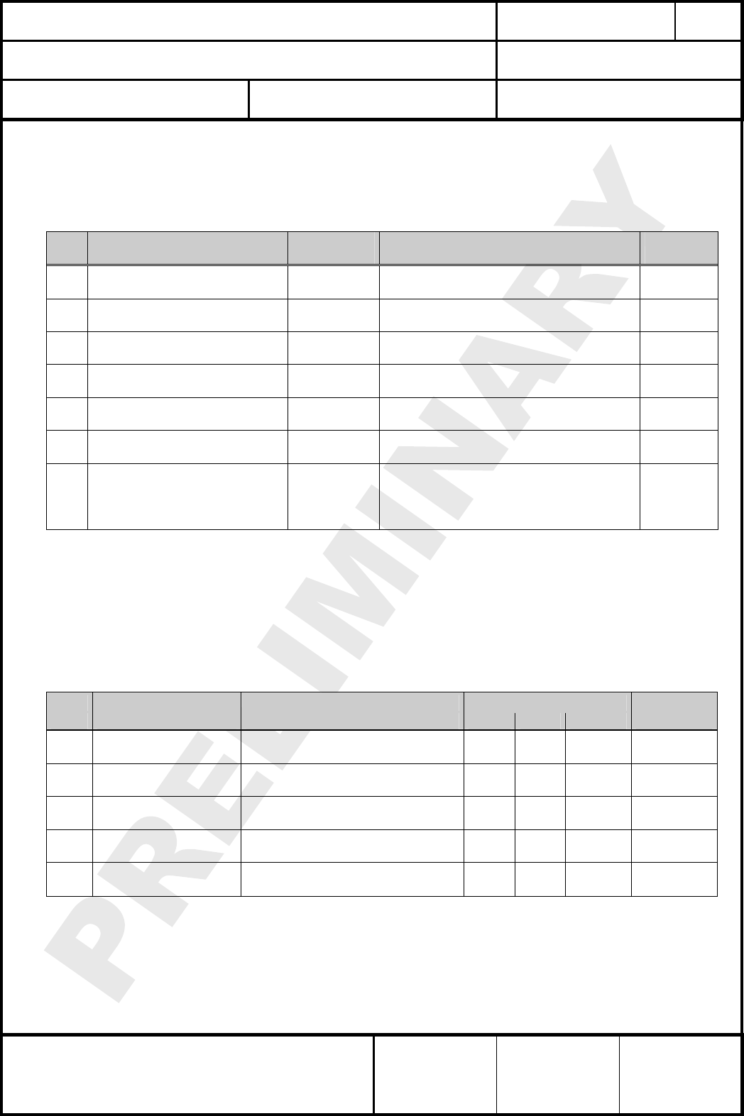
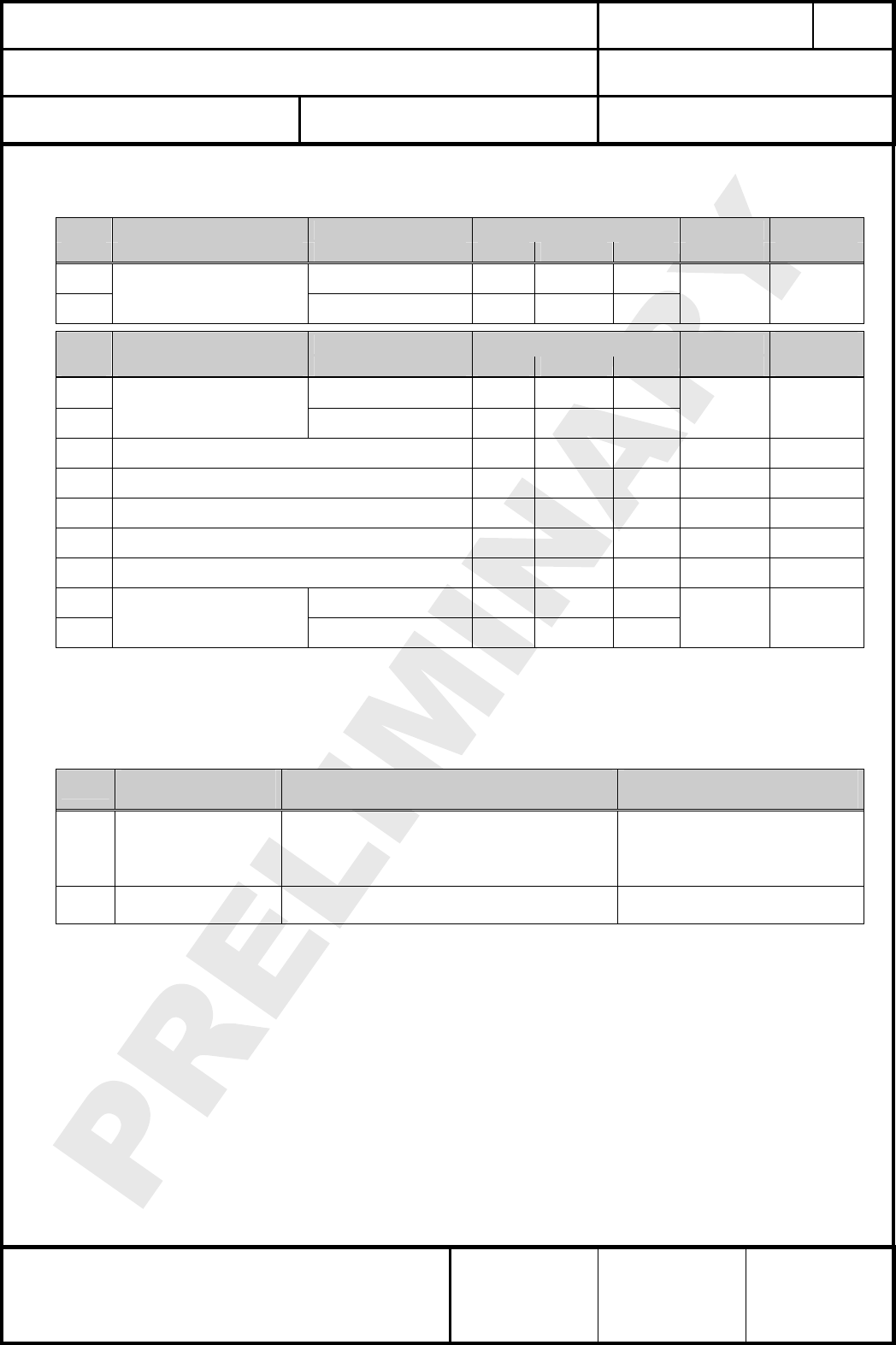
11. ABSOLUTE MAXIMUM RATINGS (1)
Absolute Grenzwerte
The maximum ratings may not be exceeded under any circumstances, not even momentarily and
individually, as permanent damage to the module will result.
No. Item
Punkt
Symbol
Zeichen
Absolute Maximum Ratings
Absolute Grenzwerte
Unit
Einheit
1 Supply voltage
Versorgungsspannung Vcc -0.3 to +5.0 V
2 Voltage on any pin
Spannung an jedem Pin VPin -0.3 to Vcc+0.3 (5V max) V
3 Storage temperature range
Lagertemperatur Tstg -40 to +105 °C
4 Operating temperature range
Betriebstemperatur Top -20 to +70 (2) °C
5 Input RF level
Eingangs HF-Leistung Pmax 10 dBm
6 Lead temperature
Löttemperatur TDeath See chapter 17.2 °C
7 ESD on any pin
ESD Festigkeit VESD
max tbd V (CLOAD=150pF, RLOAD=330Ω
Human Body Model
mMax tbd V
Machine Model
V
Notes:
(1) ABSOLUTE MAXIMUM RATINGS indicate limits beyond which damage to the device may occur.
(2) For wider ranges for operating temperature, please ask your sales representative.
12. ELECTRICAL REQUIREMENTS
Vcc = 3.3V, Tamb = 25°C if nothing else stated
No Item Condition Limit / Grenzen Unit
Nr. Punkt Bedingung Min Typ Max Einheit
1 Frequency Range
Frequenzbereich
EU operations
US operations 868.42
908.42 MHz
2 Load impedance
Ausgangsimpedanz
Measured with network analyzer in
the frequency at connector pin 50 Ω
3 Output return loss
Ausgangsanpassung
Receive Mode to 50 load
Transmit Mode to 50 load
-10
-10 dBm
4 Supply voltage
Versorgungsspg.
The typical voltage is recommended
Vcc at voltage pin 2.1 3.0 3.6 Vdc
5 Ripple on Vcc
AC Anteil auf Vcc
Ripple frequency ≥200kHz
Ripple frequency <200kHz tbd
tbd mVpp
CLASSIFICATION
Einstufung
PRODUCT SPECIFICATION
Produktspezifikation
No.
DS-8550-908-102
REV.
0.91
SUBJECT
Thema
Z-WAVE MODULE
Z-Wave Modul
PAGE
Seite
10 of 28
CUSTOMER’S CODE
PAN8550
PANASONIC’S CODE
ENW99A01xyz
DATE
Datum
02.06.2006
PANASONIC ELECTRONIC DEVICES
EUROPE GMBH
High Frequency Products Business Group
- Wireless Modules -
APPROVED
genehmigt
CHECKED
geprüft
DESIGNED
erstellt
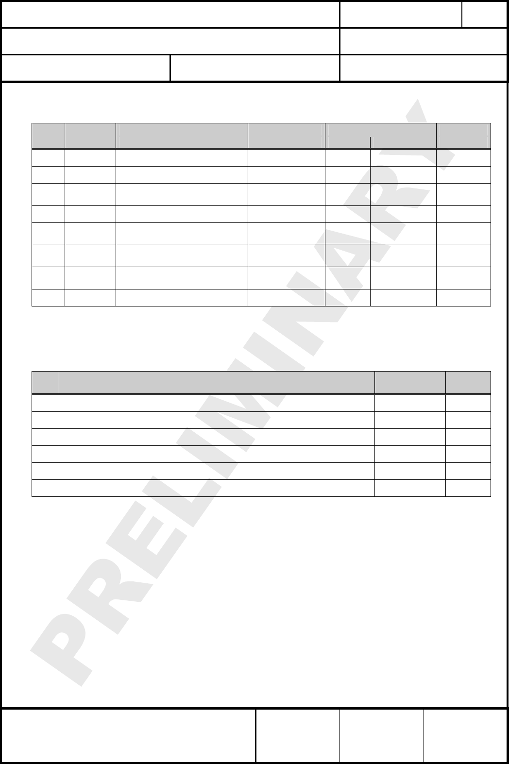
13. I/O OPERATING CHARACTERISTICS
Vcc = 3.0V, Tamb = 25°C if nothing else stated
No Symbol Item Condition Limit / Grenzen Unit
Nr. Punkt Bedingung Min Max Einheit
1 VIL Low-Level Input Voltage Vcc > 2.3V - 0.35 x Vcc V
2 VIH High-Level Input Voltage Vcc > 2.3V - 0.70 x Vcc V
3 Input hyteresis
(all digital inputs - 0.09 x Vcc V
4 Input leakage current per pin 1.0 µA
5 Maximum total current for all
pins 60 mA
6 DC injection current
for a single pin 0.2 mA
7 DC injection current
for the complete module 5.0 mA
8 Input capacitance 7 pF
14. TYPICAL CURRENT CONSUMPTION
Vcc = 3.0V, Tamb = 25°C, 50Ω antenna
No
Nr.
Modes
Modi
Average
Durchschnitt
Unit
Einheit
1 Sleep Mode (lowest power) 2.5 µA
2 Normal Mode (MCU on, RF off) 5 mA
3 Receiving 21 mA
4 Transmitting +3 dBm (Register value from IC) 39 mA
5 Transmitting -5 dBm (Register value from IC) 23 mA
6 ADC supply current 150 µA
CLASSIFICATION
Einstufung
PRODUCT SPECIFICATION
Produktspezifikation
No.
DS-8550-908-102
REV.
0.91
SUBJECT
Thema
Z-WAVE MODULE
Z-Wave Modul
PAGE
Seite
11 of 28
CUSTOMER’S CODE
PAN8550
PANASONIC’S CODE
ENW99A01xyz
DATE
Datum
02.06.2006
PANASONIC ELECTRONIC DEVICES
EUROPE GMBH
High Frequency Products Business Group
- Wireless Modules -
APPROVED
genehmigt
CHECKED
geprüft
DESIGNED
erstellt
15. ELECTRICAL RF-CHARACTERISTICS
Vcc = 3.0V, Tamb = 25°C, 50Ω antenna
No Receiver Frequency [GHz] Limit / Grenzen Z-Wave Unit
Nr. Empfänger Frequenz [GHz] Min Typ Max Spec Einheit
1 868.42 - -94 -
2 Sensitivity at 0.1% FER 908.42 - -94 -
tbd dBm
No Transmitter Frequency [GHz] Limit / Grenzen Z-Wave Unit
Nr. Sender Frequenz [GHz] Min Typ Max Spec Einheit
3 868.42 - -4 -
4
RF transmit power
50 load, at UFL
connector 908.42 - -4 -
tbd dBm
5 RF power control range - 23 - tbd dB
6 Output power step size - 2 tbd dB
7 Frequency Accuracy 15 tbd ppm
8 2nd Harmonics content -70 -30 dBm
9 3rd Harmonics content -50 -30 dBm
10 868.42 - 0 -7.5
11
Integrated antenn again
for antenna solution 908.42 - 0 -10
tbd dBi
16. MECHANICAL REQUIREMENTS
Mechanische Anforderungen
No. Item
Punkt
Limit
Grenzwerte
Condition
Bedingung
1 Solderability
Lötfähigkeit
More than 75% of the soldering area shall be
coated by solder
Mehr als 75% der Lötfläche soll mit Lötpaste
bedeckt sein.
Reflow soldering with
recommendable temperature
profile
2 Resistance to
soldering heat
It shall be satisfied electrical requirements and
not be mechanical damage See chapter 17.2
CLASSIFICATION
Einstufung
PRODUCT SPECIFICATION
Produktspezifikation
No.
DS-8550-908-102
REV.
0.91
SUBJECT
Thema
Z-WAVE MODULE
Z-Wave Modul
PAGE
Seite
12 of 28
CUSTOMER’S CODE
PAN8550
PANASONIC’S CODE
ENW99A01xyz
DATE
Datum
02.06.2006
PANASONIC ELECTRONIC DEVICES
EUROPE GMBH
High Frequency Products Business Group
- Wireless Modules -
APPROVED
genehmigt
CHECKED
geprüft
DESIGNED
erstellt
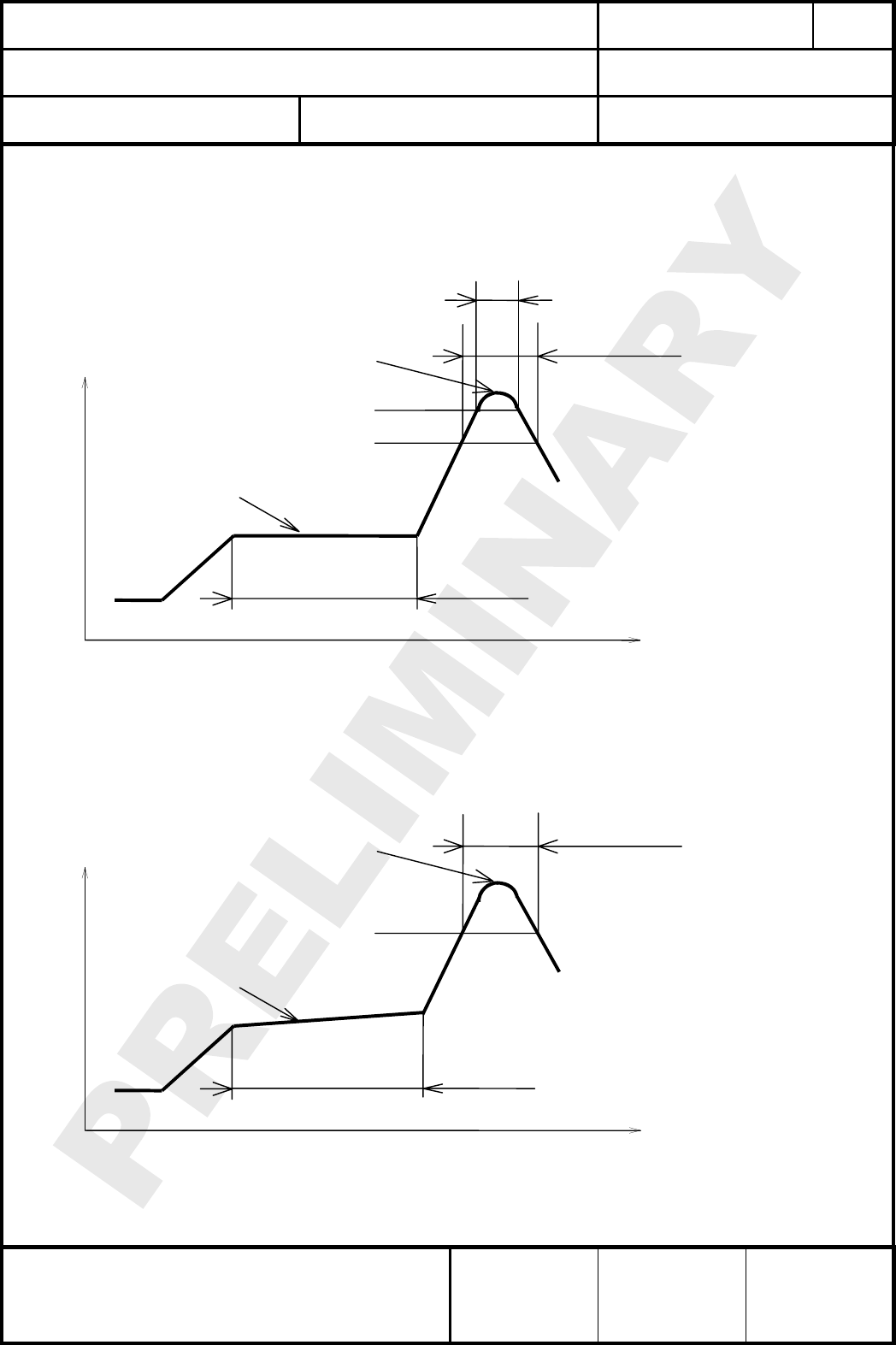
17. SOLDERING TEMPERATURE-TIME PROFILE (FOR REFLOW SOLDERING)
Temperatur-Zeit Profil für die Reflowlötung
17.1. FOR LEAD SOLDER
Recommended temp. profile
for reflow soldering
Tem
p
.
[
°C
]
Time [s]
235°C max.
220 ±5°C
200°C
150 ±10°C
90 ±30s
10
±
1s
30 +20/-10s
17.2. FOR LEADFREE SOLDER
Our used temp. profile
for reflow soldering
Temp.[°C]
Time [s]
230°C -250°C max.
220°C
150°C – 190°C
90 ±30s
30 +20/-10s
Reflow permissible cycle: 2
Opposite side reflow is prohibited due to module weight.
CLASSIFICATION
Einstufung
PRODUCT SPECIFICATION
Produktspezifikation
No.
DS-8550-908-102
REV.
0.91
SUBJECT
Thema
Z-WAVE MODULE
Z-Wave Modul
PAGE
Seite
13 of 28
CUSTOMER’S CODE
PAN8550
PANASONIC’S CODE
ENW99A01xyz
DATE
Datum
02.06.2006
PANASONIC ELECTRONIC DEVICES
EUROPE GMBH
High Frequency Products Business Group
- Wireless Modules -
APPROVED
genehmigt
CHECKED
geprüft
DESIGNED
erstellt
18. MODULE DIMENSION
Modulabmessungen
No. Item
Punkt
Dimension
Abmessung
Tolerance
Toleranz
Remark
Bemerkung
1 Width 13.30 ± 0.2
2 Lenght 27,00 ± 0.2
3 Hight 3.10 ± 0.05
CLASSIFICATION
Einstufung
PRODUCT SPECIFICATION
Produktspezifikation
No.
DS-8550-908-102
REV.
0.91
SUBJECT
Thema
Z-WAVE MODULE
Z-Wave Modul
PAGE
Seite
14 of 28
CUSTOMER’S CODE
PAN8550
PANASONIC’S CODE
ENW99A01xyz
DATE
Datum
02.06.2006
PANASONIC ELECTRONIC DEVICES
EUROPE GMBH
High Frequency Products Business Group
- Wireless Modules -
APPROVED
genehmigt
CHECKED
geprüft
DESIGNED
erstellt
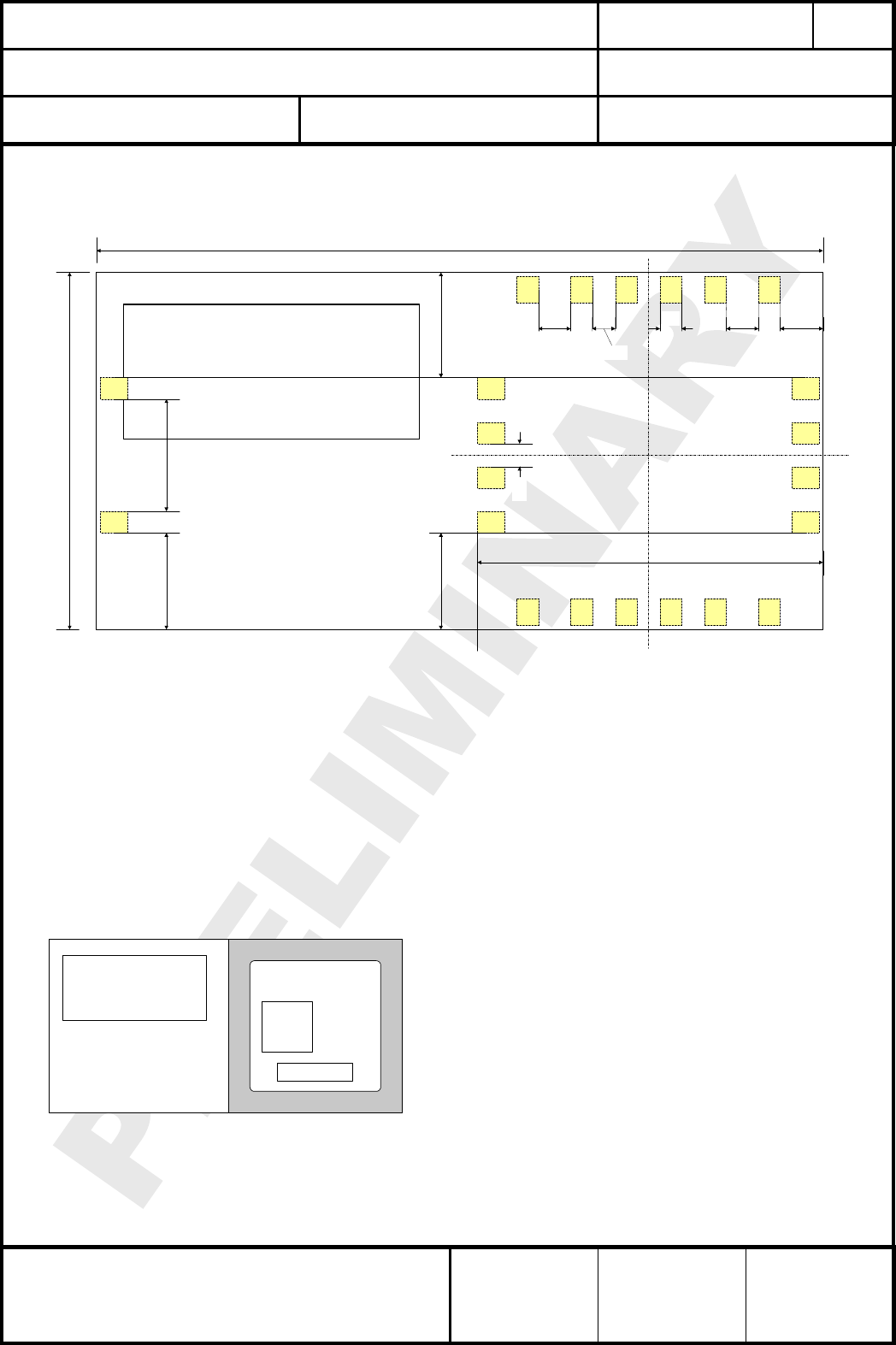
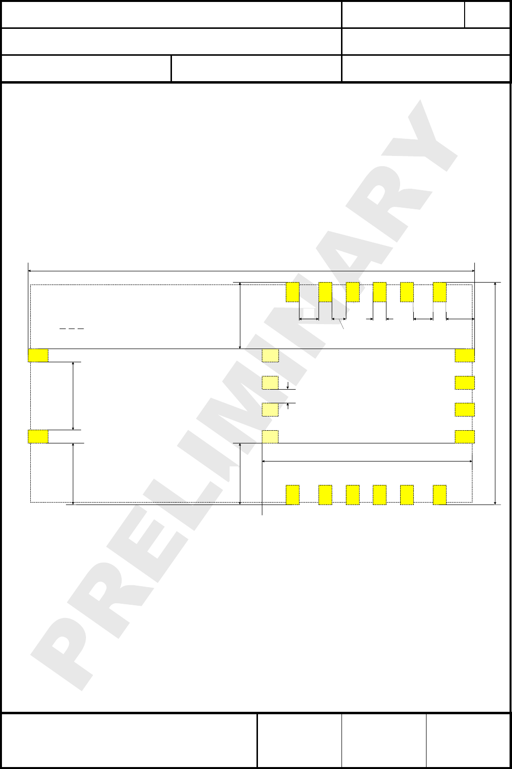
19. FOOT PRINT OF THE MODULE
Lötpads vom Modul
Antenna
13,3
27,0
4,17
0,8
0,86
1,2
12,85
3,60
1,6
3,92
1,2
NOTE:
1. 22 pads with 0,8mm x 1,0mm
2. 150µm distance pad to outline
Top
View
3,61
0,86
Dimensions in mm.
20. LABELLING DRAWING
Kennzeichnung des Modules durch Label
This label shows the 908MHz US version. This label is suitable for reflow soldering and designed
for the mass production status.
2D-
Code
FCC ID:
T7VPAN8550
Date Code
A3D
Antenna
HW
Top
View
ES
The last 3 symbol of the module number, here e.g. A3D, refer to chapter 27 Ordering Information.
Every hardware release, needed for performance improvement, can be identified with 2 symbols,
here HW. If you need an individual explanation, please ask for details.
CLASSIFICATION
Einstufung
PRODUCT SPECIFICATION
Produktspezifikation
No.
DS-8550-908-102
REV.
0.91
SUBJECT
Thema
Z-WAVE MODULE
Z-Wave Modul
PAGE
Seite
15 of 28
CUSTOMER’S CODE
PAN8550
PANASONIC’S CODE
ENW99A01xyz
DATE
Datum
02.06.2006
PANASONIC ELECTRONIC DEVICES
EUROPE GMBH
High Frequency Products Business Group
- Wireless Modules -
APPROVED
genehmigt
CHECKED
geprüft
DESIGNED
erstellt
The sign ES stands for Engineering Sample, please refer to chapter General Information. If this
moule is in mass production status, the ES will be removed from the label.
Information in the 2D-Barcode are the Serial Number [12 signs], the ENW-Part-Number [11 signs],
the identifier for the hardware release [2 signs] and the production date code in the format Year-
Month-Day [6 signs], separated by a semicolon.
21. RECOMMENDED FOOT PATTERN
Empfohlenes Land Pattern
13,6
27,3
4,17
0,8
0,86
1,2
12,85
3,75
1,75
4,07
1,2
NOTE:
1. 18 pads with 0,8mm x 1,2mm
2. 4 pads with 0,8mm x 1,0mm
3. is the module outline
4. 18 pads are 150µm outside the module outline
Top
View
3,76
0,86
Dimensions in mm.
If you have no experience about the land pattern, this figure can guide you, but this information is
given without any legal responsibility.
We recommend the same dimension for the solder paste screen.
The solder screen thickness depends on your production standard, we recommend 150µm.
IMPORTANT:
Please be careful with the area under the module to avoid short cuts.
If you have any questions on this point, we are open to discuss your individual situation.
CLASSIFICATION
Einstufung
PRODUCT SPECIFICATION
Produktspezifikation
No.
DS-8550-908-102
REV.
0.91
SUBJECT
Thema
Z-WAVE MODULE
Z-Wave Modul
PAGE
Seite
16 of 28
CUSTOMER’S CODE
PAN8550
PANASONIC’S CODE
ENW99A01xyz
DATE
Datum
02.06.2006
PANASONIC ELECTRONIC DEVICES
EUROPE GMBH
High Frequency Products Business Group
- Wireless Modules -
APPROVED
genehmigt
CHECKED
geprüft
DESIGNED
erstellt
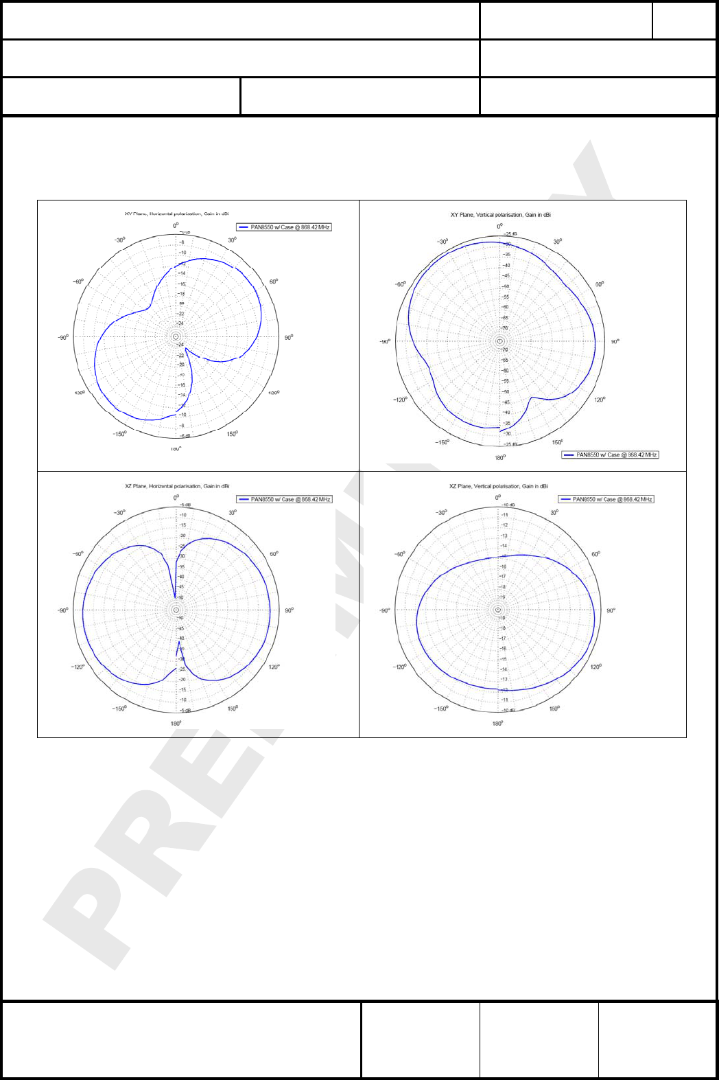
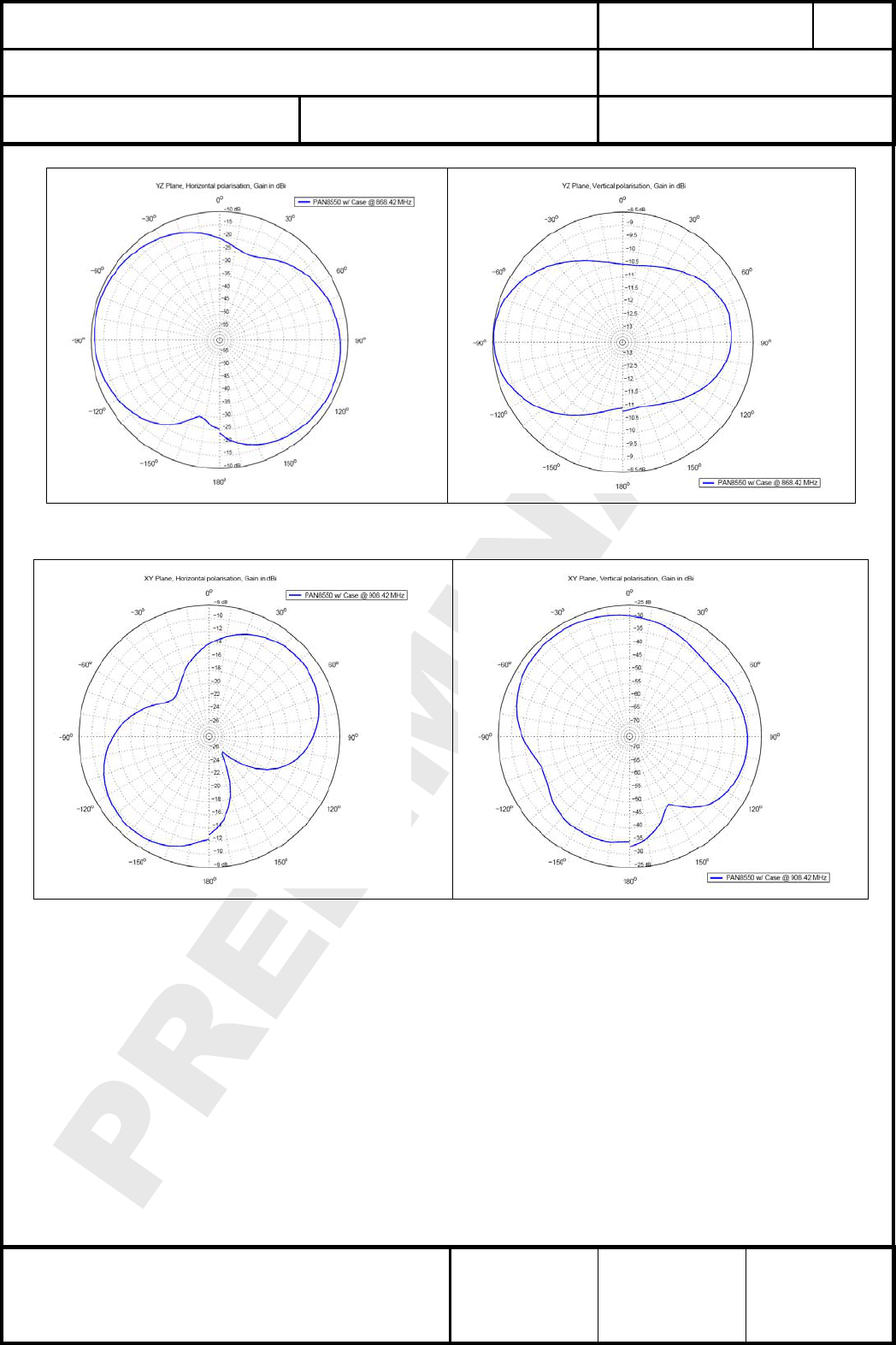
22. ANTENNA DIAGRAMS
Antennenrichtdiagramme
22.1. DIAGRAMS AT 868MHZ
CLASSIFICATION
Einstufung
PRODUCT SPECIFICATION
Produktspezifikation
No.
DS-8550-908-102
REV.
0.91
SUBJECT
Thema
Z-WAVE MODULE
Z-Wave Modul
PAGE
Seite
17 of 28
CUSTOMER’S CODE
PAN8550
PANASONIC’S CODE
ENW99A01xyz
DATE
Datum
02.06.2006
PANASONIC ELECTRONIC DEVICES
EUROPE GMBH
High Frequency Products Business Group
- Wireless Modules -
APPROVED
genehmigt
CHECKED
geprüft
DESIGNED
erstellt
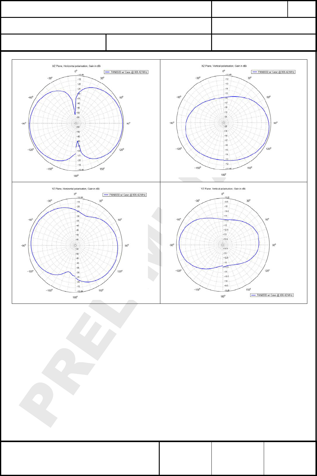
22.2. DIAGRAMS AT 908MHZ
CLASSIFICATION
Einstufung
PRODUCT SPECIFICATION
Produktspezifikation
No.
DS-8550-908-102
REV.
0.91
SUBJECT
Thema
Z-WAVE MODULE
Z-Wave Modul
PAGE
Seite
18 of 28
CUSTOMER’S CODE
PAN8550
PANASONIC’S CODE
ENW99A01xyz
DATE
Datum
02.06.2006
PANASONIC ELECTRONIC DEVICES
EUROPE GMBH
High Frequency Products Business Group
- Wireless Modules -
APPROVED
genehmigt
CHECKED
geprüft
DESIGNED
erstellt
CLASSIFICATION
Einstufung
PRODUCT SPECIFICATION
Produktspezifikation
No.
DS-8550-908-102
REV.
0.91
SUBJECT
Thema
Z-WAVE MODULE
Z-Wave Modul
PAGE
Seite
19 of 28
CUSTOMER’S CODE
PAN8550
PANASONIC’S CODE
ENW99A01xyz
DATE
Datum
02.06.2006
PANASONIC ELECTRONIC DEVICES
EUROPE GMBH
High Frequency Products Business Group
- Wireless Modules -
APPROVED
genehmigt
CHECKED
geprüft
DESIGNED
erstellt
23. SOFTWARE
Software
Defined in a later version, but please be informed, that the basic software come from company
Zensysy. To get this basic software you need a membership in the Z-Wave alliance.
Details could be found under www.z-wavealliance.org.
24. RELIABILITY TESTS
Zuverlässigkeitstests
The measurement should be done after exposed to room temperature and humidity for 1hour.
Die Messungen sollten erst nach einer Stunde Lagerung unter normalen Bedingungen erfolgen.
No. Item
Punkt
Limit
Grenzwerte
Condition
Bedingung
1 Vibration test Electrical parameter should be
in specification
a) Freq.:10~50Hz,Amplitude:1.5mm
a) 20min. / cycle,1hrs. each of XYZ axis
b) Freq.:30~100Hz, 6G
b) 20min. / cycle,1hrs. each of XYZ axis
2 Shock test the same as the above Dropped onto hard wood from height of 50cm for
3 times
3 Heat cycle test the same as the above -40°C for 30min. and +85°C for 30min.;
each temperature 100 cycles
4 Moisture test the same as the above +60°C, 90% RH, 100h
5 Low temp. test the same as the above -40°C, 100h
6 High temp. test the same as the above +85°C, 100h
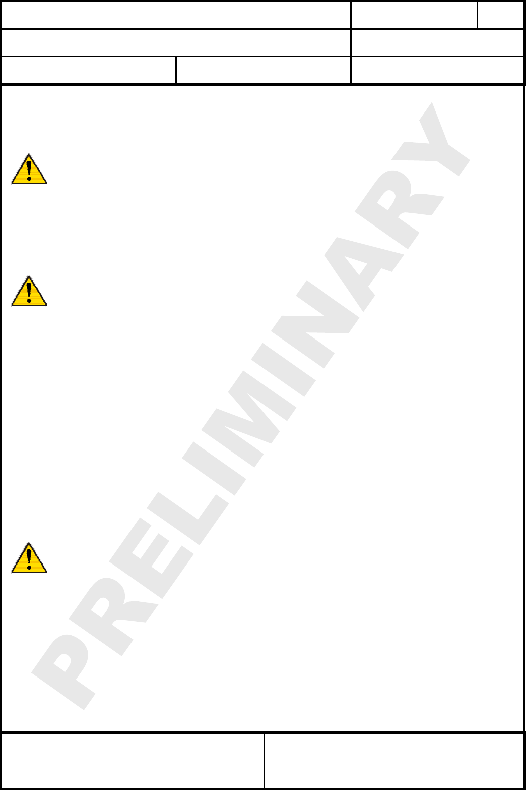
25. CAUTIONS
Warnungen
25.1. NOTES OF DESIGN
Designhinweise
(1) Please follow the condition written in this specification.
(2) This product should not be stressed when installed.
(3) Please keep this product the module away from heat.
(4) The supply voltage should not be exceeding or reverse, and should not carry noise
and spike.
(5) Please keep this product away from other high frequency circuits.
(6) Please follow the condition written in this interface specification, about the control
signals of this module.

CLASSIFICATION
Einstufung
PRODUCT SPECIFICATION
Produktspezifikation
No.
DS-8550-908-102
REV.
0.91
SUBJECT
Thema
Z-WAVE MODULE
Z-Wave Modul
PAGE
Seite
20 of 28
CUSTOMER’S CODE
PAN8550
PANASONIC’S CODE
ENW99A01xyz
DATE
Datum
02.06.2006
PANASONIC ELECTRONIC DEVICES
EUROPE GMBH
High Frequency Products Business Group
- Wireless Modules -
APPROVED
genehmigt
CHECKED
geprüft
DESIGNED
erstellt
25.2. NOTES OF INSTALLATION
Verarbeitungshinweise
(1) Reflow soldering is possible for twice on the condition in chapter 17.
Please set up the temperature at the soldering portion of this product according to
this reflow profile.
(2) This product should not be stressed or vibrated when reflowed.
(3) Please keep the following conditions when you install this product for reparation by
hand soldering.
(4) Please do not wash this product.
(5) Please refer to the recommended pattern when designing a board.
25.3. NOTES OF USAGE CONDITIONS
Benutzerhinweise
(1) Please take measure against static electricity.
(2) Please do not use the fallen product.
(3) Please do not put on damage and dirt to the pin , and don't touch the electric
components.
(4) Please follow the condition written in the ratings , about the power supply
instruments applied to this product.
(5) Electrode peeling strength: Do not add pressure of more than 4.9N when soldered
on PCB
25.4. NOTES OF STORAGE
Lagerhinweise
(1) Storage period: Please check the adhesive strength of the embossed tape and
soldering after 6 months of storage.
(2) Please keep this product away from water, poisonous gas and corrosive gas.
(3) This product should not be stressed or shocked when transported.
(4) Please follow the specification when piling up the packed crate ( max. 10).
25.5. OTHER CAUTIONS
Weitere Hinweise
(1) This specification sheet is copyrighted. Please do not open it to the third party.
(2) Please do not use this product of our company for another purpose.
(3) Be sure to provide an appropriate fail-safe function on your product to prevent a
second damage that may be caused by the abnormal function or the failure of our
product.
(4) This product has not been manufactured with any ozone chemical controlled under
the Montreal Protocol.
(5) When you have any question or uncertainty , both of you and Panasonic sincerely
cope with it.
CLASSIFICATION
Einstufung
PRODUCT SPECIFICATION
Produktspezifikation
No.
DS-8550-908-102
REV.
0.91
SUBJECT
Thema
Z-WAVE MODULE
Z-Wave Modul
PAGE
Seite
21 of 28
CUSTOMER’S CODE
PAN8550
PANASONIC’S CODE
ENW99A01xyz
DATE
Datum
02.06.2006
PANASONIC ELECTRONIC DEVICES
EUROPE GMBH
High Frequency Products Business Group
- Wireless Modules -
APPROVED
genehmigt
CHECKED
geprüft
DESIGNED
erstellt
26. PACKAGING
Verpackung
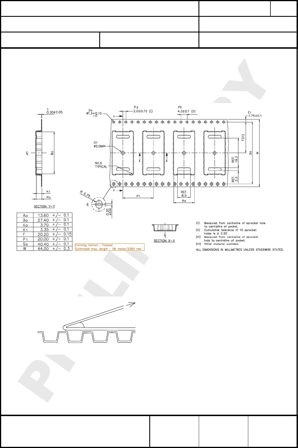
26.1. EMBOSSED TAPE / BLISTERGURT
(1) Dimension of the tape / Abmessungen des Gurtes (EIAJ-tbd)
(2) Cover tape reel strength / Abzugskräfte Blistergurt Deckfolie
Force direction
Speed = 300mm/min.
Cover tape reel strength
=0.098
~0.68N (10~70g)
= 10deg
CLASSIFICATION
Einstufung
PRODUCT SPECIFICATION
Produktspezifikation
No.
DS-8550-908-102
REV.
0.91
SUBJECT
Thema
Z-WAVE MODULE
Z-Wave Modul
PAGE
Seite
22 of 28
CUSTOMER’S CODE
PAN8550
PANASONIC’S CODE
ENW99A01xyz
DATE
Datum
02.06.2006
PANASONIC ELECTRONIC DEVICES
EUROPE GMBH
High Frequency Products Business Group
- Wireless Modules -
APPROVED
genehmigt
CHECKED
geprüft
DESIGNED
erstellt
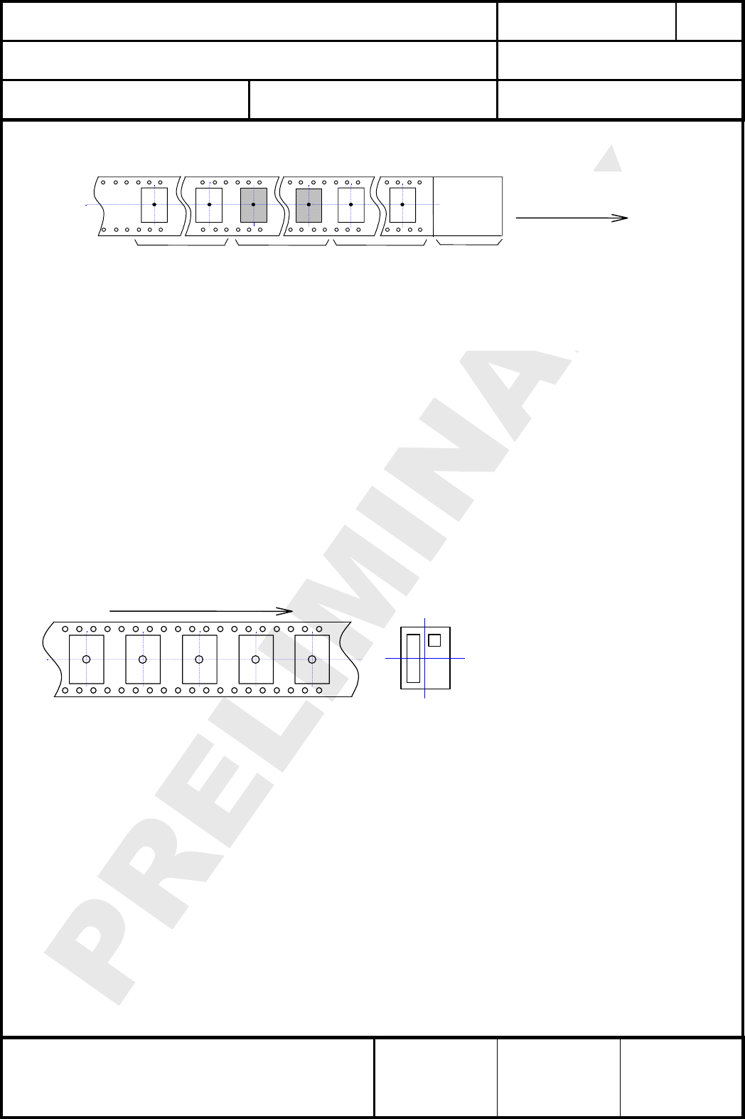
(3) Empty hollow / leere Taschen
Empty hollow in component packed area shall be less than two per reel and those hollows shall not
be consecutive.
Es dürfen minimal 2 leere Taschen im Bereich der Komponenten vorhanden sein, diese dürfen
aber nicht aufeinander folgen.
Component
packed area
Modulbereich
Empty hollow more
than 10pitch
Mehr als 10 leere
Taschen
Top cover tape
more t han 200mm
Deckfolie groesser als
200mm
Direct ion of feed
Vorschubrichtung
Empt y hollow more
t han 10 pitch
Mehr als 10 leere
Taschen
26.2. COMPONENT DIRECTION
Komponentenanordnung
Top cover tape shall not be found on reel holes and shall not stick out from reel.
Deckfolien darf nicht durch die Löcher der Spule und nicht außerhalb der Spule geführt werden.
1
6 7
12
(
to
p
view
)
Component direction
Komponentenrichtung
Part No.
Tape running direction
Laufrichtung des Bandes
Figure 1
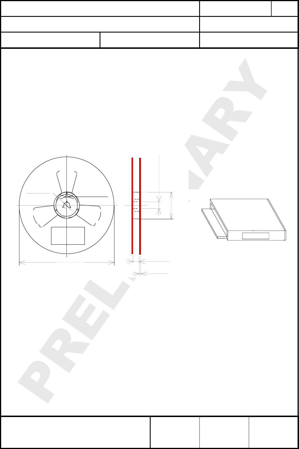
26.3. REEL DIMENSION
Abmaße der Rolle
(1) Quantity per reel : 500 pieces
Anzahl pro Rolle : 500 Stück
(2) Marking : Customer’s part No. / Quantity / Lot No. and Our part# with bar-code
shall be on the reel.
Kennzeichnung : Kundennummer / Anzahl / Losnummer und unsere
Komponentennummer als Barcode wird auf die Rolle gedruckt
Refer to figure 2
Bezugnehmend zur Zeichnung 2
CLASSIFICATION
Einstufung
PRODUCT SPECIFICATION
Produktspezifikation
No.
DS-8550-908-102
REV.
0.91
SUBJECT
Thema
Z-WAVE MODULE
Z-Wave Modul
PAGE
Seite
23 of 28
CUSTOMER’S CODE
PAN8550
PANASONIC’S CODE
ENW99A01xyz
DATE
Datum
02.06.2006
PANASONIC ELECTRONIC DEVICES
EUROPE GMBH
High Frequency Products Business Group
- Wireless Modules -
APPROVED
genehmigt
CHECKED
geprüft
DESIGNED
erstellt
26.4. PACKAGE
Umverpackung
(1) Package box : 1 or 2 reel (depends on quantity)
Paketbox.: 1 oder 2 Rollen (abhängig von der Liefermenge)
(2) Marking : Customer’s part No. / Quantity / Lot No. and Our part# with
bar-code shall be on the package box.
Kennzeichnung : Kundennummer / Anzahl / Losnummer und unsere
Komponentennummer als Barcode wird auf die
Verpackung gedruckt
Refer to figure 2 and 3
Bezugnehmend zur Zeichnung 2 und 3
φ13 +/-1 2 +/-0.5
φ330
Marking
33.5 +/-1.0
2.0 +/-0.2
φ13 +/-0.5
φ80 +/-2
Figure 2
Markin
g
Figure 3
CLASSIFICATION
Einstufung
PRODUCT SPECIFICATION
Produktspezifikation
No.
DS-8550-908-102
REV.
0.91
SUBJECT
Thema
Z-WAVE MODULE
Z-Wave Modul
PAGE
Seite
24 of 28
CUSTOMER’S CODE
PAN8550
PANASONIC’S CODE
ENW99A01xyz
DATE
Datum
02.06.2006
PANASONIC ELECTRONIC DEVICES
EUROPE GMBH
High Frequency Products Business Group
- Wireless Modules -
APPROVED
genehmigt
CHECKED
geprüft
DESIGNED
erstellt
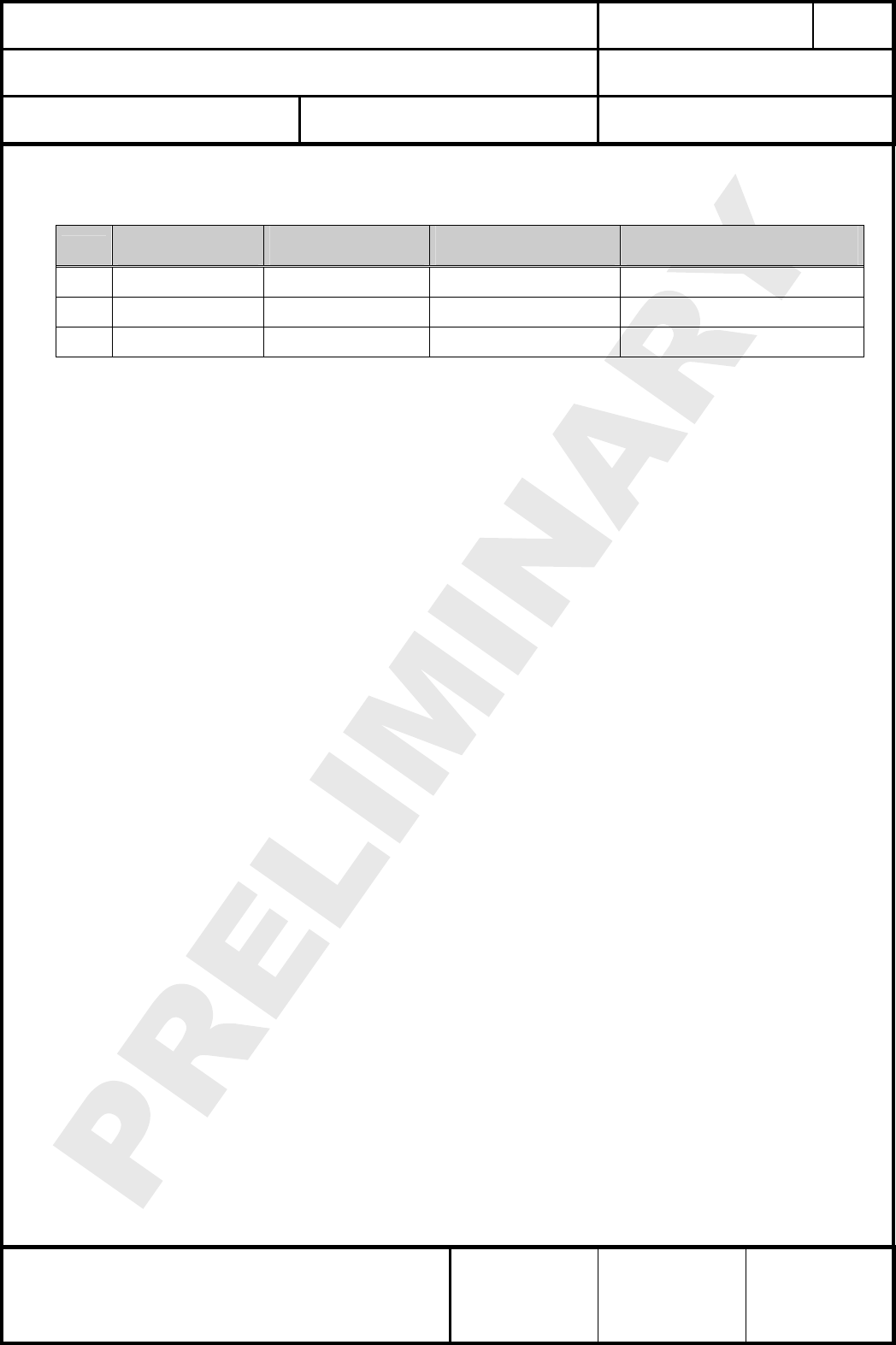
27. ORDERING INFORMATION
Bestellinformationen
Ordering part number Description MOQ (1)
ENW9ZA01N2D(2) Engineering Sample PAN8550
908,42MHz and plug connector 1
ENW9ZA01A3D(2) Engineering Sample PAN8550
908,42MHz and ceramic antenna 1
ENW9ZA01N2C(2) Engineering Sample PAN8550
868,42MHz and plug connector 1
ENW9ZA01A3C(2) Engineering Sample PAN8550
868,42MHz and ceramic antenna 1
Notes:
(1) Abbreviation for Minimum Order Quantity (MOQ). If this module is in mass production the standard
MOQ are 500 pieces, fewer only on customer demand.
(2) The “Z” in the ordering part number indicates the engineering sample status. If this module is in
mass production the “Z” will change to “9”.

CLASSIFICATION
Einstufung
PRODUCT SPECIFICATION
Produktspezifikation
No.
DS-8550-908-102
REV.
0.91
SUBJECT
Thema
Z-WAVE MODULE
Z-Wave Modul
PAGE
Seite
25 of 28
CUSTOMER’S CODE
PAN8550
PANASONIC’S CODE
ENW99A01xyz
DATE
Datum
02.06.2006
PANASONIC ELECTRONIC DEVICES
EUROPE GMBH
High Frequency Products Business Group
- Wireless Modules -
APPROVED
genehmigt
CHECKED
geprüft
DESIGNED
erstellt
28. ROHS DECLARATION
RoHS-Erklärung
Declaration of environmental compatibility for supplied products:
Hereby we declare to our best present knowledge based on declaration of our suppliers that this
product do not contain by now the following substances which are banned by Directive 2002/95/EC
(RoHS) or if contain a maximum concentration of 0,1% by weight in homogeneous materials for
• Lead and lead compounds
• Mercury and mercury compounds
• Chromium (VI)
• PBB (polybrominated biphenyl) category
• PBDE (polybrominated biphenyl ether) category
And a maximum concentration of 0,01% by weight in homogeneous materials for
• Cadmium and cadmium compounds
29. DATA SHEET STATUS
Datenblatt Status
This data sheet contains data from the PRELIMINARY specification. Supplementary data will be
published at a later date. Panasonic reserves the right to change the specification without notice, in
order to improve the design and supply the best possible product.
Please consult the most recently issued data sheet before initiating or completing a design.
30. RELATED DOCUMENTS
Mitgeltende Dokumente
[1] Data Sheet ZW0201 General Release Version 4.3 23. Feb 2005
[2] Data Sheet Antenna Johanson P/N 0920AT50A080 09/15/05
[3] Data Sheet UFL Series Hirose P/N U.FL-R-SMT 2004.2
CLASSIFICATION
Einstufung
PRODUCT SPECIFICATION
Produktspezifikation
No.
DS-8550-908-102
REV.
0.91
SUBJECT
Thema
Z-WAVE MODULE
Z-Wave Modul
PAGE
Seite
26 of 28
CUSTOMER’S CODE
PAN8550
PANASONIC’S CODE
ENW99A01xyz
DATE
Datum
02.06.2006
PANASONIC ELECTRONIC DEVICES
EUROPE GMBH
High Frequency Products Business Group
- Wireless Modules -
APPROVED
genehmigt
CHECKED
geprüft
DESIGNED
erstellt
31. REGULATORY INFORMATION
31.1. FCC NOTICE
The device PAN8550, including the ceramic antenna (ENW99A01A3D) complies with Part 15
of the FCC Rules. The device meets the requirements for modular transmitter approval as
detailed in FCC public Notice DA00-1407.transmitter
Operation is subject to the following two conditions: (1) This device may not cause harmful
interference, and (2) This device must accept any interference received, including
interference that may cause undesired operation.
31.2. CAUTION
The FCC requires the user to be notified that any changes or modifications made to this
device that are not expressly approved by Panasonic Electronic Devices Europe GmbH may
void the user's authority to operate the equipment.
This equipment has been tested and found to comply with the limits for a Class B digital
device, pursuant to Part 15 of the FCC Rules. These limits are designed to provide
reasonable protection against harmful interference in a residential installation. This equipment
generates, uses and can radiate radio frequency energy and, if not installed and used in
accordance with the instructions, may cause harmful interference to radio communications.
However, there is no guarantee that interference will not occur in a particular installation. If
this equipment does cause harmful interference to radio or television reception, which can be
determined by turning the equipment off and on, the user is encouraged to try to correct the
interference by one or more of the following measures:
• Reorient or relocate the receiving antenna.
• Increase the separation between the equipment and receiver.
• Connect the equipment into an outlet on a circuit different from that to which the
receiver is connected.
• Consult the dealer or an experienced radio/TV technician for help
31.3. LABELING REQUIREMENTS
The Original Equipment Manufacturer (OEM) must ensure that FCC labeling requirements
are met. This includes a clearly visible label on the outside of the OEM enclosure specifying
the appropriate Panasonic FCC identifier for this product as well as the FCC Notice above.
The FCC identifier are FCCID: T7VPAN8550. This FCC identifier is only valid for the part
number ENW99A01A3D (PAN8550 with mounted ceramic antenna). For details, please see
the chapter 27. Ordering Information.
The EUT is labelled with FCC ID: T7VPAN8550. This Label must be visible for the user in the
end product. If the module is inside of an end product, the label will not be visible. In this case
the end product will be labelled exterior with "Contains FCC ID: T7VPAN8550"
Part 2.925 (a) (1) describes "...The FCC Identifier shall be preceded by the term FCC ID in
capital letters on a single line, ....". Due to the limited size, we have 2 lines and could not fulfill
this rule. Otherwise the letters are too small and could not be readable, therefore we made
this compromise.
CLASSIFICATION
Einstufung
PRODUCT SPECIFICATION
Produktspezifikation
No.
DS-8550-908-102
REV.
0.91
SUBJECT
Thema
Z-WAVE MODULE
Z-Wave Modul
PAGE
Seite
27 of 28
CUSTOMER’S CODE
PAN8550
PANASONIC’S CODE
ENW99A01xyz
DATE
Datum
02.06.2006
PANASONIC ELECTRONIC DEVICES
EUROPE GMBH
High Frequency Products Business Group
- Wireless Modules -
APPROVED
genehmigt
CHECKED
geprüft
DESIGNED
erstellt
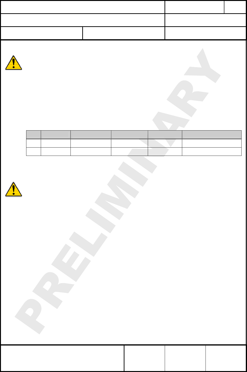
31.4. ANTENNA WARNING
The related part number for this device is ENW99A01N2D (PAN8550 with mounted
connector). For details, please see the chapter 27. Ordering Information. This device will be
tested with an UFL connector from company Hirose and with the antennas listed below.
When integrated in the OEMs product, these fixed antennas require installation preventing
end-users from replacing them with non-approved antennas. Any antenna not in the following
table must be tested to comply with FCC Section 15.203 for unique antenna connectors and
Section 15.247 for emissions. The FCC identifier for this device will be available, after a first
measurement with an approved antenna.
31.5. APPROVED ANTENNA LIST
Note: We are able to qualify your antenna and will add to this list as that process is completed.
Item Part Number Manufacturer Frequency Band Type Gain (dBi)
1
2
31.6. RF EXPOSURE PAN8550
To comply with FCC RF Exposure requirements, the Original Equipment Manufacturer (OEM)
must ensure that the approved antenna in the previous table must be installed and/or
configured to operate with a separation distance of 2.5cm or more from all persons to satisfy
RF Exposure compliance.
The preceding statement must be included as a CAUTION statement in manuals for products
operating with the approved antennas in the previous table to alert users on FCC RF
Exposure compliance.
Any notification to the end user of installation or removal instructions about the integrated
radio module is not allowed.
The radiated output power of PAN8550 with mounted ceramic antenna
(FCC ID: T7VPAN8550) is far below the FCC radio frequency exposure limits. Nevertheless,
the PAN8550 shall be used in such a manner that the potential for human contact during
normal operation is minimized.
The EUT meets the requirements of FCC section 15.249, even if the EUT transmitted at the
maximum allowed field strength (50,000 uV/m),which the equivalent e.i.r.p would be
0.75 mW. End users may not be provided with the module installation instructions. OEM
integrators and end users must be provided with transmitter operating conditions for satisfying
RF exposure compliance.
CLASSIFICATION
Einstufung
PRODUCT SPECIFICATION
Produktspezifikation
No.
DS-8550-908-102
REV.
0.91
SUBJECT
Thema
Z-WAVE MODULE
Z-Wave Modul
PAGE
Seite
28 of 28
CUSTOMER’S CODE
PAN8550
PANASONIC’S CODE
ENW99A01xyz
DATE
Datum
02.06.2006
PANASONIC ELECTRONIC DEVICES
EUROPE GMBH
High Frequency Products Business Group
- Wireless Modules -
APPROVED
genehmigt
CHECKED
geprüft
DESIGNED
erstellt
32. GENERAL INFORMATION
Allgemeine Informationen
© Panasonic Electronic Devices Europe GmbH 2005.
All rights reserved.
This product description does not lodge the claim to be complete and free of mistakes.
Please contact the related product manager in every case.
If we deliver samples to the customer, these samples have the status Engineering Samples.
This means, the design of this product is not yet concluded. Engineering Samples may be
partially or fully functional, and there may be differences to be published Data Sheet.
Engineering Samples are not qualified and are not to be used for reliability testing or series
production.
Disclaimer:
Customer acknowledges that samples may deviate from the Data Sheet and may bear defects
due to their status of development and the lack of qualification mentioned above.
Panasonic rejects any liability or product warranty for Engineering Samples. In particular,
Panasonic disclaims liability for damages caused by
• the use of the Engineering Sample other than for Evaluation Purposes, particularly the
installation or integration in an other product to be sold by Customer,
• deviation or lapse in function of Engineering Sample,
• improper use of Engineering Samples.
Panasonic disclaimes any liability for consequential and incidental damages.
In case of any questions, please contact your local sales partner or the related product
manager.
33. LIFE SUPPORT POLICY
Politik für Lebenserhaltungssysteme
This Panasonic product is not designed for use in life support appliances, devices, or systems
where malfunction can reasonably be expected to result in a significant personal injury to the
user, or as a critical component in any life support device or system whose failure to perform
can be reasonably expected to cause the failure of the life support device or system, or to affect
its safety or effectiveness. Panasonic customers using or selling these products for use in such
applications do so at their own risk and agree to fully indemnify Panasonic for any damages
resulting.