Panasonic Healthcare 9TB097DSS S-AIT Tape Drive Unit User Manual S AIT 1
Panasonic Healthcare Co., Ltd. S-AIT Tape Drive Unit S AIT 1
users manual
S-AIT Tape Drive Unit
S-AIT is an abbreviation of Super Advanced Intelligent Tape
Installation Manual
LKM-A111-BC / LKM-A121-BC
LKM-A111-BD / LKM-A121-BD
LMQT00623
Rev. A

LKM-A111-BC / LKM-A111-BD
IMPORTANT SAFETY NOTICE ................................................................ 2
WICHTIGE SICHERHEITSHINWEISE – German – ..................................... 4
Introduction ....................................................................................................... 6
About LKM-A111-B Tape Drive..................................................................... 6
Product Features ............................................................................................. 6
System Requirements ...................................................................................... 7
Kit Contents ( attached ) ................................................................................. 7
Precautions ..................................................................................................... 8
Parts and Functions ............................................................................... 9
Front View ....................................................................................................... 9
Rear View ....................................................................................................... 10
Installation ........................................................................................................ 11
Option Switches (DIP Switch) ....................................................................... 11
Connecting ...................................................................................................... 11
Table of Contents

LKM-A121-BC / LKM-A121-BD
IMPORTANT SAFETY NOTICE ...............................................................14
WICHTIGE SICHERHEITSHINWEISE – German – .................................... 16
Introduction ...................................................................................................... 18
About LKM-A121-B Tape Drive.................................................................... 18
Product Features .............................................................................................. 19
System Requirements ..................................................................................... 20
Kit Contents ( attached ) ................................................................................ 20
Precautions ...................................................................................................... 21
Parts and Functions ..............................................................................22
Front View ...................................................................................................... 22
Rear View ....................................................................................................... 23
Installation ........................................................................................................ 24
FC Connection/Setting the LOOP ID ............................................................ 24
Arbitrated Loop Physical Addresses (AL_PA) and Loop IDs ....................... 25
Option Switches (DIP Switch) ....................................................................... 26
Connecting .............................................................................................. 26

Operation
( for Model LKM-A111-BC / LKM-A111-BD / LKM-A121-BC / LKM-A121-BD ) .......... 27
LED Indication for Drive Status .................................................................... 27
Drive Operation .............................................................................................. 28
Interface Implementation
( for Model LKM-A111-BC / LKM-A111-BD / LKM-A121-BC / LKM-A121-BD ) .......... 29
Supported SCSI Messages .............................................................................. 29
Supported SCSI Commands .......................................................................... 29
Maintenance
( for Model LKM-A111-BC / LKM-A111-BD / LKM-A121-BC / LKM-A121-BD ) .......... 30
Filter Exchanging ............................................................................................ 31
Specification
( for Model LKM-A111-BC / LKM-A111-BD / LKM-A121-BC / LKM-A121-BD ) .......... 32
Cartridge Tape Performance ....................................................................... 32
General Performance ....................................................................................... 32
Environmental Conditions............................................................................... 32
Appendix
( for Model LKM-A111-BC / LKM-A111-BD / LKM-A121-BC / LKM-A121-BD ) .......... 33
Mounting the Drive Unit to Rack .................................................................... 33
Anhang – German –
( für den Typ LKM-A111-BC / LKM-A111-BD / LKM-A121-BC / LKM-A121-BD ) ....... 34
Montage ........................................................................................................... 34
Installation Manual
LKM-A111-BC / LKM-A111-BD

2LKM-A111-BC / LKM-A111-BD
IMPORTANT SAFETY NOTICE
NOTICE
(1) You may not reproduce or transcribe any part of this publication without permission.
(2) We reserve the right to revise this document at any time without notice.
(3) If you have any questions about this document, contact your sales representative.
SAFETY NOTICE
(1) To prevent fire or electric shock, do not expose this appliance to rain or moisture.
(2) To avoid electric shock, do not attempt to disassemble the cabinet.
(3) For pluggable equipment, the socket-outlet shall be installed near the equipment and shall
be easily accessible.
FEDERAL COMMUNICATIONS COMMISSION (FCC) RADIO FREQUENCY
INTERFERENCE STATEMENT
Class B Computing Device
NOTE : This equipment has been tested and found to comply with the limits for a Class B
digital device, pursuant to part 15 of the FCC Rules. These limits are designed to provide
reasonable protection against harmful interference in a residential installation. This
equipment generates, uses and can radiate radio frequency energy and , if not installed and
used in accordance with the instructions, may cause harmful interference to radio
communications. However, there is no guarantee that interference will not occur in
a particular installation. If this equipment does cause harmful interference to radio or
television reception, which can be determined by turning the equipment off and on, the user
is encouraged to try to correct the interference by one or more of the following
measures :
- - Reorient or relocate the receiving antenna.
- - Increase the separation between the equipment and receiver.
- - Connect the equipment into an outlet on a circuit different from that to which the
receiver is connected.
- - Consult the dealer or an experienced radio/TV technician for help.
FCC WARNING : Changes or modifications not expressly approved by the party
responsible for compliance could void the user’s authority to operate the equipment.
CAUTION :
Use shielded connecting cables in order to meet FCC emission limits and also to prevent
interference to nearby radio and television reception.
IMPORTANT :
If the power cord is not attached when purchasing this equipment, consult
with your dealer,etc.
" Use only Safety Licensed Power Cord on the relevant regulations. "
A certified power cord is to be used with this equipment. For a rated current up to 6 A,
a type not lighter than H05VV-F3G 0.75 mm2 or H05VVH2-F 3G 0.75 mm2 shall be used.
This product can be used with the attached power cord only.
For Model LKM-A111-BC
For USA (Model LKM-A111-BC only)
For Model LKM-A111-BD

LKM-A111-BC / LKM-A111-BD 3
IMPORTANT SAFETY INSTRUCTIONS
1. Read all of these instructions.
2. Save these instructions for later use.
3. Follow all warnings and instructions marked on the product.
4. Unplug this product from the wall outlet before cleaning. Do not use liquid cleaners
or aerosol cleaners. Use a damp cloth for cleaning.
5. Do not use this product near water.
6. Do not place this product on an unstable rack, cart, stand, or table. The product may
fall, causing serious damage to the product.
7. This product should be operated from the type of power source indicated on the
marking label. If you are not sure of the type of power available, consult your
dealer or local power company.
8. This product is equipped with a 3-wire grounding type plug, a plug having a third
(grounding) pin. This plug will only fit into a grounding-type power outlet. This is a safety
feature. If you are unable to insert the plug into the outlet, contact your
electrician to replace your obsolete outlet. Do not defeat the purpose of the
grounding-type plug.
9. Do not allow anything to rest on the power cord. Do not locate this product where
persons will walk on the cord.
10. If an extension cord is used with this product, make sure that the total of the
ampere ratings on the products plugged into the extension cord do not exceed the
extension cord ampere rating. Also, make sure that the total of all products
plugged into the wall outlet does not exceed 15 amperes.
11. Never push objects of any kind into this product through cabinet slots as they may
touch dangerous voltage points or short out parts that could result in a risk of fire
or electric shock. Never spill liquid of any kind on the product.
12. Do not attempt to service this product yourself, as opening or removing covers may
expose you to dangerous voltage points or other risks. Refer all servicing to
service personnel.
13. Unplug this product from the wall outlet and refer servicing to qualified service
personnel under the following conditions:
A. When the power cord or plug is damaged or frayed.
B. If liquid has been spilled into the product.
C. If the product has been exposed to rain or water.
D. If the product does not operate normally when the operating instructions are
followed. Adjust only those controls that are covered by the operating
instructions since improper adjustment of other controls may result in damage
and will often require extensive work by a qualified technician to restore the
product to normal operation.
E. If the product has been dropped or the cabinet has been damaged.
F. If the product exhibits a distinct change in performance, indicating a need for
service.
14. Slots and openings in the cabinet and back or bottom are provided for ventilation and
to ensure reliable operation of the product and to protect it from overheating. These
openings must not be blocked or covered.
4LKM-A111-BC / LKM-A111-BD
VORSICHT
Diese Ausrüstung erfüllt die Europäischen EMC-Bestimmungen für die
Verwendung in folgender / folgenden Umgebung(en):
• Wohngegenden
• Gewerbegebiete
• Leichtindustriegebiete
(Diese Ausrüstung erfüllt die Bestimmungen der Norm EN55022, Klasse B.)
WICHTIGE SICHERHEITSHINWEISE
HINWEISE
(1) Ohne Genehmigung dürfen keine Auszüge dieser Veröffentlichung reproduziert oder
übertragen werden.
(2) Wir behalten uns das Recht vor, dieses Dokument jederzeit ohne Vorankündigung zu
überarbeiten.
(3) Wenn Sie Fragen zu diesem Dokument haben, wenden Sie sich an Ihren
Verkaufsrepräsentanten.
SICHERHEITSHINWEISE
(1) Setzen Sie dieses Gerät zur Vermeidung eines Brandes oder elektrischen Schlages weder
Regen noch Feuchtigkeit aus.
(2) Versuchen Sie zur Vermeidung eines elektrischen Schlages nicht, das Gehäuse
auseinander zu bauen.
(3) Bei steckbaren Geräten sollte die Steckdose in der Nähe der Geräte installiert werden
und leicht zugänglich sein.
WICHTIG :
Wenden Sie sich an Ihren Händler usw., wenn das Netzkabel beim Kauf des Gerätes nicht
montiert ist.
"Verwenden Sie ausschließlich sicherheitsgeprüfte, den geltenden gesetzlichen
Bestimmungen entsprechende Netzkabel."
Mit diesem Gerät ist ein zertifiziertes Netzkabel zu verwenden. Für eine zulässige
Stromstärke von bis zu 6 A sollte ein Netzkabeltyp verwendet werden, der nicht leichter ist
als H05VV-F3G 0,75 mm2 oder H05VVH2-F 3G 0,75 mm2.
– German –
Dieses Gerät kann nur mit dem beigefügten Netzkabel betrieben werdern.
Für den Typ LKM-A111-BC
Für den Typ LKM-A111-BD

LKM-A111-BC / LKM-A111-BD 5
1. Lesen Sie sich alle hier aufgeführten Anweisungen durch.
2. Bewahren Sie diese Anweisungen für eine spätere Verwendung auf.
3. Befolgen Sie alle auf dem Produkt gekennzeichneten Warnungen und Anweisungen.
4. Trennen Sie dieses Produkt vor der Reinigung von der Wandsteckdose ab. Verwenden
Sie keine Flüssigreiniger oder Aerosolreiniger. Reinigen Sie das Gerät mit einem
feuchten Tuch.
5. Verwenden Sie dieses Produkt nicht in der Nähe von Wasser.
6. Stellen Sie dieses Produkt nicht auf einem instabilen Rack, Wagen, Ständer oder Tisch
auf. Das Produkt könnte unter Umständen herunter fallen und ernsthafte
Beschädigungen davontragen.
7. Dieses Produkt sollte von der auf dem Leistungsaufkleber aufgeführten
Spannungsquelle betrieben werden. Wenn Sie nicht sicher sind, welche Spannung
verfügbar ist, wenden Sie sich an Ihren Händler oder an Ihr örtliches
Energieversorgungsunternehmen.
8. Dieses Gerät ist mit einem 3-adrigen Erdungsstecker ausgestattet - einem Stecker mit
einem dritten (Erdungs-) Stift. Dieser Stecker passt nur in eine Erdungssteckdose.
Hierbei handelt es sich um eine Sicherheitseinrichtung. Wenn sich der Stecker nicht in
die Steckdose einstecken lässt, beauftragen Sie bitte einen Elektriker mit dem
Austausch Ihrer veralteten Steckdose. Machen Sie den Zweck des Erdungssteckers
nicht zunichte.
9. Lassen Sie keinerlei Gegenstände auf dem Netzkabel stehen. Stellen Sie dieses
Produkt nicht an einem Ort auf, an dem Personen über das Kabel laufen würden.
10. Stellen Sie bei der Verwendung eines Verlängerungskabels sicher, dass die
Gesamtampereleistung der an das Verlängerungskabel angeschlossenen Geräte
nicht die Ampereleistung des Verlängerungskabels überschreitet. Stellen Sie darüber
hinaus sicher, dass alle an die Wandsteckdose angeschlossenen Geräte 15 Ampere
nicht überschreiten.
11. Schieben Sie keinerlei Gegenstände über die Gehäuseschlitze in dieses Produkt, da
diese gefährliche Spannungspunkte berühren oder Teile kurzschließen könnten.
Beides könnte sowohl einen Brand als auch einen elektrischen Schlag zur Folge
haben.
12. Versuchen Sie nicht, dieses Produkt selber zu warten, da Sie sich durch das Öffnen
und Entfernen von Abdeckungen gefährlichen Spannungspunkten oder anderen
Gefahren aussetzen würden. Überlassen Sie sämtliche Wartungsarbeiten dem
Kundendienstpersonal.
13. Unter den nachfolgenden Umständen sollten Sie dieses Produkt von der
Wandsteckdose abtrennen und qualifiziertem Kundendienstpersonal zur Wartung
übergeben:
A. Wenn das Netzkabel oder der Stecker beschädigt oder abgenutzt sind.
B. Wenn Flüssigkeit in das Produkt gelangt ist.
C. Wenn das Produkt Regen oder Feuchtigkeit ausgesetzt worden ist.
D. Wenn das Gerät trotz Befolgen der Bedienungsanleitung nicht normal funktioniert.
Stellen Sie nur die in der Bedienungsanleitung beschriebenen Regler ein, da eine
falsche Einstellung anderer Regler Beschädigungen verursachen kann, und die
Wiederherstellung des Normalbetriebes des Produktes durch einen qualifizierten
Techniker einen hohen Arbeitsaufwand erforderlich machen würde.
E. Wenn das Gerät heruntergefallen ist oder das Gehäuse beschädigt wurde.
F. Wenn sich die Leistungsfähigkeit des Gerätes deutlich verändert, was ein
Anzeichen dafür ist, dass eine Wartung erforderlich wird.
14. Die sich im Gehäuse, auf der Rückseite und der Unterseite des Gerätes befindlichen
Schlitze und Öffnungen dienen der Ventilation und stellen einen zuverlässigen Betrieb
des Produktes sicher. Darüber hinaus schützen sie das Gerät vor Überhitzung. Diese
Öffnungen dürfen weder blockiert noch abgedeckt werden.
WICHTIGE SICHERHEITSANWEISUNGEN
– German –
6LKM-A111-BC / LKM-A111-BD
Product Features
Introduction
LKM-A111-B
Data Capacity 500 GByte uncompressed (with SAIT-1 600 m tape)
1300 GByte compressed * (with SAIT-1 600 m tape)
Transfer Rate 30 MByte/s uncompressed
(sustained) 78 MByte/s compressed *
*This is assuming 2.6 : 1 compression ratio.
Product Features
• Supported Format : SAIT-1
• Not compatible with the LTO, DLT and SDLT format tapes
• Burst Transfer Rate –12 MBytes/s Asynchronous
–160 MByte/s Synchronous
• 72 MByte Buffer Memory
• 5” form factor
• Embedded SCSI Interface
(Ultra160 Wide LVD/SE SCSI)
• Supports Variable or Fixed Record Length
• Supports SCSI Disconnection/Arbitration
• Read After Write (RAW) On and Off selectable
• Fragment Rewrite Function
• Three levels of Error Correction Code (ECC)
• High Speed search
• Random Read, Append Write
About LKM-A111-B Tape Drive
The LKM-A111-B drive is a high capacity data storage device using Super Advanced
Intelligent tape (S-AIT) technology. The LKM-A111-B drive achieves high data reliability
through Read-After-Write, an additional level of Error Correction Code, and other features.
The LKM-A111-B drive stores data on tape using a standard format called S-AIT (Super
Advanced Intelligent Tape) and ALDC (Adaptive Lossless Data Compression) formats.

LKM-A111-BC / LKM-A111-BD 7
System Requirements
• SCSI Interface Card (Recommended)
' SCSI Card 29160 ' series (by Adaptec)
Note: This product is NOT supported with other SCSI Interface or
PCMCIA card than the above Card.
• SCSI Interface Cable (Recommended)
ACK-LVD-1M(3M)-U320 (by Adaptec)
• Cartridge-tape (Recommended)
LKM-SA1-500 ( Panasonic )
• Cleaning Tape (Recommended)
LKM-SA1-CL ( Panasonic )
• Backup Software (Recommended)
' Brightstor ARCserve Backup v9 ' or ' Brightstor Enterprise Backup '
(by Computer Associates)
' NetVault ' (by BakBone Software)
Note : The actually System Requirements for backup depend on your
using Backup software.
For details, refer to the manual of each Backup software.
Kit Contents ( attached )
• S-AIT Tape Drive Unit
• Power Cord ( Model LKM-A111-BC only )
• Terminator
• Installation Manual (this book)
• Filter Kit ( for Exchange )
• Cartridge-tape (1 pcs.)
• Cleaning Tape (1 pcs.)
• Warranty Card (with Registration Card)
8LKM-A111-BC / LKM-A111-BD
Precautions
Installation
Avoid placing the drive in a location subject to:
-high humidity
-high temperature
-mechanical shock and vibration
-direct sunlight
Operation
•Do not move the drive while it is operating. It may cause malfunction.
•Avoid exposing the drive to sudden changes from a low to high in temperature.
This may cause water condensation to collect inside the drive. If the ambient
temperature changes suddenly in transit, wait for more than four hours before
turning on the drive. If you attempt to operate the drive immediately after a sudden
increase in temperature, a malfunction may occur.
•Turning off the power to the drive while it is writing to tape may cause the tape to
become unreadable. All previously negotiated parameters will be lost, whenever
power to the drive is cycled.
•Upon execution of the hardware reset hole, the driver will be reset and there is a
risk of lost and unreadable data. Thus, please do not use the hole other than repair
purposes.
Transportation
•Keep the original packing materials to facilitate transportation of the drive.
•Always remove the tape before moving the drive. After removing the drive from the
computer, repack the drive into its original packing.
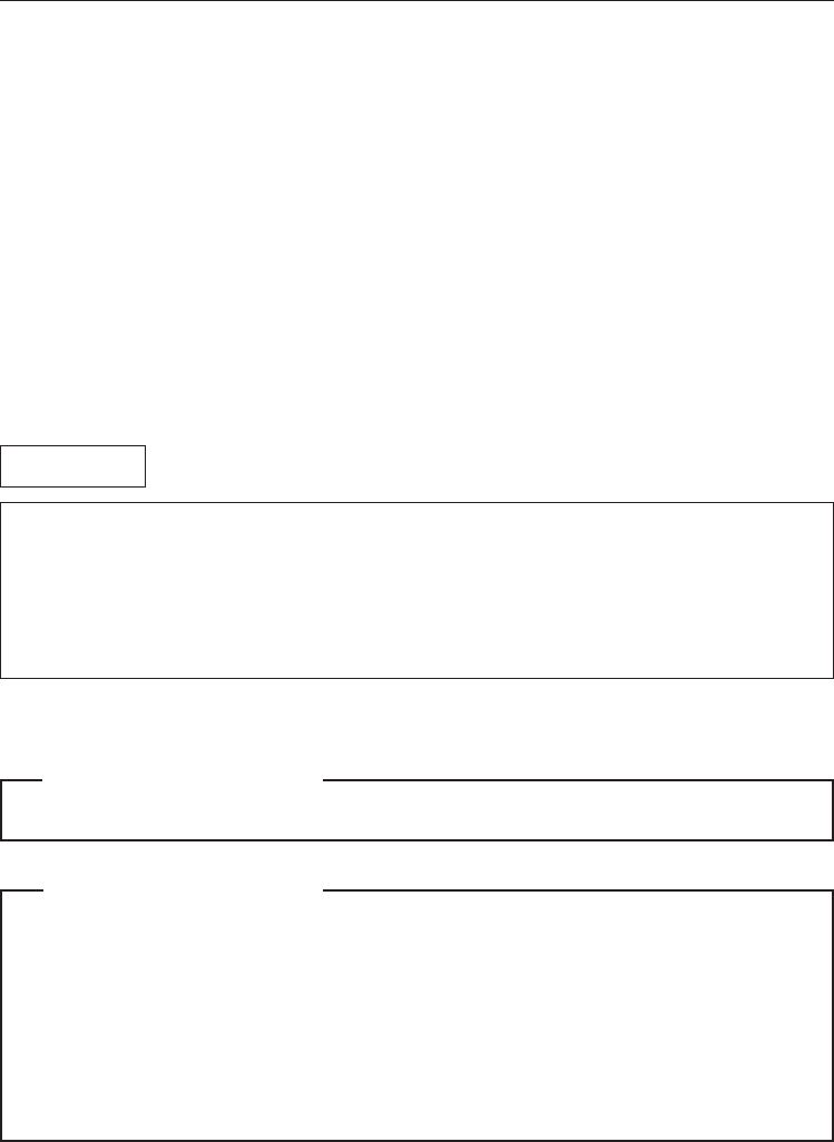
Notice of SCSI Termination
•The LKM-A111-B conforms to the Microsoft PC97 standard which requires the
external (enclosed) drive to be terminated with an external terminator.
Microsoft PC97 SCSI requirements
SCSI peripherals must not terminate the bus. Both internal and external cable ends
are instead terminated by plug-in connectors.
68p cable
Host Computer
Wide SCSI
Example of SCSI set-up This drive
Terminator
LKM-A111-BC / LKM-A111-BD 9
Parts and Functions
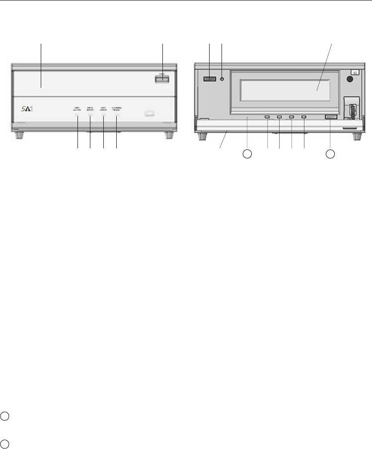
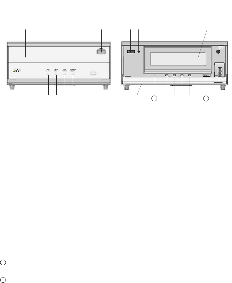
Front View
*1) For details of each LED indication status, refer to Page 27.
➀Front-Door
➁Front-Door Button
Push the button to open the Front-Door
➂ Tape Motion LED *1
Indicates the cartridge-tape operating status
➃ Drive Error LED *1
Indicates the drive error status
➄ Tape Error LED *1
Indicates the cartridge-tape error status
➅ Cleaning Request LED
Indicates the cleaning request status
➆ Power ON/OFF Switch
➇ Power LED
Lights up "Green" when the Tape Drive Unit is ON
➈ Cartridge-tape Inserting Door
➉ Air Flow Hole ( for absorption )
Not be blocked or covered to protect this Library from overheating
Hard Reset Hole
Hole for maintenance ( Not use generally )
Eject Button
Takes out the cartridge-tape
Front Door Closing Front Door Opening
➀➁
➂➃➄➅
➆➇➈
➉➂➃➄➅
11
12
11 12
10 LKM-A111-BC / LKM-A111-BD
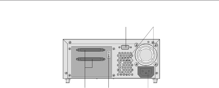
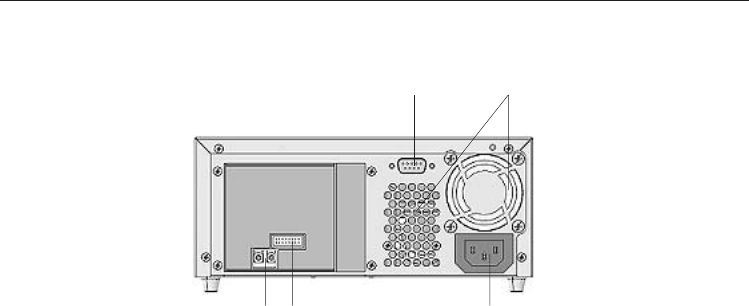
Rear View
➀Connector for maintenance
Not use generally
➁Fan / Air Flow Hole ( for release )
Not be blocked or covered to protect this Library from overheating
➂SCSI Interface Connector
Connect the SCSI interface cable ( 68-pin half pitch type )
➃SCSI ID Switch
Set up SCSI ID number (other number(0~15) than ones that have already used on your
SCSI bus)
Default ID number = " 0 "
➄Power Connector
Connect the power cord
➀➁
➄
➂➃
LKM-A111-BC / LKM-A111-BD 11
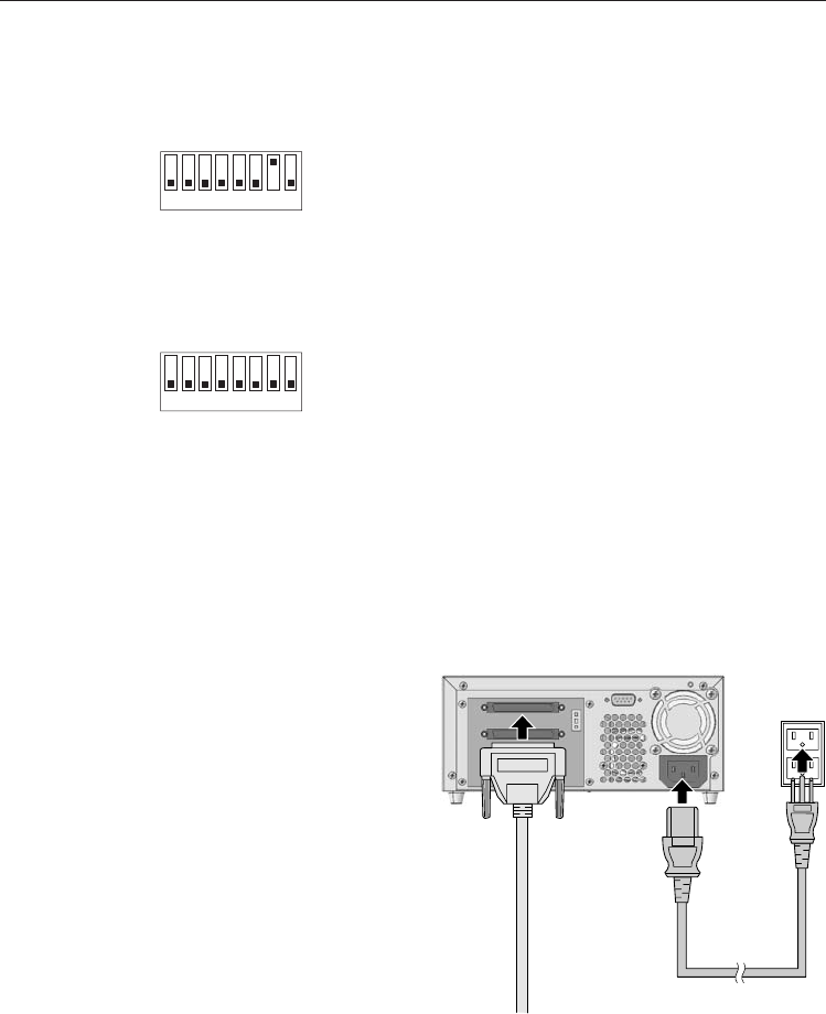
Option Switches ( DIP Switch )
SWB Setting
SW1 Reserved OFF
SW2 Reserved OFF
SW3 Reserved OFF
SW4 Reserved OFF
SW5 Reserved OFF
SW6 Reserved OFF
SW7 Reserved OFF
SW8 Reserved OFF
12345678
SWB
ON
OFF
SWA Setting
SW1 Custom-1 OFF
SW2 Custom-2 OFF
SW3 Custom-3 OFF
SW4 Custom-4 OFF
SW5 Reserved OFF
SW6 Reserved OFF
SW7 DC Control-1 ON
SW8 DC Control-2 OFF
12345678
SWA
ON
OFF
The dip switches locate on the bottom of this drive.
( Not operate these switches generally. )
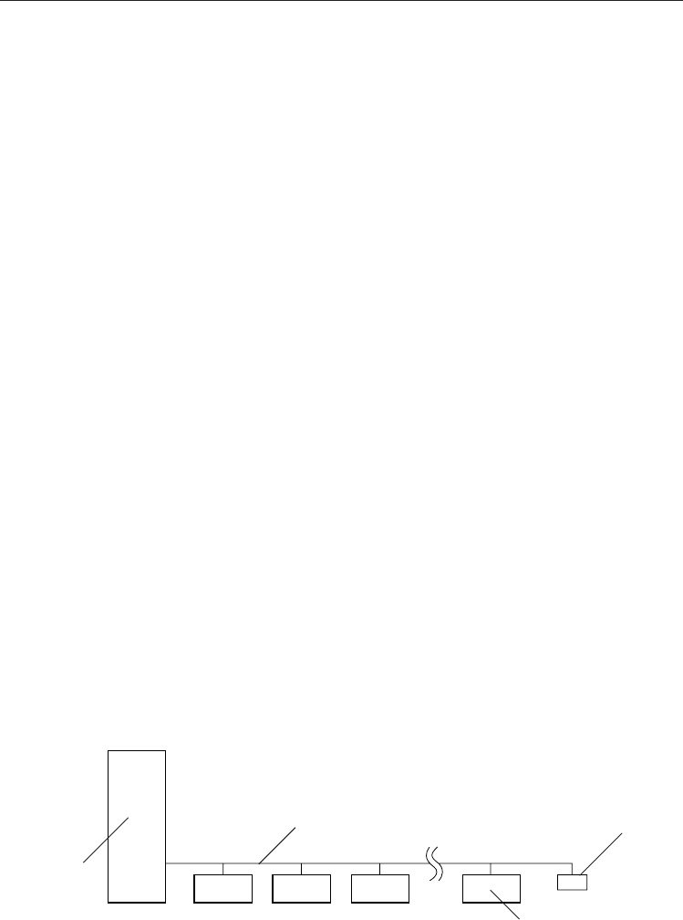
Connecting
After make sure that the system (Host PC) power switch is OFF, please connect
the S-AIT drive unit as follows.
1) Connect the SCSI interface cable to the
drive unit.
2) Connect the other end of the SCSI
interface cable to the system (host PC)
SCSI connector.
3) Connect the power cord to the drive unit
and the outlet with earth, and turn the
drive unit power ON.
4) Turn the system (host PC) power ON.
Note :
For details of SCSI termination, refer to
"Notice of SCSI Termination"
in Page 8.
SCSI Interface Cable
Power Cord
Installation
S-AIT Drive Unit (Rear Side)

12
Memo
Installation Manual
LKM-A121-BC / LKM-A121-BD

14 LKM-A121-BC / LKM-A121-BD
IMPORTANT SAFETY NOTICE
NOTICE
(1) You may not reproduce or transcribe any part of this publication without permission.
(2) We reserve the right to revise this document at any time without notice.
(3) If you have any questions about this document, contact your sales representative.
SAFETY NOTICE
(1) To prevent fire or electric shock, do not expose this appliance to rain or moisture.
(2) To avoid electric shock, do not attempt to disassemble the cabinet.
(3) For pluggable equipment, the socket-outlet shall be installed near the equipment and shall
be easily accessible.
FEDERAL COMMUNICATIONS COMMISSION (FCC) RADIO FREQUENCY
INTERFERENCE STATEMENT
Class B Computing Device
NOTE : This equipment has been tested and found to comply with the limits for a Class B
digital device, pursuant to part 15 of the FCC Rules. These limits are designed to provide
reasonable protection against harmful interference in a residential installation. This
equipment generates, uses and can radiate radio frequency energy and , if not installed and
used in accordance with the instructions, may cause harmful interference to radio
communications. However, there is no guarantee that interference will not occur in
a particular installation. If this equipment does cause harmful interference to radio or
television reception, which can be determined by turning the equipment off and on, the user
is encouraged to try to correct the interference by one or more of the following
measures :
- - Reorient or relocate the receiving antenna.
- - Increase the separation between the equipment and receiver.
- - Connect the equipment into an outlet on a circuit different from that to which the
receiver is connected.
- - Consult the dealer or an experienced radio/TV technician for help.
FCC WARNING : Changes or modifications not expressly approved by the party
responsible for compliance could void the user’s authority to operate the equipment.
CAUTION :
Use shielded connecting cables in order to meet FCC emission limits and also to prevent
interference to nearby radio and television reception.
IMPORTANT :
If the power cord is not attached when purchasing this equipment, consult
with your dealer,etc.
" Use only Safety Licensed Power Cord on the relevant regulations. "
A certified power cord is to be used with this equipment. For a rated current up to 6 A,
a type not lighter than H05VV-F3G 0.75 mm2 or H05VVH2-F 3G 0.75 mm2 shall be used.
This product can be used with the attached power cord only.
For Model LKM-A121-BC
For USA (Model LKM-A121-BC only)
For Model LKM-A121-BD

LKM-A121-BC / LKM-A121-BD 15
LASER SAFETY INFORMATION
This drive unit is classified as a Class 1 Laser Product mounted the drive that is certified to
conform to the requirements of the International Electrotechnical Commission (IEC) 60825-1
and CENELEC EN60825-1 for Class 1 laser products.
IMPORTANT SAFETY INSTRUCTIONS
1. Read all of these instructions.
2. Save these instructions for later use.
3. Follow all warnings and instructions marked on the product.
4. Unplug this product from the wall outlet before cleaning. Do not use liquid cleaners
or aerosol cleaners. Use a damp cloth for cleaning.
5. Do not use this product near water.
6. Do not place this product on an unstable rack, cart, stand, or table. The product may
fall, causing serious damage to the product.
7. This product should be operated from the type of power source indicated on the
marking label. If you are not sure of the type of power available, consult your
dealer or local power company.
8. This product is equipped with a 3-wire grounding type plug, a plug having a third
(grounding) pin. This plug will only fit into a grounding-type power outlet. This is a safety
feature. If you are unable to insert the plug into the outlet, contact your
electrician to replace your obsolete outlet. Do not defeat the purpose of the
grounding-type plug.
9. Do not allow anything to rest on the power cord. Do not locate this product where
persons will walk on the cord.
10. If an extension cord is used with this product, make sure that the total of the
ampere ratings on the products plugged into the extension cord do not exceed the
extension cord ampere rating. Also, make sure that the total of all products
plugged into the wall outlet does not exceed 15 amperes.
11. Never push objects of any kind into this product through cabinet slots as they may
touch dangerous voltage points or short out parts that could result in a risk of fire
or electric shock. Never spill liquid of any kind on the product.
12. Do not attempt to service this product yourself, as opening or removing covers may
expose you to dangerous voltage points or other risks. Refer all servicing to
service personnel.
13. Unplug this product from the wall outlet and refer servicing to qualified service
personnel under the following conditions:
A. When the power cord or plug is damaged or frayed.
B. If liquid has been spilled into the product.
C. If the product has been exposed to rain or water.
D. If the product does not operate normally when the operating instructions are
followed. Adjust only those controls that are covered by the operating
instructions since improper adjustment of other controls may result in damage
and will often require extensive work by a qualified technician to restore the
product to normal operation.
E. If the product has been dropped or the cabinet has been damaged.
F. If the product exhibits a distinct change in performance, indicating a need for
service.
14. Slots and openings in the cabinet and back or bottom are provided for ventilation and
to ensure reliable operation of the product and to protect it from overheating. These
openings must not be blocked or covered.
CAUTION :
(1) The use of controls or adjustments or performance of procedures other than those
specified herein may result in hazardous radiation exposure.
(2) Do not look at the end of optical connector with naked eyes or through optical equipment
while the power is supplied to this product. Otherwise, your eyes may be injured.
16 LKM-A121-BC / LKM-A121-BD
VORSICHT
Diese Ausrüstung erfüllt die Europäischen EMC-Bestimmungen für die
Verwendung in folgender / folgenden Umgebung(en):
• Wohngegenden
• Gewerbegebiete
• Leichtindustriegebiete
(Diese Ausrüstung erfüllt die Bestimmungen der Norm EN55022, Klasse B.)
WICHTIGE SICHERHEITSHINWEISE
HINWEISE
(1) Ohne Genehmigung dürfen keine Auszüge dieser Veröffentlichung reproduziert oder
übertragen werden.
(2) Wir behalten uns das Recht vor, dieses Dokument jederzeit ohne Vorankündigung zu
überarbeiten.
(3) Wenn Sie Fragen zu diesem Dokument haben, wenden Sie sich an Ihren
Verkaufsrepräsentanten.
SICHERHEITSHINWEISE
(1) Setzen Sie dieses Gerät zur Vermeidung eines Brandes oder elektrischen Schlages weder
Regen noch Feuchtigkeit aus.
(2) Versuchen Sie zur Vermeidung eines elektrischen Schlages nicht, das Gehäuse
auseinander zu bauen.
(3) Bei steckbaren Geräten sollte die Steckdose in der Nähe der Geräte installiert werden
und leicht zugänglich sein.
– German –
WICHTIG :
Wenden Sie sich an Ihren Händler usw., wenn das Netzkabel beim Kauf des Gerätes nicht
montiert ist.
"Verwenden Sie ausschließlich sicherheitsgeprüfte, den geltenden gesetzlichen
Bestimmungen entsprechende Netzkabel."
Mit diesem Gerät ist ein zertifiziertes Netzkabel zu verwenden. Für eine zulässige
Stromstärke von bis zu 6 A sollte ein Netzkabeltyp verwendet werden, der nicht leichter ist
als H05VV-F3G 0,75 mm2 oder H05VVH2-F 3G 0,75 mm2.
Dieses Gerät kann nur mit dem beigefügten Netzkabel betrieben werdern.
Für den Typ LKM-A121-BC
Für den Typ LKM-A121-BD
LASER-SICHERHEITSINFORMATION
Dieses Laufwerk ist klassifiziert als Laserprodukt der Klasse 1 und erfüllt die Anforderungen der
International Electrotechnical Commission (IEC) 60825-1 und CENELEC EN60825-1 an
Laserprodukte der Klasse 1.
VORSICHT:
(1) Die Anwendung anderer als der hier spezifizierten Bedienungen, Einstellungen
oder Leistungen kann zur Abstrahlung gefährlicher Laserstrahlen führen.
(2) Bei eingeschalteter Stromversorgung dieses Produkts darf nicht mit bloßen Augen oder
mit optischen Geräten in das Ende des Lichtleiterkabel geschaut werden, weil sonst
Augenschäden verursacht werden können.

LKM-A121-BC / LKM-A121-BD 17
1. Lesen Sie sich alle hier aufgeführten Anweisungen durch.
2. Bewahren Sie diese Anweisungen für eine spätere Verwendung auf.
3. Befolgen Sie alle auf dem Produkt gekennzeichneten Warnungen und Anweisungen.
4. Trennen Sie dieses Produkt vor der Reinigung von der Wandsteckdose ab. Verwenden
Sie keine Flüssigreiniger oder Aerosolreiniger. Reinigen Sie das Gerät mit einem
feuchten Tuch.
5. Verwenden Sie dieses Produkt nicht in der Nähe von Wasser.
6. Stellen Sie dieses Produkt nicht auf einem instabilen Rack, Wagen, Ständer oder Tisch
auf. Das Produkt könnte unter Umständen herunter fallen und ernsthafte
Beschädigungen davontragen.
7. Dieses Produkt sollte von der auf dem Leistungsaufkleber aufgeführten
Spannungsquelle betrieben werden. Wenn Sie nicht sicher sind, welche Spannung
verfügbar ist, wenden Sie sich an Ihren Händler oder an Ihr örtliches
Energieversorgungsunternehmen.
8. Dieses Gerät ist mit einem 3-adrigen Erdungsstecker ausgestattet - einem Stecker mit
einem dritten (Erdungs-) Stift. Dieser Stecker passt nur in eine Erdungssteckdose.
Hierbei handelt es sich um eine Sicherheitseinrichtung. Wenn sich der Stecker nicht in
die Steckdose einstecken lässt, beauftragen Sie bitte einen Elektriker mit dem
Austausch Ihrer veralteten Steckdose. Machen Sie den Zweck des Erdungssteckers
nicht zunichte.
9. Lassen Sie keinerlei Gegenstände auf dem Netzkabel stehen. Stellen Sie dieses
Produkt nicht an einem Ort auf, an dem Personen über das Kabel laufen würden.
10. Stellen Sie bei der Verwendung eines Verlängerungskabels sicher, dass die
Gesamtampereleistung der an das Verlängerungskabel angeschlossenen Geräte
nicht die Ampereleistung des Verlängerungskabels überschreitet. Stellen Sie darüber
hinaus sicher, dass alle an die Wandsteckdose angeschlossenen Geräte 15 Ampere
nicht überschreiten.
11. Schieben Sie keinerlei Gegenstände über die Gehäuseschlitze in dieses Produkt, da
diese gefährliche Spannungspunkte berühren oder Teile kurzschließen könnten.
Beides könnte sowohl einen Brand als auch einen elektrischen Schlag zur Folge
haben.
12. Versuchen Sie nicht, dieses Produkt selber zu warten, da Sie sich durch das Öffnen
und Entfernen von Abdeckungen gefährlichen Spannungspunkten oder anderen
Gefahren aussetzen würden. Überlassen Sie sämtliche Wartungsarbeiten dem
Kundendienstpersonal.
13. Unter den nachfolgenden Umständen sollten Sie dieses Produkt von der
Wandsteckdose abtrennen und qualifiziertem Kundendienstpersonal zur Wartung
übergeben:
A. Wenn das Netzkabel oder der Stecker beschädigt oder abgenutzt sind.
B. Wenn Flüssigkeit in das Produkt gelangt ist.
C. Wenn das Produkt Regen oder Feuchtigkeit ausgesetzt worden ist.
D. Wenn das Gerät trotz Befolgen der Bedienungsanleitung nicht normal funktioniert.
Stellen Sie nur die in der Bedienungsanleitung beschriebenen Regler ein, da eine
falsche Einstellung anderer Regler Beschädigungen verursachen kann, und die
Wiederherstellung des Normalbetriebes des Produktes durch einen qualifizierten
Techniker einen hohen Arbeitsaufwand erforderlich machen würde.
E. Wenn das Gerät heruntergefallen ist oder das Gehäuse beschädigt wurde.
F. Wenn sich die Leistungsfähigkeit des Gerätes deutlich verändert, was ein
Anzeichen dafür ist, dass eine Wartung erforderlich wird.
14. Die sich im Gehäuse, auf der Rückseite und der Unterseite des Gerätes befindlichen
Schlitze und Öffnungen dienen der Ventilation und stellen einen zuverlässigen Betrieb
des Produktes sicher. Darüber hinaus schützen sie das Gerät vor Überhitzung. Diese
Öffnungen dürfen weder blockiert noch abgedeckt werden.
WICHTIGE SICHERHEITSANWEISUNGEN
– German –

18 LKM-A121-BC / LKM-A121-BD
Introduction
About LKM-A121-B Tape Drive
The LKM-A121-B drive is a high capacity data storage device using Super Advanced
Intelligent tape (S-AIT) technology. The LKM-A121-B drive achieves high data reliability
through Read-After-Write, an additional level of Error Correction Code, and other features.
The LKM-A121-B drive stores data on tape using a standard format called S-AIT (Super
Advanced Intelligent Tape) and ALDC (Adaptive Lossless Data Compression) formats.
LKM-A121-BC / LKM-A121-BD 19
Product Features
Introduction
LKM-A121-B
Data Capacity 500 GByte uncompressed (with SAIT-1 600 m tape)
1300 GByte compressed * (with SAIT-1 600 m tape)
Transfer Rate 30 MByte/s uncompressed
(sustained) 78 MByte/s compressed *
*This is assuming 2.6 : 1 compression ratio.
Product Features
• Supported Format : SAIT-1
• Not compatible with LTO, DLT and SDLT format tapes
• Burst Transfer – 200 MBytes/s
• 72 MByte Buffer Memory
• 5'' form factor
• 2Gb Fibre Channel Interface
• Topology – Private Loop, Public Loop, Point-to-Point, Switched Fabric
• Transfers – Full-Duplex
• FCP2 Support
• Class of Service – Class 3
• Supports Variable or Fixed Record Length
• Read After Write (RAW) On and Off selectable
• Fragment Rewrite Function
• Three levels of Error Correction Code (ECC)
• High Speed Search
• Random Read, Append Write

20 LKM-A121-BC / LKM-A121-BD
System Requirements
• FC Cable Requirements
Transfer rate : 1 Gbit/s or 2 Gbit/s , Connector type : LC
Transfer media : Optical-Multi mode, Short wave-length laser
Cable length (Maximum) : 500 m (1 Gbit/s), 300 m (2 Gbit/s)
Connecting Cable (Recommended) : ' FCLLM-xxx ' series
(by Cybernetech)
Note : FC = Fiber Channel
• FC Interface HBA Board (Recommended)
' LSI40919 ' series (by LSI Logic)
• Cartridge-tape (Recommended)
LKM-SA1-500 ( Panasonic )
• Cleaning Tape (Recommended)
LKM-SA1-CL ( Panasonic )
• Backup Software (Recommended)
' Brightstor ARCserve Backup v9 ' or ' Brightstor Enterprise Backup '
(by Computer Associates)
' NetVault ' (by BakBone Software)
Note : The actually System Requirements for backup depend on your
using Backup software.
For details, refer to the manual of each Backup software.
Kit Contents ( attached )
• S-AIT Tape Drive Unit
• Power Cord ( Model LKM-A121-BC only )
• Installation Manual (this book)
• Filter Kit ( for Exchange )
• Cartridge-tape (1 pcs.)
• Cleaning Tape (1 pcs.)
• Warranty Card (with Registration Card)

LKM-A121-BC / LKM-A121-BD 21
Precautions
Installation
Avoid placing the drive in a location subject to:
-high humidity
-high temperature
-mechanical shock and vibration
-direct sunlight
Operation
•Do not move the drive while it is operating. It may cause malfunction.
•Avoid exposing the drive to sudden changes from a low to high in temperature.
This may cause water condensation to collect inside the drive. If the ambient
temperature changes suddenly in transit, wait for more than four hours before
turning on the drive. If you attempt to operate the drive immediately after a sudden
increase in temperature, a malfunction may occur.
•Turning off the power to the drive while it is writing to tape may cause the tape to
become unreadable. All previously negotiated parameters will be lost, whenever
power to the drive is cycled.
•Upon execution of the hardware reset hole, the driver will be reset and there is a
risk of lost and unreadable data. Thus, please do not use the hole other than repair
purposes.
Transportation
•Keep the original packing materials to facilitate transportation of the drive.
•Always remove the tape before moving the drive. After removing the drive from the
computer, repack the drive into its original packing.
•After removing the SFP Fibre Channel Module from the drive and put the cap to it,
repack them into its original packing.
22 LKM-A121-BC / LKM-A121-BD
Parts and Functions
Front View
➀Front-Door
➁Front-Door Button
Push the button to open the Front-Door
➂ Tape Motion LED *1
Indicates the cartridge-tape operating status
➃ Drive Error LED *1
Indicates the drive error status
➄ Tape Error LED *1
Indicates the cartridge-tape error status
➅ Cleaning Request LED
Indicates the cleaning request status
➆ Power ON/OFF Switch
➇ Power LED
Lights up "Green" when the Tape Drive Unit is ON
➈ Cartridge-tape Inserting Door
➉ Air Flow Hole ( for absorption )
Not be blocked or covered to protect this Library from overheating
Hard Reset Hole
Hole for maintenance ( Not use generally )
Eject Button
Takes out the cartridge-tape
*1) For details of each LED indication status, refer to 'LED Indication for Drive Status'
in page 27.
Front Door Closing Front Door Opening
➀➁
➂➃➄➅
➆➇➈
➉➂➃➄➅
11 12
11
12
LKM-A121-BC / LKM-A121-BD 23
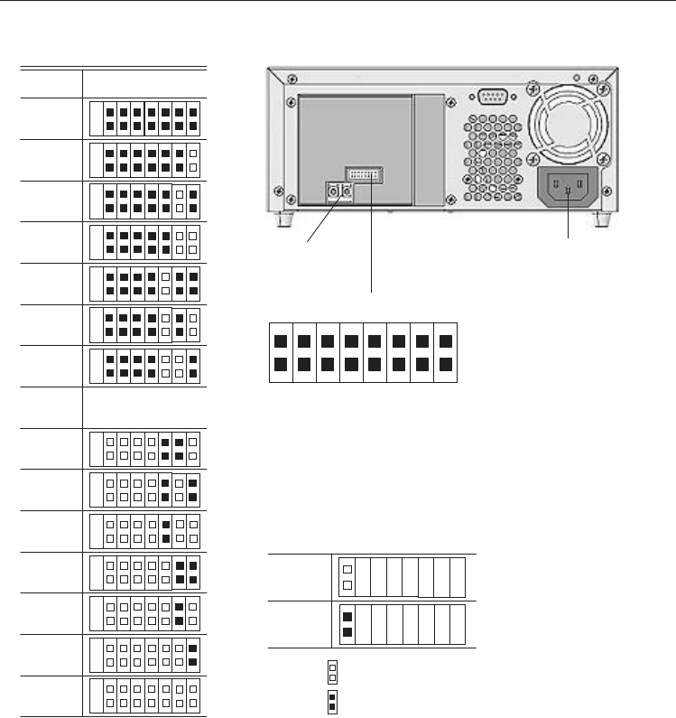
Rear View
➀Connector for maintenance
Not use generally
➁Fan / Air Flow Hole ( for release )
Not be blocked or covered to protect this Library from overheating
➂Fibre Channel Connector
Connect the Fibre Channel interface cable.
Note: In advance, put the SFP Fibre Channel Module (attached) into the drive unit.
➃Jumper
Sets LOOP ID, parity-check, etc.
For details of each jumper setting, refer to 'FC Connection/Setting the LOOP ID'
in next page.
➄Power Connector
Connect the power cord
➀➁
➂➃➄
24 LKM-A121-BC / LKM-A121-BD
Installation
FC Connection/Setting the LOOP ID
Loop ID Jumper
This jumper is functional when the topology is arbitrated loop.
When this jumper is enabled, it gains AL_PA by LIHA (Loop Initialization Hard Assigned).
AL_PA is gained from loop ID. Refer to the table Arbitrated Loop Physical Addresses
(AL_PA) and Loop IDs as the conversion rule.
When this jumper is disabled, requiring AL_PA by LIHA is not executed, and
AL_PA is gained from LISA (Loop Initialization Soft Assigned).
FC Connector
LOOP ID
Note : = CLOSED/Jumper
= OPEN/Jumper not
installed
Jumpers
LOOP ID
LOOP ID
121
122
123
124
125
Reserved
Reserved
2
1
0
3
5
4
6
LOOP ID 0
LOOP ID 1
LOOP ID 2
LOOP ID 3
LOOP ID 4
LOOP ID 5
LOOP ID 6
LOOP ID Enable
...
...
Power Connector
Disable
Enable
0
1
2
3
4
5
6

LKM-A121-BC / LKM-A121-BD 25
Arbitrated Loop Physical Addresses (AL_PA) and Loop IDs
8-bit
AL_PA
(Hex)
EF
E8
E4
E2
E1
E0
DC
DA
D9
D6
D5
D4
D3
D2
D1
CE
CD
CC
CB
CA
C9
C7
C6
C5
C3
BC
BA
B9
B6
B5
B4
B3
B2
B1
AE
AD
AC
AB
AA
A9
A7
A6
A5
8-bit
AL_PA
(Hex)
A3
9F
9E
9D
9B
98
97
90
8F
88
84
82
81
80
7C
7A
79
76
75
74
73
72
71
6E
6D
6C
6B
6A
69
67
66
65
63
5C
5A
59
56
55
54
53
52
51
4E
7-bit Loop ID
(Hex) (Decimal)
00 0
01 1
02 2
03 3
04 4
05 5
06 6
07 7
08 8
09 9
0A 10
0B 11
0C 12
0D 13
0E 14
0F 15
10 16
11 17
12 18
13 19
14 20
15 21
16 22
17 23
18 24
19 25
1A 26
1B 27
1C 28
1D 29
1E 30
1F 31
20 32
21 33
22 34
23 35
24 36
25 37
26 38
27 39
28 40
29 41
2A 42
7-bit Loop ID
(Hex) (Decimal)
2B 43
2C 44
2D 45
2E 46
2F 47
30 48
31 49
32 50
33 51
34 52
35 53
36 54
37 55
38 56
39 57
3A 58
3B 59
3C 60
3D 61
3E 62
3F 63
40 64
41 65
42 66
43 67
44 68
45 69
46 70
47 71
48 72
49 73
4A 74
4B 75
4C 76
4D 77
4E 78
4F 79
50 80
51 81
52 82
53 83
54 84
55 85
8-bit
AL_PA
(Hex)
4D
4C
4B
4A
49
47
46
45
43
3C
3A
39
36
35
34
33
32
31
2E
2D
2C
2B
2A
29
27
26
25
23
1F
1E
1D
1B
18
17
10
0F
08
04
02
01
–
–
–
7-bit Loop ID
(Hex) (Decimal)
56 86
57 87
58 88
59 89
5A 90
5B 91
5C 92
5D 93
5E 94
5F 95
60 96
61 97
62 98
63 99
64 100
65 101
66 102
67 103
68 104
69 105
6A 106
6B 107
6C 108
6D 109
6E 110
6F 111
70 112
71 113
72 114
73 115
74 116
75 117
76 118
77 119
78 120
79 121
7A 122
7B 123
7C 124
7D 125
––
––
––
highest priority
lowest priority
26 LKM-A121-BC / LKM-A121-BD
SWB Setting
SW1 Reserved OFF
SW2 Reserved OFF
SW3 Reserved OFF
SW4 Reserved OFF
SW5 Reserved OFF
SW6 Reserved OFF
SW7 Reserved OFF
SW8 Reserved OFF
12345678
SWB
ON
OFF
SWA Setting
SW1 Reserved OFF
SW2 Reserved OFF
SW3 Reserved OFF
SW4 Reserved OFF
SW5 Reserved OFF
SW6 Reserved OFF
SW7 DC Control-1 ON
SW8 DC Control-2 OFF
12345678
SWA
ON
OFF
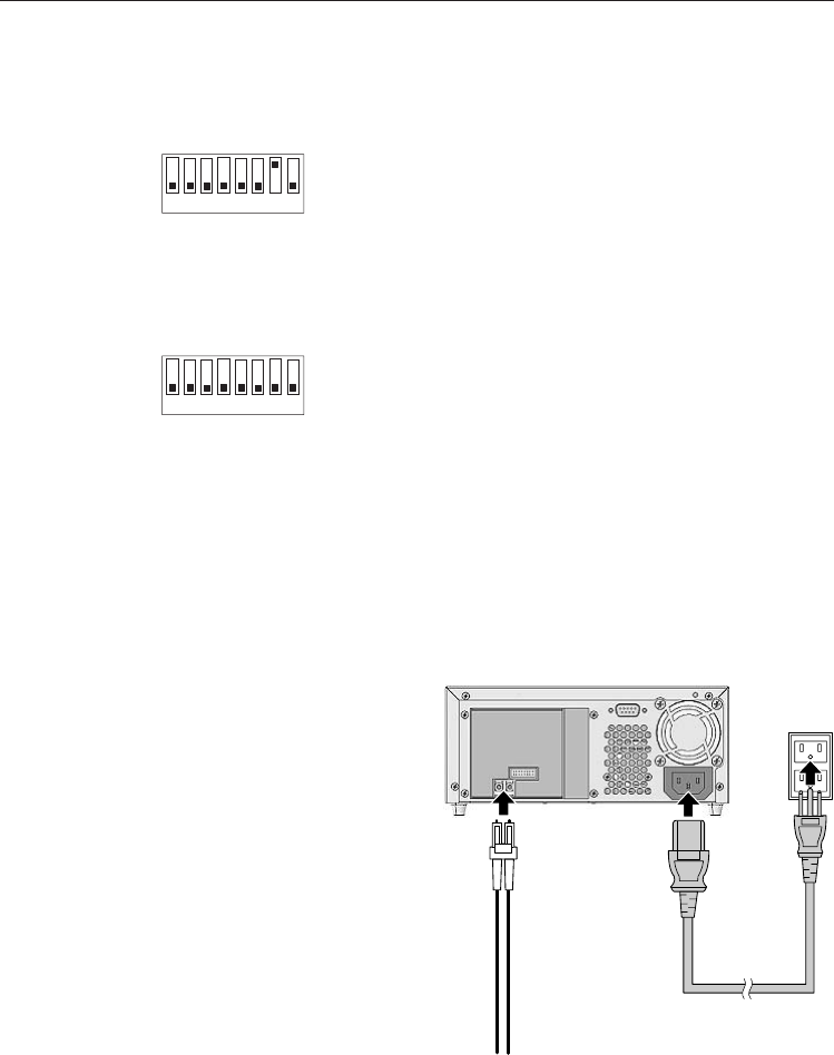
Option Switches ( DIP Switch )
The dip switches locate on the bottom of this drive.
( Not operate these switches generally. )
Power Cord
Fibre Channel interface Cable
Connecting
After make sure that the system (Host PC) power switch is OFF, please connect
the S-AIT drive unit as follows.
1) Connect the Fibre Channel interface
cable to the drive unit.
2) Connect the other end of the Fibre
Channel interface cable to the system
(host PC) Fibre Channel connector.
3) Connect the power cord to the drive unit
and the outlet with earth, and turn the
drive unit power ON.
4) Turn the system (host PC) power ON.
S-AIT Drive Unit (Rear Side)

LKM-A111-BC / LKM-A111-BD / LKM-A121-BC / LKM-A121-BD 27
LED Indication for Drive Status
The LED indicators are defined as follows
GREEN, ALL lit
(0.5 sec.)
then
YELLOW blinks
from left LED to
right LED
repeatedly.
(during Diag for 2
to 3 sec.)
ALL GREEN,
blinking
GREEN, ALL
lit only while
Eject Button
is pressing
UMBER, blinking
UMBER
YELLOW, blinking
YELLOW
GREEN, blinking
GREEN
OFF
Tape Access
in Progress
(Write)
Tape Access
in Progress
(Search)
Tape Loaded
(Write Protected)
Tape Access
in Progress
(Read)
Tape Loaded
(Writable)
No Tape
Drive Error
Occured
Drive Error
Occured
No Drive Error
Occured
Error on Cleaning
Cleaning Request
Cleaning is Not Completed
No Cleaning Request
Occured
LED TAPE MOTION DRIVE ERROR TAPE ERROR CLEANING REQUEST
A Moment of Power ON and Reset
Firmware Update
Eject Inhibit
Media Error
Occured
Media Error
Occured
Media Warning
No Media Error
Occured
Operation ( for Model LKM-A111-BC / LKM-A111-BD / LKM-A121-BC / LKM-A121-BD )
Power LED [GREEN] : lit = Power ON, blinking = FAN is malfunction
28 LKM-A111-BC / LKM-A111-BD / LKM-A121-BC / LKM-A121-BD
Drive Operation
Loading a Cartridge-tape
Insert a cartridge-tape into the cartridge-tape inserting door on the front panel with the
arrow on the cartridge-tape pointing towards the drive. As the Cartridge-tape is inserted,
the drive takes it and automatically loads it into drive mechanism.
Unloading a Cartridge-tape
The cartridge-tape can be removed from the drive unit either in response to a SCSI Unload
Command, or by pressing the eject button.
By pressing Eject button, the drive ejects the cartridge-tape from the cartridge-tape
inserting door.
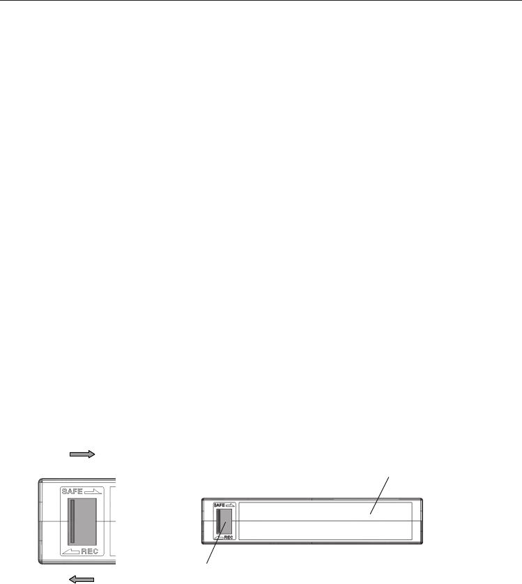
Write-protecting a Cartridge-tape
Cartridge-tapes can be write-protected by sliding the tab on the back of the cartridge-tape.
In this state, data can be read from the tape but not written onto it.
Write-disable
Write-enable
Movable Element of
The Write-inhibit hole
Label area (depth : 0.5)
To avoid condensation onto the cartridge, the Library and cartridge must be kept away from
quick fluctuation (15 deg/ hr) in temperature. If the ambient temperature changes suddenly,
leave around 12 hours in suitable environment before you use it again.
Life extension period of cartridge tape depends on environmental condition, usage and
cleaning cartridge tape. We recommend back up act less than 300 times and to exchange new
cartridge tape as soon as you are aware of failure.
Using a Cleaning Tape
In case of the drive unit, a cleaning function is built in the drive and hence, a periodic
cleaning using cleaning tape such as other format requires is not necessary. However,
when the drive does not recover at the worst case, cleaning tape is recommended to use.
Note : For details of cleaning tape, refer to " System Requirements " in Page 20.
About the Cartridge Tapes

LKM-A111-BC / LKM-A111-BD / LKM-A121-BC / LKM-A121-BD 29
Interface Implementation
( for Model LKM-A111-BC / LKM-A111-BD / LKM-A121-BC / LKM-A121-BD )
Supported SCSI Commands
Erase
Inquiry
Load/Unload
Locate
Log Sense
Log Select
Mode Select
Mode Sense
Prevent Allow Medium Removal
Read
Read Block Limits
Read Buffer
Read Position
Receive Diagnostic Result
Release Unit
Supported SCSI Messages
Abort Message Parity Error
Bus Device Reset Message Reject
Command Complete No Operation
Disconnect Restore Pointers
Extended Message Save Data Pointer
- Synchronous Data Transfer Request
- Wide Data Transfer Request
Identify ( w/&w/o Disconnect )
Ignore Wide Residue
Report Density Support
Report Luns
Request Block Address
Request Sense
Reserve Unit
Rewind
Seek Block
Send Diagnostic
Space
Test Unit Ready
Verify
Write
Write Buffer
Write Filemarks

30 LKM-A111-BC / LKM-A111-BD / LKM-A121-BC / LKM-A121-BD
Maintenance
( for Model LKM-A111-BC / LKM-A111-BD / LKM-A121-BC / LKM-A121-BD )
We recommend to maintain periodically the drive and the cartridge-tape to use safely
and comfortably.
When maintaining, please take care the below contents.
■Keep the cartridge-tape away from direct sunlight, high temperature, and high
humidity place.
If it is not, it may result in the data destroy.
■Do not touch on the tape surface.
If touch it, it may result in the data destroy.
If touch it to soil, it may be impossible to write/read data normally.
■Do not clean with chemical or cleanser.
If use chemical or cleanser (static guard, etc.), it may result in the data destroy
or a malfunction.
■Do not paste paper or label, etc.
If paste, it may result in the data destroy or a malfunction.
■Do not drop or bend the cartridge-tape, or do not take out the tape in the cartridge.
If the tape crack or transform, it may be impossible to write/read data normally.
■When the drive dirt is cruel.
Do not clean the drive with benzine or thinner, etc.
If do it, it may result in change in the plastic quality or the paint coming off
on the drive cabinet.
When use the chemical duster, follow the notice writing of it.
Please clean the dirt with soft cloth dipped by water or kitchen-cleanser(synthetic)
and squeezed firmly.
LKM-A111-BC / LKM-A111-BD / LKM-A121-BC / LKM-A121-BD 31
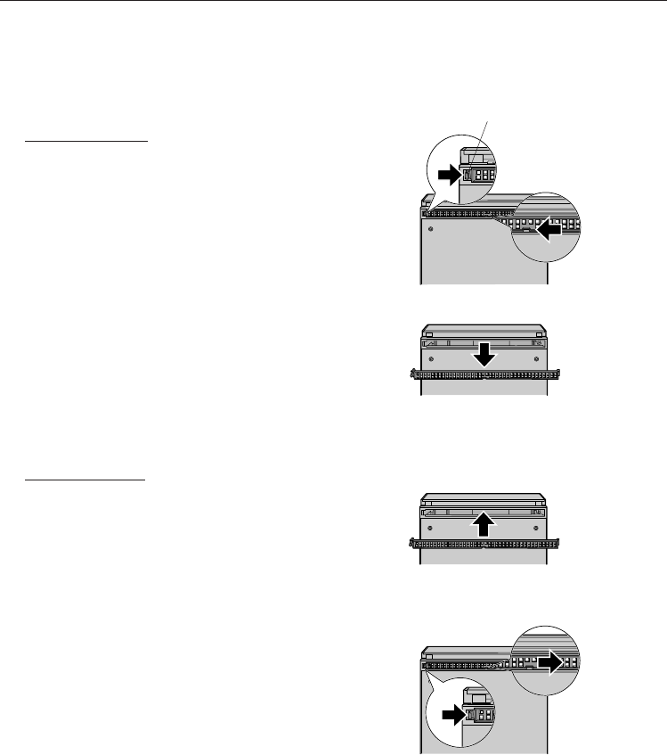
Filter Exchanging
The Filter is attached on the Air Flow Hole in bottom of the drive unit.
We recommend to exchange the Filter about one time in a year as following steps.
Filter Removing
1) Push the tub in left end of the Filter
attached to the Air Flow Hole to unlock.
2) Slide the Filter to left(arrow) direction to
unlock the Center Lock.
3) Remove the Filter from the drive unit.
When the Center Lock is unlocked, the
Right End Lock is unlocked at the same
time, and then the all Filter is removed.
Filter Attaching
1) Prepare a new Filter.
2) Slide the Filter to right(arrow) direction
with sheet side pointing to the drive unit
to lock the Center Lock.
Lock also the right end of the Filter
locking the center portion.
3) Push the tub in left end of the Filter to
right(arrow) direction to attached the
Filter to the drive unit.
Lock securely by the tub in left end of
the Filter.
Bottom Side
Bottom Side
Tub

32 LKM-A111-BC / LKM-A111-BD / LKM-A121-BC / LKM-A121-BD
Specification
( for Model LKM-A111-BC / LKM-A111-BD / LKM-A121-BC / LKM-A121-BD )
Cartridge Tape Performance
Environmental Conditions
General Performance
Data Capacity (S-AIT1 / 600 m) *1 500 GByte ( compression mode : 1300 GByte )
Transfer Rate (S-AIT1) *2 30 MByte/s ( compression mode : 78 GByte/s )
Note :
*1 ) Compression Rate = 2.6 x ( Compression Rate is changed with data type.)
*2 ) Transfer Rate may be different with system(host PC) performance.
Search Time (average) 70 s
Interface Ultra 160 Wide LVD/SE SCSI (LKM-A111-B)
2 GByte/s Fiber-Channel (LKM-A121-B)
Buffer Memory 72 MByte
Error Rates Less than 10 –17
Power Rating 100 – 240 V ~ AUTO
0.7 – 0.4 A 50 / 60 Hz
Dimensions (W x H x D) 210 x 86 x 370 mm
Weight 6.7 kg [ typical ]
Operating Non-operating
• Temperature 5 ~ 35 °C – 40 ~ 70 °C
(No cartridge-tape)
• Humidity 20 ~ 80 %Rh 5 ~ 95 %Rh
(Non-condensation) (Non-condensation)
Installation : Horizontal
LKM-A111-BC / LKM-A111-BD / LKM-A121-BC / LKM-A121-BD 33
Appendix ( for Model LKM-A111-BC / LKM-A111-BD / LKM-A121-BC / LKM-A121-BD )
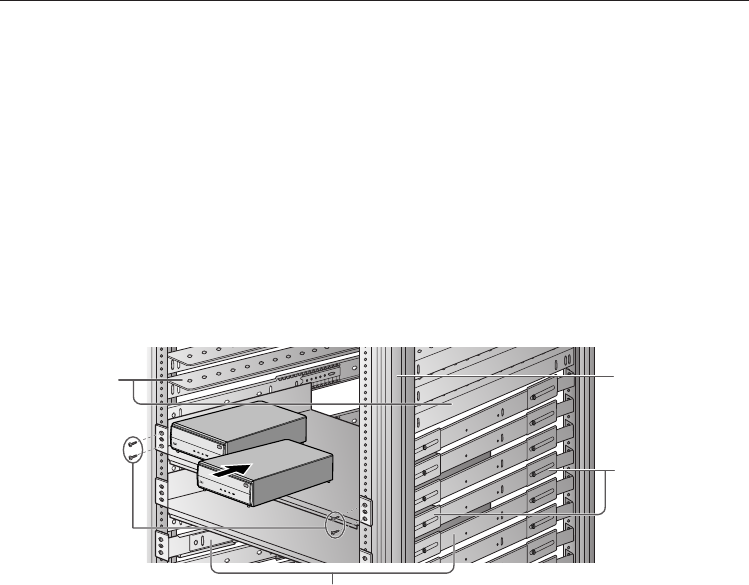
Mounting the Drive Unit to Rack
1) If you need the Rail (Rail-Bracket) or Angle for mounting to your rack, attach the suitable
ones for the Rack / Drive unit to them.
– For details of installing the Rail (Rail-Bracket) or Angle, refer to each manual for them.
2) Gently slide the Drive unit into the vacant rack part, and secure it with the mounting screws
as below figure.
Angle
Rail
Rail-Bracket
Note :
Surely mount to horizontal direction.
The above equipments ( Angle/ Rail/ Rail-Bracket/ Screw ) are NOT included
with this product.
Rack
Mounting
Screw
Rack
34 LKM-A111-BC / LKM-A111-BD / LKM-A121-BC / LKM-A121-BD
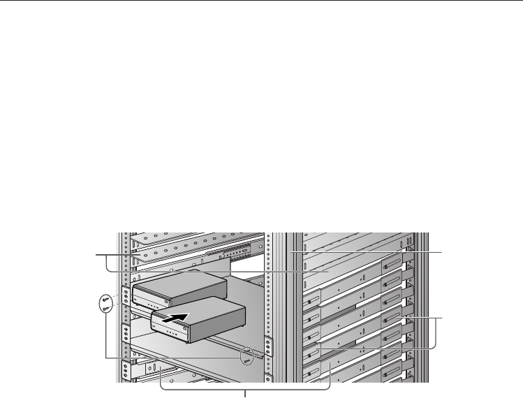
1) Wenn Sie für die Montage in Ihr Rack die Schiene (Schienenträger) oder den Winkel
benötigen, befestigen Sie bitte das für das Rack / die Antriebseinheit passende Teil.
– Einzelheiten zur Installation der Schiene oder des Winkels finden Sie im entsprechenden
Handbuch.
2) Schieben Sie die Antriebseinheit behutsam in den freien Rackteil und sichern Sie sie - wie
in der nachfolgenden Abbildung gezeigt - mit den Montageschrauben.
Hinweis:
Führen Sie die Montage sicher in horizontaler Richtung durch.
Die oben aufgeführten Ausrüstungen (Winkel / Schiene / Schienenträger / Schraube) sind
NICHT im Lieferumfang dieses Produktes enthalten.
Rack
Winkel
Schienenträger
Schiene
Rack-
Montageschraube
– German –
Anhang ( für den Typ LKM-A111-BC / LKM-A111-BD / LKM-A121-BC / LKM-A121-BD )
Montage

35
Memo
Specifications are subject to change without notice.
LMQT00623 Printed in Japan
Rev. A