Panasonic Mobile Communications 611849144431A RRH4x40-PCS KS24829L11 User Manual
Panasonic Mobile Communications Co., Ltd. RRH4x40-PCS KS24829L11
User Manual

PCS RRH List11 Installation Guide Issue: 1.0.0
1/17 PMC CONFIDENTIAL
PCS RRH List11
Installation Guide
Product Name : RRH4x40-PCS KS24829L11
Model Number : 849144431
Issue: 1.0.0
Date; July 21, 2011

PCS RRH List11 Installation Guide Issue: 1.0.0
2/17 PMC CONFIDENTIAL
Revison History
Issue No. Description Date
1.0.0 First edition July 08, 2011

PCS RRH List11 Installation Guide Issue: 1.0.0
3/17 PMC CONFIDENTIAL
Table of Contents
Revison History ..................................................................................................................................... 2
Table of Contents ................................................................................................................................... 3
1 INTRODUCTION ............................................................................................................................. 4
1.1 System Overview ...................................................................................................................... 4
1.2 Equipment Outline .................................................................................................................... 5
1.3 Structural Outline ...................................................................................................................... 6
1.4 Specification ............................................................................................................................. 7
1.4.1 System Specification .......................................................................................................... 7
1.4.2 Optical Module Specification .............................................................................................. 8
1.4.3 PCS Band Remote Radio Heads Specification ................................................................... 9
2 Installing the RRH ......................................................................................................................... 10
2.1 Appearance ............................................................................................................................ 10
2.2 User Interface ......................................................................................................................... 11
2.3 Cable List ............................................................................................................................... 13
2.4 Power cable installing procedure ............................................................................................ 14
2.5 Powering On the RRH ............................................................................................................ 16
2.6 System Start-Up Procedure .................................................................................................... 16
3 FCC WARING ............................................................................................................................... 17
PCS RRH List11 Installation Guide Issue: 1.0.0
4/17 PMC CONFIDENTIAL
1 IN TRODUCTION
1.1 S ystem Overview
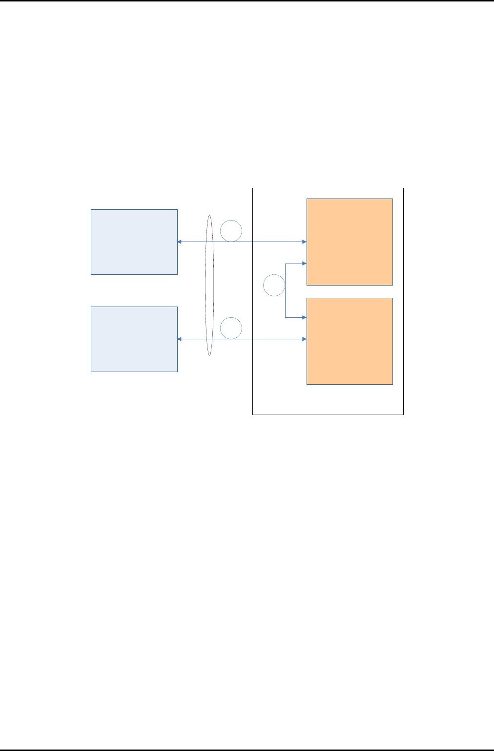
PCS R RH List11 co nnect w ith BBU w hich made by Alcatel -Lucent. An d, this RR H is transiver
system which is support LTE and CDMA fuction in 1900MHz frequency band range.
List11 consist from 2pcs of List10 whch is connected by optical cabel.
CPRI Interface of one PCS RRH List10 connect to BBU (LTE)
Another one CPRI interface connect to BBU (CDMA)
BBU(LTE)
BBU(CDMA)
PCS RRH
TX25MHz
List10
PCS RRH
TX25MHz
List10
CPRI
PCS RRH List11
Figure 1-1 System Overview
PCS RRH List11 Installation Guide Issue: 1.0.0
5/17 PMC CONFIDENTIAL
1.2 Equipment Outline
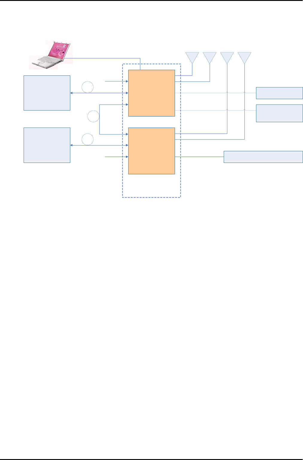
Figure 1-2 Equipment Outline
① Execute transmit and receive BBU and UL/DL Digital Signal by optical interface
② Enable to maintain RRH with O CI (On site Confi guration Inte rface) an d Pe rsonal
Computer.
③ Enable to use Alarm-interface detect function(one is moni toring. another is detection
for 2pcs List10)
④ AISG suppl y an d contr ol po wer function w hich is connec ted to towe r-top e quipment
from
RRH
⑤ This system support DC -48 Vpower input
⑥ Execute sever al fun ctions (S tatus-Control/Tranciver-Control/Mesurement/Failure
-Control…) based on control message of BBU.
⑦ Enable to download Software(Control Software, DSP Firmware、FPGA Data) as
Remotely.
BBU (LTE)
BBU (CDMA) PCS RRH
TX25MHz
List10
PCS RRH
TX25MHz
List10
CPRI
CPRI
CPRI
Tower-top
Equipment
AISG
DC - 48V
OCI
( Ether)
Alams Monitor
Alams
Identification connector
DC - 48V
Primary
Primary
Secondary
Secondary
PCS RRH List11

PCS RRH List11 Installation Guide Issue: 1.0.0
6/17 PMC CONFIDENTIAL
1.3 S tructural Outline
【Structure Outline】
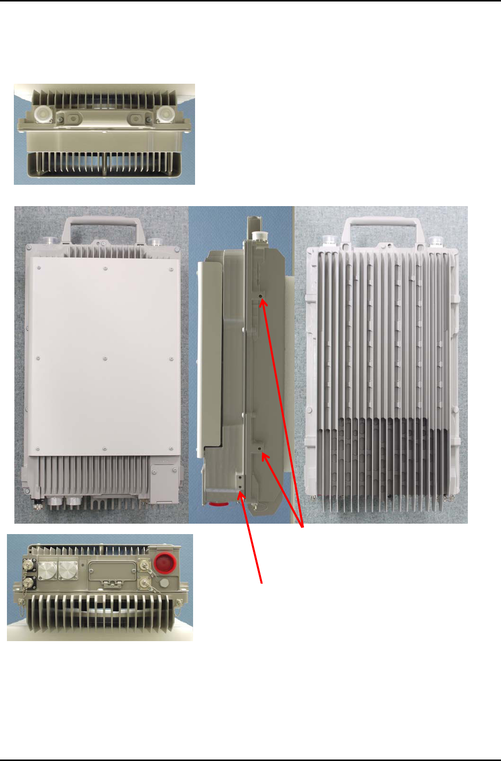
① 1system(List11) consist from 2pcs of RRH(List10)
② Thermal method is naturally air‐cooled engine(Cooling Fan Less)
③ Enable to l oad next ca ble (P ower Cable/Optical C able/AISG Ca ble/ALM Ca ble/AUX
Cable) from bottom side of the RRH. And, enable to load Antenna Cable from Upper
side of the system
④ Equipped M6 electrical ground in lower side of the system
⑤ In order to monitoring output power of transmi ssion point, Implement 2pcs (List10) of
electrical terminal.
⑥ There are installing “Water proof cap” and “Dust Proof Cap” as external connector
⑦ There are LED in bottom side of the RRH which can monitoring system status.
⑧ All function can control by control box which box can be open
⑨ Enable to install “ibolt” to upper side of the system

PCS RRH List11 Installation Guide Issue: 1.0.0
7/17 PMC CONFIDENTIAL
1.4 S pecification
1.4.1 S ystem Specification
No Item Content Remark
1 Input Power -48V (-37V~-57V)
2 Powe r Consumption 340.7W x2
3 W eight Less than 20kg
4 Water resistant level IP65 as specified by IEC529
IP66 as specified by IEC60529
NEMA type4
5 T emperature range -40~+55℃
6 Humi dity range 5~95%
7 Dime nsion W:330 mm
D:176 mm
H:530 mm
( not include connectors )
8 Thermal Type naturally air cooled engine
9 Setting Location Outside

PCS RRH List11 Installation Guide Issue: 1.0.0
8/17 PMC CONFIDENTIAL
1.4.2 Optical Module Specification
No Item Condition/etc Remark
1 Optical Center
Length
<Primary port>
DL:1550 nm、UL:1310 nm
<Secondary port>
Mix mode:1550 nm/1310 nm
RRH1:1550 nm, RRH2:1310 nm
or
RRHq:1310 nm, RRH2:1550 nm
2 Bit Rate
<Primary port>
CDMA:0.6144 Gbps~1.2288 Gbps
LTE :1.2288 Gbps~6.1440 Gbps
<Secondary port>
2.4576 Gbps~6.144 Gbps
3 Transmission
Distance
<Primary port>
Maximum 20 km
<Secondary port>
Maximum 50m

PCS RRH List11 Installation Guide Issue: 1.0.0
9/17 PMC CONFIDENTIAL
1.4.3 PCS Band Remote Radio Heads Specification
No Item Type Remark
1 Supp ort Technologies LTE/CDMA
2 RF Output Power 40W/Branch×2×2 List11 co nsist fr om 2pcs of
List10
3 Downlink RF Frequency 1930 MHz –1995 MHz
4 Uplink RF Frequency 1850 MHz –1915 MHz
5 Numb er of Carrier LTE :2Carrier×2
CDMA:8Carrier×2
List11 co nsist fr om 2pcs of
List10
PCS RRH List11 Installation Guide Issue: 1.0.0
10/17 PMC CONFIDENTIAL
2 Installing the RRH
2.1 Appe arance
Figure 2-1 Appearance of the RRH with connector covers
(There are 2-M8 female threads on opposite side)
4-M8 female threads for Equipment mounting
4-M6 female threads for Ground Lugs
(There are 2-M6 female threads on opposite
id )
PCS RRH List11 Installation Guide Issue: 1.0.0
11/17 PMC CONFIDENTIAL
2.2 U ser Interface
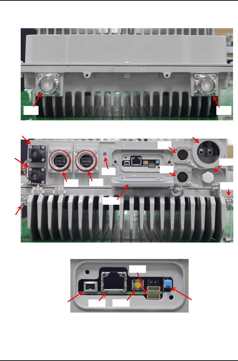
Figure 2-2 User Interface (Top view)
Figure 2-3 User interface (Bottom view)
Figure 2-4 Detail of Service Access Ports
(1) (2)
(8)
(3)
(4)
(5) (6)
(7)
(10)
(11)
(12)
(13)
(9)
(14)
(15) (16) (17) (19)
(18)

PCS RRH List11 Installation Guide Issue: 1.0.0
12/17 PMC CONFIDENTIAL
Table 2-1 Connectors, LED, Reset button etc.
No. Location Connector Name Connector Type and Comment
1 On the Top TX/RX 1 7/16 DIN F
2 TX/RX 2 7/16 DIN F
3 On the Bottom AUX RX1 N-type F
4 AUX RX2 N-type F
5 CPRI PRI SFP Connector Tyco Electronics 1888247-1
SFP Shield Cage Tyco Electronics 2007198-1
Flange Connector SFP with Waterproof Radial
Part# R299.988.00
6 CPRI SEC SFP Connector Tyco Electronics 1888247-1
SFP Shield Cage Tyco Electronics 2007198-1
Flange Connector SFP with Waterproof Radial
Part# R299.988.00
7 Status LED Indicate green or red or yellow
8 AISG Female 8-pin circular connector, per IEC 60130-9
9 External User
Alarms 1-4
Female 8-pin circular connector, per IEC 60130-9
10 DC -48V IN Water-proof entry connector can be mounted
11 V entilator
12 TX MON 1 SMA F
13 TX MON 2 SMA F
14 Service access door
15 Service access Port
on the Bo ttom of the
RRH
Serial Interface IEEE1394
16 OCI (Ethernet) RJ45
17 Reset button -
18 Domestic Port 1
19 Sensor for service access door

PCS RRH List11 Installation Guide Issue: 1.0.0
13/17 PMC CONFIDENTIAL
2.3 Cable List
1. Power cable; # 14 AWG strand wires are recommended.
From # 14 to # 8 AWG strand wires are available.
PCS RRH List11 Installation Guide Issue: 1.0.0
14/17 PMC CONFIDENTIAL
2.4 Power cable installing procedure
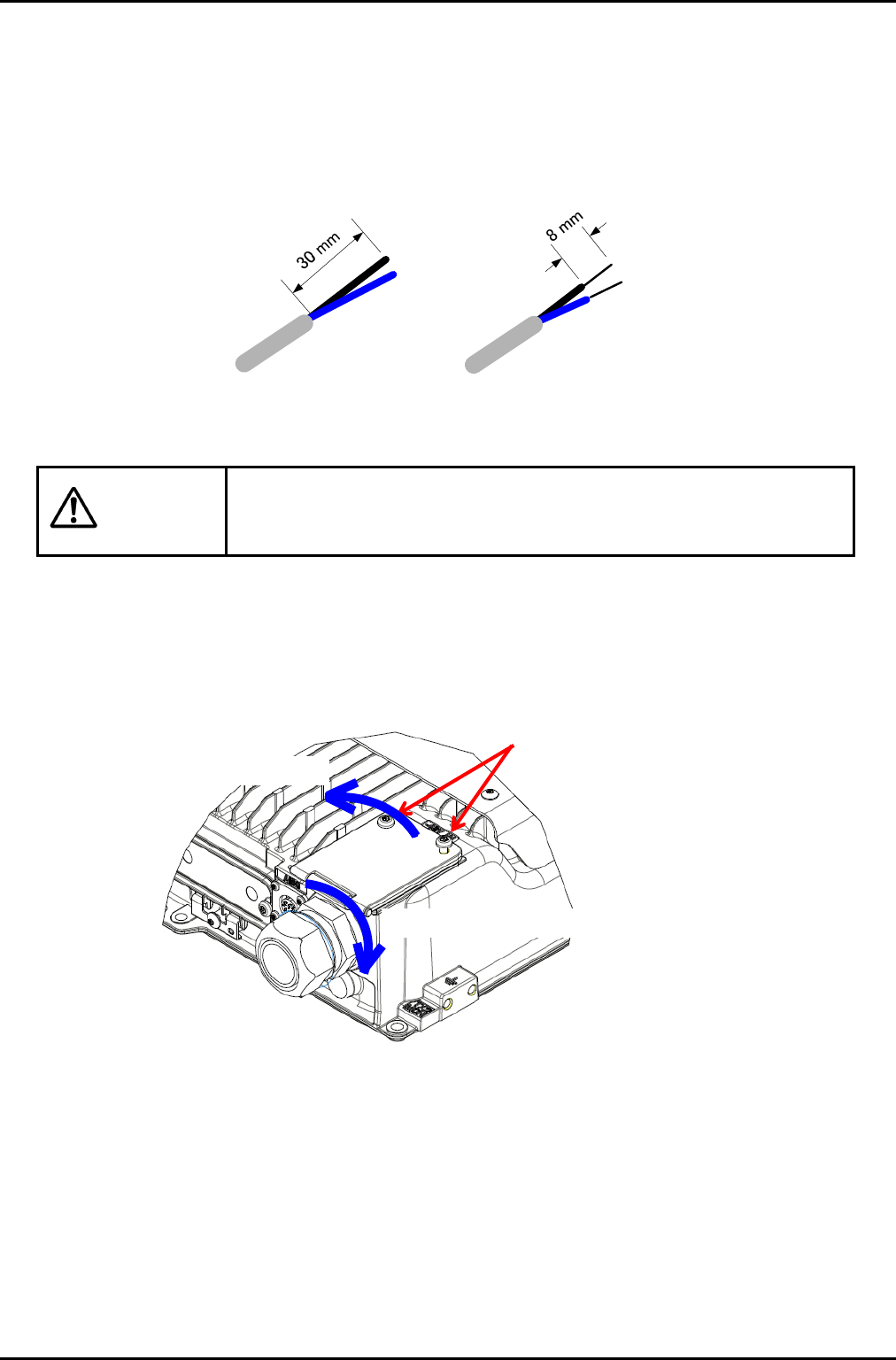
1. Preparation of Power cable
1.1. Remove the jacket of power cable by 30 mm.
1.2. Strip the jacket from an inner cable by 8 mm.
Figure 2-5 Preparation of Power cable
Do not damage the power cable when cutting around jacket.
2. Loose the screws of cabling cavities cover.
3. Open the cover
4. Mount entry connector (water-proof type) on the DC-48V-IN port.
Figure 2-6 Preparation of the equipment
Screws of cabling cavity
Open the cover
Mount entry connector on the DC-48V-IN port
Warning
PCS RRH List11 Installation Guide Issue: 1.0.0
15/17 PMC CONFIDENTIAL
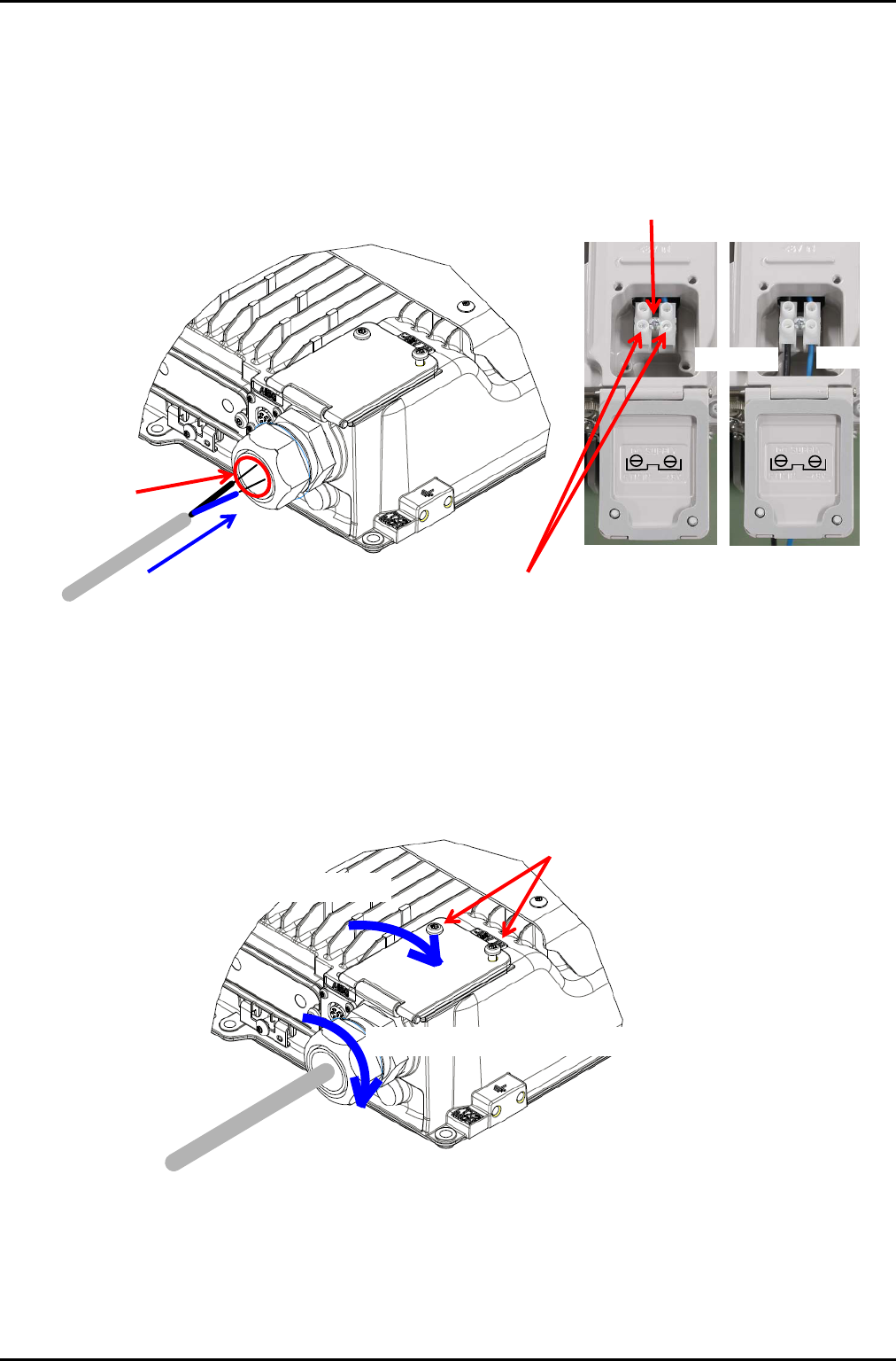
5. Put power cable inside from the hole of entry connector
6. Loose cable fixing screws of terminal block
7. Insert each cable to th e suitable hole of terminal, according to the instruction of the rear of the
cover
8. Fix the terminal screws 10 in-lbs (1.13 Nm)
Figure 2-7 Fixing Power cables
9. Fix the cable by entry connector
10. Close the cabling cavities cover
11. Fix the screws of cabling cavity’s cover xx Nm
Figure 2-8 Fixing Power cable and cover
Fix Power cable by entry connector
Close the cover
Cable fixing screws
Put Power cable inside
The hole of entry
connecter
Cable fixing screws
Terminal block
-48RTN.I
DC SUPPLY
-48RTN.I
DC SUPPLY
-48V
RTN IN

PCS RRH List11 Installation Guide Issue: 1.0.0
16/17 PMC CONFIDENTIAL
2.5 Powering On the RRH
1. Turn off the breaker of the power supply and connect the power supply cable.
2. Connect the other cables before turn on the breaker.
3. After start up the BBU, please turn on the power supply to RRH.
4. Please confirm the RRH start state with Status LED.
2.6 S tatus LED
LED Display States
No. S tate LED Display
1 No Power Supplied Off
2 Initial Power Supply Solid Red
3 External Power Supply
Failure
Flash Red
4 Sof tware Download Flash Yellow
5 No nrecoverable Critical
Failure
Solid Red
6 Reco verable Critical
Failure
Flasu Red
7 Slave CPRI Ling Failure Solid Yellow
8 No n-Critical
Nonrecoverable Failure
Solid Red
9 No n-Critical
Recoverable Failure
Flash Red
10 External Antenna Failure Flash Red
11 Normal Operation Solid Green
12 S tandby Flash Green

PCS RRH List11 Installation Guide Issue: 1.0.0
17/17 PMC CONFIDENTIAL
3 FCC WARING
Changes or modifications not expressly approved by the party responsible for compliance
could void the user’s authority to operate the equipment.
Properly shielded an d grounded cabl es and conn ectors must b e used for connection to
host computers and / or peripherals in order to meet FCC emission limits.
Data transmission is always initiated by software, which is th e passed down through the
MAC, through the digital and analog baseband, and finally to the RF chip. Several special
packets are initiated by the MAC. These are the only ways the digital baseband portion will
turn on the RF transmitter, which it then turns off at the end of the packet. Therefore, the
transmitter will be on only while one of the aforementioned packets is being transmitted. In
other words, this device automatically discontinue transmission in case of either absence
of information to transmit or operational failure.
Frequecncy Tolerance: 11 ppb
This transmitter must not be co-located or operated in conjunction with any other antenna
or transmitter.