Panasonic of North America 11AR1201 ACTIVE SUBWOOFER User Manual SB HWA550 Part 1
Panasonic Corporation of North America ACTIVE SUBWOOFER SB HWA550 Part 1
Contents
User Manual_SB-HWA550_(Part 1)
until
2012/04/30
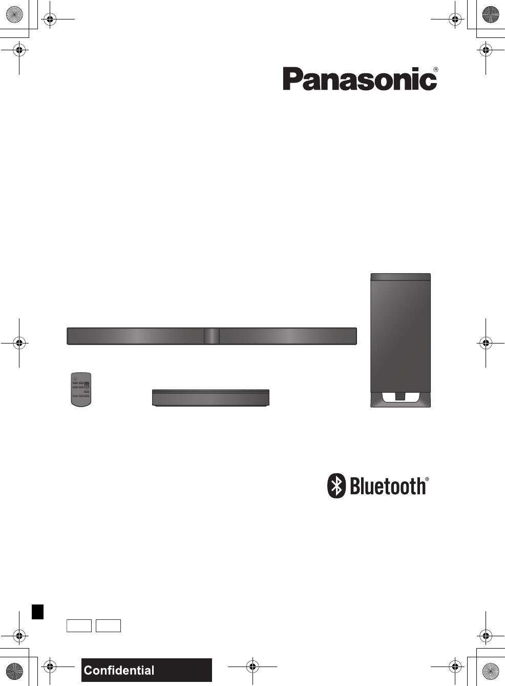
Owner’s Manual
Home Theater Audio System
Model No. SC-HTB550
P
Thank you for purchasing this product.
For optimum performance and safety, please read these instructions carefully.
Please keep this manual for future reference.
If you have any questions, contact:
U.S.A. and Puerto Rico: 1-800-211-PANA (7262)
Canada: 1-800-561-5505
RQT9660-P
PC
SC-HTB550_RQT9660_mst.book Page 1 Tuesday, December 20, 2011 1:55 PM
2RQT9660
IMPORTANT SAFETY INSTRUCTIONS
Read these operating instructions carefully before using the unit. Follow the safety instructions on the
unit and the applicable safety instructions listed below. Keep these operating instructions handy for
future reference.
1 Read these instructions.
2 Keep these instructions.
3 Heed all warnings.
4 Follow all instructions.
5 Do not use this apparatus near water.
6 Clean only with dry cloth.
7 Do not block any ventilation openings. Install in
accordance with the manufacturer’s instructions.
8 Do not install near any heat sources such as radiators,
heat registers, stoves, or other apparatus (including
amplifiers) that produce heat.
9 Do not defeat the safety purpose of the polarized or
grounding-type plug. A polarized plug has two blades with
one wider than the other.
A grounding-type plug has two blades and a third
grounding prong. The wide blade or the third prong are
provided for your safety. If the provided plug does not fit
into your outlet, consult an electrician for replacement of
the obsolete outlet.
10 Protect the power cord from being walked on or pinched
particularly at plugs, convenience receptacles, and the
point where they exit from the apparatus.
11 Only use attachments/accessories specified by the
manufacturer.
12 Use only with the cart, stand, tripod,
bracket, or table specified by the
manufacturer, or sold with the apparatus.
When a cart is used, use caution when
moving the cart/apparatus combination
to avoid injury from tip-over.
13 Unplug this apparatus during lightning
storms or when unused for long periods of time.
14 Refer all servicing to qualified service personnel.
Servicing is required when the apparatus has been
damaged in any way, such as power-supply cord or plug
is damaged, liquid has been spilled or objects have fallen
into the apparatus, the apparatus has been exposed to
rain or moisture, does not operate normally, or has been
dropped.
Unit
≥To reduce the risk of fire, electric shock or product damage,
jDo not expose this unit to rain, moisture, dripping or
splashing.
jDo not place objects filled with liquids, such as vases, on
this unit.
jUse only the recommended accessories.
jDo not remove covers.
jDo not repair this unit by yourself. Refer servicing to
qualified service personnel.
Button-type battery (Lithium battery)
≥Risk of fire, explosion and burns. Do not disassemble, heat
above 60 oC (140 oF) or incinerate.
Unit
≥Do not place sources of naked flames, such as lighted
candles, on this unit.
Placement
≥To reduce the risk of fire, electric shock or product damage,
jDo not install or place this unit in a bookcase, built-in
cabinet or in another confined space. Ensure this unit is
well ventilated.
jDo not obstruct this unit’s ventilation openings with
newspapers, tablecloths, curtains, and similar items.
Button-type battery (Lithium battery)
≥Danger of explosion if battery is incorrectly replaced.
Replace only with the type recommended by the
manufacturer.
≥When disposing the batteries, please contact your local
authorities or dealer and ask for the correct method of
disposal.
≥Insert with poles aligned.
≥Do not touch the terminals (i and j) with metal objects.
≥Do not recharge, disassemble, remodel, heat or throw into
fire.
≥Keep out of reach of children.
≥Mishandling of batteries can cause electrolyte leakage and
may cause a fire.
jRemove the battery if you do not intend to use the remote
control for a long period of time. Store in a cool, dark
place.
≥Do not heat or expose to flame.
≥Do not leave the battery(ies) in a car exposed to direct
sunlight for a long period of time with doors and windows
closed.
WARNING
If any electrolyte should come into contact with your hands
or clothes, wash it off thoroughly with water.
If any electrolyte should come into contact with your eyes,
never rub the eyes. Rinse eyes thoroughly with water, and
then consult a doctor.
<For USA-California only>
This product contains a CR Coin Cell Lithium
Battery which contains Perchlorate Material s
special handling may apply.
See www.dtsc.ca.gov/hazardouswaste/perchlorate.
CAUTION
SC-HTB550_RQT9660_mst.book Page 2 Tuesday, December 20, 2011 1:55 PM
RQT9660 3
Precautions
THE FOLLOWING APPLIES ONLY IN THE
U.S.A. AND CANADA
This device complies with Part 15 of FCC Rules and RSS-
Gen of IC Rules.
Operation is subject to the following two conditions:
(1) This device may not cause interference, and (2) this
device must accept any interference, including
interference that may cause undesired operation of this
device.
This transmitter must not be co-located or operated in
conjunction with any other antenna or transmitter.
This product is restricted to indoor use due to its operation
in the 5.150 GHz to 5.250 GHz and 5.725 GHz to
5.850 GHz frequency range.
FCC and IC require this product to be used indoors for the
frequency range 5.150 GHz to 5.250 GHz and 5.725 GHz
to 5.850 GHz to reduce the potential for harmful
interference to co-channel Mobile Satellite systems. High
power radars are allocated as primary users of the
5.25 GHz to 5.35 GHz and 5.65 GHz to 5.85 GHz bands.
These radar stations can cause interference with and/or
damage this product.
This equipment complies with FCC/IC radiation exposure
limits set forth for an uncontrolled environment and meets
the FCC radio frequency (RF) Exposure Guidelines in
Supplement C to OET65 and RSS-102 of the IC radio
frequency (RF) Exposure rules. This equipment has very
low levels of RF energy that is deemed to comply without
maximum permissive exposure evaluation (MPE). But it is
desirable that it should be installed and operated keeping
the radiator at least 20 cm (7 7/
8q) or more away from
person’s body (excluding extremities: hands, wrists, feet
and ankles).
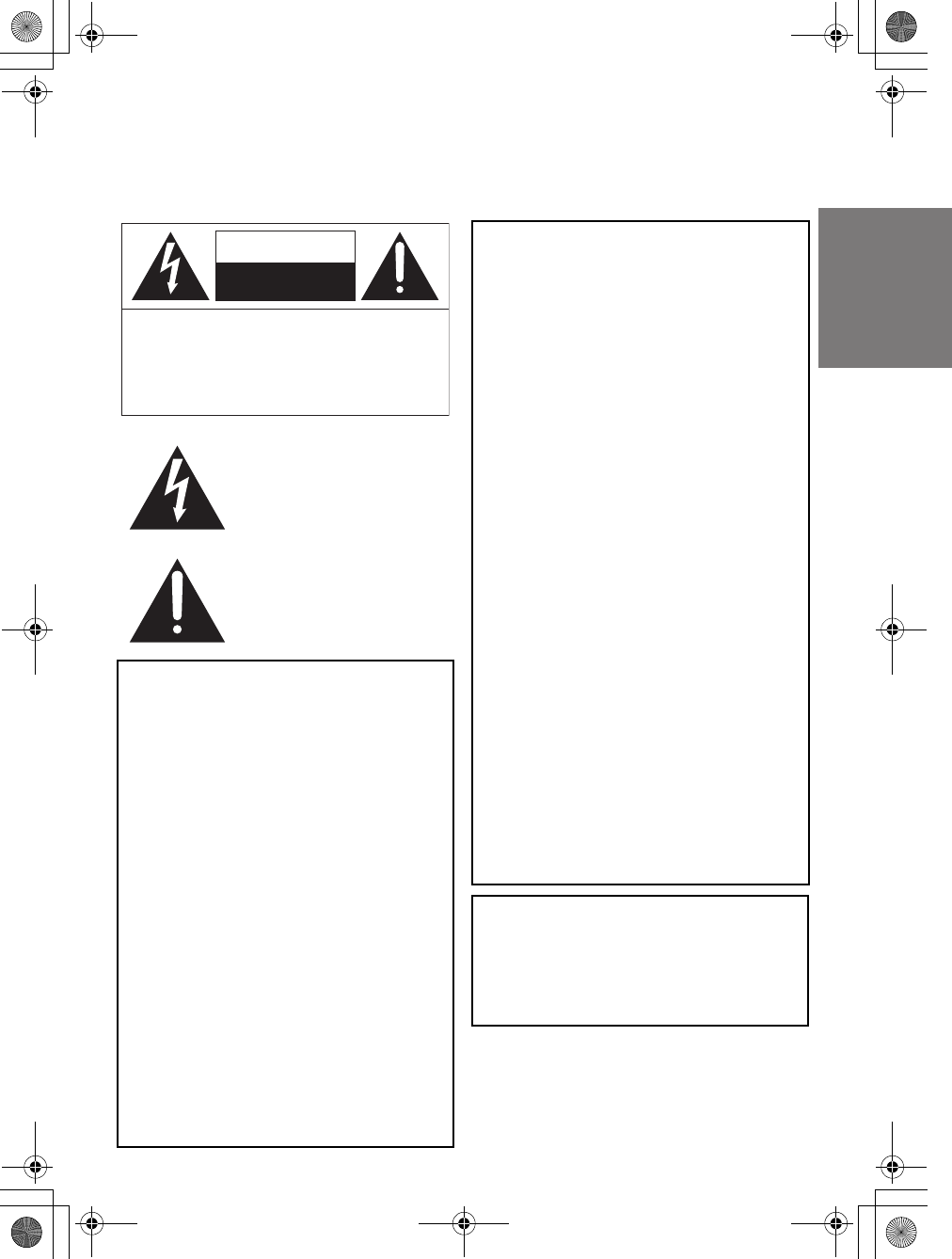
The lightning flash with arrowhead
symbol, within an equilateral triangle,
is intended to alert the user to the
presence of uninsulated “dangerous
voltage” within the product’s
enclosure that may be of sufficient
magnitude to constitute a risk of
electric shock to persons.
The exclamation point within an
equilateral triangle is intended to alert
the user to the presence of important
operating and maintenance
(servicing) instructions in the literature
accompanying the appliance.
CAUTION: TO REDUCE THE RISK OF ELECTRIC
SHOCK, DO NOT REMOVE SCREWS.
NO USER-SERVICEABLE PARTS
INSIDE.
REFER SERVICING TO QUALIFIED
SERVICE PERSONNEL.
CAUTION
RISK OF ELECTRIC SHOCK
DO NOT OPEN
THE FOLLOWING APPLIES ONLY IN THE
U.S.A.
FCC Note:
This equipment has been tested and found to comply with
the limits for a Class B digital device, pursuant to Part 15
of the FCC Rules.
These limits are designed to provide reasonable protection
against harmful interference in a residential installation.
This equipment generates, uses and can radiate radio
frequency energy and, if not installed and used in
accordance with the instructions, may cause harmful
interference to radio communications.
However, there is no guarantee that interference will not
occur in a particular installation. If this equipment does
cause harmful interference to radio or television reception,
which can be determined by turning the equipment off and
on, the user is encouraged to try to correct the interference
by one or more of the following measures:
≥Reorient or relocate the receiving antenna.
≥Increase the separation between the equipment and
receiver.
≥Connect the equipment into an outlet on a circuit
different from that to which the receiver is connected.
≥Consult the dealer or an experienced radio/TV
technician for help.
Any unauthorized changes or modifications to this
equipment would void the user’s authority to operate this
device.
This device complies with Part 15 of the FCC Rules.
Operation is subject to the following two conditions:
(1) This device may not cause harmful interference, and
(2) this device must accept any interference received,
including interference that may cause undesired
operation.
Responsible Party:
Panasonic Corporation of North America
One Panasonic Way,
Secaucus, NJ 07094
Support Contact:
Panasonic Consumer Marketing Company of
North America
Telephone No.: 1-800-211-PANA (7262)
THE FOLLOWING APPLIES ONLY IN
CANADA.
This device complies with RSS-210 of the IC Rules.
Operation is subject to the following two conditions:
(1) This device may not cause harmful interference,
(2) This device must accept any interference received,
including interference that may cause undesired operation
of the device.
SC-HTB550_RQT9660_mst.book Page 3 Tuesday, December 20, 2011 1:55 PM
4RQT9660
Table of contents
IMPORTANT SAFETY INSTRUCTIONS ............................................................ 2
Before use
Supplied items ................................................................................................... 5
System (SC-HTB550) ......................................................................................................... 5
Accessories......................................................................................................................... 5
Control reference guide .................................................................................... 6
Main unit and active subwoofer (Front)............................................................................... 6
Main unit and active subwoofer (Rear) ............................................................................... 6
Remote control.................................................................................................................... 7
Getting started
Step 1 Selecting the placement method......................................................... 8
Speaker system .................................................................................................................. 9
Active subwoofer................................................................................................................. 9
Wireless interference .......................................................................................................... 9
Step 2 Assembling the speakers................................................................... 10
When attaching the speakers to a wall ............................................................................. 10
When placing the speakers on a table.............................................................................. 14
Additional speaker fall prevention measures .................................................................... 17
Step 3 Connections ........................................................................................ 19
Connection with the TV..................................................................................................... 19
Connection with other devices .......................................................................................... 20
Speaker cable connection................................................................................................. 21
AC power supply cord connection .................................................................................... 21
Active subwoofer wireless connection .............................................................................. 22
Bluetooth® connection ....................................................................................................... 22
Operations
Using this unit.................................................................................................. 23
3D sound........................................................................................................................... 24
Audio output modes .......................................................................................................... 24
Linked operations with the TV (VIERA LinkTM “HDAVI ControlTM”) ............. 25
Advanced operations ...................................................................................... 26
Reference
Troubleshooting .............................................................................................. 28
Indicator illumination ...................................................................................... 30
About Bluetooth®............................................................................................. 31
Unit care ........................................................................................................... 31
Specifications .................................................................................................. 32
Limited Warranty (ONLY FOR U.S.A. AND PUERTO RICO) ......................... 34
Limited Warranty (ONLY FOR CANADA)....................................................... 35
SC-HTB550_RQT9660_mst.book Page 4 Tuesday, December 20, 2011 1:55 PM
Precautions
Reference Getting started Before useOperations
RQT9660 5
Before use
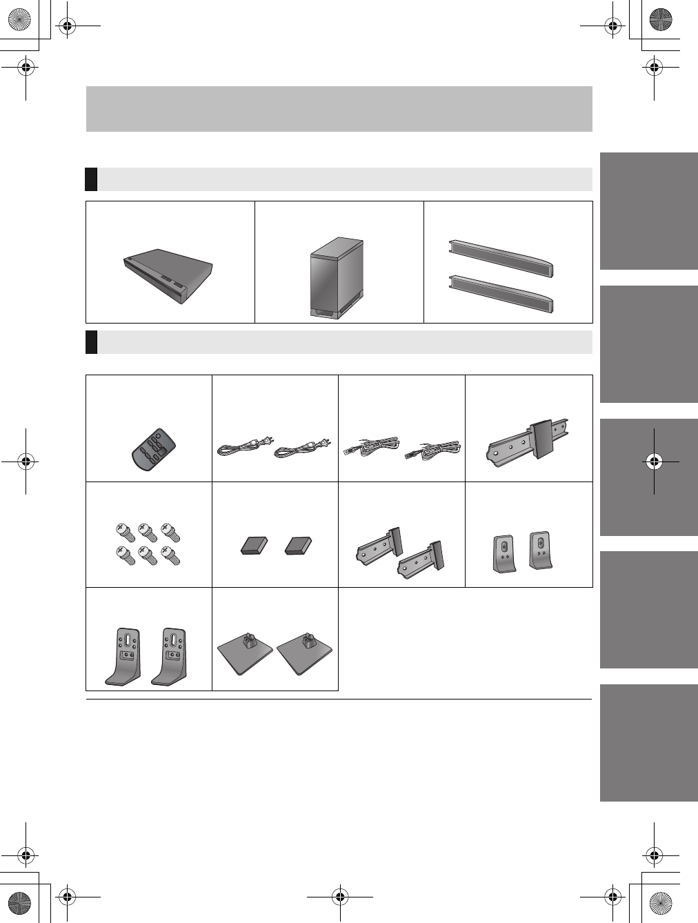
Supplied items
Check the supplied accessories before using the system.
≥Product numbers are correct as of December 2011. These may be subject to change.
≥For U.S.A. and Puerto Rico:
To order accessories, refer to “Accessory Purchases (United States and Puerto Rico)” on page 34.
For Canada: To order accessories, call the dealer from whom you have made your purchase.
≥The supplied AC power supply cord is for use with this unit and the active subwoofer only.
Do not use it with other equipment. Also, do not use cords from other equipment with this unit or active subwoofer.
≥The illustrations shown may differ from your unit.
≥Operations in this Owner’s Manual are described mainly with the remote control, but you can
perform the operations on the main unit if the controls are the same.
System (SC-HTB550)
∏1Main unit
(SU-HTB550)
∏1 Active subwoofer
(SB-HWA550)
∏2 Front speakers
(SB-HTB550)
Accessories
∏1 Remote control
(with a battery)
(N2QAYC000063)
∏2 AC power supply
cords
(K2CB2YY00059)
∏2 Speaker cables
(REEX1266A: RED)
(REEX1267A: WHITE)
Length: 3 m (9.8 ft)
∏1 Speaker joint
(RAQ0085)
∏6 Screws
(XYN5+J14FJK)
∏2 Speaker feet
(RKAX0028-K)
∏2 Front ornaments
(RAQ0089)
∏2 Support legs
(RYQ0970-K)
∏2Stands
(RYQ0853-KJ)
∏2 Speaker bases
(RAQ0086)
(ONLY FOR CANADA)
The enclosed French Canadian label sheet
corresponds to the English display on the remote
control and the top and rear of the main unit and
active subwoofer.
SC-HTB550_RQT9660_mst.book Page 5 Tuesday, December 20, 2011 1:55 PM
6RQT9660
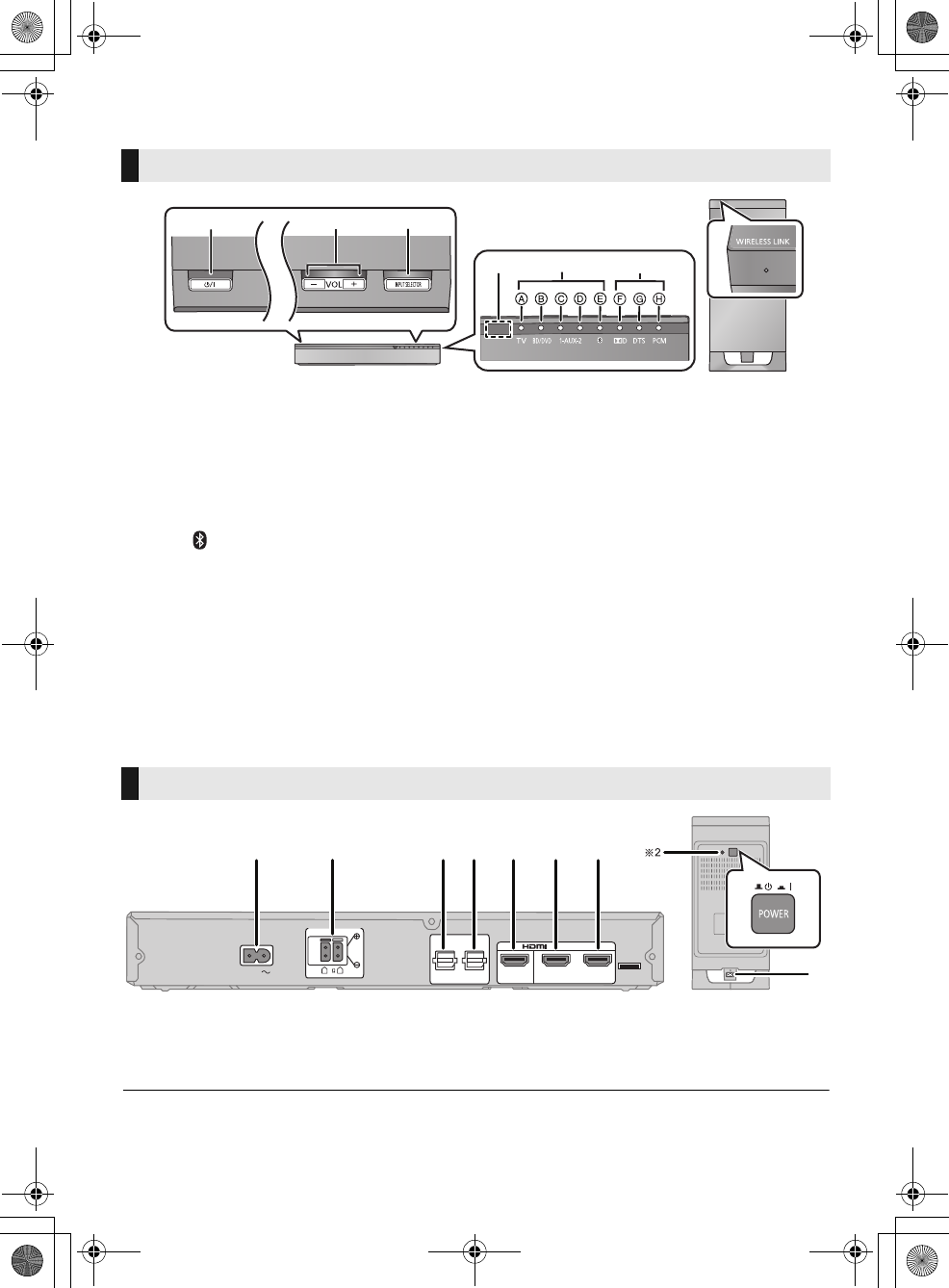
Control reference guide
1Standby/on switch (Í/I)
Press to switch the unit from on to standby
mode or vice versa. In standby mode, the unit
is still consuming a small amount of power.
2 Adjust the volume of the speakers
3 Select the input source
“TV”#“BD/DVD”#“AUX1”
^--- “”(-- “AUX2”(}
4 Remote control signal sensor (>7)
5 Input selector indicators§1
ATV indicator
Lights green when the TV is the audio
source
BBD/DVD indicator
Lights amber when the device connected
to the BD/DVD terminal is the audio
source
CAUX1 indicator
Lights amber when the device connected
to the AUX1 terminal is the audio source
DAUX2 indicator
Lights amber when the device connected
to the AUX2 terminal is the audio source
EBluetooth® indicator
Lights blue when the Bluetooth® device is
the audio source
6 Audio format indicators§1
FDolby Digital indicator
Lights when Dolby Digital is the current
audio format
GDTS indicator
Lights when DTS is the current audio
format
HPCM indicator
Lights when PCM (2ch, Multi-channel) is
the current audio format
7 WIRELESS LINK indicator (>22)
1 AC IN terminal (>21)
2 Speaker terminals (>21)
3 TV terminal (>19)
4 AUX2 terminal (>20)
5 HDMI OUT terminal (ARC compatible) (>19)
6 BD/DVD terminal (>20)
7 AUX1 terminal (>20)
8 Active subwoofer on/off button
§1 The indicators will also blink in various conditions (>30)
§2 The I/D SET button is only used when the main unit is not paired with the active subwoofer (>29)
Main unit and active subwoofer (Front)
7
12
56
3
4
Main unit Active subwoofer
Main unit and active subwoofer (Rear)
8
1
21 34567
SPEAKERS / HAUT-PARLEURS
6
R L
AV OUT
AV IN
DIGITAL
AUDIO
IN
TV
(OPT1)
AUX2
(OPT2) TV (ARC)
BD/DVD
(HDMI1)
BD/DVD
(HDMI1)
AUX1
(HDMI2)
AC IN
SC-HTB550_RQT9660_mst.book Page 6 Tuesday, December 20, 2011 1:55 PM
Before use
RQT9660 7
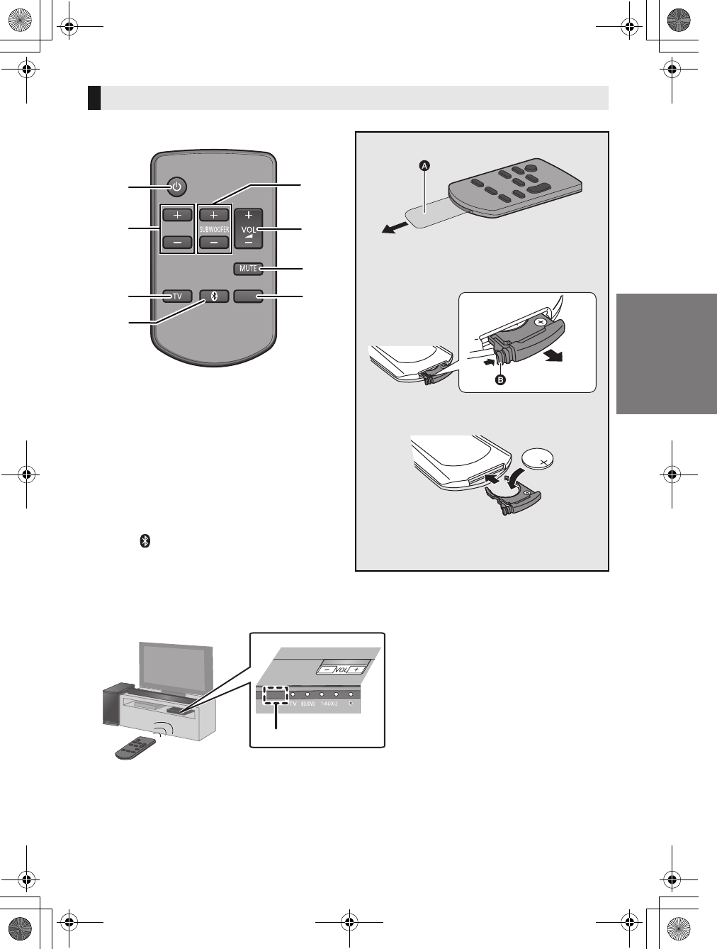
1 Turn the main unit on or off (>23)
2 Adjust the dialog effect level (>23)
3 Adjust the output level of the active subwoofer
(bass sound) (>23)
4 Adjust the volume of this system (>23)
5 Mute the sound (>23)
6 Select the TV as the source (>23)
7 Select the Bluetooth® device as the source
(>23)
8 Select the input source (>23)
“TV”#“BD/DVD” #“AUX1”
^--- “”(-- “AUX2”(}
Remote control
DIALOG LEVEL
LINK MODE
PAIRING
----
1
6
7
2
3
4
5
8
INPUT
SELECTOR
Remove the insulation sheet before using.
∫To replace a button-type battery
1While pressing the stopper , pull out the
battery holder.
2Set the button-type battery with its (i) mark
facing upward and then put the battery
holder back in place.
≥When replacing the battery, use:
CR2025 (Lithium battery)
≥Keep the button-type battery out of reach of
children to prevent swallowing.
∫Remote control operation range
The remote control signal sensor is located on the main unit.
≥Use the remote control within the correct operation range.
Remote control signal sensor
≥Operation range
Distance: Within approx. 7 m
(23 ft) directly in front
Angle: Approx. 30oleft and right
SC-HTB550_RQT9660_mst.book Page 7 Tuesday, December 20, 2011 1:55 PM
8RQT9660
Getting started
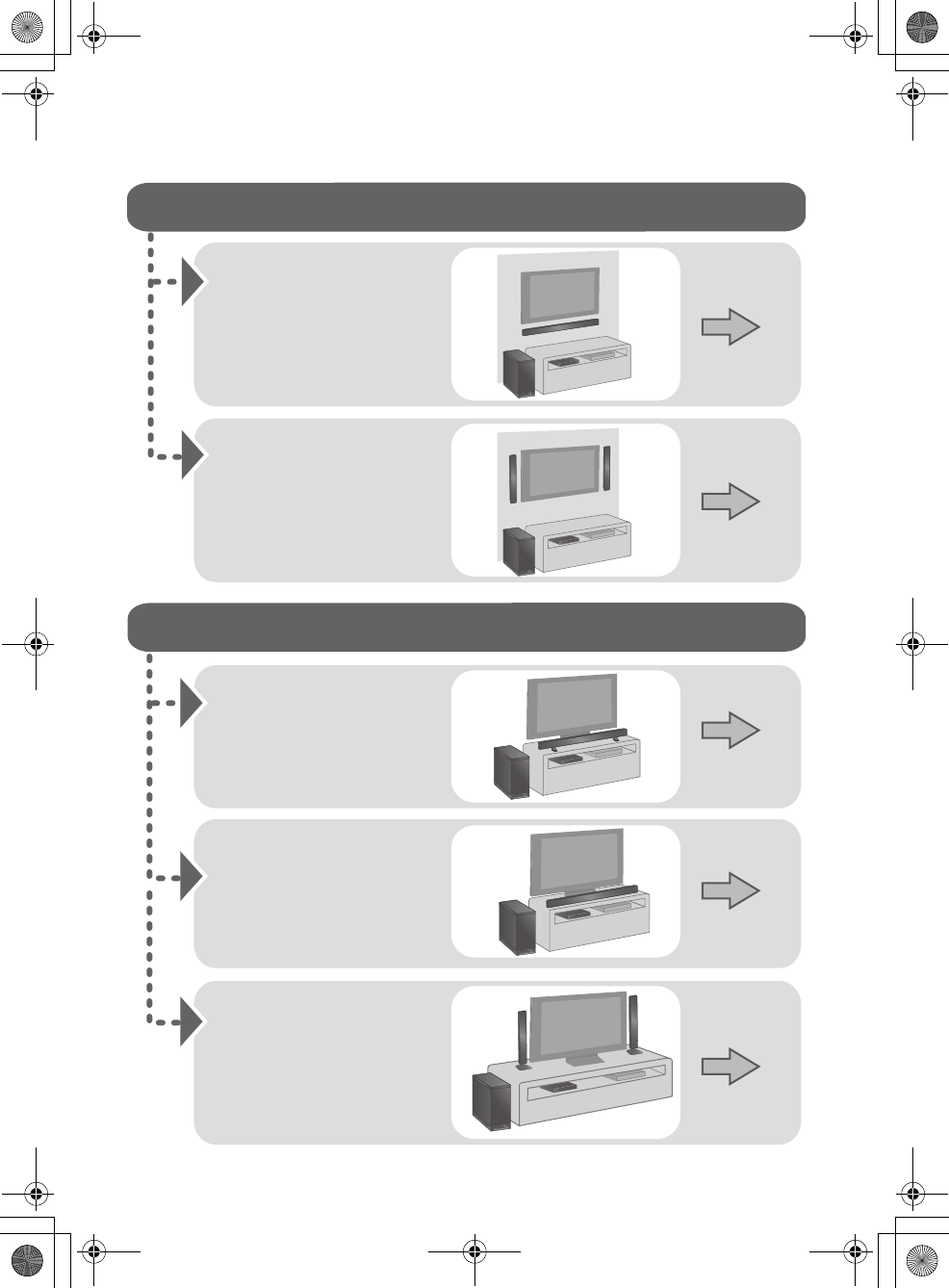
Step 1 Selecting the placement method
≥Choose a placement method that suits you best.
When attaching the speakers to a wall
When placing the speakers on a table
Place the speakers
horizontally
Page 10
Place the speakers
vertically
Place the speakers using
the stands
Place the speakers using
the speaker bases
Page 12
Page 14
Page 15
Page 16
Place the speakers
using the support legs
and speaker feet
SC-HTB550_RQT9660_mst.book Page 8 Tuesday, December 20, 2011 1:55 PM
Getting started
RQT9660 9
≥Use a screwdriver (i) for assembling the speakers.
≥Do not hold the speakers in one hand to avoid injury, you may drop the speakers when carrying them.
When carrying the active subwoofer
To avoid interference, maintain the following distances between the main unit/active subwoofer
and other electronic devices that use the same radio frequency (2.4 GHz and 5 GHz band).
≥Place the active subwoofer within a few meters of the main unit and in a horizontal position with the top panel faced upward.
≥Do not use the main unit or active subwoofer in a metal cabinet.
≥Placing the active subwoofer and the speakers too close to the walls and corners can result in excessive bass. Cover walls
and windows with thick curtains.
≥If irregular coloring occurs on your TV, turn the TV off for about 30 minutes. If it persists, move the speakers further away from
the TV.
≥Keep magnetized items away. Magnetized cards, watches, etc., can be damaged if placed too close to the active subwoofer
and the speakers.
Caution
≥This system is to be used only as indicated in these instructions. Failure to do so may lead to damage to the
amplifier and/or the speakers, and may result in the risk of fire. Consult a qualified service person if damage
has occurred or if you experience a sudden change in performance.
≥Do not attempt to attach these speakers to a wall using methods other than those described in this manual.
Speaker system
∫When attaching the speakers to a wall
The wall or pillar on which the speakers are to be attached should be capable of supporting 33 kg (72.8 lbs) per screw.
Consultation with a qualified building contractor is recommended when attaching the speakers to a wall. Improper attachment
may result in damage to the wall and speakers, and personal injury.
∫When placing the speakers in front of the TV
The speakers may block or interfere with the TV’s various sensors (C.A.T.S. (Contrast Automatic Tracking System) sensor,
remote control sensor, etc.) and the 3D Eyewear transmitters on a 3D compatible TV.
≥If the stands are being used
Move the speakers further away from the TV. If the TV still does not function properly, try removing the stands.
≥If the stands are not used
Move the speakers further away from the TV. If the TV still does not function properly, try placing them beside the TV (>8).
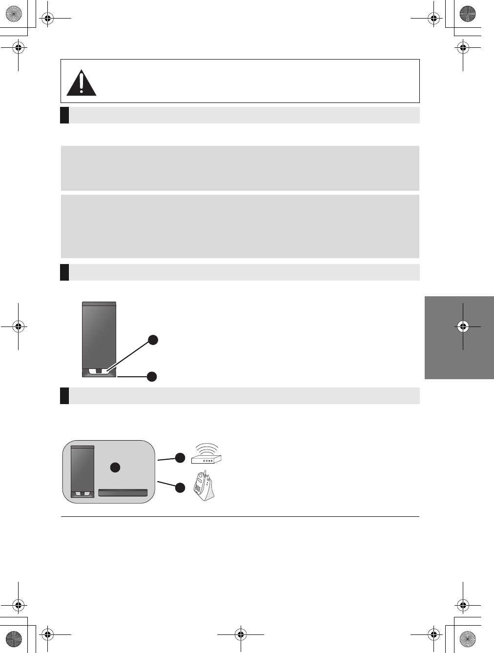
Active subwoofer
Do not hold the active subwoofer from this
opening.
The parts inside (speaker unit) may be damaged.
Always hold the bottom of the active subwoofer when
moving it.
Wireless interference
Main unit/active subwoofer
Wireless LAN: approx. 2 m (6 1/2 ft)
Cordless phone and other electronic devices:
approx. 2 m (6 1/2 ft)
A
B
D
E
C
SC-HTB550_RQT9660_mst.book Page 9 Tuesday, December 20, 2011 1:55 PM
10 RQT9660
Step 2 Assembling the speakers
≥For a safety measure to prevent the speakers from falling, refer to page 17.
≥To prevent damage or scratches, lay down a soft cloth and perform the assembly on it.
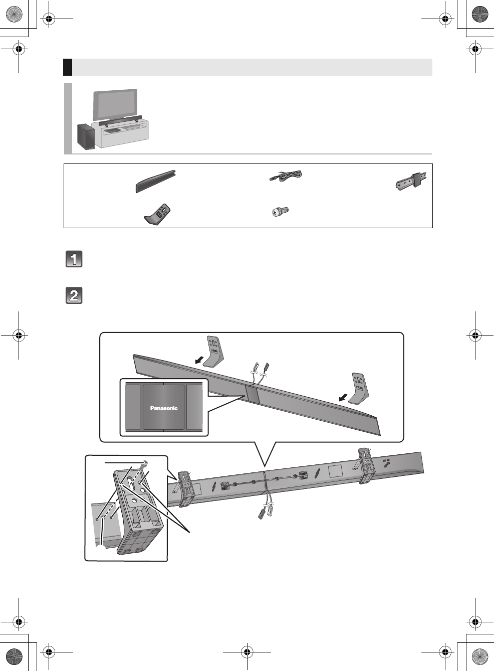
Assemble the speakers.
≥The two speakers are interchangeable.
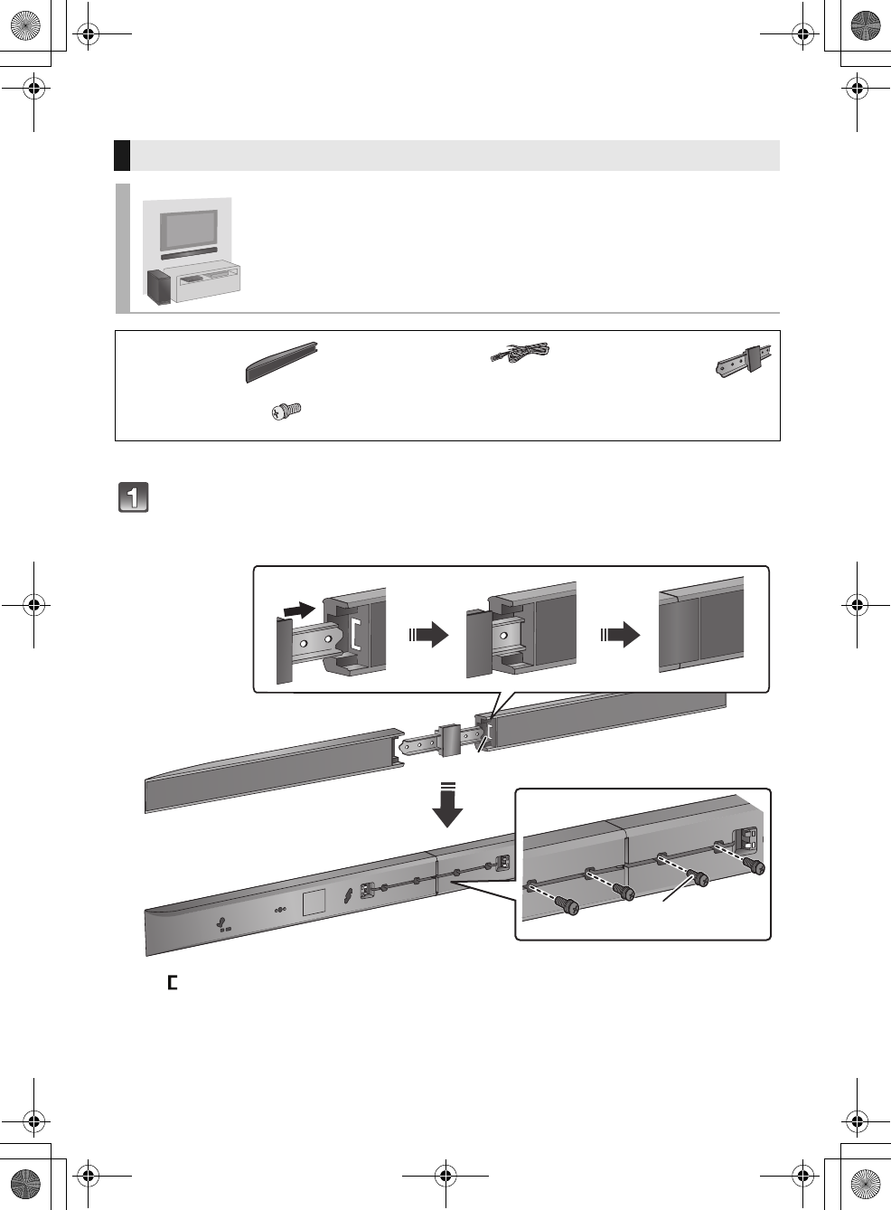
When attaching the speakers to a wall
Place the speakers horizontally
∏2 Speakers ∏2 Speaker cables
(L): WHITE
(R): RED
∏1 Speaker joint
∏4 Screws
“”
shaped slit
≥Insert the speaker joint fully into the slit.
Screw (supplied)
≥Be sure to insert the screws following the order as indicated in the illustration.
≥Keep the screws out of reach of children to prevent swallowing.
2
4
13
SC-HTB550_RQT9660_mst.book Page 10 Tuesday, December 20, 2011 1:55 PM
Getting started
RQT9660 11
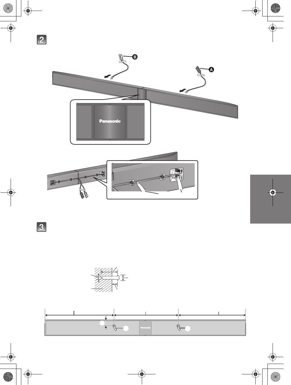
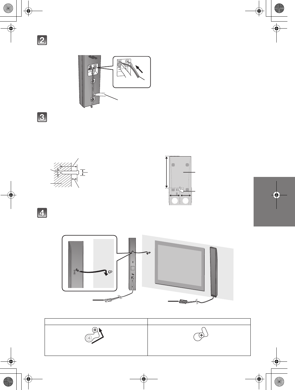
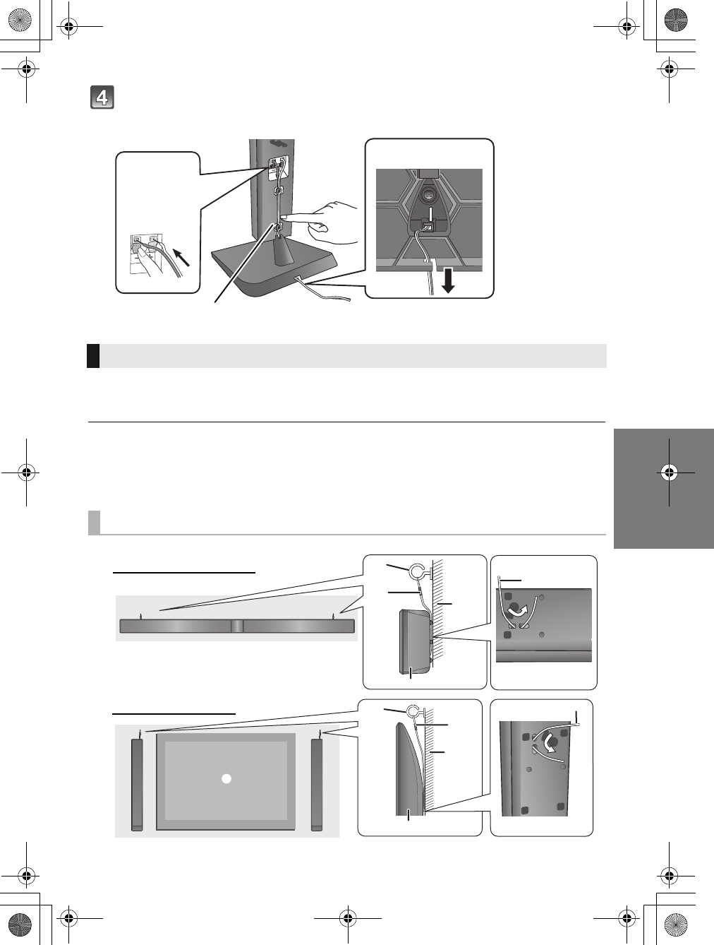
Connect the speaker cables.
≥Use the “Panasonic” logo to identify the left and right speakers, then connect the cables (as illustrated).
≥Insert the wire fully, taking care not to insert beyond the wire insulation.
Drive a screw into the wall.
≥Use the measurements indicated below to identify the screwing positions on the wall.
≥Leave at least 20 mm (25/32q) of space above and on each side of the speaker to allow enough space for fitting the
speaker.
≥The position on the wall where the screw is to be attached, as well as the screw, should be capable of supporting over
33 kg (72.8 lbs).
≥Keep the screws out of reach of children to prevent swallowing.
1Insert the wire
fully.
r: White
s: Blue line
2Press into the
groove.
RED: Right speaker channel (R)
WHITE: Left speaker channel (L)
At least 30 mm (1 3/16q)
‰4.0 mm (5/32q)
‰7.0 mm to ‰9.4 mm (9/32q to 3/8q)
Wall or pillar
5.5 mm to 6.5 mm (7/32q to 1/4q)
326 mm (12 27/32q)316 mm (12 7/16q)316 mm (12 7/16q)26 mm (1 1/16q)
Wall mounting hole
White
Red
Push
Front view (semi-transparent image)
SC-HTB550_RQT9660_mst.book Page 11 Tuesday, December 20, 2011 1:55 PM
12 RQT9660
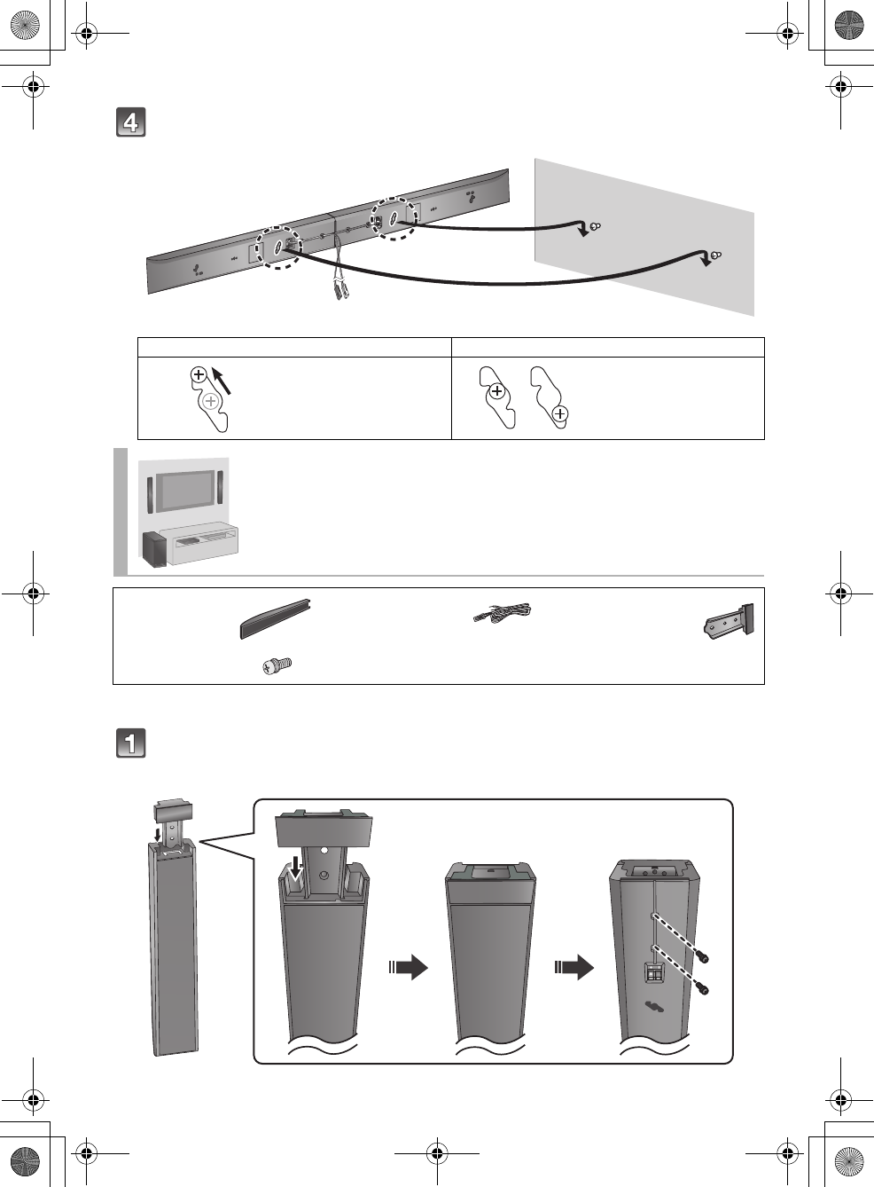
Fit the speaker securely onto the screw(s).
≥For a safety measure to prevent the speakers from falling, refer to page 17.
≥To prevent damage or scratches, lay down a soft cloth and perform the assembly on it.
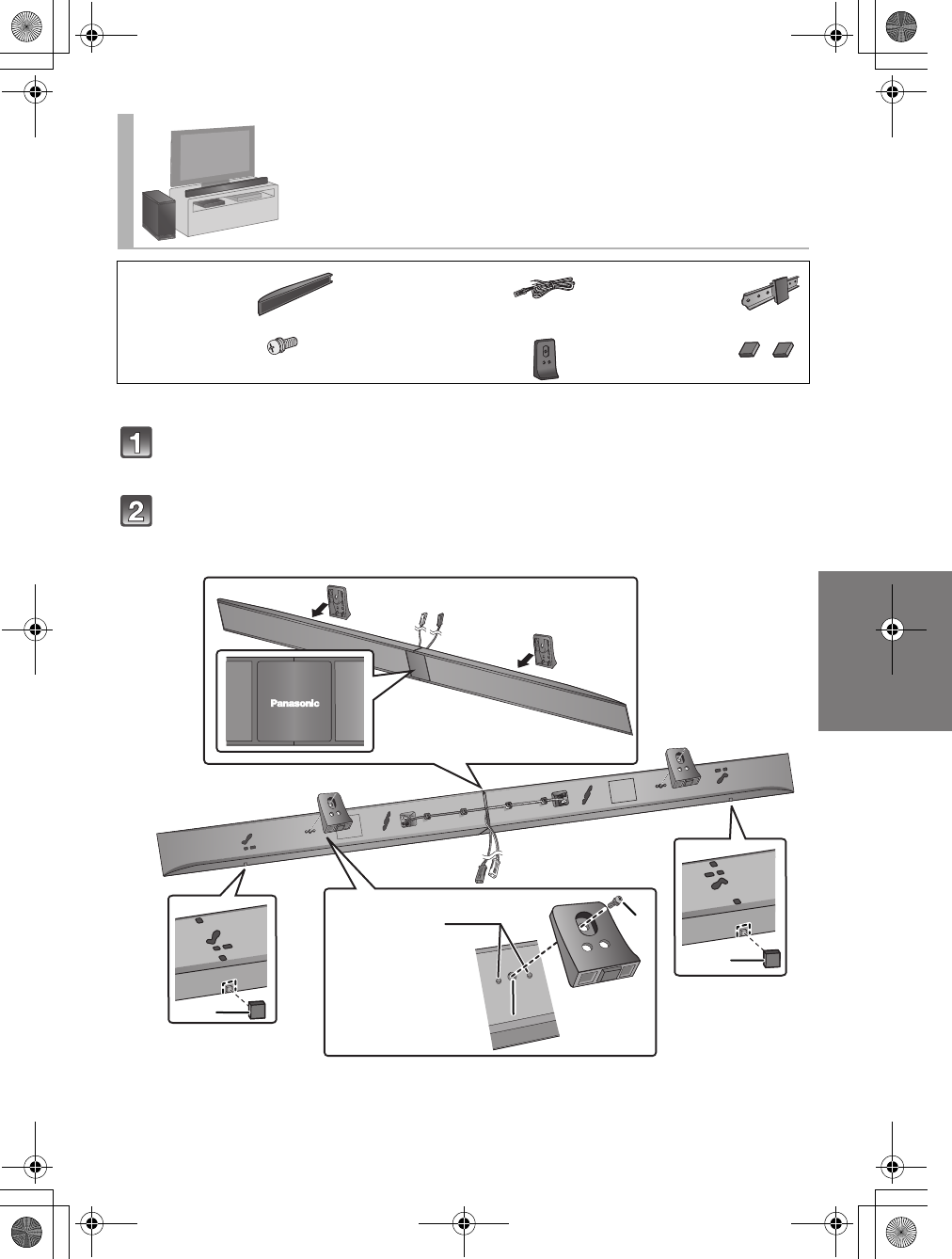
Attach the front ornaments.
≥The two speakers are interchangeable.
≥Keep the screws out of reach of children to prevent swallowing.
DO DO NOT
≥Move the speaker so
that the screw is in this
position.
≥In this position, the
speaker will likely fall if
moved to the left or right.
Place the speakers vertically
∏2 Speakers ∏2 Speaker cables
(L): WHITE
(R): RED
∏2 Front ornaments
∏4 Screws
Front view Rear view
SC-HTB550_RQT9660_mst.book Page 12 Tuesday, December 20, 2011 1:55 PM
Getting started
RQT9660 13
Connect the speaker cables.
≥Insert the wire fully, taking care not to insert beyond the wire insulation.
Drive a screw into the wall.
≥Use the measurements indicated below to identify the screwing positions on the wall.
≥Leave at least 20 mm (25/32q) of space above and on each side of the speaker to allow enough space for fitting the
speaker.
≥The position in the wall where the screw is to be attached as well as the screw should be capable of supporting over 33 kg
(72.8 lbs).
≥Keep the screws out of reach of children to prevent swallowing.
Fit the speaker(s) securely onto the screw(s).
≥Place the speaker that is connected with the speaker cable with a red connector on the observers’ right, and connect with
the speaker cable with a white connector on the observers’ left.
1 Insert the wire fully.
r: White
s: Blue line
2 Press into the groove.
At least 30 mm (1
3
/
16
q
)
‰4.0 mm (5/32q)
‰7.0 mm to ‰9.4 mm
(9/32q to 3/8q)
Wall or pillar
5.5 mm to 6.5 mm
(7/32q to 1/4q)
Front speaker
(Rear view)
102 mm (4 1/32q)
37 mm (1 15/32q)
Wall mounting
hole
WHITE: Left speaker channel (L) RED: Right speaker channel (R)
DO DO NOT
≥Move the speaker so that the screw is in this
position.
≥In this position, the speaker will likely fall if moved to
the left or right.
Push
Red
White
SC-HTB550_RQT9660_mst.book Page 13 Tuesday, December 20, 2011 1:55 PM
14 RQT9660
≥For a safety measure to prevent the speakers from falling, refer to page 17.
≥To prevent damage or scratches, lay down a soft cloth and perform the assembly on it.
Assemble the speakers following steps 1 and 2 of “Place the speakers
horizontally” (>10).
Attach the stands.
≥Use the “Panasonic” logo to identify the top and bottom of the speaker.
≥Keep the screws out of reach of children to prevent swallowing.
When placing the speakers on a table
Place the speakers using the stands
∏2 Speakers ∏2 Speaker cables
(L): WHITE
(R): RED
∏1 Speaker joint
∏2 Stands ∏6 Screws
Screw (supplied)
Screw hole
Align the holes with the projecting parts on the speaker.
≥Do not use the lower holes for the alignment. If these holes
are used, the screw does not fit.
SC-HTB550_RQT9660_mst.book Page 14 Tuesday, December 20, 2011 1:55 PM
Getting started
RQT9660 15
≥For a safety measure to prevent the speakers from falling, refer to page 17.
≥To prevent damage or scratches, lay down a soft cloth and perform the assembly on it.
Assemble the speakers following steps 1 and 2 of “Place the speakers
horizontally” (>10).
Attach the support legs and speaker feet.
≥Use the “Panasonic” logo to identify the top and bottom of the speaker.
≥Keep the screws and the speaker feet out of reach of children to prevent swallowing.
Place the speakers using the support legs and
speaker feet
∏2 Speakers ∏2 Speaker cables
(L): WHITE
(R): RED
∏1 Speaker joint
∏6 Screws ∏2 Support legs ∏2 Speaker feet
Screw (supplied)
Screw hole
Speaker foot (supplied)
≥Attach the speaker foot directly below the wall mounting hole (as illustrated).
Align the
projecting parts
on the speaker
with support leg.
SC-HTB550_RQT9660_mst.book Page 15 Tuesday, December 20, 2011 1:55 PM
16 RQT9660
≥For a safety measure to prevent the speakers from falling, refer to page 17.
≥To prevent damage or scratches, lay down a soft cloth and perform the assembly on it.
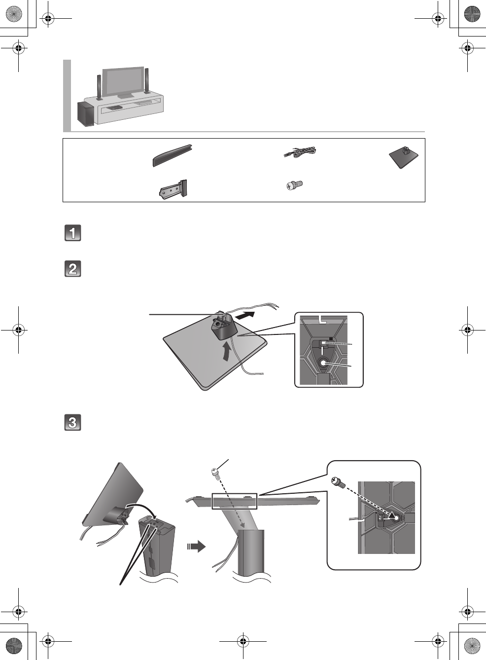
Assemble the speakers following step 1 of “Place the speakers
vertically” (>12).
Insert the speaker cable through the base.
≥Be sure to insert the speaker cable through the threading hole as indicated in the illustration. (If the speaker cable is
twisted, it might not fit through the opening. Straighten the speaker cable before inserting.)
Attach the speaker to the base.
≥The two speakers are interchangeable.
≥Keep the screws out of reach of children to prevent swallowing.
Place the speakers using the speaker
bases
∏2 Speakers ∏2 Speaker cables
(L): WHITE
(R): RED
∏2 Bases
∏2 Front ornaments ∏6 Screws
Threading hole Screw hole
Position the cable
between the ridges.
≥Leave about
110 mm (4 21/64q)
Screw (supplied)
≥Tighten securely.
Align the projecting parts with the holes on the speaker.
SC-HTB550_RQT9660_mst.book Page 16 Tuesday, December 20, 2011 1:55 PM
Getting started
RQT9660 17
Connect the speaker cables.
≥Insert the wire fully, taking care not to insert beyond the wire insulation.
≥Place the speaker that is connected with the speaker cable with a red connector on the observers’ right, and connect with
the speaker cable with a white connector on the observers’ left.
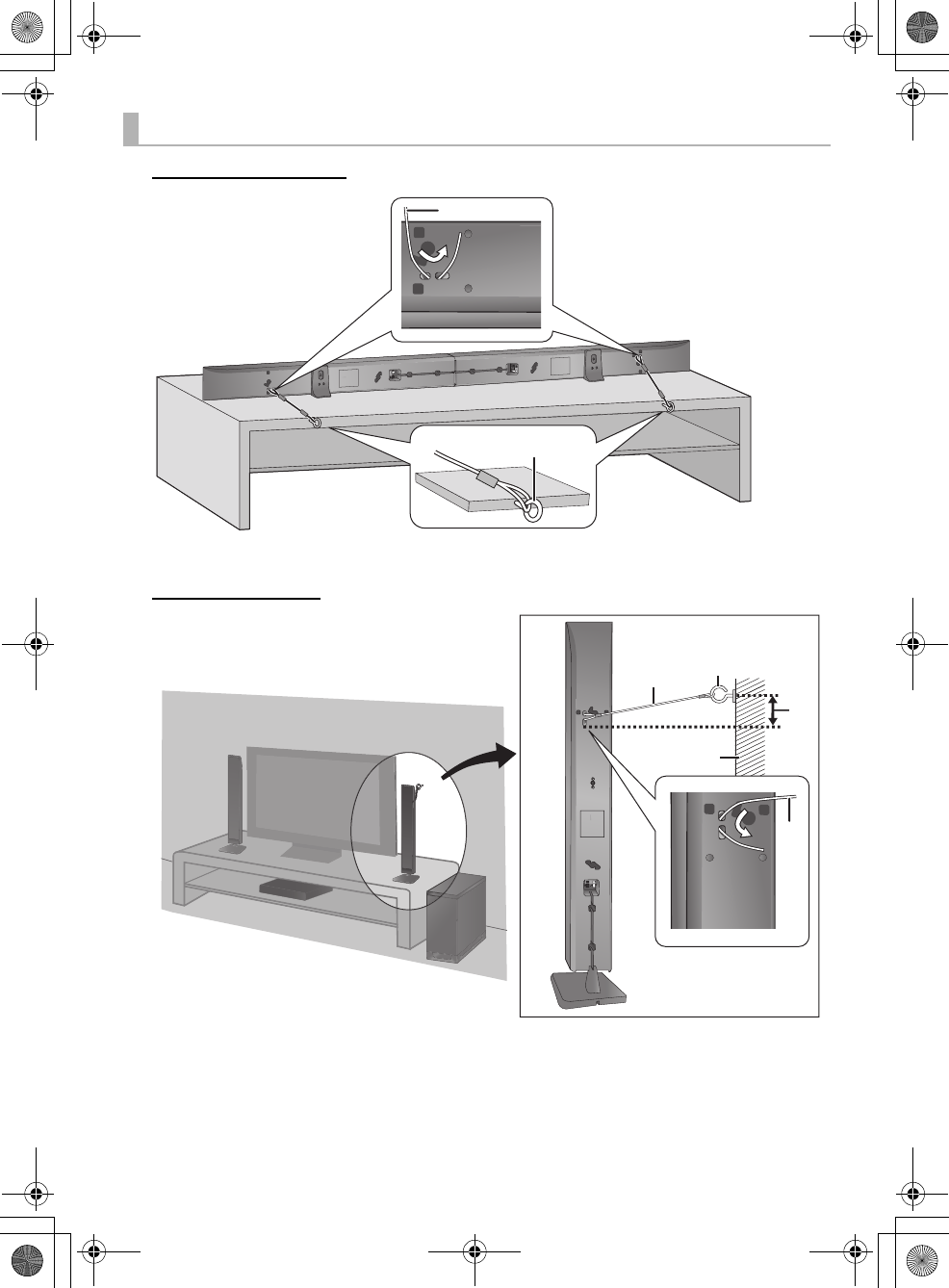
To prevent the speakers from falling, it is recommended, as an additional
protection measure, to attach the speakers to the wall or table with a fall
prevention cord (hereafter “cord”).
≥Consultation with a qualified housing contractor concerning the appropriate procedure when attaching to a concrete wall or a
surface that may not have strong enough support is recommended (>11, 13). Improper attachment may result in damage to
the wall and speakers, and personal injury.
≥Use a cord of less than ‰2.0 mm (5/64q), which is capable of supporting over 10 kg (22.05 lbs).
≥Keep the screws out of reach of children to prevent swallowing.
≥Make sure that the slack of the cord is minimal.
Additional speaker fall prevention measures
When attaching the speakers to a wall
Cord Screw eye Wall TV
Insert the
wire fully.
r: White
s: Blue line
Press into the groove.
Push
Back of the base
Wall-mounted speakers
Horizontal placement
Wall-mounted speakers
Vertical placement
SC-HTB550_RQT9660_mst.book Page 17 Tuesday, December 20, 2011 1:55 PM
18 RQT9660
When placing the speakers on a table
Horizontal placement
Vertical placement
Cord
Screw eye
≥Depending on the placement of the speakers, the
screwing position of the screw eye may differ.
Wall
Approx. 150 mm (5 29/32q)
SC-HTB550_RQT9660_mst.book Page 18 Tuesday, December 20, 2011 1:55 PM