Panasonic of North America 5Z6KX-P8415 Color Laser Printer With Parallel Port User Manual Instructions
Panasonic Corporation of North America Color Laser Printer With Parallel Port Instructions
User Manual

EXHIBIT #6
Fty Control No.: KM6-99-F008
FCC ID : ACJ5Z6KX-P8415
OPERATING INSTRUCTIONS
Setup Guide
Model No. KX-P8415
Color Laser Printer
and Reference Guide
Setup Guide . . . . . . . . . . . . . . .3
Before You Start
Setup
Reference Guide . . . . . . . . . . .17
Loading Media
Settings and Printing
Maintenance
Appendix
This manual includes Setup Guide and Reference Guide.
Setup Guide:
describes basic setup procedures for the Panasonic KX-P8415 Color Laser Printer
and necessary precautions for safety and use. First read this guide to setup the printer.
Reference Guide: describes the instructions in outline for printing on a media (transparency, label
or envelope), troubleshooting, etc.
For other detailed information, refer to Operating Instructions installed on your computer.
It is automatically installed on your computer when installing the KX-P8415 software (see page 13).
If the Acrobat Reader application has not been installed in your computer, you are required to
install it so that you can read the documentation (see page 13).
Please carefully read this manual and keep this documentation in a safe place for future reference.
Keep this manual near the
printer for quick reference.
Setup Guide
Model No.
KX-P8415
Color Laser PrinterColor Laser Printer
and Reference Guide
Using Manuals:
(QUICK START)

2
End-User License Agreement
THIS IS A LEGAL AGREEMENT BETWEEN YOU
AND PANASONIC. CAREFULLY READ ALL THE
TERMS AND CONDITIONS OF THIS
AGREEMENT PRIOR TO OPENING THE PACKET
OF SOFTWARE PROGRAM. OPENING THE
PACKET INDICATES YOUR ACCEPTANCE OF
THESE TERMS AND CONDITIONS. If you do not
agree to these terms and conditions, return the
unopened packet and the other components of the
Panasonic product to the place of purchase and
your money will be refunded. No refunds will be
given for the products that have an opened packet
or missing components.
1. COPYRIGHT:
Panasonic has the right to license or has been
granted to license the enclosed Software
Program (“SOFTWARE”), developed and
copyrighted by Kyushu Matsushita Electric Co.,
Ltd. or its licensor (“Licensor”). You
acknowledge that you are receiving only a
LIMITED LICENSE TO USE the SOFTWARE
and related documentation, and that you shall
obtain no title, ownership nor any other rights in
or to the SOFTWARE and related
documentation, all of which title and rights shall
remain with Licensor and Panasonic.
2. LICENSE:
(1) You have the non-exclusive rights to use the
SOFTWARE on your computer. (2) If you wish to
use the SOFTWARE in your network, you may
install the SOFTWARE into a network server
and/or its clients and use the copies of
SOFTWARE in your network. (3) You may make
reasonable quantities of copies of the
SOFTWARE solely for backup or archival
purposes. (4) You may not rent or lease the
SOFTWARE, but you may transfer your right
under this License Agreement on a permanent
basis, provided that you transfer this Agreement,
all copies of the SOFTWARE, all related
documentation and your Panasonic product, and
the recipient thereof agrees to the terms of this
Agreement. (5) You may not reverse engineer,
decompile or disassemble the SOFTWARE,
except that in European Union and European
Free Trade Association, you may have the
limited right to reverse engineer, decompile or
disassemble the SOFTWARE solely to the
extent specifically permitted by the terms and
conditions of Article 6 of the European
Community’s Directive for the Legal Protection
of Computer Programs, OJL 122/42 (17 May
1991). (6) You may not use, copy, modify, alter
or transfer the SOFTWARE, any copy thereof or
its related documentation, in whole or in part,
except as expressly provided in this Agreement.
3. TERM:
This license is effective until terminated. You may
terminate this Agreement at any time by
destroying the SOFTWARE and related
documentation and all copies thereof. This
license will also terminate if you fail to comply
with any term or condition of this Agreement.
Upon such termination, you agree to destroy all
copies of the SOFTWARE and related
documentation.
4. LIMITED WARRANTY:
Within ninety (90) days of your receipt of the
SOFTWARE, Panasonic warrants that the
storage media on which the SOFTWARE are
furnished is free from defect in materials and
workmanship under normal use, and that it will
repair or at its option replace any defective media
at no charge to you, provided that such defective
media is returned to Panasonic within such
ninety (90) days period.
5. LIMITATION OF LIABILITY:
EXCEPT AS STATED ABOVE, NEITHER
PANASONIC NOR PANASONIC’S SUPPLIER
MAKES OR PASSES ON TO YOU OR OTHER
THIRD PARTY, ANY WARRANTY OR
REPRESENTATION INCLUDING, BUT NOT
LIMITED TO, THE IMPLIED WARRANTY OF
MERCHANTABILITY AND FITNESS FOR A
PARTICULAR PURPOSE. WITHOUT LIMITING
THE GENERALITY OF THE FOREGOING,
NEITHER PANASONIC NOR PANASONIC’S
SUPPLIER WARRANTS THAT THE
SOFTWARE WILL BE ERROR-FREE OR THAT
IT WILL MEET YOUR REQUIREMENTS.
NEITHER PANASONIC NOR PANASONIC’S
SUPPLIER SHALL BE LIABLE FOR ANY
DAMAGE SUFFERED BY YOU INCLUDING,
BUT NOT LIMITED TO, CONSEQUENTIAL,
INCIDENTAL SPECIAL OR PUNITIVE
DAMAGES. THE ABOVE LIMITATIONS SHALL
APPLY REGARDLESS OF THE FORM OF
ACTION WHETHER IN CONTRACT, TORT
(INCLUDING NEGLIGENCE), STRICT
PRODUCT LIABILITY OR OTHERWISE, EVEN
IF SUCH PARTY HAS BEEN ADVISED OF THE
POSSIBILITY OF SUCH DAMAGES.
End-User License Agreement . . . . .2
For Your Safety . . . . . . . . . . . . . . . . .4
Cautions . . . . . . . . . . . . . . . . . . . . . . .7
System Requirements . . . . . . . . . . .8
Minimum Space Requirements . . . .8
Power Source . . . . . . . . . . . . . . . . . .8
Unpacking . . . . . . . . . . . . . . . . . . . . .9
Part Names . . . . . . . . . . . . . . . . . . . .9
Setting Up the Printer . . . . . . . . . . .10
Connecting the Printer to
a Computer . . . . . . . . . . . . . . . . .11
Loading Media in the Media Tray . .11
Installing the KX-P8415 Software .13
Reading the Operating Instructions
on the KX-P8415 CD-ROM . . . . .14
Removing the KX-P8415 Software .15
Power On . . . . . . . . . . . . . . . . . . . . .15
Printing a Test Page From
the Printer Panel . . . . . . . . . . . . .15
3
Contents
Before You Start
Setup
Before You Start Setup
Thank you for purchasing the
Panasonic KX-P8415 Color Laser
Printer.
The serial number is located on the label on
the rear of the unit. For your convenience,
record the number below and keep this book
along with your proof of purchase, in the
event of a theft or for future reference.
MODEL NO. KX-P8415
NAME OF RESELLER
SERIAL NO.
DATE OF PURCHASE
As an ENERGY STAR® Partner,
Panasonic has determined that this
product meets the ENERGY STAR®
guidelines for energy efficiency.
(ENERGY STAR is a U.S.registered
mark.)
BMicrosoft, Windows and Windows NT are either
registered trademarks or trademarks of Microsoft
Corporation in the United States and/or other countries.
BPentium is a registered trademark of Intel.
BAdobe, the Adobe logo, Acrobat, and the Acrobat logo
are trademarks of Adobe Systems Incorporated.
BAvery and all other related brands and product names
are trademarks of Avery Dennison Corporation.
B4CC is a trademark of Stora Enso.
BDestinyTM, WinStylerTM Display List Color and WinRefsTM
are trademarks of Destiny Technology Corporation.
BAll other acknowledgements are trademarks or
registered trademarks of their respective holders.
The instructions are subject to change without notice.
WinStylerTM DLC - Copyright 1995-1999, Destiny
Technology Corp. Ver. 1.0 All Rights Reserved.
WinRefsTM Copyright 1994-1999, Destiny Technology
Corp. Ver. 2.0 All Rights Reserved.
Acrobat® Reader copyright © 1987-1999 Adobe Systems
Incorporated. All rights reserved.
© Kyushu Matsushita Electric Co., Ltd. 1999
Setup Guide
Setup Guide
Caution
This printer utilizes a laser. Use of controls or
adjustments or performance of procedures other
than those specified herein may result in
hazardous radiation exposure.
Warning
Make sure that the printer is installed in a well
ventilated room so as not to increase density of
ozone in the air. Since ozone is heavier than air, it
is recommended that air at floor level be ventilated.
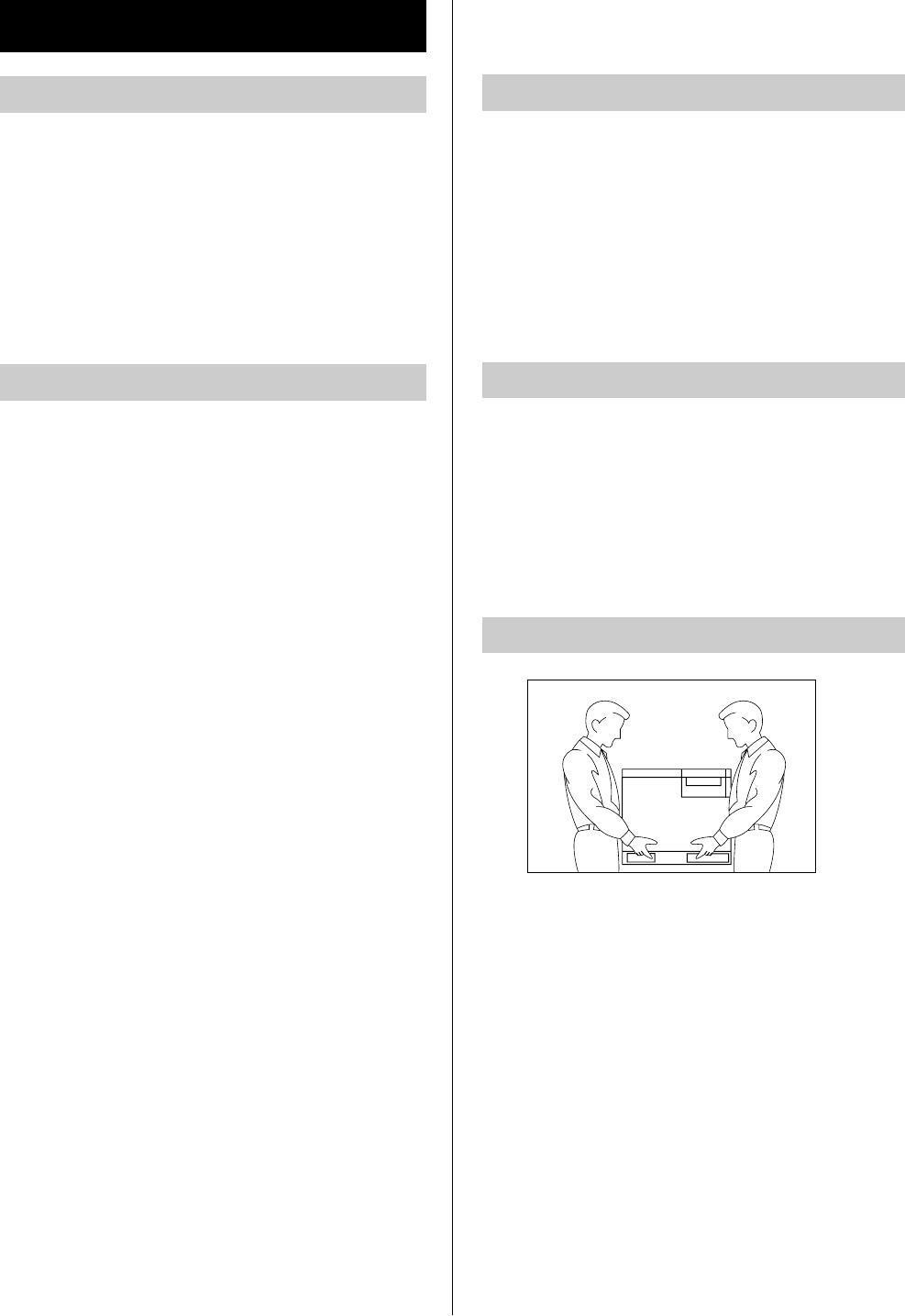
The printer weighs approximately 49.2 kg{108.4
lbs.}. It must be handled by two people. Turn the
power off and remove the power cord when
handling the unit.
4
Ozone Release
Warning
To prevent fire or shock hazard, do not expose this
product to rain or any type of moisture.
Caution
Do not open covers and do not attempt to repair the
unit yourself. Refer servicing to qualified personnel.
Warning
BThe power source voltage of this unit is listed on
the nameplate. Only plug the unit into an outlet
with the proper voltage.
BWhen you operate this equipment, the outlet
should be near the equipment and accessible.
BTo ensure safe operation the AC cord supplied
must be inserted into standard three-prong AC
outlet which is effectively grounded (earthed)
through the normal wiring.
BThe fact that the equipment operates
satisfactorily does not imply that the power point
is grounded (earthed) and that the installation is
completely safe. For your safety, if in any doubt
about the effective grounding (earthing) of the
power point, consult a qualified electrician.
BIf the plug cannot be inserted into the AC outlet,
contact a licensed electrician to replace the outlet
with a properly grounded (earthed) one.
BDo not defeat the purpose of the grounding
(earthing) plug (ex. do not use a conversion
plug).
For Your Safety
General
Moving the Unit
Laser Safety
Power Source
5
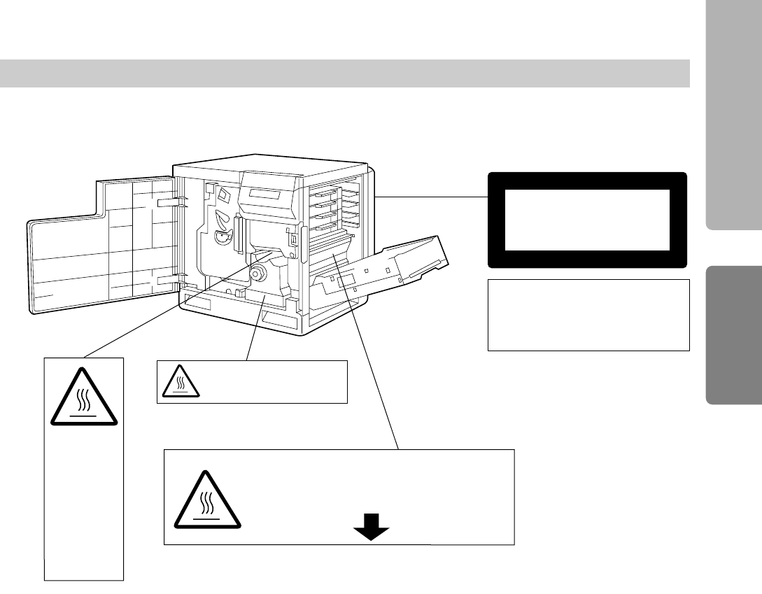
CAUTION:
HOT SURFACE
INSIDE
ATTENTION:
SURFACE
CHAUDE
CI-INTERIEUR
VORSICHT:
HEISSE FLÄCHE
INTERN
ATENCION:
SUPERFICIE
CALIENTE
EN EL INTERNO
CAUTION:
HOT SURFACE INSIDE
CAUTION:HOT SURFACE BELOW
ATTENTION:SURFACE CHAUDE CI-DESSOUS
VORSICHT:HEIßE OBERFLÄCHE DARUNTER
ATENCION:SUPERFICIE CALIENTE ABAJO
Caution Labels
(220-240 V equipment)
Laser diode properties
Laser output : 5 mW max
Wavelength : 780 nm
Emission duration : Continuous
CLASS
KLASSE
CLASSE
CLASE
1 LASER PRODUCT
1 LASER PRODUKT
1 LASER PRODUIT
1 LÁSER PRODUCTO
Before You Start
Setup Guide
6
FOR USERS IN AUSTRALIA
This mark shows that the product complies with AS/NZS 3548.
FOR USERS IN U.K.
IMPORTANT:
FOR YOUR SAFETY PLEASE READ THE FOLLOWING TEXT CAREFULLY
This printer is supplied with a moulded three pin mains plug each for your safety and convenience. A 13
amp fuse is fitted in this plug. Should the fuse need to be replaced please ensure that the replacement
fuse has a rating of 13 amps and that it is approved by ASTA or BSI to BS 1362.
Check for the ASTA mark or the BSI mark on the body of the fuse.
If the plug contains a removable fuse cover you must ensure that it is refitted when the fuse is replaced.
If you lose the fuse cover the plug must not be used until a replacement cover is obtained.
A replacement fuse cover can be purchased from your local Panasonic Dealer.
IF THE FITTED MOULDED PLUG IS UNSUITABLE FOR THE SOCKET OUTLET IN YOUR HOME
THEN THE FUSE SHOULD BE REMOVED AND THE PLUG CUT OFF AND DISPOSED OF SAFELY.
THERE IS A DANGER OF SEVERE ELECTRICAL SHOCK IF THE CUT OFF PLUG IS INSERTED
INTO ANY 13 AMP SOCKET.
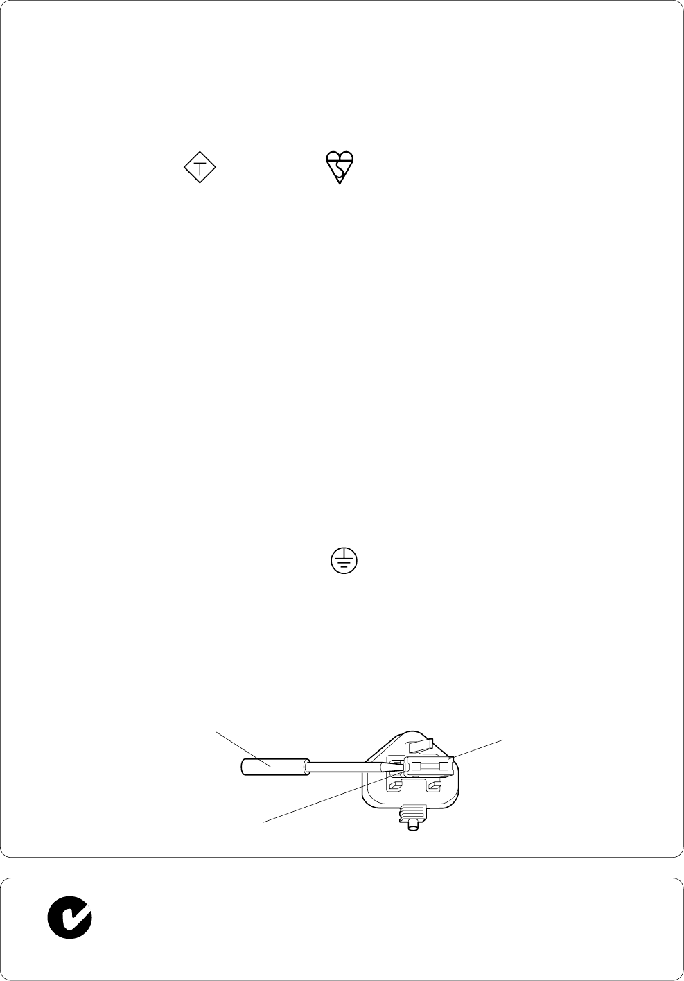
If a new plug is to be fitted please observe the wiring code as shown below.
If in any doubt please consult a qualified electrician.
WARNING: THIS APPLIANCE MUST BE EARTHED.
IMPORTANT: The wires in this mains lead are coloured in accordance with the following code.
Green-and-Yellow: Earth Blue: Neutral Brown: Live
As the colours of the wire in the mains lead of this appliance may not correspond with the coloured
markings identifying the terminals in your plug, proceed as follows.
The wire which is coloured GREEN-AND-YELLOW must be connected to the terminal in the plug which
is marked with the letter E or by the Earth symbol , or coloured GREEN or GREEN-AND-YELLOW.
The wire which is coloured BLUE must be connected to the terminal in the plug which is marked with the
letter N or coloured BLACK.
The wire which is coloured BROWN must be connected to the terminal in the plug which is marked with
the letter L or coloured RED.
How to replace the fuse: Open the fuse compartment with a screwdriver and replace the fuse.
FUSE COVER
SCREWDRIVER
FUSE
N52
ASA
LN
7
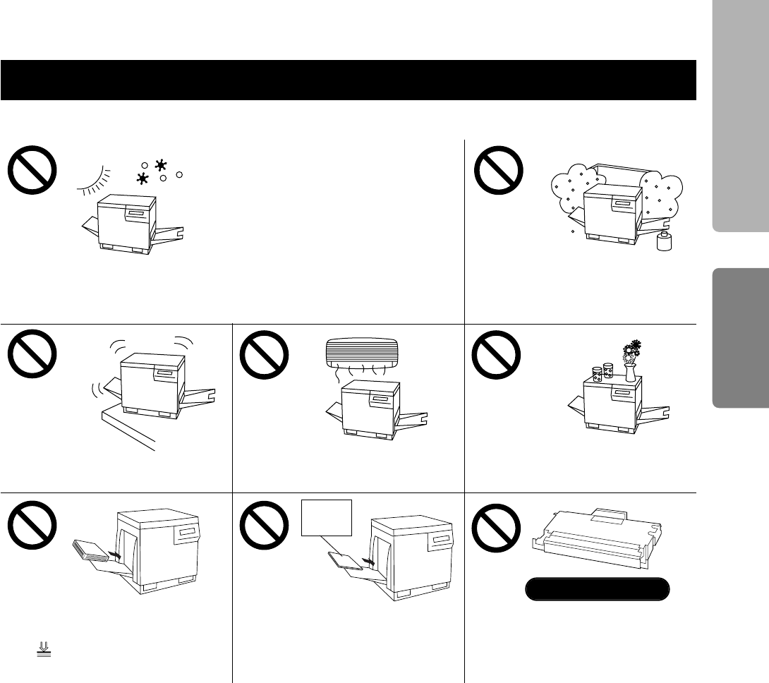
To avoid machine malfunction, do not use the equipment under the following conditions:
BLiquids near the equipment
BUnstable or unlevel surfaces BDirectly in front of air
conditioning vents
Cautions
BDirect exposure to sunlight
BExtremely high or low temperature
[temperature range: 10˚C to 32.5˚C
(50˚F to 90.5˚F)]
BExtremely high or low humidity
(humidity range: 20% to 80% RH)
BCondensation due to rapid change
of temperature
BAreas of poor ventilation
BAreas of high dust or chemical
fume concentration (solvent etc.)
BToo much media/document
which exceeds the limit mark
( ) on the guide of the tray.
BAny toner other than genuine
Panasonic toner; it may
damage the printer.
Not genuine toner
BDo not use a media for ink jet
(paper, transparency, etc.) that
may be wrapped around the
fuser roller and cause damage.
Ink jet
media
■ Static Electricity Damage
To prevent static electricity damage to any of the following components, touch a grounded metal surface,
such as the printer’s bare metal frame prior to touching the component.
BThe interface connectors : parallel and optional network
BElectrical components, connectors inside the printer and any components on the optional board (RAM
Expansion Board or Ethernet Card)
BThe connector pins on the optional 2nd cassette feeder or auto duplex printing unit for the printer
■ Interface Cable
Always use a shielded interface cable. Use of an unshielded cable can result in radio interference with data.
Before You Start
Setup Guide
8
Based on the IEEE P1284-B standard
(An ECP compatible parallel port is recommended for
Windows 95 and Windows 98. To turn on the ECP
mode, use the computer’s BIOS setup. Refer to the
computer’s manual for details.)
System Requirements
PC
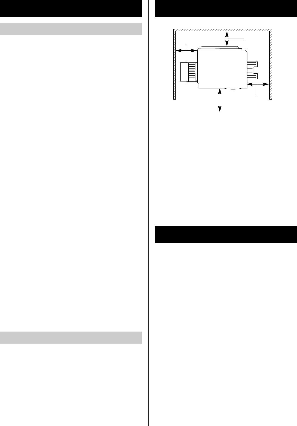
Minimum Space Requirements
Left Right
Power Source
BThe voltage level of the power source must not
vary more than ±10% from the voltage level
marked on the nameplate (located on the rear of
the unit).
BDo not use an extension cord.
BDo not use a line conditioner, transient suppressor
or surge protector as it may cause a machine
error.
To operate the KX-P8415 system effectively, see
the following:
CPU:
Pentium 133 MHz or greater
Operating System:
Windows®95*1, Windows 98*2 or Windows NT®4.0*3
RAM:
16 MB or more (More than 32 MB is recommended.)
Free disk space:
100 MB or more
Virtual memory:
16 MB or more (More than 32 MB is recommended.)
Drive:
CD-ROM drive
*1Microsoft®Windows®95 operating system
(hereafter Windows 95)
*2Microsoft®Windows®98 operating system
(hereafter Windows 98)
*3Microsoft®Windows NT®Workstation operating
system, and Microsoft®Windows NT®Server
network operating system Version 4.0
(hereafter Windows NT 4.0)
Interface
#45 cm (17.7″)
Multi-purpose tray opening space
$35 cm (13.8″)
Controller board opening space
%50 cm (19.7″)
Media tray opening space
&60 cm (23.6″)
Front cover opening space
#$
%
&
9
Make sure that all accessories shown below were
provided and have not been damaged. Report
damage or shortages to the reseller from which the
units were purchased. Page 3 includes an area for
recording important information such as the name of
reseller, serial number, and date of purchase.
Note:
BSave the original carton and packing materials for
future shipping and transporting of the unit. They
have been specifically designed to protect the
equipment during shipment.
Unpacking
Toner cartridges
(black, cyan, magenta, and
yellow)
(see page 10)
Power cord (see page 11)
Color Calibration Card
(see page 21)
KX-P8415 CD-ROM
(includes printer driver,
manuals and Acrobat
Reader program
(see page 13, 14)
Setup Guide and
Reference Guide
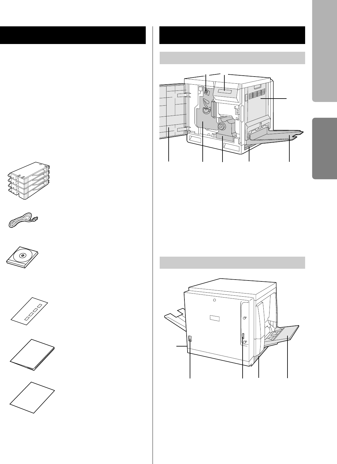
Part Names
Front side view
Rear side view
#Charge unit (see page 28)
$Printer panel
%Right side door (see page 10)
&Output tray (see page 10)
'Media tray (see page 11)
(Fuser unit
)Color imaging unit (see page 10)
*Front door (see page 10)
$
%
&'()*
#Multi-purpose tray (MPT) [see page 19]
$Left side door [Media thickness switch is
accessible by opening the left side door
(see page 19)]
%Parallel interface connector (see page 11)
&AC inlet (see page 11)
'Power switch (see page 15)
&%
$#
'
Supplement
(for model numbers of
supplies)
Before You Start
Setup Guide
#
10
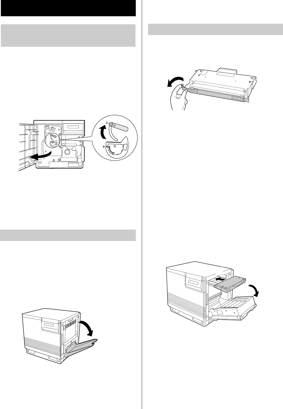
#Open the front door.
$Turn the upper green lever
clockwise until it stops and the
arrows are aligned. (This tightens
the internal belts to ready the unit
for printing.)
Close the front door.
Remove the adhesive tape and lower
the output tray.
Remove the shipping cover from the
toner cartridge.
Caution:
BTo avoid possible toner spillage, do not tilt the
toner cartridge.
Notes:
BSave all packing material for shipping purposes.
BThe toner cartridges that are shipped with the
printer are starter toner cartridges, which have
less toner. (The page life expectancy is 5,000
pages (Black)/4,000 pages (Y, M, C), which is
based on a 5% coverage of the printable area.)
#Open the right side door.
$Insert the toner cartridges in the
appropriately labeled slots.
From top to bottom, the order of the color
toner cartridges is BLACK, CYAN,
MAGENTA, YELLOW.
Caution:
BDo not leave the right side door open for more
than 1 minute; the color imaging unit will be
exposed to light and could be damaged.
Close the right side door.
2
3
Preparing the Color Imaging
Unit
1
2
Setting Up the Printer
#
$
Setting Up the Output Tray
1
1
Installing the Toner Cartridges
#
$
11
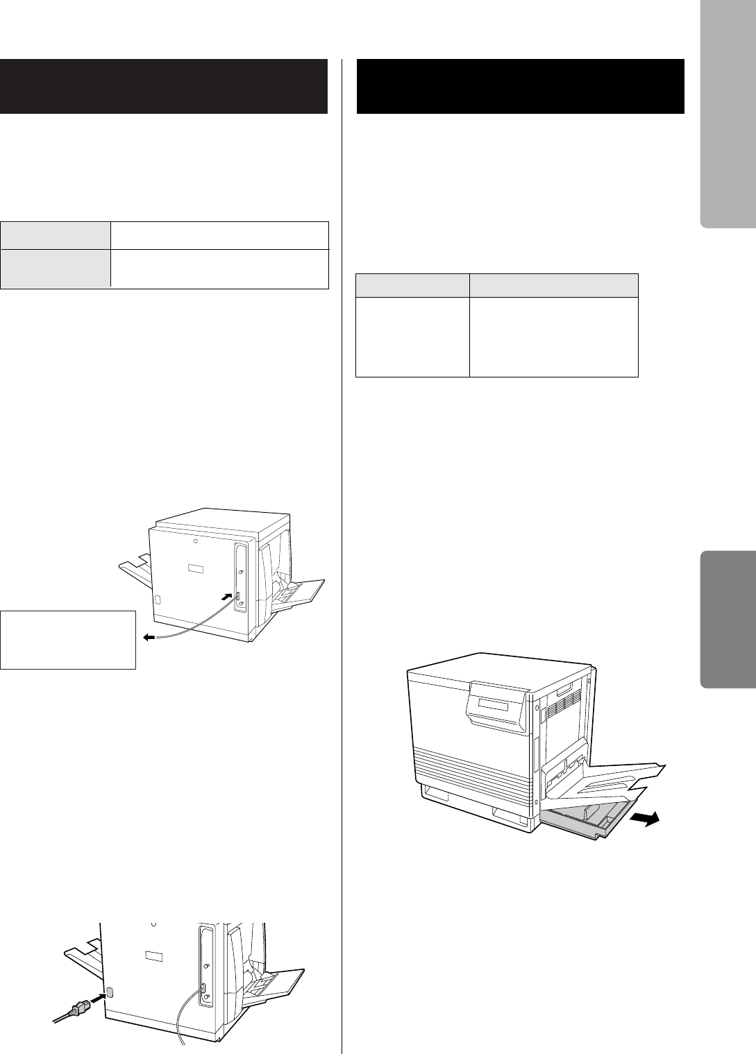
If you do not have a parallel interface cable, you will
need to purchase one (see below) from your local
computer store or dealer. For detailed information,
see page 31 in the Reference Guide.
Make sure the computer, printer and
the other connected peripheral
devices are turned off.
Connect the parallel interface cable to
the computer’s parallel interface
connector and the printer’s one.
Notes:
BThe actual connector on the computer may
differ depending on the manufacturer of the
computer.
BIf the cable is connected to the PC via a printer
buffer or selector, the printer may not print.
Connect the power cord to the
printer’s AC inlet and to an AC outlet.
The printer is shipped with a media tray (Letter
paper or A4 paper) installed. Besides them,
transparency or legal paper tray can be used.To use
these media trays, see page 18 on the Reference
Guide or “Settings and Printing” on the KX-P8415
CD-ROM.
Available media:
*1Recommended paper is as follows:
Letter/Legal: Hammermill LASERPRINT 90 g/m2
(24 lbs.)
A4: 4CC 80 g/m2
Caution:
BDo not use a media for ink jet that may be
wrapped around the fuser roller and cause
damage.
Pull the media tray out of the printer.
Remove all packing materials from
inside the media tray; refer to the
instruction sheet attached to the tray.
Connecting the Printer to a
Computer
2
3
Computer’s
parallel interface
connector
Cable
Connector Type IEEE 1284-B type connector
Use a shielded cable 2.0 m
(6.6 ft) or less in length.
1
Loading Media in the Media
Tray
1
2
Media Thickness
Laser paper*1B&W: 60 to 105 g/m2
(16 to 28 lbs.)
Color: 75 to 105 g/m2
(20 to 28 lbs.)
Setup
Setup Guide
12
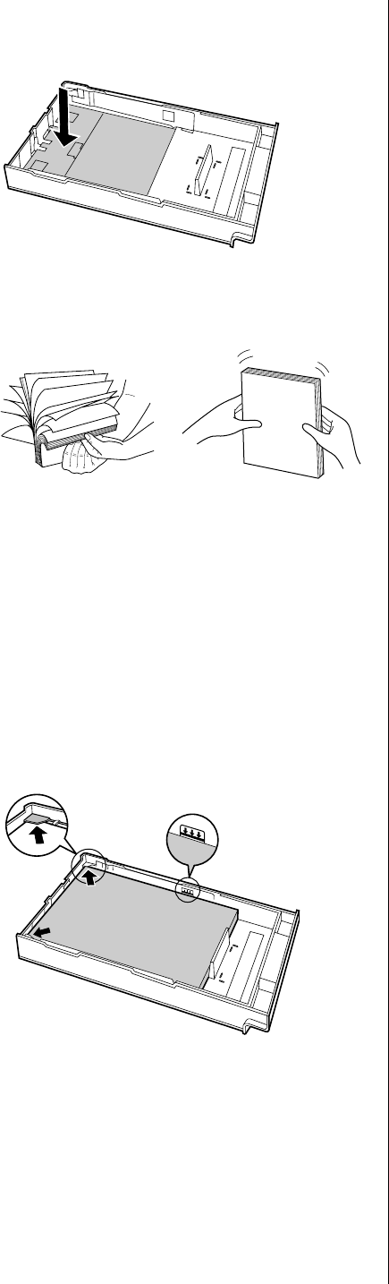
Push down on the metal plate until it
clicks, locking it in place.
Fan the paper, then tap it on a level
surface to avoid media jams or
skewed printing.
Notes:
BBe careful not to leave fingerprints on the media,
which can result in a smudged print.
BReusing media (used paper or jammed paper) that
has been fed through the printer once can reduce
the life of the consumables and paper path
components.
Place the media with the print side
down under the hooks in the tray.
The height of media should not exceed the
limit mark on the tray, or it may cause a jam.
Notes:
BMost media has instructions recommending the
side to be printed first.
B
Do not mix different types or thicknesses of media
in the media tray at one time; this may cause a jam.
Slide the media tray completely into
the slot.
Note:
BLaser paper, transparency, labels, envelope or
cardstock can be loaded on the multi-purpose
tray.
For details to use the multi-purpose tray, see
pages 18-20 of the Reference Guide.
3
4
5
6

13
When installing the KX-P8415 software, the
following can be installed.
- KX-P8415 printer driver
-
KX-P8415 Operating Instructions and this manual
- Acrobat Reader*1
To open and read the KX-P8415 Operating
Instructions manual on your screen, Acrobat
Reader program is needed.
- Tool to print the media test pattern
Note:
BWhen manually installing the Acrobat Reader
program, double-click the install program
ar40eng.exe*2under the Manual folder on the
KX-P8415 CD-ROM.
*1 It can be selectively installed.
*2File name of Acrobat Reader may differ depending
on the version.
This guide describes the instructions to install the
software when using the KX-P8415 as the local
printer.
When printing a document from a computer to the
KX-P8415 printer via network, refer to the Quick
Installation Guide provided with the optional network
card KX-PNBC8 to install the KX-P8415 software.
Start Windows 95/Windows 98.
Quit all applications.
Insert the KX-P8415 CD-ROM into
CD-ROM drive.
Double click My computer icon, then
double click the drive (example D:) for
CD-ROM.
Double click Setup.exe.
Wait until the Welcome window is displayed.
Follow the instructions on the screen
to complete the installation.
After installation, restart your system.
Start Windows NT 4.0.
Follow steps 2 through 5 for
Windows 95/Windows 98.
Click Next> .
The Choose Destination Location window is
displayed.
Click Next> .
After copying files, the Add Printer Wizard
window is displayed.
Click Next> .
Select LPT port by clicking on the
check box.
Click Next> .
Click Have Disk... .
The Install From Disk window is displayed.
Click Browse... .
Click Cancel .
The Locate File window is displayed.
For Windows 95/Windows 98
4
5
6
1
2
3
For Windows NT 4.0
4
5
1
2
3
Installing the KX-P8415
Software
6
(continued)
Setup
Setup Guide
7
8
9
10

14
Select CD-ROM drive.
Open WinNT40, English then select
Kx-p8415.inf file.
Click Open , then click OK .
Follow the instructions on the screen
to complete the installation.
After installation, restart you system.
12
13
The KX-P8415 CD-ROM includes the files for Setup
Guide and Reference Guide, Operating
Instructions, and the Acrobat Reader.
Setup Guide and Reference Guide, and Operating
Instructions are automatically installed on your
computer when installing the KX-P8415 software.
For detailed information on adjusting colors,
troubleshooting, etc., refer to the Operating
Instructions
To see the manual,
Click Start , move the pointer to
Programs, Panasonic and
Panasonic KX-P8415, then click
Operating Instructions or Setup and
Reference Guide (this manual)
.
The cover page of the manual is displayed.
To see the Operating Instructions,
read the explanation and click the
desired file name to open it.
The first page of the file will be displayed on
your computer screen.
Refer to the Help of the Acrobat Reader for
details on its operation.
Reading the Operating
Instructions on the
KX-P8415 CD-ROM
Opening a Manual’s File
2
1
11
14
15
If you need to remove the KX-P8415 software,
perform the following steps.
Click Start , move the pointer to
Programs, Panasonic and Panasonic
KX-P8415.
Click Uninstall printer driver and
utility.
Click Yes
After uninstallation, restart your
system.
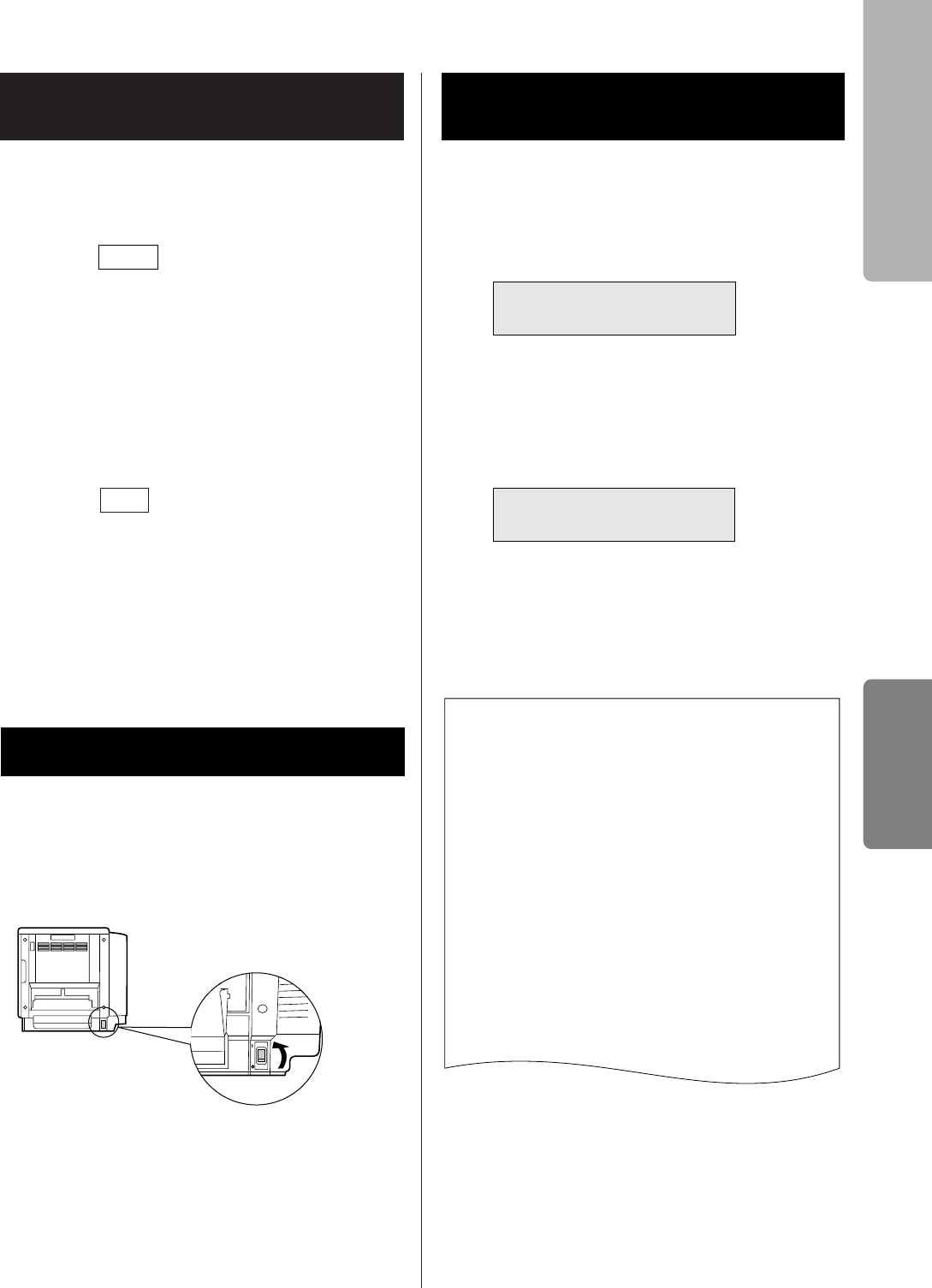
Turn the printer on, then the computer.
The Ready indicator on the printer starts blinking.
After approximately 3.5 minutes, “Ready” is
displayed on the printer LCD panel.
The LCD will darken to save energy when the printer
is idle for 30 minutes.
It is possible to confirm the printer's setting by
printing the configuration page.
Press the MENU/EXIT button to enter
the Menu Mode.
Press the H/ENTER button.
Press the ▲/CONTINUE button twice.
Press the H/ENTER button.
BThe printer will start printing a Configuration
Page.
1
2
3
Removing the KX-P8415
Software
Power On
Printing a Test Page from
the Printer Panel
1
2
3
4
Configuration Page
Printer name: Panasonic KX-P8415
Printer Information Network Information
Controller FW Version: xxxx General Information
Engine ROW Version: xx Ethernet Card Not installed
Memory size 32 MB MAC Address 00:00:00:00:00:00
Auto Duplex Unit Not installed Hardware Rev Version: 0.00
Software Rev Version: 0.00
Bias Adjustment
Offset 0 TCP/IP
CYAN 0 Protocol Disable
MAGENTA 0 DHCP Disable
YELLOW 0 IP Address 0. 0. 0. 0
BLACK 0 Subnet Mask 0. 0. 0. 0
Gateway 0. 0. 0. 0
Maintenance Banner Page Disable
Page Count
Color 0 Netware
Monochrome 0 Protocol Disable
Toner Cartridge
CYAN XX % remaining Polling Internet 0 seconds
MAGENTA XX % remaining Bindery Enable
YELLOW XX % remaining
BLACK XX % remaining NDS
Imaging Unit XX % remaining Tree
Charge Unit XX % remaining
Transfer Unit XX % remaining
Fuser Unit XX % remaining Context
Oil Roll XX % remaining
Cleaning pad XX % remaining
Imaging Area
Last
CYAN 0 %
MAGENTA 0 % Adjustment to Media
YELLOW 0 % Plain Paper 0
BLACK 0 % Transparency 0
Average Label 0
CYAN 0 % Coated Paper 0
Envelope 0
Card 0
Frame Types Auto
Menu Mode
Test Page
Test Page
Configuration Page
Setup
Setup Guide
4

16
FOR USERS IN UNITED STATES
This equipment has been tested and found to comply with the limits for a Class B digital device, pursuant
to Part 15 of the FCC Rules. These limits are designed to provide reasonable protection against harmful
interference in a residential installation.
This equipment generates, uses, and can radiate radio frequency energy and, if not installed and used in
accordance with the instructions, may cause harmful interference to radio communications.
However, there is no guarantee that interference will not occur in a particular installation. If this
equipment does cause harmful interference to radio or television reception, which can be determined by
turning the equipment off and on, the user is encouraged to try to correct the interference by one or
more of the following measures:
BReorient or relocate the receiving antenna.
BIncrease the separation between the equipment and receiver.
BConnect the equipment into an outlet on a circuit different from that to which the receiver is connected.
BConsult the dealer or an experienced radio/TV technician for help.
The user may find the booklet “Something About Interference” available from FCC local regional offices
helpful.
FCC Warning: To assure continued FCC emission limit compliance, the user must use the
recommended shielded interfacing cable when connecting to a host computer. Also, any unauthorized
changes or modifications to this equipment would void the user’s authority to operate this device.
Technical Support Calls
If you have read this manual and tried the troubleshooting procedures and you are still having difficulty,
please contact the reseller from which the unit was purchased. You may also call the end user technical
support telephone number which is operational during East Coast business hours (9:00 AM to 7:00 PM).
The end user technical support number is 1-888-744-2424.
This number is available within the U.S. only.
Helpful Phone Numbers
To locate your nearest sales dealer CALL 1-800-742-8086 ask for COLOR
To order consumables CALL 1-800-222-0584
To order operating instructions/CD’s CALL 1-800-833-9626
To locate your nearest authorized service center CALL 1-888-744-2424
For technical support CALL 1-888-744-2424
Automated 24-hour support via Fax back CALL 1-800-222-0584
Electronic bulletin board CALL 1-201-863-7845
World Wide Web Technical & Driver Support http://www.panasonic.com/alive
■When the optional Network Interface Card (NIC) has been installed to this printer and connected to a
Network cable, the printer meets the requirements of FCC Class A.

17
About Media . . . . . . . . . . . . . . . . . . . . . . . . . . .18
In the Media Tray . . . . . . . . . . . . . . . . . . . . . . .18
On the Multi-purpose Tray . . . . . . . . . . . . . . . .19
Printing on Transparency, Label or
Envelope . . . . . . . . . . . . . . . . . . . . . . . . . . . .20
Automatic Duplex Printing . . . . . . . . . . . . . . .20
Using the Printer Panel . . . . . . . . . . . . . . . . . .20
Adjusting the Color Density . . . . . . . . . . . . . .21
Cleaning the Printer . . . . . . . . . . . . . . . . . . . . .22
Clearing Media Jams . . . . . . . . . . . . . . . . . . . .22
Troubleshooting . . . . . . . . . . . . . . . . . . . . . . . .25
Error Messages . . . . . . . . . . . . . . . . . . . . . . . .28
Printer Components . . . . . . . . . . . . . . . . . . . . .28
Specifications . . . . . . . . . . . . . . . . . . . . . . . . . .30
Options and Supplies . . . . . . . . . . . .back cover
Contents
Reference Guide
Loading Media
Settings and Printing
Maintenance
Appendix
Loading Media Settings and
Printing Maintenance Appendix
Reference Guide
This Reference Guide describes the instructions in outline.
For the detailed information, refer to the Operating Instructions installed on your
computer.
Transparency
Paper
18
Caution:
BDo not use a media for ink jet that may be
wrapped around the fuser roller and cause
damage.
Available media tray:
A4 Paper
A4 Transparency
Letter Paper
Letter Transparency
Legal Paper
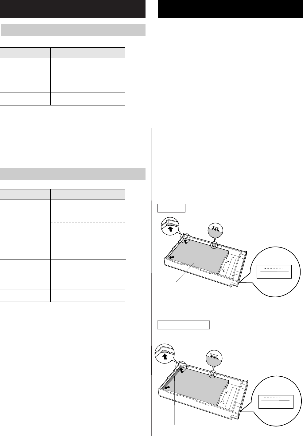
Push down on the metal plate until it clicks,
locking it in place.
Place the media with the print side down
under the hooks in the tray.
BThe height of media should not exceed the
limit mark on the tray, or it may cause a jam.
*1Recommended paper is as follows:
Letter/Legal: Hammermill LASERPRINT 90 g/m2
(24 lbs.)
A4: 4CC 80 g/m2
*1When you perform the manual duplex printing,
you should not expect the same print quality and
reliability that you get with single-sided printing.
See the notes on page 30.
*2The print quality may not be stable. Use the
media tray for best reliability.
For the notes and detailed media specification, refer
to “Specifications” of the Operating Instructions
installed on your computer.
About Media
Media Tray
Media Description
Laser paper*1
Transparency
B&W: 60 to 105 g/m2
(16 to 28 lbs.)
Color: 75 to 105 g/m2
(20 to 28 lbs.)
3M CG3710
Media Description
Laser paper
Transparency*2
Single-sided printing:
75 to 165 g/m2
(20 to 44 lbs.)
Manual duplex printing*1:
75 to 165 g/m2
(20 to 44 lbs.)
3M CG3710
Labels Avery 5163-5165,
L7163, L7165-L7169
Envelope #10 [Black text only]
Cardstock Up to 165 g/m2
In the Media Tray
1
2
Print side down
3M CG3710:Leading tape side up
Paper
Transparency
Multi-purpose Tray
19
Caution:
BDo not use a media for ink jet that may be
wrapped around the fuser roller and cause
damage.
■Setting media thickness switch
Because of the most reliable paper-picking for
various media weights, media thickness can be
manually selected.
Open the left side door.
Move the switch to the desired setting.
■Loading Media
Available media size: 91 mm x 254 mm to
216 mm x 356 mm (3.6″x 10″to 8.5″x 14″).
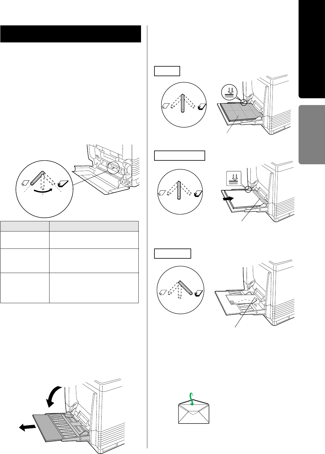
#Open the multi-purpose tray.
$Extend the media support.
Insert the media with the printing side up into
the multi-purpose tray.
BThe height of media should not exceed the
limit mark on the tray, or it may cause a jam.
Note:
BWhen a wrinkle occurs, try printing with the
flap inserted in the envelope as shown in figure.
Switch setting Media
Thin (Default)
Middle
Laser paper 75 to 90 g/m2
(20 to 24 lbs.)
Laser paper 91 to 123 g/m2
(25 to 32 lbs.)
Label, Transparency, Coated paper
Thick Laser paper 124 to 165 g/m2
(33 to 44 lbs.)
Envelope #10
Card stock up to 165 g/m2
Thin Middle Thick
1
2
1
2
Taped side facing down
(3M CG3710)
Transparency
Label
Envelope
Short-end
Print side up
Print side up
Loading Media
Reference Guide
On the Multi-purpose Tray
#
$
20
It is possible to see the following menus to configure
the printer by printing the menu map.
BTest page, Bias Adjustment, Maintenance, Image
Area, Power Saver, Network Protocol Setup*1,
Adjustment to Media, Language.
*1This menu wil not appear if the network card is not
installed in the printer.
To print the menu map,
Press the MENU/EXIT button on the printer
panel.
Press the FF/CONTINUE or GG/CANCEL
button until the Menu Map is displayed. Press
the HH/ENTER button.
The menu map will be printed.
To perform the setting:
Press the MENU/EXIT button to enter the
menu mode.
Set the printer using the following buttons.
Press the MENU/EXIT button to exit the menu
mode.
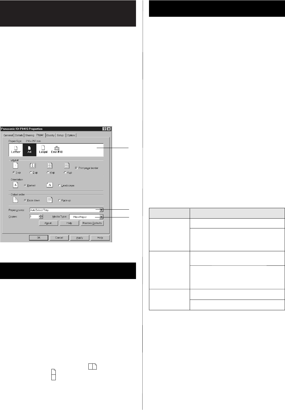
Display the print window in the application
software.
Select Panasonic KX-P8415 printer and click
Properties.
Click Paper tab.
Select paper size (#), paper source ($) and
media type (%).
BIf transparency tray is used, select
AutoSelect Tray of Paper source.
BIf media is loaded on the multi-purpose tray,
select Multi-purpose Tray of Paper source.
Installing the 2nd cassette feeder with ADU option
enables automatic duplex printing .
Be sure that the Duplex Unit must be added to the
Installed Options on the Option tab in the printer
driver before automatic duplex printing is possible.
Display the print window in the application
software and click Properties.
Display the Setup tab of the Panasonic
KX-P8415 Properties window.
Enable Flip on long edge ( ) or Flip on
short edge ( ).
For the detailed information, refer to the “Settings
and Printing” of the Operating Instructions installed
on your computer.
Printing on Transparency,
Label or Envelope
2
3
4
1
$
#
%
3
1
1
2
2
3
AA
A
A
1
2
Button Operation
Display the next menu or item
G/CANCEL
Increase the numerical value of
the selection by 1 or display the
next selection
F/CONTINUE
Display the previous menu or
item
Decrease the numerical value of
the selection by 1 or display the
previous selection
Enter a sub-menu
Activate a selection
H/ENTER
Using the Printer Panel
Automatic Duplex Printing
21
This feature compensates for the changes in density
that can occur as environmental conditions change,
toner cartridges or the color imaging unit age.
To adjust the density, print a color calibration page
and adjust the color density.
For the detailed information with color images, see
the “Settings and Printing” of the Operating
Instructions installed on your computer.
Press the MENU/EXIT button to enter the
menu mode.
Display the Bias Adjustment menu by
pressing the FF/CONTINUE and the
HH/ENTER button.
Display the Calibration Test menu by pressing
the FF/CONTINUE button 5 times and the
H/ENTER button.
A Color Calibration Page will be printed.
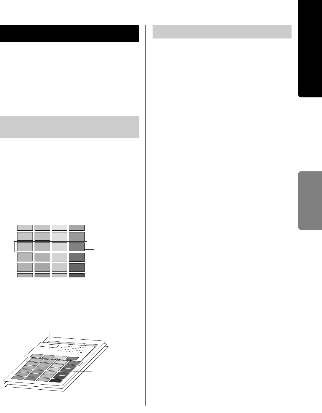
Compare the current color density settings on
the Color Calibration Page with the color
density samples on the Color Calibration Card
to see if they match.
Determine which each block on the Color
Calibration Page most closely matches the
density of the each color sample on the Color
Calibration Card.
Enter the menu mode and display the Bias
Adjustment menu.
Press the HH/ENTER button. Select the
desired menu.
Calibration Offset menu: adjusts the density
for all colors simultaneously.
CYAN, MAGENTA, YELLOW or BLACK
menu: adjusts each color.
Press the HH/ENTER button.
Press the FF/CONTINUE or GG/CANCEL
button to darken/lighten all the colors.
The color density will be changed by 1 level
by pressing each button 2 times.
Press the HH/ENTER button to reprint the
Color Calibration Page.
Compare it with the Color Calibration Card to
confirm the setting.
Adjusting the Color Density
2
3
4
1
Current color
density settings
5
Color Calibration Card
Color Calibration
Page
Adjusting the Color Density
2
3
4
1
5
6
Printing a Color Calibration
Page
Settings and
Printing
Reference Guide
22
Periodic cleaning of the printer is recommended.
The frequency of cleaning is dependent upon the
environment in which the printer is used. You should
clean the printer:
BAt least once a month.
BWhen the printer experiences frequent media
jams.
BWhen print quality has deteriorated.
For the detailed information, refer to “Care and
Maintenance” of the Operating Instructions installed
on your computer.
■Jam at B, C, G, H:
To clear a jam, see the instructions on this
Reference Guide and “Care and Maintenance” of the
Operating Instructions installed on your computer.
■Jam at A, D, E, F, MPT:
To clear a jam, refer to the label inside the front door
and “Care and Maintenance” of the Operating
Instructions installed on your computer.
■
Incorrect media or wrong media settings
When “Media type mismatch” appears on the
printer panel, remove the jammed media [ see
instruction above in “Jam at A” or “Jam at MPT
(multi-purpose tray)”], then load the media in the
correct media tray or select the correct media in the
printer driver (see “Settings and Printing” of the
Operating Instructions installed on your computer).
Note:
BIf the error message is not cleared after removing
jammed media, open and close the front door to
clear it.
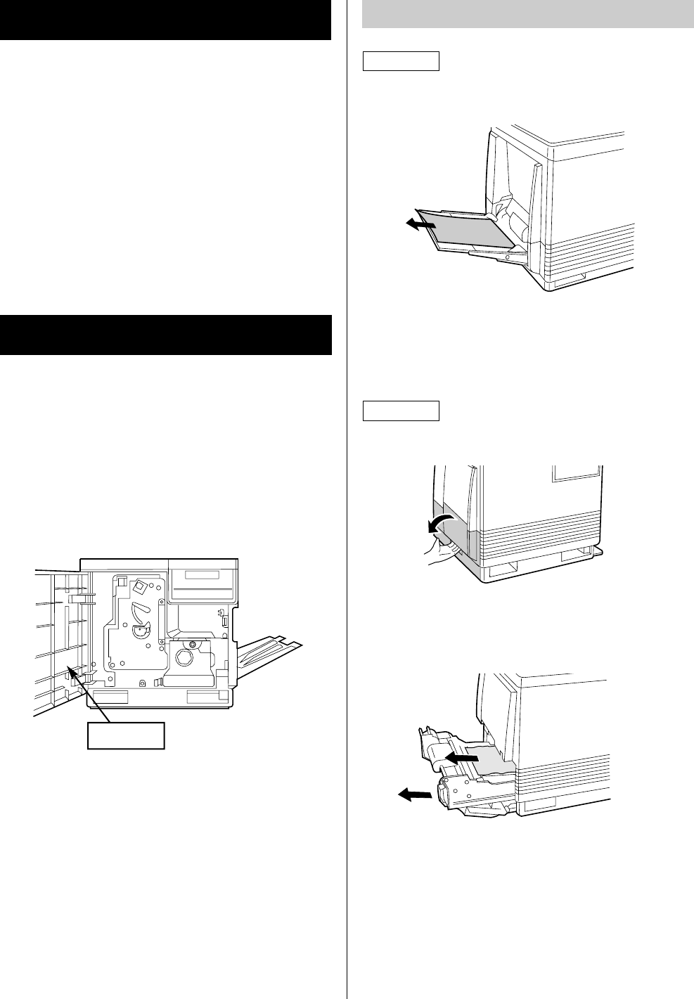
Remove the jammed media from the multi-
purpose tray.
Open and close the front door to clear the
error message.
Open the left side door.
Pull out the paper feeder using the green
handles. Remove the jammed media on or
under the paper feeder.
Insert the paper feeder and close the left side
door.
Clearing Media Jams
Label
2
Method A
Method B
2
1
1
3
Jam at B (Method A or B)
Cleaning the Printer
23
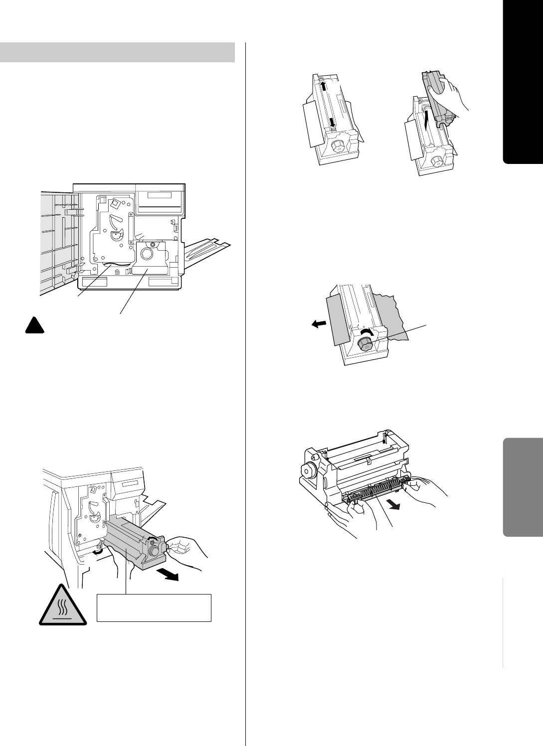
Open the front door and check whether the
media is jammed under the color imaging unit.
If the media jam is not found, go to next step.
BIf the media is jammed, remove it by
following Method B of Jam at B.
To clear error message “Jam at C”, slide out
the fuser unit, then slide it back to the printer.
#Turn the green thumbscrew
counterclockwise.
$Holding the green tab, slide the fuser unit
out until it stops.
%Press the green lever.
Hold the fuser unit (see above) and slide it out
and close the front door.
SAFETY CAUTION:
BThe fuser unit weighs approximately 3.1 kg
{6.8 lbs.}. Take care when handling it.
Press out on tabs to unlock and remove the oil
supply roll out of the fuser unit.
Note:
BIf the paper is not jammed in the fuser unit,
perform Method B of Jam at B on page 22.
#Turn the fuser unit’s green knob clockwise.
$Remove the jammed media.
Note:
BIf needed, you can remove the cleaning pad to
remove the jammed media.
SAFETY CAUTION:
BDo not touch the roller and the parts around the
roller when handling the fuser unit, because they
may be hot.
3
2
Jam at C
SAFETY CAUTION:
The fuser unit is hot; to avoid personal
injury, turn off the printer and wait 10
minutes (after opening the front door) for
the fuser unit to cool before touching it.
!
Jammed media
1
#
%
CAUTION:
HOT SURFACE INSIDE
5
4
#
$
#
Cleaning pad
Green Knob
$
#
$
(continued)
Maintenance
Reference Guide
24
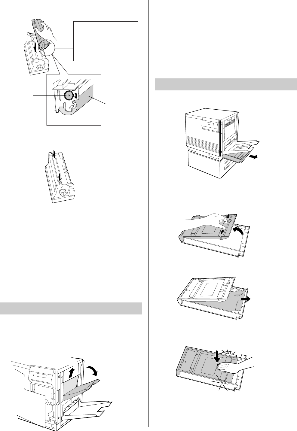
Replace the oil supply roll into the fuser unit.
Press down firmly on the oil supply roll to snap
both sides into place.
Open the front door and slide the fuser unit
back into the printer (Refer to the illustration
on step 2).
Turn the small green thumbscrew clockwise to
lock the fuser unit.
Close the front door.
Note:
•The error message “Jam at C” is cleared by sliding
out the fuser unit, then sliding it back to the printer.
#Open the access door (above the plastic
output tray).
$Remove the jammed media.
Open and close the front door to clear the
error message from the LCD.
OR
Perform steps 1 through 5 of Jam at G, H
(see below).
Remove the auto duplex printing unit.
Open the lid of auto duplex printing unit while
squeezing the green knobs.
Remove the jammed paper.
Close the lid and press down firmly on it to
snap both sides into place.
Reinsert the auto duplex printing unit.
6
Oiled cloth
If the oiled cloth is
loose, rotate the gear
(A) clockwise until it is
tight. Do not touch the
oiled cloth.
(A)
7
8
9
1
#
$
Jam at F
2
1
Jam at G, H
1
2
3
4
5
25
■Printing a Test Print
Executing Test Print enables you to print the color
halftone pages (Cyan, Magenta, Yellow and Black)
to check the print quality.
1. Press the MENU/EXIT button on the printer
panel.
2. Press the HH/ENTER button.
3. Press the FF/CONTINUE button twice.
The Test Print menu will appear.
4. Press the HH/ENTER button to print each color
page.
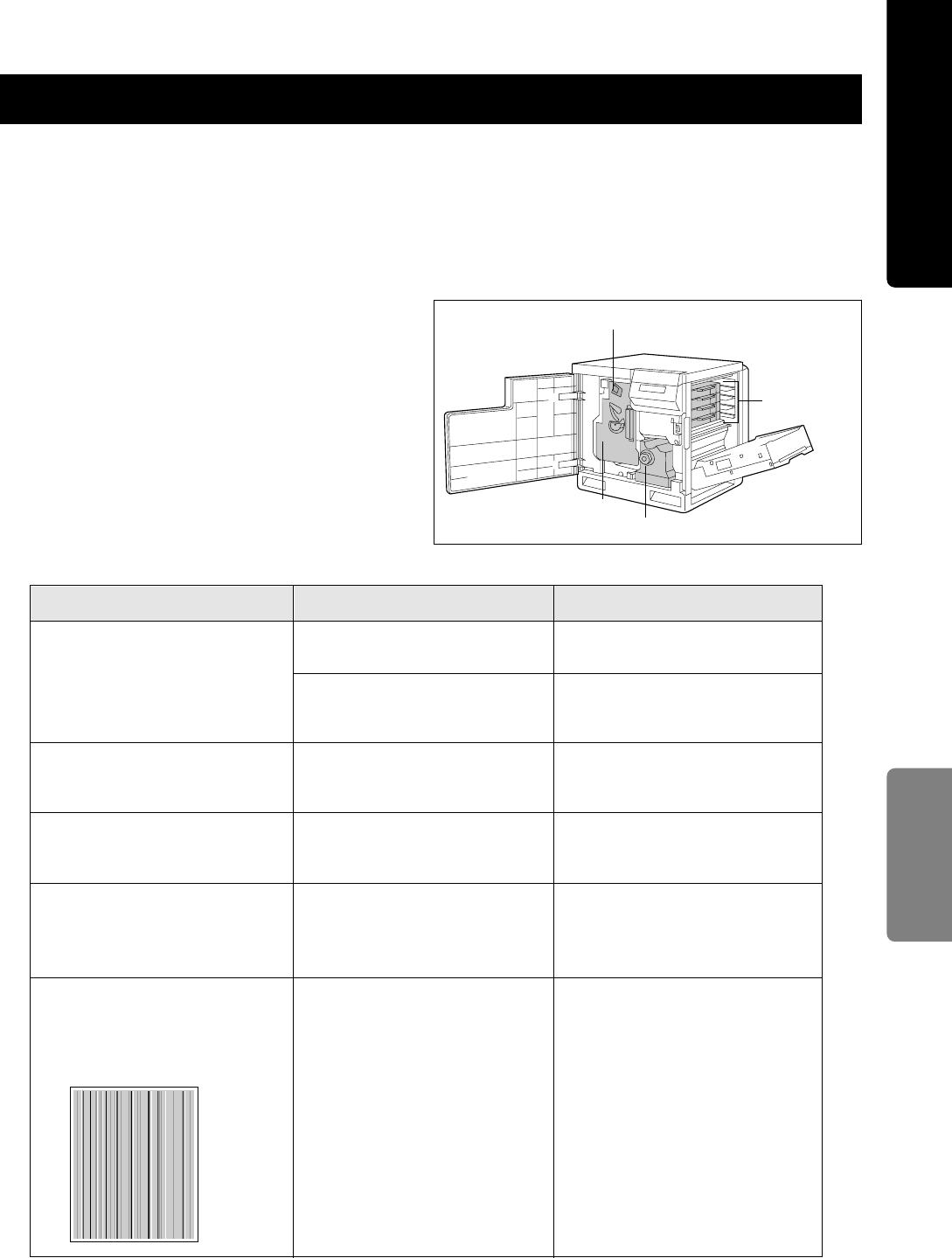
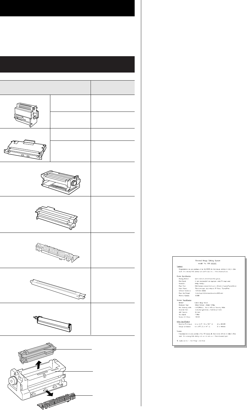
■Replacing Printer Components
(see page 28)
It may need to replace the following components to
solve the trouble.
Troubleshooting
For the detailed information, refer to “Care and Maintenance” of the Operating Instructions installed on your
computer.
READY indicator is blinking.
The toner is almost depleted.
Read the printer panel message to
determine the printer status.
Corrective Action
Trouble
ERROR indicator is blinking.
Wait for the job to be completed or
cancel the job.
The printer is receiving,
processing or printing job.
Possible Cause
Exit the Menu mode by pressing
the MENU/EXIT button.
Correct the condition displayed on
the printer panel (e.g., close the
door or clear the media jam).
Turn the printer off and back on
again. If the indicator is still on, the
printer requires service.
You have entered the Menu
mode in the printer panel.
The printer is not ready, is
disabled, or has detected an
error.
The printer has stopped because
it detected a user-correctable
error such as an open door or a
media jam.
Error occurred that is not user-
correctable.
READY indicator is off.
ERROR indicator is on.
Replace the color toner cartridge.
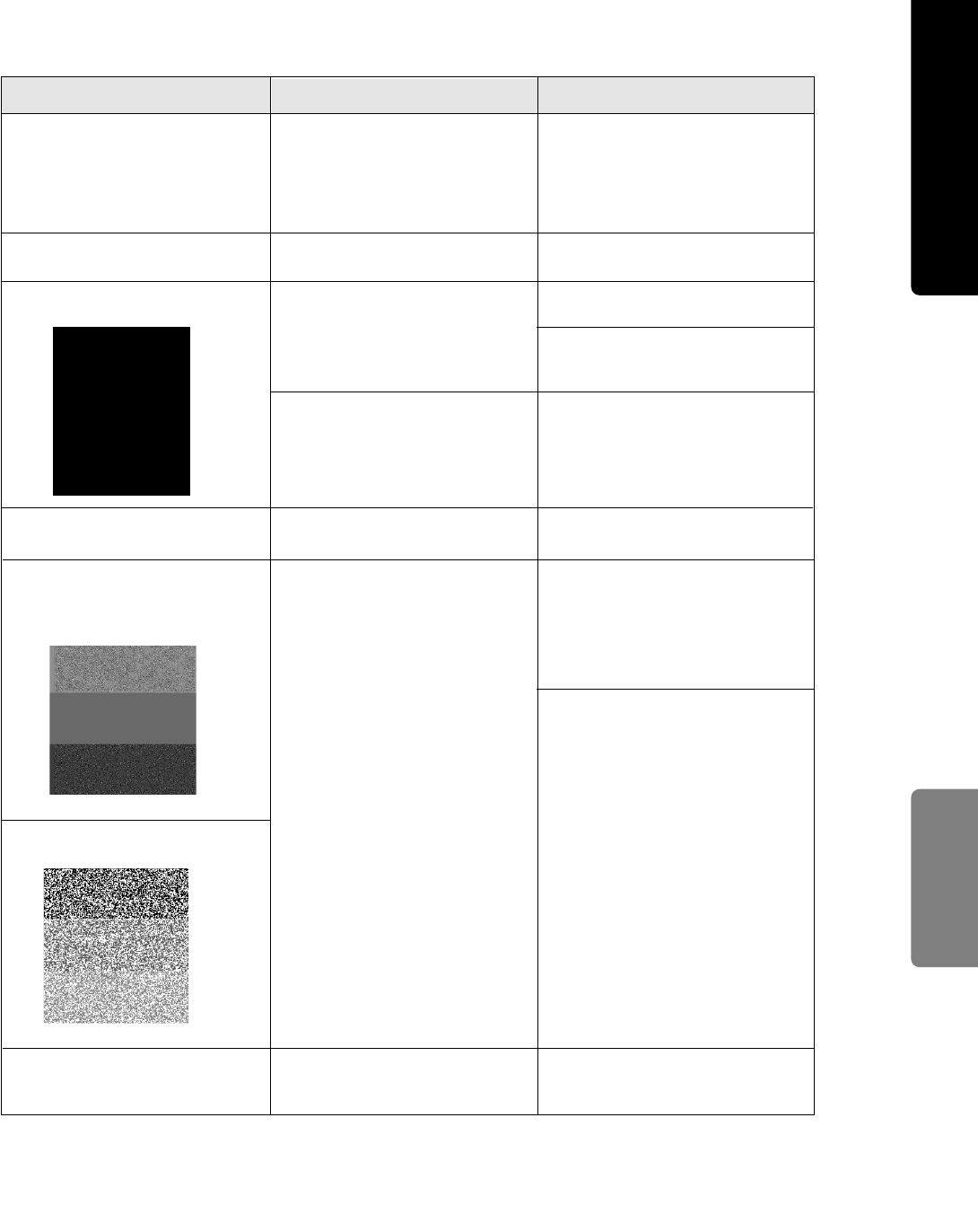
On the Test Print, a single color is
not uniform or many vertical
streaks (both light and dark) of
slightly different density and non-
uniform color.
Charge unit
Toner
cartridges
Color imaging unit Fuser unit
Maintenance
Reference Guide
26
Corrective Action
Trouble Possible Cause
Store media in the original, dust-
free package in the same
environmental conditions as the
printer.
Paper doesn’t match the
environmental conditions, or it
has too much moisture.
Try fresh paper, or another type of
paper.
On the Test Print, halftone area
has areas of weak color.
The toner cartridge is almost
depleted and is not properly
applying toner.
Replace the color toner cartridge.
The toner is almost depleted.
On the Test Print, a single color has
a sharp, dark or light vertical streak.
Replace the color toner cartridge soon
The color density is set
incorrectly in the printer panel.
A single color appears faded.
Adjust the color density (see page 21)
The photosensitive belt inside the
color imaging unit is scratched. Replace the color imaging unit.On the Test Print, straight, thin
light vertical line in colors.
Replace the color imaging unit.
The color imaging unit is damaged.
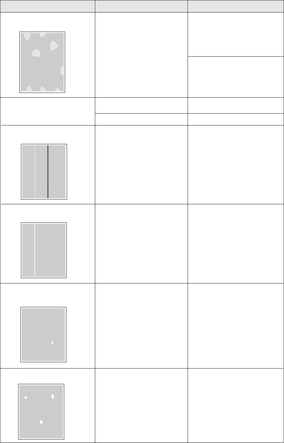
On the Test Print, a single white
spot appears in approximately the
same vertical place on the page.
Fingerprint(s) on the underside
belt or photosensitive belt
(inside) of the color imaging unit.
Print several pages until the spots
fade.
On the Test Print, large light
spot(s) appear randomly.
27
Corrective Action
Trouble Possible Cause
Print 5-10 pages of blank pages to
clean the roller.
If you still see the problem:
BReplace the oil supply roll.
If you still see the problem:
BReplace the fuser unit.
A piece of the printed image is
missing and reappears out of
place, approximately 129 mm (5″)
down the page.
The fuser unit’s internal roller is
not being consistently oiled.
or
The fuser unit’s internal roller is
contaminated with toner
particles.
Replace the oil supply roll.
The oil supply roll has reached
the end of its useful life.
Media frequently wraps around
the fuser unit.
Reinsert the color imaging unit to
correct the contact for the charge
unit.
The entire page prints in black,
including the borders. Bad electrical contact for the
Charge unit.
The charge unit is broken.
The cleaning pad may get dirty
with toner. Replace the cleaning pad.
The back of the printed page
appears dirty.
Remove and reinsert the charge
unit.
Replace the charge unit.
Solid color print for green, red and
blue are not printed out evenly in
the Adjustment to Media test
pattern.
Unrecommended media is used. Adjust the Adjustment to Media
value using the Printer panel. (See
“Adjusting the Adjustment to Media
Setting” in the “Settings and
Printing” installed on your
computer).
*1
Use the recommended media
(see page 18).
Black, magenta and cyan halftone
have weak color area.
*1
Service Error is displayed on the
LCD. An error occurred that is not user-
correctable. Turn the printer off and back on
again. If the error persists, call for
service.
*1To see the sample in full color, see “Care and Maintenance” of the Operating Instructions installed on your
computer.
Maintenance
Reference Guide
28
*1Average life is based on an average of 5%
coverage of the printable area and standard
density for any one color (refer to Example A:
Monochrome 5% coverage). For the components
below, the average life may decrease depending
on the percentage of colors and coverage used.
For the detailed information of color imaging unit,
fuser unit and cleaning pad, see page 29.
BColor imaging unit
BFuser unit
BToner cartridge
BCleaning pad
*2If you print with high density when “Low <Color>
Toner” is displayed, you may get faded printout
before “<Color> Toner Empty” is displayed.
*3Specialty media (Transparencies, coated paper,
etc.) will result in shortening the life of each
consumable. When one page is printed on this
type of media, 2 pages are counted.
Do not insert the used oil supply roll into the new
fuser unit; it may damage the new fuser unit.
*4Using media except the recommended media
(see page 18) will result in shortening the life of
consumable.
*5When you have just replaced the transfer unit or
cleaning pad, you must reset the counter to 100%
remaining (see the each supply's manual).
Printer Components
Average LifePrinter Components
60,000 pages
Monochrome
15,000 pages
Color
12,000 pages
Black
10,000 pages
Cyan,
Magenta,
Yellow
Toner cartridges
*1*2
60,000 pages
*3 *4
Fuser unit *1
Oil supply roll (with cleaning pad)
Transfer unit *5
15,000 pages *3
80,000 pages
30,000 pages
15,000 pages
*4
Charge unit
Cleaning pad *1 *5
Example A
Color imaging unit *1
Error Messages
For the detailed information on error messages,
refer to “Care and Maintenance” of the Operating
Instructions installed on your computer.
Oil supply roll
Fuser unit
Cleaning pad
Note when performing duplex printing:
Duplex printing will result in shortening the life of
fuser unit. When one sheet is printed, 2 pages are
counted per one side.
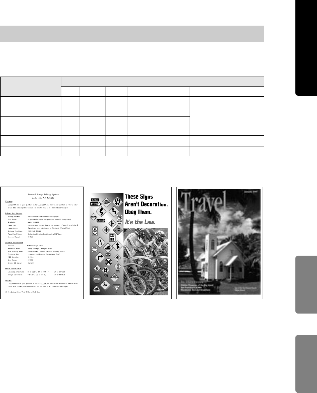
29
The average life of printer components (color imaging unit, fuser unit and cleaning pad) varies
depending on the percentage of colors and coverage used. When printing at full color with high
percentage of coverage, the average life of these components will be decreased.
Average Life of Printer Components
Print pattern
Coverage of the printable area (%)
Monochrome 5%
coverage (Example A)
Cyan Magenta Yellow Black
Life (pages)
Color imaging unit Fuser unit Cleaning pad
15,000
60,00060,0005000
5555
10101010
3119104
Full color 5% coverage
Full color 10% coverage
Full color (Example B)
17292232Full color (Example C)
15,000
7,500
4,688
3,000
30,000
18,750
12,000
7,500
4,688
3,000
Example A Example B Example C
For a reference to these examples in full color, see “Care and Maintenance” of the Operating
Instructions installed on your computer.
Note:
BEach file’s coverage is measured by pixel counter on letter size. The coverage will differ depending
on printers.
Maintenance Appendix
Reference Guide
30
■Media sizes/Margins and print
area
Refer to “Specifications” of the Operating
Instructions installed on your computer.
■Types of Paper to avoid
BExtremely smooth or shiny paper or paper that is
highly textured
BLetterhead imprinted with low temperature or
thermography. These materials may transfer onto
the fusing roller and cause damage. Any pre-
printed paper should use inks compatible with
200°C (392°F) for 0.1 second.
BDamaged or wrinkled paper, or paper with
irregularities such as tabs, staples, etc.
BMultipart forms or carbonless paper
BPaper with a 25% or more cotton and/or fiber
content
BInk jet media (paper, transparency,etc.)
(It may transfer onto the fuser unit roller and cause
damage.)
■Duplex printing
Manual duplex printing is possible by using the multi-
purpose tray. Automatic duplex printing is possible
by installing the optional 2nd cassette feeder with
ADU. However, you should not expect the same
print quality and reliability that you get with single-
sided printing. We strongly recommend that you
follow the guidelines below.
Notes for manual duplex printing:
BDo not load more than 50 sheets in the multi-
purpose tray.
BBefore loading paper in the multi-purpose tray,
adjust it so that the edges of the media are lightly
touching the media guides of the multi-purpose
tray.
BUse multi-purpose tray for second side printing.
Specifications
For detailed information on specifications, refer to
“Specifications” of the Operating Instructions
installed on your computer.
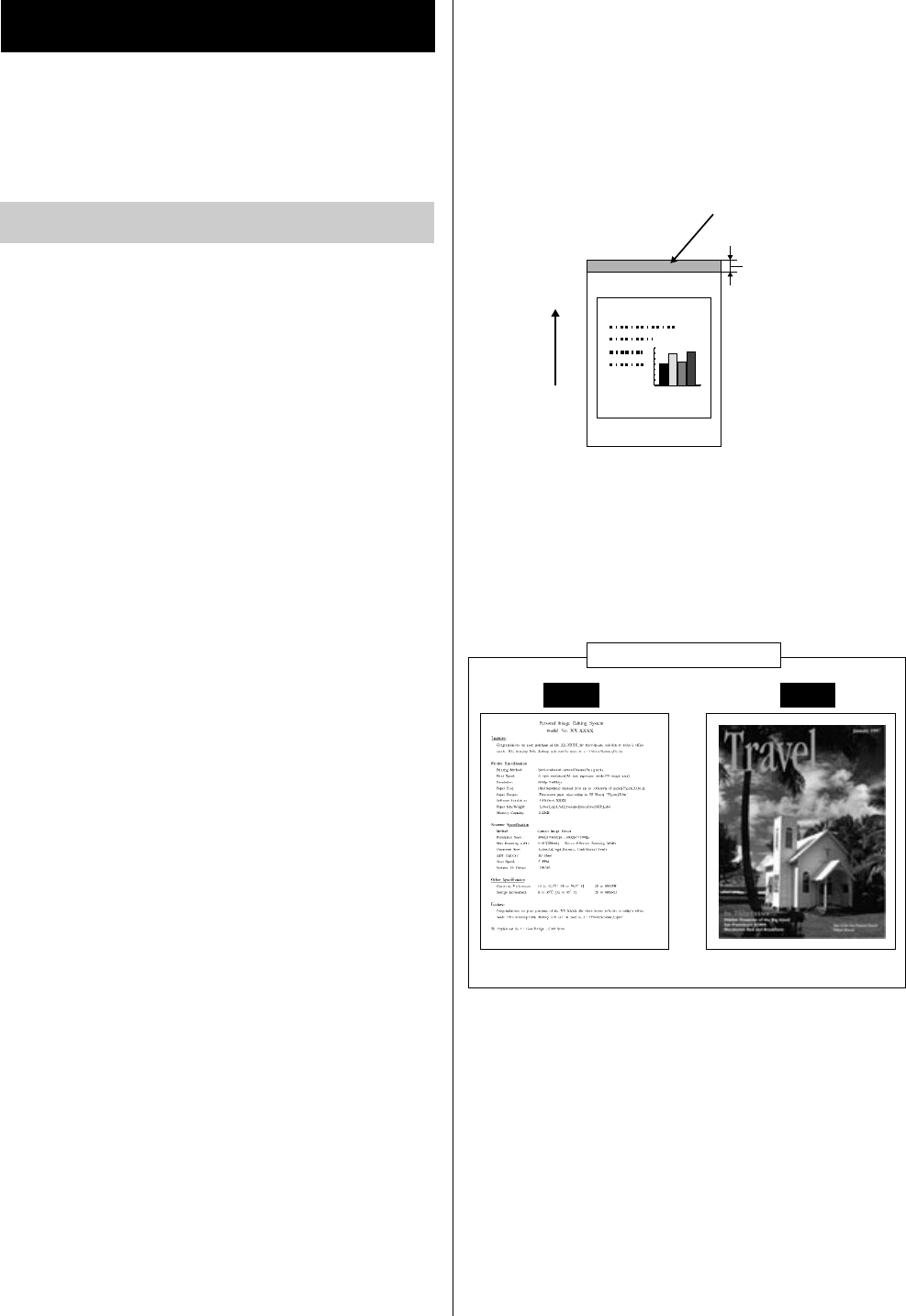
Notes for manual / automatic duplex printing:
BIt is strongly suggested to use color laser bond
paper.
BBefore printing on the first side, set the unprintable
area [at least 15 mm (0.59″) in length] on the top
of paper (see below.)
BWhen printing on the first side, avoid printing
photograph or graphic in solid color to prevent
paper jamming. It may cause a damage to the
printer.
Unprintable area
[a : at least 15 mm (0.59")]
Paper feed
direction
Pollution of World
a
It is strongly
recommended that
the sizes of
photograph and
graphic printed on
the page are as
small as possible.
The first side printing
OK N.G.
Ex. Characters
Ex. Photograph in solid color
Media
31
The bidirectional parallel interface is based on the
IEEE P1284-B standard.
If your computer has a bidirectional parallel port, the
printer driver and printer can take advantage of
faster data transfer.
Specifications
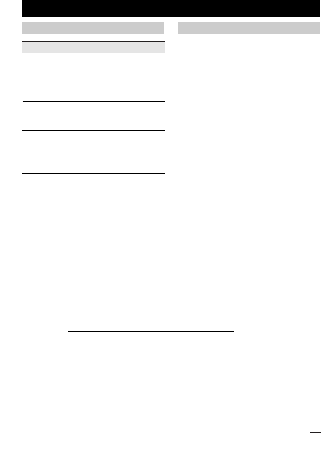
Pin configuration
Parallel Interface connector (printer side)
Note:
B“Return” denotes the return side wire of a twisted
pair cable and is connected to signal ground.
BBe sure to use only a shielded cable. The printer
will not operate properly if any of the pins is not
connected.
■Transparencies and labels
Panasonic has tested and found that the following
work satisfactorily:
OHP transparency: 3M CG3710
Labels: AVERY 5163, AVERY 5164, AVERY 5165,
Avery L7163, Avery L7165, Avery L7166, Avery
L7167, Avery L7168, Avery L7169
BRe-using transparencies that have been fed
through the printer once (for example, after jams
or if the transparency is ejected without being
printed) can reduce the life of the consumables
and paper path components.
BWith any label stock, the labels must completely
cover the backing material.
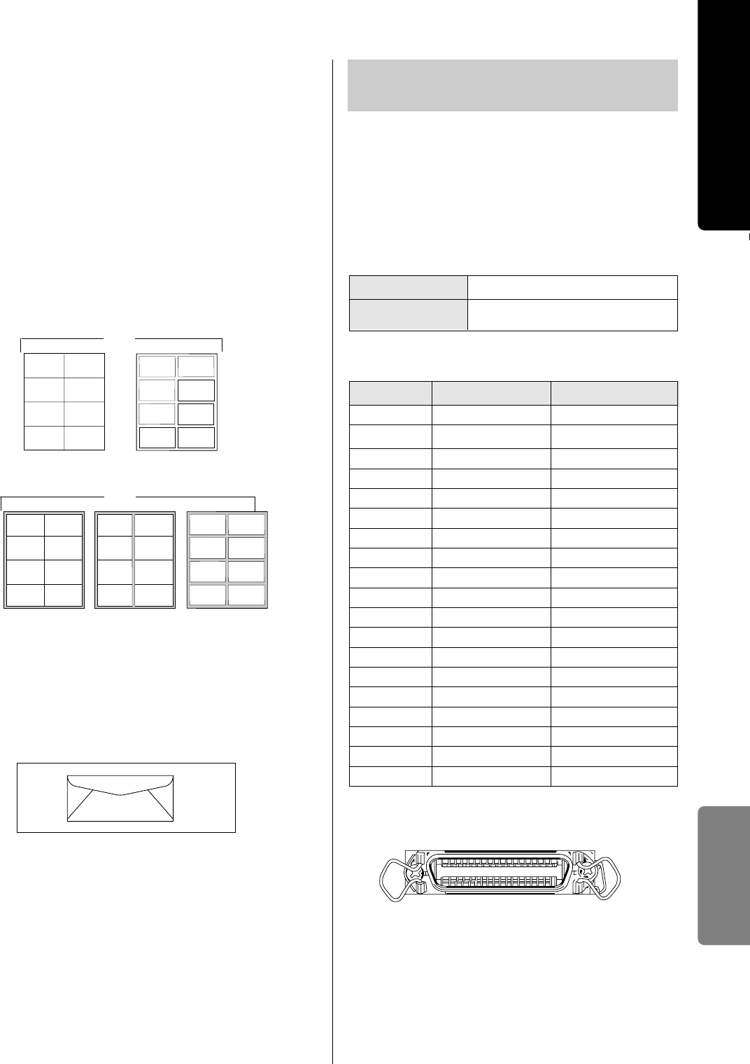
■Envelopes
It is recommended that you print in black text only
and purchase high quality #10 laser envelopes with
diagonal seams, as shown in the diagram below:
High quality envelopes have the following
characteristics:
BA thin, sharply creased leading edge
BPaper weight of 90 g/m2(24 lbs.)
BFlat, free of curls, wrinkles, nicks, etc.
Note:
BWrinkle may occur in some case, even if high
quality envelopes are used.
NO
The backing material is exposed.
Labels cover the entire backing material.
YES
18
36
1
19
IEEE 1284-B type connector
Cable Use a shielded cable 2 m
(6.6 ft.) or less in length.
Connector Type
Bidirectional Parallel
Interface
Signal
+5V(Peripheral)
nSelectin
Return side pin
30
19 Busy
Signal Pin
1
20 Select2
21 nAck3
22 nFault4
23 PError5
24 Data 16
25 Data 27
26 Data 38
27 Data 49
28 Data 510
29 Data 611
Data 712
31 Data 813
32 nInit14
33 nStrobe15
3416
35 nAutoFd17
+5V(Host)18
36
Appendix
Reference Guide
Panasonic Document Imaging Company,
Division of Matsushita Electric Corporation of America,
Two Panasonic Way, Secaucus, New Jersey 07094
Panasonic Sales Company (PSC)
Division of Matsushita Electric of Puerto Rico, Inc.
Ave. 65 de Infatería, Km. 9.5, San Gabriel Industrial Park
Carolina, Puerto Rico 00985
Panasonic Canada Inc.
5770 Ambler Drive, Mississauga, Ontario, L4W 2T3
http://www.panasonic.ca
Matsushita Electric Industrial Co., Ltd.
Central P.O.Box 288, Osaka 530-91, Japan
Printed in Japan PJQQA0093YA S1299B1020 Un
Options and Supplies
DescriptionModel Number
KX-PKC3 Letter paper tray
Options
KX-PKC4 A4 paper tray
KX-PKC5 Letter transparency tray
KX-PKC6 A4 transparency tray
KX-PKC7 Legal paper tray
KX-PCSF2 2nd cassette feeder with ADU
(Letter)
2nd cassette feeder with ADU
(A4)
64 MB DIMM
128 MB DIMM
Network card for Ethernet
KX-PEMD3
KX-PEMD4
KX-PNBC8
KX-PCSF3
For the model numbers of supplies, refer to the
supplement provided.
256 MB DIMM
KX-PEMD5
Supplies
■Waste Disposal Method
Waste material may be dumped or incinerated
under conditions which meet all national and local
environmental regulations.