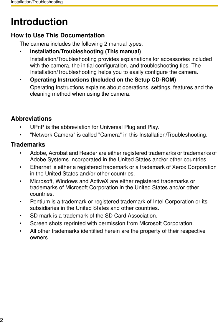
Panasonic of North America 96NBB-HCM371A 802.11b/g Wireless Camera Transmitter User Manual BBHCM371A IT
Panasonic Corporation of North America 802.11b/g Wireless Camera Transmitter BBHCM371A IT
UserManual.wiki
>
Panasonic of North America
>
96NBB HCM371A User Manual
User Manual
Navigation menu
Upload a User Manual
Namespaces
Wiki Guide
HTML
PDF
Info
Views
User Manual
Discussion / Help
Navigation
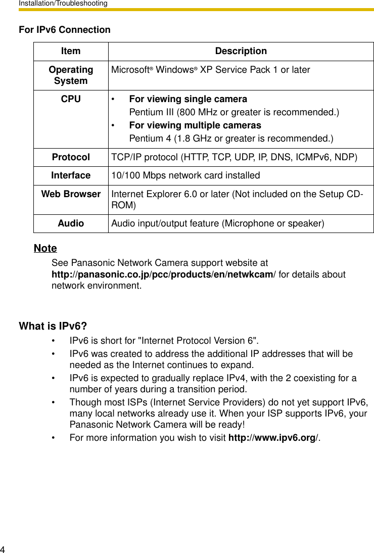
![Installation/Troubleshooting[For assistance, please call: 1-800-272-7033] 3System Requirements for your PCYour PC (Personal Computer) and network must meet the following technical specifications for the camera to work properly.For IPv4 ConnectionItem DescriptionOperating System Microsoft® Windows® XP, Microsoft® Windows® 2000Microsoft® Windows® Me, Microsoft® Windows® 98SECPU •For viewing single cameraPentium® III (800 MHz or greater is recommended.)•For viewing multiple camerasPentium 4 (1.8 GHz or greater is recommended.)Protocol TCP/IP protocol (HTTP, TCP, UDP, IP, DNS, ARP, ICMP)Interface 10/100 Mbps network card installedWeb Browser Internet Explorer 6.0 or later (Not included on the Setup CD-ROM)Audio Audio input/output feature (Microphone or speaker)](https://usermanual.wiki/Panasonic-of-North-America/96NBB-HCM371A/User-Guide-488147-Page-3.png)
![Installation/Troubleshooting[For assistance, please call: 1-800-272-7033] 5Table of Contents1 Before Using..................................................................71.1 IMPORTANT SAFETY INSTRUCTIONS........................................ 71.1.1 FCC and Other Information ....................................................................... 81.1.2 Security Cautions .................................................................................... 101.1.3 User Name and Password Protection...................................................... 101.2 Included Accessories................................................................... 111.3 Camera Feature Locations........................................................... 121.3.1 Front View................................................................................................ 121.3.2 Side View................................................................................................. 131.3.3 Bottom View ............................................................................................ 131.3.4 Rear View................................................................................................ 141.4 Connecting the Camera to Your Router ....................................... 151.5 Setting up the Camera to View on the LAN ................................. 171.6 Setting up Internet Access to the Camera ................................... 231.7 Confirming the Wireless LAN Setup ............................................ 271.8 Viewnetcam.com Service (IPv4/IPv6)..........................................281.9Connecting the Camera to a Router Supporting UPnP™ (IPv4 Only).301.10 Connecting the Camera to a Router Not Supporting UPnP™ (IPv4 Only) ............................................................................................ 311.11 Setting up the Camera Using the MAC Address on the Setup Program ....................................................................................... 321.12 Confirming the Camera Image..................................................... 351.13 Using the SD Memory Card......................................................... 381.14 Installing the Camera ................................................................... 391.14.1 Wiring the Camera................................................................................... 401.14.2 Mounting the Camera.............................................................................. 432 Troubleshooting ..........................................................472.1 Indicator Error Codes................................................................... 472.2 Camera Setup Difficulties............................................................. 492.3 About Wireless Communication................................................... 512.4 Camera Image/Page Display .......................................................522.5 Operation Bar............................................................................... 56](https://usermanual.wiki/Panasonic-of-North-America/96NBB-HCM371A/User-Guide-488147-Page-5.png)
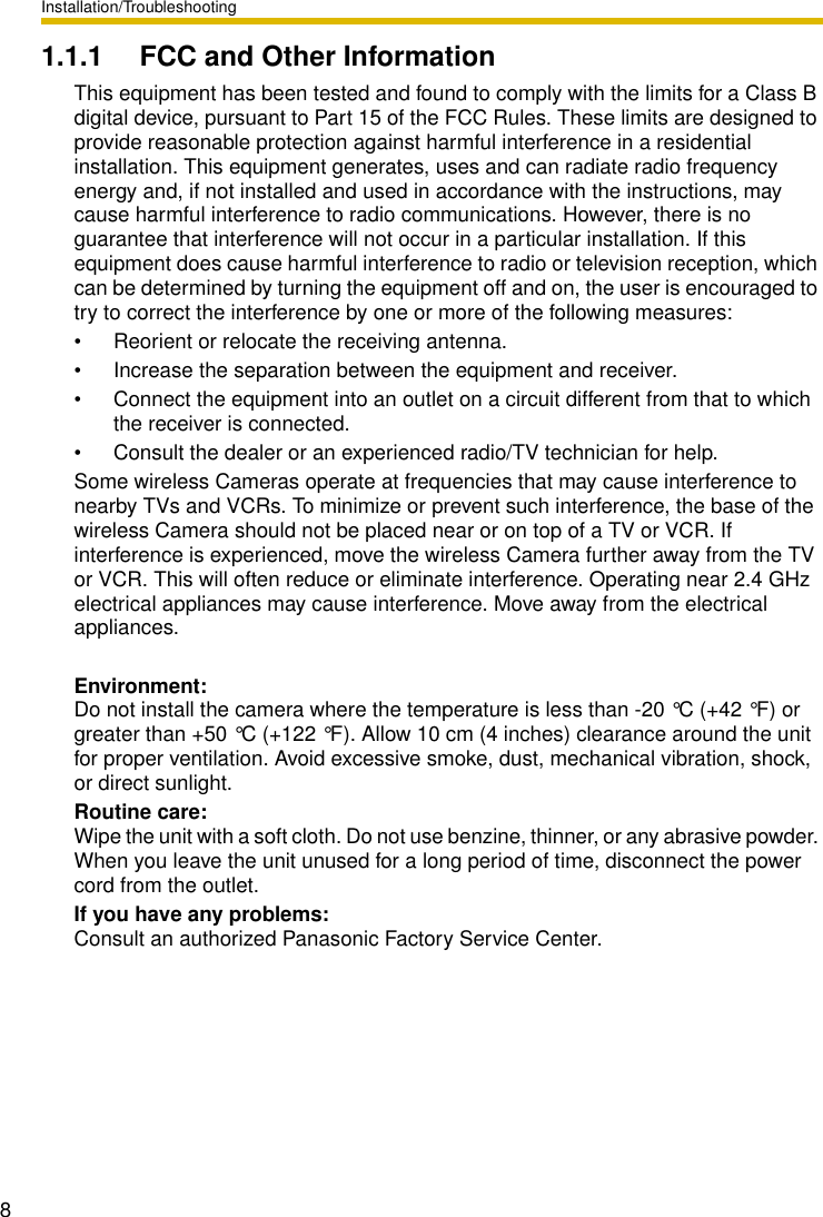
![Installation/Troubleshooting[For assistance, please call: 1-800-272-7033] 71 Before Using1.1 IMPORTANT SAFETY INSTRUCTIONSWhen using this unit, basic safety precautions should always be followed to reduce the risk of fire, electric shock, or personal injury.1. Read and understand all instructions.2. Keep these instructions.3. Heed all warnings.4. Follow all instructions.5. After taking away the sand or the dust on the lens cover, wipe the lens cover with a dry cloth.6. Do not block any ventilation openings. Install in accordance with the manufacturer's instructions.7. Do not install near any heat sources such as radiators, heat registers, stoves, or other devices (including amplifiers) that produce heat.8. Protect the AC adaptor cord and AC cord from being walked on or pinched particularly at plugs, convenience receptacles, and the point where they exit from the unit.9. The AC cord is used as the main disconnect device, ensure that the socket-outlet is located/installed near the equipment and is easily accessible.10.Only use attachments/accessories such as stand specified by the manufacturer.11.Do not touch the unit or the AC adaptor cord and AC cord during lightning storms.12.Unplug the unit when unused for long periods of time.13.Refer all servicing to qualified service personnel. Servicing is required when the unit has been damaged in any way, such as the AC adaptor, AC cord or plug is damaged, the unit does not operate normally, or has been dropped.14.The attached AC adaptor and AC cord is intended for indoor use only. Both AC adaptor and AC cord must be waterproofed for outside use.15.Keep the SD memory card (customer-provided) out of reach of children to prevent swallowing.SAVE THESE INSTRUCTIONS](https://usermanual.wiki/Panasonic-of-North-America/96NBB-HCM371A/User-Guide-488147-Page-7.png)
![Installation/Troubleshooting[For assistance, please call: 1-800-272-7033] 9FCC RF Exposure Warning• To comply with FCC RF exposure requirements in uncontrolled environment:• This equipment must be installed and operated in accordance with provided instructions and a minimum 20 cm (8 inches) spacing must be provided between antenna and all person's body (excluding extremities of hands, wrist and feet) during wireless modes of operation.• This transmitter must not be co-located or operated in conjunction with any other antenna or transmitter.•MedicalConsult the manufacturer of any personal medical devices, such as pacemakers, to determine if they are adequately shielded from external RF (radio frequency) energy. (The unit operates in the frequency range of 2.412 GHz to 2.462 GHz, and the power output level is 0.14 watts.) Do not use the unit in health care facilities if any regulations posted in the area instruct you not to do so. Hospitals or health care facilities may be using equipment that could be sensitive to external RF (radio frequency) energy.• Any changes or modifications not expressly approved by the party responsible for compliance could void the user's authority to operate this device.Audio and Video Recording NoticePLEASE NOTE that under certain circumstances, audio/video recording may be PROHIBITED by law. This device should be used only in compliance with all applicable federal, state and local statutes.No responsibility will be taken by our company with respect to consequences resulting from the use, damage or both of the camera.](https://usermanual.wiki/Panasonic-of-North-America/96NBB-HCM371A/User-Guide-488147-Page-9.png)
![Installation/Troubleshooting[For assistance, please call: 1-800-272-7033] 111.2 Included AccessoriesThe following items are provided with the camera. Additional pieces can be ordered by calling 1-800-332-5368.Main Unit—1 pc. AC Cord—1 pc.Order No.: PSJA1069Z Setup CD-ROM—1 pc.Order No.: PSQX3242ZCDStand A (Left)—1 pc.Stand B (Right)—1 pc.Installation/Troubleshooting(This manual)—1 pc.Screws for Flexible Stand—3 pcs.Order No.: PQHE5004ZAC Adaptor—1 pc.Order No.: PQLV202WSunshade—1 pc.Order No.: PSKV1051Z1Putties—1 set (4 pcs.) Order No.: PSHG1259ZSelf Bonding tape—1 pc.Order No.: PSHG1235ZConnector Cover—1 pc.Order No.: PSKV1052Z1Screws—4 pcs.Order No.: XTN26+10GVW](https://usermanual.wiki/Panasonic-of-North-America/96NBB-HCM371A/User-Guide-488147-Page-11.png)
![Installation/Troubleshooting121.3 Camera Feature Locations1.3.1 Front ViewIndicator Display*1 The indicator turns orange if the camera is not connected to the LAN.*2 The indicator blinks orange if the camera is not connected to the LAN.*3 See page 48.Lens CoverLens (0.5 m [about 20 inches]—Unlimited )IndicatorThe indicator color shows camera status.MicrophoneThe microphone picks up audio around the camera.(See page 29 of the Operating Instructions on the Setup CD-ROM)PoweronNormal Operation*1Updating FirmwareGetting IP address*2 Got IP addressSettingFinished settingNot on the LAN Orange blinkingOrange blinking(The camera restarts after that.)Pressing FACTORY DEFAULT RESET buttonOrange blinking Turning offUPnPTM Failure Orange blinking (About a 2-second interval)On the LANUsing DHCPAutomaticSetupInternal Failure Red blinking*3Orange blinking GreenGreenGreenGreenGreen blinkingGreen blinkingGreen blinkingGreen blinking](https://usermanual.wiki/Panasonic-of-North-America/96NBB-HCM371A/User-Guide-488147-Page-12.png)
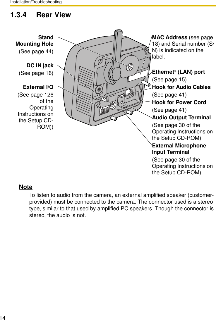
![Installation/Troubleshooting[For assistance, please call: 1-800-272-7033] 131.3.2 Side View1.3.3 Bottom ViewRESTART ButtonRestarts the camera.(see page 129 of the Operating Instructions on the Setup CD-ROM).SD Memory Card Slot(See page 38)FACTORY DEFAULT RESET ButtonResets settings to default (see page 128 of the Operating Instructions on the Setup CD-ROM).Stand/Tripod Mounting Hole (See page 43 and page 45)](https://usermanual.wiki/Panasonic-of-North-America/96NBB-HCM371A/User-Guide-488147-Page-13.png)
![Installation/Troubleshooting[For assistance, please call: 1-800-272-7033] 151.4 Connecting the Camera to Your RouterConnect the camera to your router with an Ethernet cable to set up the camera.1. Connect the Ethernet cable (customer-provided) to the camera.NoteThese instructions assume your PC is already connected to the Internet and your network includes a router.2. Connect the Ethernet cable to your router.Ethernet portEthernet cableTo your routerTo a LAN port of your routerEthernet cable (Straight Cat5 cable)(Customer-provided)To the outletTo your PCTo your modem](https://usermanual.wiki/Panasonic-of-North-America/96NBB-HCM371A/User-Guide-488147-Page-15.png)
![Installation/Troubleshooting[For assistance, please call: 1-800-272-7033] 171.5 Setting up the Camera to View on the LANSetup CD-ROM allows you to easily set up the camera.Notes• To avoid any possible problems, temporarily disable any firewall or antivirus software.• This procedure explains installation of the camera on the same network that your PC is part of.• Before proceeding, close your web browser.• See page 140 of the Operating Instructions on the Setup CD-ROM for details.• To set the Wireless Configuration, the wireless LAN settings of your router—SSID, communication mode and encryption etc.—are required. (See your wireless router's manual for your reference to the wireless LAN settings.)• When there are some cameras or PCs that are communicating wirelessly, the IP addresses may overlaps and the camera may not be able to communicate. See page "" of the Operating Instructions on the Setup CD-ROM.1. Insert the Setup CD-ROM into the CD-ROM drive of the PC.• The window is automatically displayed. (If the Network Camera Setup window is not displayed automatically, double-click "Setup.exe" file on the Setup CD-ROM.)2. Click [Camera Setup].Displays version information about this program.Sets up the camera.Displays the camera manuals. If your PC does not have Adobe® Acrobat® Reader®, install it from the Adobe Reader website.Installs Network Camera Recorder trial version.Closes the Setup Program.](https://usermanual.wiki/Panasonic-of-North-America/96NBB-HCM371A/User-Guide-488147-Page-17.png)
![Installation/Troubleshooting183. Select the camera to set up and click [Execute].• This program searches for the cameras that are connected to the router and displays the MAC Addresses, IP addresses and Port Numbers.• The MAC Address on the rear side (see page 14) of the camera shows which camera you select on the Camera List window.Notes• If more than 20 minutes have passed since the camera was turned on, the camera cannot be set up from the Setup Program. In this situation, disconnect the AC cord from the outlet, and reconnect it again.• The Setup Program may not list any cameras due to your firewall or antivirus software settings on your PC. If you cannot disable your firewall or antivirus software, you can set up the camera entering the camera MAC address on the following window. The camera's MAC address can be found on the label affixed to the back of each camera. See page 32 for details.Camera Status Camera List windowDisplays IPv4 or IPv6 information.Port No.MAC AddressIP Address](https://usermanual.wiki/Panasonic-of-North-America/96NBB-HCM371A/User-Guide-488147-Page-18.png)
![Installation/Troubleshooting[For assistance, please call: 1-800-272-7033] 194. Click [Automatic Setup (Local Access Only)].• For the first time installation or after pressing the FACTORY DEFAULT RESET button, only [Automatic Setup (Local Access Only)] can be selected. To set up the camera with Static or DHCP settings, after performing the [Automatic Setup (Local Access Only)], run the Setup Program again and select [Manual Setup].5. Enter the user name and password you wish to use, and click [Save].6. Enter the name and password that were entered above, and click [OK].](https://usermanual.wiki/Panasonic-of-North-America/96NBB-HCM371A/User-Guide-488147-Page-19.png)
![Installation/Troubleshooting207. To set the Wireless Configuration, check [Enable] and click [Next>].• When [Disable] was selected, skip to step 9.• The Wireless Configuration can also be set at in the Setup Page. (See page "" of the Operating Instructions in the Setup CD-ROM.)8. Set the Wireless Configuration according to the wireless settings of the router and click [Next>].• For more information about wireless setting, see http://panasonic.co.jp/pcc/products/en/netwkcam/technic/wireless/cam_set.html1. Set the SSID.Set the name of the wireless network.2. Select the Communication mode.They are IEEE Communication modes. Select the same Communication mode as that of the router to which the camera is connected.802.11b (IEEE802.11b) : Only 802.11b wireless router can be connected.802.11b/g (IEEE802.11g) : Either 802.11b or 802.11g router can be connected.802.11g exclusive (IEEE802.11g) : Only 802.11g router can be connected.1234](https://usermanual.wiki/Panasonic-of-North-America/96NBB-HCM371A/User-Guide-488147-Page-20.png)
![Installation/Troubleshooting[For assistance, please call: 1-800-272-7033] 213. Select encrypting or not encrypting.Selecting WEP can encrypt data within the wireless LAN.4. Set the WEPKey1–4.Selecting [WEP] at Cipher enables you to set WEPKey1–4. One or all of the four keys can be set. Check the same key number as set to the router, and set the same key as at the router.<Example>9. When the Single Camera page is displayed, the setup is completed.• When Security Warning window is displayed, click [Yes]. (See page 37)WEP : Encrypting (setting WEP) makes it difficult for unauthorized users to read data within the wireless LAN, even if they can receive it. To encrypt data, set the same encryption key to every terminal within the wireless LAN. There are 3 kinds of encryption key: 64 bit, 128 bit and 152 bit. Security level of encryption increases in order of length as follows: 64 bit, 128 bit and 152 bit.No encryption : select when not using encryption.:The entered WEPKey will be displayed as " "s regardless of the key type selected.HEX, 10 characters 64 bit : 012345abcdHEX, 26 characters 128 bit : 0123456789abcdef012345abcdHEX, 32 characters 152 bit : 0123456789abcdef0123456789abcdefASCII 5 characters 64 bit : 012yzASCII 13 characters 128 bit : 0123456uvwxyzASCII 16 characters 152 bit : 0123456789uvwxyz](https://usermanual.wiki/Panasonic-of-North-America/96NBB-HCM371A/User-Guide-488147-Page-21.png)
![Installation/Troubleshooting22• When having set the wireless configuration, follow "1.7 Confirming the Wireless LAN Setup" on page 27.NoteTo insure that the most current image is displayed, Internet Explorer should be configured as follows. This will not have any negative result on normal use.To enable Internet access to the cameraClick [Next] to set up the Internet access to the camera and go to step 3 on the page 24.• If you do not allow the Internet access, click [Cancel], and go to page 35 to confirm the camera image.1. While viewing any website, Click [Tools] [Internet Options].2. In the section "Temporary Internet Files", click [Settings] and check [Every visit to the page].](https://usermanual.wiki/Panasonic-of-North-America/96NBB-HCM371A/User-Guide-488147-Page-22.png)
![Installation/Troubleshooting[For assistance, please call: 1-800-272-7033] 231.6 Setting up Internet Access to the Camera1. Display the Camera List window (see page 17—page 18).2. Select the camera to set up and click [Execute].• This program searches for the cameras that are connected to the router and displays the MAC Addresses, IP addresses and Port Numbers.• The MAC Address on the rear side (see page 14) of the camera shows which camera you select on the Camera List window.NoteIf more than 20 minutes have passed since the camera was turned on, the camera cannot be set up from the Setup Program. In this situation, restart the camera.Camera Status Camera List windowDisplays IPv4 or IPv6 information.Port No.MAC AddressIP Address](https://usermanual.wiki/Panasonic-of-North-America/96NBB-HCM371A/User-Guide-488147-Page-23.png)
![Installation/Troubleshooting243. Click [Automatic Setup (Internet Access)].NoteIn order for Internet access to be properly enabled, your routers UPnPTM feature should be enabled. Most router manufacturers disable this feature. See http://panasonic.co.jp/pcc/products/en/netwkcam/technic/rtr_setup for more information. 4. Enter the user name and password that were set, and click [OK].5. To enable Internet access, select [Enable]. Choose [Disable] if you wish to restrict access to your local network.• If you use a router not supporting UPnPTM, click [Disable]. If you select [Disable], skip to step 9.Sets up the camera to view on the LAN.Sets up the Internet access to the camera.Manually sets up the camera.Disables IPsec. If disabled, the button is displayed gray.Displays the Setup page (see page 39 of the Operating Instructions on the Setup CD-ROM).](https://usermanual.wiki/Panasonic-of-North-America/96NBB-HCM371A/User-Guide-488147-Page-24.png)
![Installation/Troubleshooting[For assistance, please call: 1-800-272-7033] 256. To register with the "Viewnetcam.com FREE DDNS service", check [Register with Viewnetcam.com] and click [Next].Viewnetcam.com FREE DDNS serviceSee page 28 for Viewnetcam.com information. For detailed information, access at http://www.viewnetcam.com.• If you have multiple cameras, you can use Viewnetcam.com service registering it only for a camera.• If you select [Disable], skip to step 9.7. The Enter Network Password window is displayed, and enter the user name and password that were set, and click [OK].8. After a while, the "Viewnetcam.com FREE DDNS service" website is displayed. Follow the displayed instructions for registration.• If the message "Failed to configure the router's Port Forwarding by UPnP" is displayed, your router may not support UPnPTM or UPnPTM is not enabled. Enable your router's UPnPTM or set Port Forwarding manually following the router's manual and try Automatic Setup again. For more information about setting up a router, refer to the Panasonic Network Camera support website at http://panasonic.co.jp/pcc/products/en/netwkcam/technic/rtr_setup.• If the message "Failed to register with Viewnetcam.com." is displayed, confirm that the router is connected to the Internet.](https://usermanual.wiki/Panasonic-of-North-America/96NBB-HCM371A/User-Guide-488147-Page-25.png)
![Installation/Troubleshooting269. When "Setup complete" is displayed, and click [To Single Camera page].• The port number must be specified at the end of camera URL.Using port 80:http://(Cameraname).viewnetcam.comor http://IP AddressUsing any other port:http://(Cameraname).viewnetcam.com:Port Numberor http://IP Address:Port Number10.When the Single Camera page is displayed, the setup is completed.Notes• The banner is displayed only when Internet access is allowed on the camera.• To insure that the most current image is displayed, Internet Explorer should be configured as follows. This will not have any negative result on normal use.•When [Enable] was selected at step 5 •When [Disable] was selected at step 51. While viewing any website, Click [Tools] [Internet Options].2. In the section "Temporary Internet Files", click [Settings] and check [Every visit to the page].](https://usermanual.wiki/Panasonic-of-North-America/96NBB-HCM371A/User-Guide-488147-Page-26.png)
![Installation/Troubleshooting[For assistance, please call: 1-800-272-7033] 271.7 Confirming the Wireless LAN SetupAfter setting each item for the wireless LAN, confirm that the camera works correctly.1. Start up the web browser on the PC.2. Enter "http://IP address (or URL):Port No." in the address field and press [Enter].(When port number is 80 (default), you do not need to enter port number.)3. When the following Top Page is displayed, the wireless LAN setup is successful.• If the Top Page was not displayed, the settings for the camera are not identical with those for the router. Check the settings by using wired connection.If the settings are correct and you use a proxy server, set the web browser not to access the proxy server.If the Top Page is not displayed even after trying these methods, contact the retailer.• It takes about 1 minute for the new settings to be effective.• It is not possible to access the camera simultaneously by both wired and wireless connection.](https://usermanual.wiki/Panasonic-of-North-America/96NBB-HCM371A/User-Guide-488147-Page-27.png)
![Installation/Troubleshooting[For assistance, please call: 1-800-272-7033] 29Notes• Ask your ISP about what type of IP address you are using.• Some ISPs assign you a local IP address. In this case, you cannot use the Viewnetcam.com service. Ask you ISP about what type of IP address you are using.• If the camera is using a port number other than 80, the port number must be specified at the end of the Viewnetcam URL. For example:Using port 80: http://(Cameraname).viewnetcam.comUsing any other port: http://(Cameraname).viewnetcam.com:Port Number](https://usermanual.wiki/Panasonic-of-North-America/96NBB-HCM371A/User-Guide-488147-Page-29.png)
![Installation/Troubleshooting[For assistance, please call: 1-800-272-7033] 311.10 Connecting the Camera to a Router Not Supporting UPnP™ (IPv4 Only)To allow access from the Internet with a router not supporting UPnPTM, follow the procedures below.1. Select [Static] on the Network (IPv4) page.2. Enable port forwarding on the router.Using the IP address and port number note written on step 1-(3), enable port forwarding on the router. See the router manual for how to enable port forwarding.3. Register with the Viewnetcam.com service.Port Forwarding feature*1 (IPv4 Only)The port forwarding feature is required to allow access from the Internet with a router not supporting UPnPTM. It exchanges a local IP address to a global one. Each camera must be assigned a unique port number.(1) Access the camera (see page 13 of the Operating Instructions on the Setup CD-ROM).(2) Click [Setup] tab at the top of the page.(3) Select [Static] on the Network page.• The Static IP Address Configuration page is displayed. Make a note of the IP address and port number, since they are required to enable port forwarding on the router.(4) Click [Save] without changing the settings.(5) Click [Restart].*1 "Port forwarding" may be called "Address translation", "Static IP Masquerade", "Virtual server" or "Port mapping" in other products.Global IP address of the routervvv.xxx.yyy.zzz:80vvv.xxx.yyy.zzz:81vvv.xxx.yyy.zzz:80 192.168.0.253:80vvv.xxx.yyy.zzz:81 192.168.0.252:81Port No.Port Forwarding featureLocal IP addressThe IP addresses shown above may differ from those offered on your home network.Note192.168.0.1192.168.0.252Port No. 81 192.168.0.253Port No. 80RouterModemCATVxDSLOptical cableInternet](https://usermanual.wiki/Panasonic-of-North-America/96NBB-HCM371A/User-Guide-488147-Page-31.png)
![Installation/Troubleshooting321.11 Setting up the Camera Using the MAC Address on the Setup ProgramThe Setup Program may not list any cameras due to your firewall or antivirus software settings on your PC. If you cannot disable your firewall or antivirus software, you can set up the camera using the camera MAC address as shown below.1. Enter the camera MAC address in the data field, and click [Set up camera].NoteThe cameras MAC address can be found on the sticker affixed to the back of the camera (see page 14).2. After confirming the network settings, click [OK].• After about a minute, the Security: Administrator page is displayed.](https://usermanual.wiki/Panasonic-of-North-America/96NBB-HCM371A/User-Guide-488147-Page-32.png)
![Installation/Troubleshooting[For assistance, please call: 1-800-272-7033] 333. Enter the user name and password, and click [Save].4. The Enter Network Password window is displayed. Enter the user name and password that were set, and click [OK].](https://usermanual.wiki/Panasonic-of-North-America/96NBB-HCM371A/User-Guide-488147-Page-33.png)
![Installation/Troubleshooting345. When the Single Camera page is displayed, the setup is completed.• If Security Warning window is displayed, click [Yes] (see page 37).Notes• See page 17 of the Operating Instructions on the Setup CD-ROM for the Single Camera page.• If you enable the Internet access to the camera, follow the procedures below.•When you are using a router supporting UPnPTM•When you are using a router not supporting UPnPTMFollow the procedures shown on page 31.1. Enable the Auto Port Forwarding feature on the UPnP page (see page 63 of the Operating Instructions on the Setup CD-ROM).2. Register with the Viewnetcam.com service on the Viewnetcam.com page (see page 65 of the Operating Instructions on the Setup CD-ROM).3. Confirm the Internet access to the camera (see page 35).](https://usermanual.wiki/Panasonic-of-North-America/96NBB-HCM371A/User-Guide-488147-Page-34.png)
![Installation/Troubleshooting[For assistance, please call: 1-800-272-7033] 351.12 Confirming the Camera Image1. Start up the web browser on your PC.2. Enter "http://IPv4 Address (or URL):Port Number" on the address bar, and press [Enter] on the keyboard.• When port number is 80 (default), you do not need to enter port number. See page 44 of the Operating Instructions on the Setup CD-ROM for details about port number.• For IPv6 connection, see page 15 and page 16 of the Operating Instructions on the Setup CD-ROM and prepare the requirements. Enter the "http://(IPv6-registered URL):Port Number" on the address bar.• If the camera image is not displayed, see page 52.3. The Enter Network Password window is displayed, and enter the user name and password that were set, and click [OK].NoteWhen [Permit access from guest users] is set on the Security: Administrator page, authentication window will not be displayed.4. Click the following tabs to display each page.ATo Single Camera page (page 17 of Operating Instructions) BTo Multi-Camera page (page 32 of Operating Instructions)CTo Buffered Image page (page 34 of Operating Instructions) DTo Setup page (page 39 of Operating Instructions)ETo Maintenance page (page 114 of Operating Instructions) FTo Support page (page 123 of Operating Instructions)GTo log in to the camera (page 78 of Operating Instructions)A B C D E F GSelect a language to display.Displays IPv4, IPv6 or IPsec connection.Version Number](https://usermanual.wiki/Panasonic-of-North-America/96NBB-HCM371A/User-Guide-488147-Page-35.png)
![Installation/Troubleshooting36Notes• When users other than an administrator are accessing the camera, [Setup] and [Maintenance] tab will not be displayed. Additionally, When [Do not permit access from guest users] is set on the Security: Administrator page, [Login] tab will not be displayed.• If [View Multi-Camera page] or [View Buffered Image page] is not permitted on the General User page, [Multi-Camera] or [Buffered Image] tab will not be displayed.5. Click [Single] tab on the above.• When Security Warning window is displayed, click [Yes]. (See page 37)NoteFor IPv6 connection, see page 15 and page 16 of the Operating Instructions on the Setup CD-ROM.6. Close the web browser.Talk Button(see page 29 ofthe OperatingInstructions)Capture ImageButton(see page 22 ofthe OperatingInstructions)Operation Bar(see page 23 ofthe OperatingInstructions)Refresh Interval(see page 23 ofthe OperatingInstructions)Listen Button and Adjustment Bar(see page 29 of the Operating Instructions)Click to Center(see page 21 of the Operating Instructions)Camera ImageThe banner is displayed.(see page 20 of the Operating Instructions)](https://usermanual.wiki/Panasonic-of-North-America/96NBB-HCM371A/User-Guide-488147-Page-36.png)
![Installation/Troubleshooting[For assistance, please call: 1-800-272-7033] 37Security Warning windowTo view a video (Motion JPEG) or to use audio feature, ActiveX® Controls must be installed. When trying to display a video for the first time, Security Warning window will be displayed. When using Windows 2000 or Windows XP, log in as an administrator to install it.If you cannot install ActiveX Controls or you cannot see the video in the Internet Explorer• Click [Tools] [Internet Options] [Security] tab and click [Custom level] on the web browser. (1) Check "Prompt" in "Download signed ActiveX Controls".(2) Check "Enable" in "Run ActiveX Controls and plug-ins".• ActiveX Controls can be installed from the file on the Setup CD-ROM.(1) Restart the PC. (2) Confirm that Internet Explorer is closed. (3) Double-click"ocx\ActiveXInst.exe" on the Setup CD-ROM.Notes• Video may not be displayed quickly or audio may not be listened immediately. Wait for a while.• If you use a proxy server, set the web browser not to access the proxy server (see page 143 of the Operating Instructions on the Setup CD-ROM).• In some corporate network environments a firewall may be used for security purposes. It is possible that this may prevent motion video from being displayed. In this situation we suggest:• Contact your network administrator.• Try using regularly refreshed images.](https://usermanual.wiki/Panasonic-of-North-America/96NBB-HCM371A/User-Guide-488147-Page-37.png)
![Installation/Troubleshooting[For assistance, please call: 1-800-272-7033] 391.14 Installing the CameraThe camera has a splash resistant body. The splash resistant body allows the camera to be used indoors and outdoors. Waterproof cabling is necessary for outdoor mounting. Check the camera operation before installing (cabling and mounting) the camera.Notes• Install the camera under eaves to protect it from direct sunlight. Prolonged exposure to direct sunlight or halogen light may damage the CCD sensor.• Use the sunshade in any conditions.• Do not install the camera in the location where sea breezes may hit the unit directly.• Avoid laying Ethernet cable underground or stringing it in the air. Lightning may cause serious damage to the camera or the connected devices.• AC adaptor and AC cord are not waterproofed. Put them inside the outdoor power equipment near the camera and protect them from the rain. Ask the authorized electric wiring dealer.• AC adaptor, AC cord and Ethernet cable should be waterproofed. Do the waterproof electric wiring work.• Do not expose the AC adaptor to the temperatures below -20 °C (-4 °F) or above +50 °C (122 °F). AC adaptor cannot be operated under these circumstances.](https://usermanual.wiki/Panasonic-of-North-America/96NBB-HCM371A/User-Guide-488147-Page-39.png)
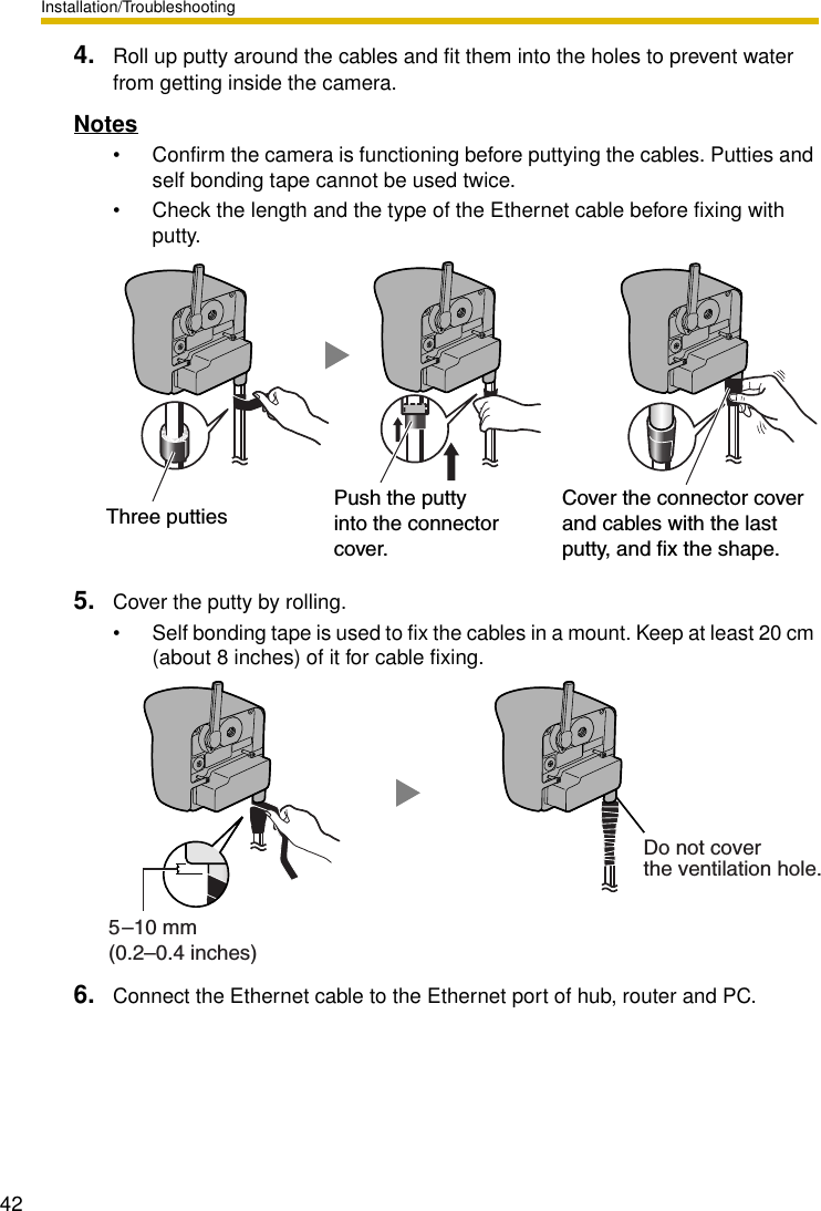
![Installation/Troubleshooting401.14.1 Wiring the CameraCheck the location where the camera should be installed. Select the proper cable suited to the camera location. Consult an authorized wiring electrician for cabling.The camera can be mounted in the following ways.1. Put the cables through the connector cover (1.). Connect the DC plug of the AC adaptor to the DC IN jack (2.) and Ethernet cable to the Ethernet port (3.). Connect the AC plug of the AC cord to the outlet (4.).• If you use External I/O, external speaker or external microphone, put the cables through the connector cover.Notes• Confirm that the indicator lights green.• Check the location of the camera, the type and the length of the Ethernet cable (Max. 100 m [330 feet]). Use an Ethernet cable as short as possible for outdoor use. Lightning may cause serious damage to the camera or the connected devices.Ethernet portDC IN jackExternal I/O(1.)ConnectorCoverAC adaptor(4.)OutletTo Network(2.) DC PlugEthernet cable(3.)](https://usermanual.wiki/Panasonic-of-North-America/96NBB-HCM371A/User-Guide-488147-Page-40.png)
![Installation/Troubleshooting[For assistance, please call: 1-800-272-7033] 412. Thread the AC adaptor cord through the hook. Put the connector cover by fastening the two screws in numerical order. The remaining screw hole on the connector cover is used for attaching sunshade.NoteWhen you mount the camera, always hook the AC adaptor cord and audio cables to the hooks.3. Attach the sunshade by fastening the two screws.Hook for Power Cord Hook for Audio CablesConnector coverScrew(accesories)Screw holeAC adaptor cordHook3Sunshade(accessories)Screw(accessories)4](https://usermanual.wiki/Panasonic-of-North-America/96NBB-HCM371A/User-Guide-488147-Page-41.png)
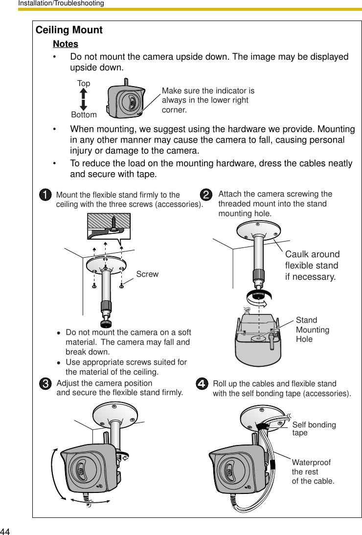
![Installation/Troubleshooting[For assistance, please call: 1-800-272-7033] 431.14.2 Mounting the CameraFour mounting methods are shown in the following figures. Confirm the top and bottom of the camera when mounting. Ask the authorized dealer for mounting.NoteMounting and cabling instructions described in this Installation/Troubleshooting follow generally accepted guidelines suitable for residential installations. In some areas, commercial and industrial installations are regulated by local or state ordinances. For such installations, contact your local building department or building inspector for more details.Flexible Stand MountTripod MountStand/Tripod Mounting HoleFlexible StandScrew the threaded mount into the stand/tripodmounting hole.Fit Stand A with Stand B.Turn the grip firmly.Stand/Tripod Mounting HoleTripod](https://usermanual.wiki/Panasonic-of-North-America/96NBB-HCM371A/User-Guide-488147-Page-43.png)
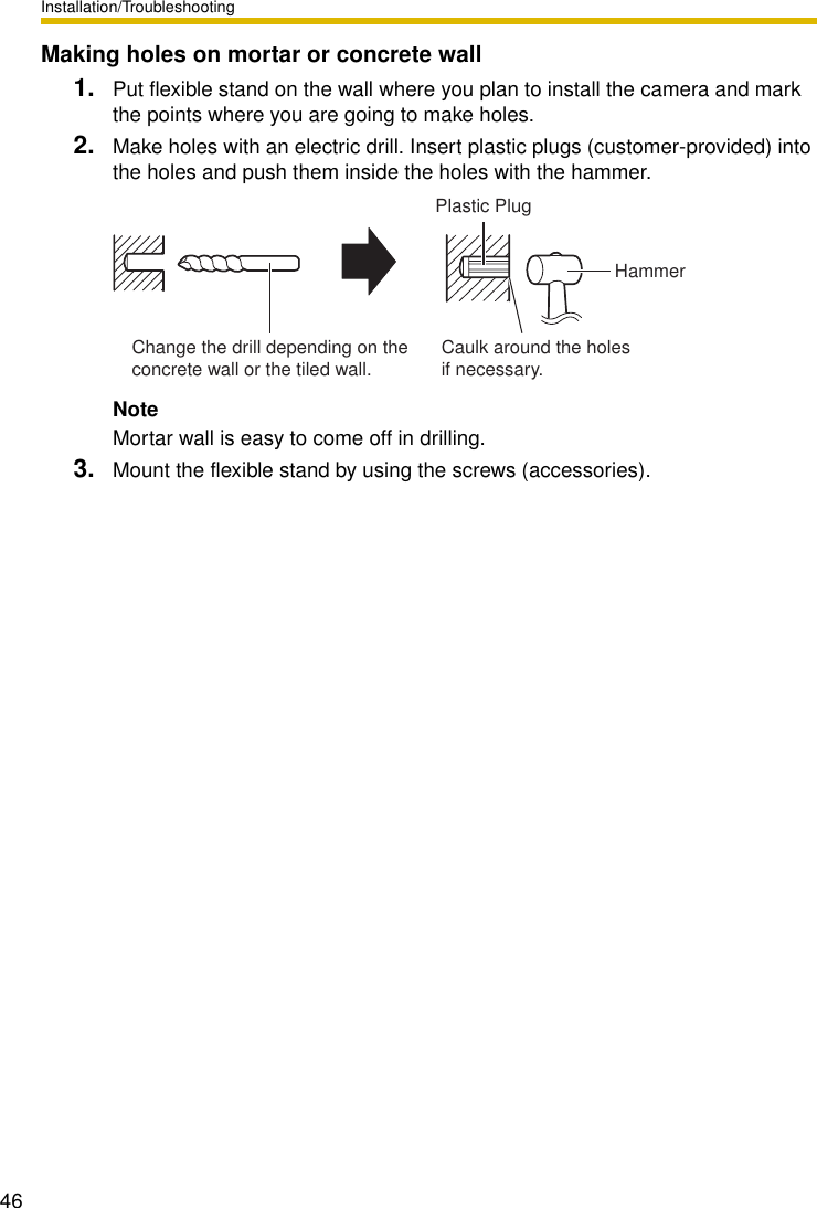
![Installation/Troubleshooting[For assistance, please call: 1-800-272-7033] 45Wall MountNotes• Drive mounting screws into the wall. Be careful to avoid touching any metalwork (metal/wire laths etc.), conduits or electrical cables buried in the wall.• Do not mount the camera upside down. The image may be displayed upside down.• When mounting, we suggest using the hardware we provide. Mounting in any other manner may cause the camera to fall, causing personal injury or damage to the camera.• To reduce the load on the mounting hardware, dress the cables neatly and secure with tape.165 mm(6.5 inches)Self bonding tapeWaterproof the rest of the cable.ScrewMount the flexible stand firmly to the wall with the three screws (accessories).Attach the camera screwing the threaded mount into the stand/tripod mounting hole.Adjust the camera position and secure the flexible stand firmly.Roll up the cables and flexible stand with the self bonding tape (accessories).Do not mount the camera on a soft material. The camera may fall and break down.Use appropriate screws suited for the material of the ceiling.Caulk aroundflexible standif necessary.Stand/Tripod Mounting HoleIndicator](https://usermanual.wiki/Panasonic-of-North-America/96NBB-HCM371A/User-Guide-488147-Page-45.png)
![Installation/Troubleshooting[For assistance, please call: 1-800-272-7033] 472 TroubleshootingThe Panasonic Network Camera support website "http://panasonic.co.jp/pcc/products/en/netwkcam/" includes various technical information other than the contents in this troubleshooting section. Access it if problems occur.2.1 Indicator Error CodesProblem Cause and RemedyIndicator lights or blinks orange. • Ethernet cable is not connected properly.Connect the Ethernet cable properly.• PC, Ethernet hub or router is not working.Confirm that PC, Ethernet hub and router is working.• The wireless settings are not identical with those of the router.Set the same SSID, Communication mode and WEP as those of the router.Indicator continues blinking orange.• Indicator blinks orange when updating firmware.If you access the camera on the web browser, Update Firmware page will be displayed. Update the firmware following the procedure (see page 117 of the Operating Instructions on the Setup CD-ROM). If you fail to update the firmware, see page 64.Indicator continues blinking orange (2-second interval).• The router on your network is turned off.Turn the router on, and wait for a while until the ADSL line is connected.• An error occurs in UPnPTM port forwarding.Set up the camera again in [Automatic Setup] by the Setup Program following the Getting Started.Indicator continues blinking green.• Automatic setup is not complete.Complete the setup following this Installation/Troubleshooting.• The camera did not get its IP address from the DHCP server.When setting [Automatic Setup] or [DHCP Setup], the camera may not get its IP address due to network failures. Ask your ISP or network administrator for more information.](https://usermanual.wiki/Panasonic-of-North-America/96NBB-HCM371A/User-Guide-488147-Page-47.png)
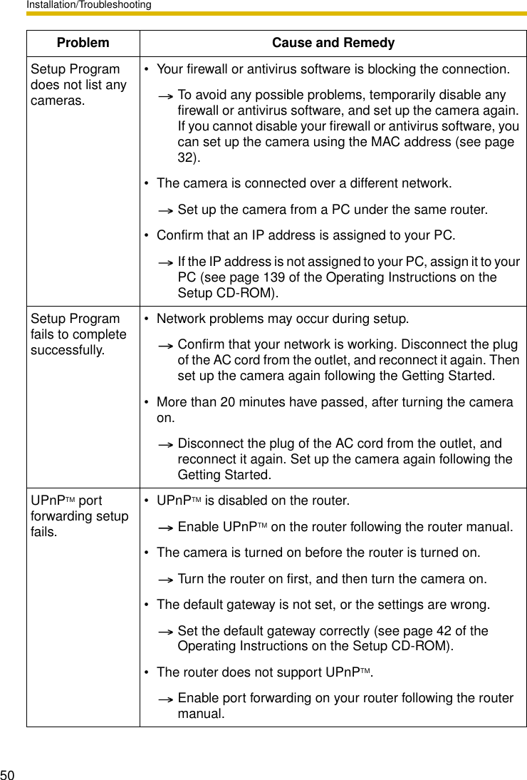
![Installation/Troubleshooting[For assistance, please call: 1-800-272-7033] 492.2 Camera Setup DifficultiesNoteIf you are experiencing any problems, it is recommended that you temporarily disable all firewall, pop-up killer, and virus detection software. Once the problem is identified and corrected, you can restart the Setup Program.Problem Cause and RemedyAutomatic Setup fails using Setup Program.• More than 20 minutes have passed, after turning the camera on.Disconnect the plug of the AC cord from the outlet, and reconnect it again. Set up the camera again following the Getting Started.• Multiple camera IP addresses are overlapping.If you install multiple cameras, turn the camera on one by one.Viewnetcam.com registration fails using Setup Program.• Your PC is not connected to the Internet through the router.Configure the router for the Internet connection from your PC following the router manual. And register with the Viewnetcam.com service.• If you do not receive an E-mail from the Viewnetcam.com service, your registered E-mail address may be incorrect. Register your correct E-mail address again at the Viewnetcam.com website at http://www.viewnetcam.com.](https://usermanual.wiki/Panasonic-of-North-America/96NBB-HCM371A/User-Guide-488147-Page-49.png)
![Installation/Troubleshooting[For assistance, please call: 1-800-272-7033] 512.3 About Wireless CommunicationThe camera IP address and port number have been forgotten.• Clicking [Camera Setup] on the Setup Program displays the camera list. The camera list shows the MAC address labeled beside the Ethernet (LAN) port. The camera IP address and port number are shown next to the MAC address.The password has been forgotten.• Press the FACTORY DEFAULT RESET button to reset the camera to default. Set up the camera again.Error is displayed on the camera status by the Setup Program.• The Setup Program causes the error message.Disconnect the plug of the AC cord from the outlet, and reconnect it again.Problem Cause and RemedyWireless communication does not work.• Signal strength is weak.Change the location of the camera or get rid of the obstacle around the camera.• SSID and Encryption setting of the camera are different from those of the wireless router or the wireless LAN card of PC.SSID and Encryption setting must be identical between the camera and wireless router.Wireless communication is unstable.• The channel for communication is identical with another wireless network.The wireless communication may be improved by changing the channel of the router.• Another nearby wireless device may be causing interference or the distance between the wireless camera and your wireless network may be too great.Temporarily disable other wireless devices to identify the source of the interference.Try repositioning the camera or moving it closer to your wireless router.Problem Cause and Remedy](https://usermanual.wiki/Panasonic-of-North-America/96NBB-HCM371A/User-Guide-488147-Page-51.png)
![Installation/Troubleshooting522.4 Camera Image/Page DisplayProblem Cause and RemedyThe Top page is not displayed. • The camera IP address has changed.Enter the new IP address in the address bar of the web browser.• Wrong IP address class is assigned to the camera.IP addresses of the PC and the camera must be in the same local IP address class. Set the IP address correctly (see page 139 of the Operating Instructions on the Setup CD-ROM).• Router does not have a loopback feature.Access the camera with the local network IP address.• You entered IPv6 address in the Internet Explorer.Internet Explorer does not support IPv6 address access. Use DDNS services like Viewnetcam.com service.• The network is congested.Pages may not be displayed immediately. Wait for a while.• The web browser is accessing the proxy server.Set the web browser to access the Internet directly (see page 143 of the Operating Instructions on the Setup CD-ROM).• The connection type is wrong (see page 45 of the Operating Instructions on the Setup CD-ROM).If the camera is not connected to the network in the [Auto Negotiation] setting, set up the camera and the router seeing the following table.Auto NegotiationNetwork CameraRouter or hubAuto Negotiation100Base-TX 10Base-TXFull Duplex Half Duplex Full Duplex Half Duplex100Base-TX10Base-TFull DuplexHalf DuplexFull DuplexHalf Duplex——————————————— —](https://usermanual.wiki/Panasonic-of-North-America/96NBB-HCM371A/User-Guide-488147-Page-52.png)
![Installation/Troubleshooting[For assistance, please call: 1-800-272-7033] 53The Top page is not displayed. • The default gateway or DNS server addresses may be wrong. The correct IP addresses are required especially when you are using the Viewnetcam.com service.Assign the correct default gateway and DNS server addresses (see page 42 of the Operating Instructions on the Setup CD-ROM).The Top page is displayed on the LAN, but not displayed from the Internet.• The default gateway address may be wrong.Assign the correct default gateway address (see page 42 of the Operating Instructions on the Setup CD-ROM).•UPnPTM is disabled on the router.Enable UPnPTM on the router following the router manual.• Port forwarding is not enabled on the router (see page 31).Enable port forwarding seeing the router manual for details.• Firewalls such as packet filtering on the router is blocking camera access.Set the router to allow access to the camera seeing the router manual for details.• You are accessing the camera with an IP address for local camera access.Access the camera with the global IP address of the router and port number of the camera.• The router does not allow access to the camera under the router with the global IP address.If you access the camera on the LAN, access with the address for local camera access.Authentication windows are consequently displayed.• User name and password for the administrator or general users are changed.Close the web browser, and access the camera again.Only half of the image is displayed.• You are using Internet Explorer 4.xx or lower.Upgrade Internet Explorer to version 6.0 or greater. Problem Cause and Remedy](https://usermanual.wiki/Panasonic-of-North-America/96NBB-HCM371A/User-Guide-488147-Page-53.png)
![Installation/Troubleshooting54Camera image is not displayed. • ActiveX Controls are not installed in Internet Explorer.ActiveX Controls should be installed to display video (Motion JPEG) (see page 37).• The network is congested.Pages may not be displayed immediately. Wait for a while.• The web browser is accessing the proxy server.Set the web browser to access the Internet directly (see page 143 of the Operating Instructions on the Setup CD-ROM).A gray screen is displayed. • There are currently more than 30 simultaneous accesses to the video (Motion JPEG).Reduce the number of access to below 30, or change the video to still images.• Operation time has been specified.A gray screen is displayed outside the operation time. This is normal.Video suddenly changes to still images.• The video (Motion JPEG) display period is set on the General User page.When you view video continuously, set [Unlimited] for the limit continuous motion JPEG (see page 79 of the Operating Instructions on the Setup CD-ROM).Image is out of focus. • The lens cover has dust, dirt, fingerprints or droplets on it.Clean the lens cover with a dry cloth (see page 138 of the Operating Instructions on the Setup CD-ROM).• The object is too close to the camera.The camera cannot focus at short distances (less than 0.5 m [about 20 inches]). Locate the object more than 0.5 m (about 20 inches) away from the camera.Problem Cause and Remedy](https://usermanual.wiki/Panasonic-of-North-America/96NBB-HCM371A/User-Guide-488147-Page-54.png)
![Installation/Troubleshooting[For assistance, please call: 1-800-272-7033] 55The color on the image is strange.• White balance does not work well.Adjust the white balance on the Camera page (see page 69 of the Operating Instructions on the Setup CD-ROM).• The color display setting on your PC is set lower than 16 bits.Set the color display 16 bits or higher.Image flickers. • The object is dark.Make the area around the camera brighter.• A bright object may cause horizontal flickers on the image.Changing the object improves the flickers. Or adjusting brightness to the [+] side on the operation bar eases the flickers.An old image is displayed. • The old image is temporarily stored on the web browser.Set [Every visit to the page] on the web browser to check for temporary Internet files (see page 146 of the Operating Instructions on the Setup CD-ROM).The image refreshes very slowly.• Multiple users are accessing the camera.If multiple users are accessing the camera, the image refreshes slowly.• You are not using an Ethernet switching hub.If you view multiple cameras on the Multi-Camera page, the image refreshes slowly. Use an Ethernet switching hub.• The image may refresh slowly, depending on image resolution, image quality, network traffic, PC performance, enabling IPsec, SD memory recording or what object you view.• The Max. bandwidth usage is limited.Increase the max. bandwidth usage on your network (see page 42 of the Operating Instructions on the Setup CD-ROM).• The camera is in color night view mode.The image refreshes slowly in color night view mode. Make the area around the camera brighter.Problem Cause and Remedy](https://usermanual.wiki/Panasonic-of-North-America/96NBB-HCM371A/User-Guide-488147-Page-55.png)
![Installation/Troubleshooting562.5 Operation BarThe image stops refreshing during the wireless communication with the camera.• The image may stop refreshing because the wireless communication can be disconnected depending on the environment.Click [Refresh] at the tool bar on the web browser.Problem Cause and RemedyPan/tilt, click to center and preset features do not work.• Your PC is not connected to the camera.Click [Refresh] on the web browser. Confirm that the image refreshes, and operate the pan/tilt functions.• The camera is not turned on.Confirm that the camera is turned on.• Multiple users are operating the camera simultaneously.Wait for a while, and access the camera again.• The pan/tilt reaches its end.Confirm that the end display is displayed on the operation bar. • The pan/tilt range is restricted.Adjust the pan/tilt range settings (see page 72 of the Operating Instructions on the Setup CD-ROM).Part of the buttons on the operation bar are not displayed.• The feature is not permitted on the General User page.Permit the feature to be used (see page 79 of the Operating Instructions on the Setup CD-ROM). Or log in to the camera as an administrator.Problem Cause and Remedy](https://usermanual.wiki/Panasonic-of-North-America/96NBB-HCM371A/User-Guide-488147-Page-56.png)
![Installation/Troubleshooting[For assistance, please call: 1-800-272-7033] 572.6 Audio ProblemsProblem Cause and RemedyThe audio buttons are not displayed.• The [Output] or [Input] settings are set to [Disable] on the Audio page.Change them to [Enable]. (See page 73 of the Operating Instructions on the Setup CD-ROM)• In the access level settings on the General User page, [Listen] and [Talk] are not permitted.Permit [Listen] and [Talk]. (See page 79 of the Operating Instructions on the Setup CD-ROM)Neither Listen or Talk button can be used.• When accessing a camera on a LAN, the web browser settings are going through a proxy server.Change the settings so that they do not go through a proxy server. (see page 143 of Operating Instructions on the Setup CD-ROM)Audio cannot be heard on the computer.•The Listen button appears like this: Click the Listen button. (It will change to .)• The audio operation toolbar display is gray.[Listen] is not permitted on the General User page. Permit it. (see page 79 of Operating Instructions on the Setup CD-ROM)• The volume is set to minimum.Adjust the volume on the volume adjustment toolbar.• The computer volume is set to mute or minimum volume.Open the PC's Volume Control window, and clear the output master and Wave/MP3's Mute checkbox, then adjust the volume.• appears in the audio toolbar.There are too many simultaneous audio connections. Wait for a while, and try to access again.](https://usermanual.wiki/Panasonic-of-North-America/96NBB-HCM371A/User-Guide-488147-Page-57.png)
![Installation/Troubleshooting58Audio is not produced from an external speaker connected to the camera.•The Talk button appears like this: Click the Talk button. (It will change to .)• The Talk button is gray.[Talk] is not permitted on the General User page. Permit it (see page 79 of Operating Instructions on the Setup CD-ROM).• Microphone is not selected on your PC's volume control screen.Click [Options] [Properties] , and check [Recording] on the Volume Control window. In the "Show the following volume controls" column, check [Microphone], and click [OK]. Check [Select] on the Recording Control window.• The PC's microphone input setting is set to mute.Open the PC's Volume Control window, check the microphone checkbox and then adjust the volume controls.• A speaker is not connected to the camera.Connect an external speaker to the camera.• An amplifier is not connected to the camera.The camera's audio output terminal is a line output. Connect it to an external speaker with a built-in amplifier (see page 30 of Operating Instructions on the Setup CD-ROM).• Audio can only be received for short periods of time.Change the settings to extend the PC Audio Input Timeout (see page 73 of Operating Instructions on the Setup CD-ROM).• The camera speaker volume settings are set to minimum.Adjust the volume settings to an appropriate volume.• The camera access is going through a proxy server.The audio feature cannot be used when going through a proxy server.Problem Cause and Remedy](https://usermanual.wiki/Panasonic-of-North-America/96NBB-HCM371A/User-Guide-488147-Page-58.png)
![Installation/Troubleshooting[For assistance, please call: 1-800-272-7033] 59Noise can be heard. • The plug of the external microphone or speaker is dirty.Wipe the connection terminal of the microphone or speaker.• The external microphone or speaker is not connected properly.Correctly connect the external microphone or speaker.• The audio from your PC speaker is being caught by your PC microphone, then the camera is transmitting the audio as the noise.Check [mute] for the microphone column on the volume control screen. Then the PC will stop transmitting audio to the camera.Audio is interrupted. • Other applications are being run on the computer.Close other applications on your computer.• The max. bandwidth is set to [Unlimited] on the Network page.Reduce the max. bandwidth (see page 45 or page 49 of Operating Instructions on the Setup CD-ROM).• The mute for pan/tilt is set to [Enable] on the Audio page.This is not a problem.• The input from the external microphone or speaker is small.When the audio is interrupted in listening, change sensitiveness to [Maximum] on the Audio page. When the audio is interrupted in talking, adjust the microphone volume on the PC's Volume Control window.Problem Cause and Remedy](https://usermanual.wiki/Panasonic-of-North-America/96NBB-HCM371A/User-Guide-488147-Page-59.png)
![Installation/Troubleshooting602.7 Image Buffer/Image TransferProblem Cause and RemedyThe camera does not transfer the image by E-mail or FTP.• Errors have occurred on the way to the E-mail or FTP server.See the Protocol column on the Status page (see page 115 of the Operating Instructions on the Setup CD-ROM), and check if the error is displayed.• The default gateway and DNS server addresses are not assigned correctly.Assign them correctly (see page 42 of the Operating Instructions on the Setup CD-ROM).• Login ID and password for E-mail or FTP are invalid.Make sure that you enter your correct login ID and password.The camera does not transfer the image to a mobile phone.• The image quality is not set to [Mobile Phone] on the Image Buffer/Transfer page.Set the resolution to [160 x 120] and the image quality to [Mobile Phone]. Some mobile phones do not support 320 x 240 resolution.The image is slowed down on the Buffered Image page. Or the camera transfers the old image.• The transfer interval is too short.Set the transfer interval longer than the current setting (see page 90 or page 100 of the Operating Instructions on the Setup CD-ROM).](https://usermanual.wiki/Panasonic-of-North-America/96NBB-HCM371A/User-Guide-488147-Page-60.png)
![Installation/Troubleshooting[For assistance, please call: 1-800-272-7033] 612.8 SD Memory Recording2.9 IPv6Problem Cause and RemedyCannot write onto the SD memory card.• It is writing protected.Cancel the writing protection.It takes time to record. • Sometimes it takes time when it is formatted on a PC.Format it on the camera (see page 86 of Operating Instructions on the Setup CD-ROM).Problem Cause and RemedyThe Top page is not displayed with the IPv6 address.• The IPv6 address is not set on the camera.Check if the IP address and default gateway are displayed in the network (IPv6) column of the status page (see page 115 of Operating Instructions on the Setup CD-ROM). If neither or only one is displayed, it is possible that the connection is incorrect or that the IPv6 router is not set properly. Set them correctly.• The IPv6 has not been set up on your PC.IPv6 is not set up in Windows XP when purchased. Change the settings to enable it. (see page 16 of Operating Instructions on the Setup CD-ROM)• Router filtering is enabled.Permit camera access from the WAN side in router settings.• Your network or ISP may not support IPv6 at this time.](https://usermanual.wiki/Panasonic-of-North-America/96NBB-HCM371A/User-Guide-488147-Page-61.png)
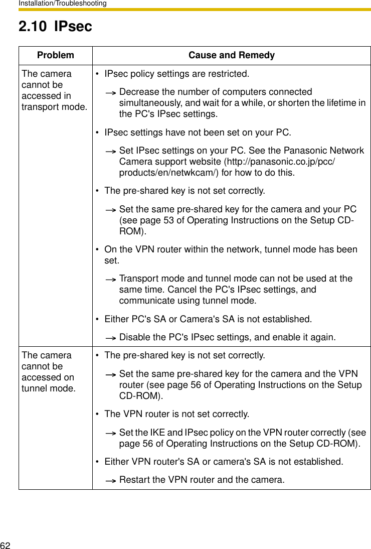
![Installation/Troubleshooting[For assistance, please call: 1-800-272-7033] 63E-mail or FTP transfer cannot be sent in transport mode.• The network settings are not set correctly.Cancel the IPsec settings on the server, PC and camera, and check that the camera images can be transferred. If they can be transferred, the IPsec settings were not set correctly. Set them correctly (see page 53 of Operating Instructions on the Setup CD-ROM).• The pre-shared key is not set correctly.Set the same pre-shared key for the camera, and server (see page 53 of Operating Instructions on the Setup CD-ROM).• There is a e-mail server or FTP server within the tunnel mode network.Transport mode and tunnel mode cannot be used at the same time. Cancel the e-mail server or FTP server's IPsec settings, and communicate using tunnel mode.• Either server's SA or camera's SA is not established.Restart the camera.Problem Cause and Remedy](https://usermanual.wiki/Panasonic-of-North-America/96NBB-HCM371A/User-Guide-488147-Page-63.png)
![Installation/Troubleshooting642.11 MiscellaneousProblem Cause and RemedyActiveX cannot be installed. • Security software disables the ActiveX installation.Close the security software, and install the ActiveX again.The firmware is not updated. • The firmware updating is not completed due to power off, network failure or other causes.Update the firmware again following the next procedures.*1See page 117 of the Operating Instructions on the Setup CD-ROM about updating firmware.Shortcut icon is not displayed in the My Network Places folder.•UPnPTM Windows component is not installed in Windows XP or Windows Me.Install UPnPTM Windows component in Windows XP or Windows Me (see page 146 of the Operating Instructions on the Setup CD-ROM).You cannot solve problems. • Call our customer call center at 1-800-272-7033.NoYesNoYesDisconnect the plug of the AC cord of the camera from the outlet, and reconnect it again.Enter the IP address on the web browser to access the camera.Is the Top page displayed?Is the version updated?Access the Setup page and click [Status]. Check the firmware version on the Status page.Update the firmware*1.The firmware update is completed.](https://usermanual.wiki/Panasonic-of-North-America/96NBB-HCM371A/User-Guide-488147-Page-64.png)
![Installation/Troubleshooting[For assistance, please call: 1-800-272-7033] 65Memo](https://usermanual.wiki/Panasonic-of-North-America/96NBB-HCM371A/User-Guide-488147-Page-65.png)