Panasonic of North America 96NBB-HCM371A 802.11b/g Wireless Camera Transmitter User Manual BBHCM371A IT
Panasonic Corporation of North America 802.11b/g Wireless Camera Transmitter BBHCM371A IT
User Manual
Installation/Troubleshooting
Please read this manual before using and save this manual for future reference.
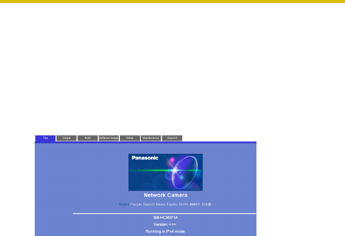
Network Camera
Panasonic Network Camera Website: http://www.panasonic.com/netcam
for customers in the USA or Puerto Rico
Model No.
BB-HCM371A

Installation/Troubleshooting
2
Introduction
How to Use This Documentation
The camera includes the following 2 manual types.
•Installation/Troubleshooting (This manual)
Installation/Troubleshooting provides explanations for accessories included
with the camera, the initial configuration, and troubleshooting tips. The
Installation/Troubleshooting helps you to easily configure the camera.
•Operating Instructions (Included on the Setup CD-ROM)
Operating Instructions explains about operations, settings, features and the
cleaning method when using the camera.
Abbreviations
• UPnP is the abbreviation for Universal Plug and Play.
• "Network Camera" is called "Camera" in this Installation/Troubleshooting.
Trademarks
• Adobe, Acrobat and Reader are either registered trademarks or trademarks of
Adobe Systems Incorporated in the United States and/or other countries.
• Ethernet is either a registered trademark or a trademark of Xerox Corporation
in the United States and/or other countries.
• Microsoft, Windows and ActiveX are either registered trademarks or
trademarks of Microsoft Corporation in the United States and/or other
countries.
• Pentium is a trademark or registered trademark of Intel Corporation or its
subsidiaries in the United States and other countries.
• SD mark is a trademark of the SD Card Association.
• Screen shots reprinted with permission from Microsoft Corporation.
• All other trademarks identified herein are the property of their respective
owners.

Installation/Troubleshooting
[For assistance, please call: 1-800-272-7033] 3
System Requirements for your PC
Your PC (Personal Computer) and network must meet the following technical
specifications for the camera to work properly.
For IPv4 Connection
Item Description
Operating
System Microsoft® Windows® XP, Microsoft® Windows® 2000
Microsoft® Windows® Me, Microsoft® Windows® 98SE
CPU •For viewing single camera
Pentium® III (800 MHz or greater is recommended.)
•For viewing multiple cameras
Pentium 4 (1.8 GHz or greater is recommended.)
Protocol TCP/IP protocol (HTTP, TCP, UDP, IP, DNS, ARP, ICMP)
Interface 10/100 Mbps network card installed
Web Browser Internet Explorer 6.0 or later (Not included on the Setup CD-
ROM)
Audio Audio input/output feature (Microphone or speaker)

Installation/Troubleshooting
4
Note
See Panasonic Network Camera support website at
http://panasonic.co.jp/pcc/products/en/netwkcam/ for details about
network environment.
What is IPv6?
• IPv6 is short for "Internet Protocol Version 6".
• IPv6 was created to address the additional IP addresses that will be
needed as the Internet continues to expand.
• IPv6 is expected to gradually replace IPv4, with the 2 coexisting for a
number of years during a transition period.
• Though most ISPs (Internet Service Providers) do not yet support IPv6,
many local networks already use it. When your ISP supports IPv6, your
Panasonic Network Camera will be ready!
• For more information you wish to visit http://www.ipv6.org/.
For IPv6 Connection
Item Description
Operating
System Microsoft® Windows® XP Service Pack 1 or later
CPU •For viewing single camera
Pentium III (800 MHz or greater is recommended.)
•For viewing multiple cameras
Pentium 4 (1.8 GHz or greater is recommended.)
Protocol TCP/IP protocol (HTTP, TCP, UDP, IP, DNS, ICMPv6, NDP)
Interface 10/100 Mbps network card installed
Web Browser Internet Explorer 6.0 or later (Not included on the Setup CD-
ROM)
Audio Audio input/output feature (Microphone or speaker)

Installation/Troubleshooting
[For assistance, please call: 1-800-272-7033] 5
Table of Contents
1 Before Using..................................................................7
1.1 IMPORTANT SAFETY INSTRUCTIONS........................................ 7
1.1.1 FCC and Other Information ....................................................................... 8
1.1.2 Security Cautions .................................................................................... 10
1.1.3 User Name and Password Protection...................................................... 10
1.2 Included Accessories................................................................... 11
1.3 Camera Feature Locations........................................................... 12
1.3.1 Front View................................................................................................ 12
1.3.2 Side View................................................................................................. 13
1.3.3 Bottom View ............................................................................................ 13
1.3.4 Rear View................................................................................................ 14
1.4 Connecting the Camera to Your Router ....................................... 15
1.5 Setting up the Camera to View on the LAN ................................. 17
1.6 Setting up Internet Access to the Camera ................................... 23
1.7 Confirming the Wireless LAN Setup ............................................ 27
1.8 Viewnetcam.com Service (IPv4/IPv6)..........................................28
1.9
Connecting the Camera to a Router Supporting UPnP™ (IPv4 Only).30
1.10 Connecting the Camera to a Router Not Supporting UPnP™ (IPv4
Only) ............................................................................................ 31
1.11 Setting up the Camera Using the MAC Address on the Setup
Program ....................................................................................... 32
1.12 Confirming the Camera Image..................................................... 35
1.13 Using the SD Memory Card......................................................... 38
1.14 Installing the Camera ................................................................... 39
1.14.1 Wiring the Camera................................................................................... 40
1.14.2 Mounting the Camera.............................................................................. 43
2 Troubleshooting ..........................................................47
2.1 Indicator Error Codes................................................................... 47
2.2 Camera Setup Difficulties............................................................. 49
2.3 About Wireless Communication................................................... 51
2.4 Camera Image/Page Display .......................................................52
2.5 Operation Bar............................................................................... 56

Installation/Troubleshooting
6
2.6 Audio Problems............................................................................ 57
2.7 Image Buffer/Image Transfer........................................................ 60
2.8 SD Memory Recording ................................................................ 61
2.9 IPv6.............................................................................................. 61
2.10 IPsec............................................................................................ 62
2.11 Miscellaneous .............................................................................. 64

Installation/Troubleshooting
[For assistance, please call: 1-800-272-7033] 7
1 Before Using
1.1 IMPORTANT SAFETY INSTRUCTIONS
When using this unit, basic safety precautions should always be followed to reduce
the risk of fire, electric shock, or personal injury.
1. Read and understand all instructions.
2. Keep these instructions.
3. Heed all warnings.
4. Follow all instructions.
5. After taking away the sand or the dust on the lens cover, wipe the lens cover
with a dry cloth.
6. Do not block any ventilation openings. Install in accordance with the
manufacturer's instructions.
7. Do not install near any heat sources such as radiators, heat registers, stoves,
or other devices (including amplifiers) that produce heat.
8. Protect the AC adaptor cord and AC cord from being walked on or pinched
particularly at plugs, convenience receptacles, and the point where they exit
from the unit.
9. The AC cord is used as the main disconnect device, ensure that the socket-
outlet is located/installed near the equipment and is easily accessible.
10.Only use attachments/accessories such as stand specified by the
manufacturer.
11.Do not touch the unit or the AC adaptor cord and AC cord during lightning
storms.
12.Unplug the unit when unused for long periods of time.
13.Refer all servicing to qualified service personnel. Servicing is required when
the unit has been damaged in any way, such as the AC adaptor, AC cord or
plug is damaged, the unit does not operate normally, or has been dropped.
14.The attached AC adaptor and AC cord is intended for indoor use only. Both AC
adaptor and AC cord must be waterproofed for outside use.
15.Keep the SD memory card (customer-provided) out of reach of children to
prevent swallowing.
SAVE THESE INSTRUCTIONS

Installation/Troubleshooting
8
1.1.1 FCC and Other Information
This equipment has been tested and found to comply with the limits for a Class B
digital device, pursuant to Part 15 of the FCC Rules. These limits are designed to
provide reasonable protection against harmful interference in a residential
installation. This equipment generates, uses and can radiate radio frequency
energy and, if not installed and used in accordance with the instructions, may
cause harmful interference to radio communications. However, there is no
guarantee that interference will not occur in a particular installation. If this
equipment does cause harmful interference to radio or television reception, which
can be determined by turning the equipment off and on, the user is encouraged to
try to correct the interference by one or more of the following measures:
• Reorient or relocate the receiving antenna.
• Increase the separation between the equipment and receiver.
• Connect the equipment into an outlet on a circuit different from that to which
the receiver is connected.
• Consult the dealer or an experienced radio/TV technician for help.
Some wireless Cameras operate at frequencies that may cause interference to
nearby TVs and VCRs. To minimize or prevent such interference, the base of the
wireless Camera should not be placed near or on top of a TV or VCR. If
interference is experienced, move the wireless Camera further away from the TV
or VCR. This will often reduce or eliminate interference. Operating near 2.4 GHz
electrical appliances may cause interference. Move away from the electrical
appliances.
Environment:
Do not install the camera where the temperature is less than -20 °C (+42 °F) or
greater than +50 °C (+122 °F). Allow 10 cm (4 inches) clearance around the unit
for proper ventilation. Avoid excessive smoke, dust, mechanical vibration, shock,
or direct sunlight.
Routine care:
Wipe the unit with a soft cloth. Do not use benzine, thinner, or any abrasive powder.
When you leave the unit unused for a long period of time, disconnect the power
cord from the outlet.
If you have any problems:
Consult an authorized Panasonic Factory Service Center.

Installation/Troubleshooting
[For assistance, please call: 1-800-272-7033] 9
FCC RF Exposure Warning
• To comply with FCC RF exposure requirements in uncontrolled environment:
• This equipment must be installed and operated in accordance with
provided instructions and a minimum 20 cm (8 inches) spacing must be
provided between antenna and all person's body (excluding extremities of
hands, wrist and feet) during wireless modes of operation.
• This transmitter must not be co-located or operated in conjunction with
any other antenna or transmitter.
•Medical
Consult the manufacturer of any personal medical devices, such as
pacemakers, to determine if they are adequately shielded from external RF
(radio frequency) energy. (The unit operates in the frequency range of 2.412
GHz to 2.462 GHz, and the power output level is 0.14 watts.) Do not use the unit
in health care facilities if any regulations posted in the area instruct you not to
do so. Hospitals or health care facilities may be using equipment that could be
sensitive to external RF (radio frequency) energy.
• Any changes or modifications not expressly approved by the party responsible
for compliance could void the user's authority to operate this device.
Audio and Video Recording Notice
PLEASE NOTE that under certain circumstances, audio/video recording may be
PROHIBITED by law. This device should be used only in compliance with all
applicable federal, state and local statutes.
No responsibility will be taken by our company with respect to consequences
resulting from the use, damage or both of the camera.

Installation/Troubleshooting
10
1.1.2 Security Cautions
When using this product, take appropriate measures to avoid the following security
breaches.
• Leaks of private information via this product
• Illegal use of this product by a third party
• Interference or suspension of the use of this product by a third party
Take the following measures to avoid security breaches:
• To prevent illegal access, keep the update firmware (If you do not have the
latest version of firmware, this can lead to blocked access or information
leaks).
• You are responsible for the security settings, such as user name and
password, to access this product. This information should not be made
available to any third parties outside the user group.
• Mount the camera where the camera will not be stolen.
• You are responsible for this product's user information, such as videos, still
images and internet contents etc. This information should not be made
available to any third parties outside the user group.
• When sending this product to be repaired with a company not related to
Panasonic, make back-up copies of files, if necessary, and reset this product
to factory default.
• When transferring this product to another party, make back-up copies of files,
if necessary, and reset this product to factory default.
• Recorded files stored on the SD memory card can lead to private information
leaks. When sending this product to be repaired or transferring it to another
party, ensure that the SD memory card is removed.
• When disposing of this product, reset this product to factory default, or erase
information by means of electrical deletion or physical dismantlement.
Panasonic Communications Co., Ltd.
1.1.3 User Name and Password Protection
The use of a unique User Name and secret Password is an important tool that
will help limit unauthorized individuals from accessing the camera. If you
choose to disable this tool, and choose not to limit access by use of a User
Name and Password, this may result in access to the camera by
unauthorized individuals. (see page 75 of the Operating Instructions in the
Setup CD-ROM)
Installation/Troubleshooting
[For assistance, please call: 1-800-272-7033] 11
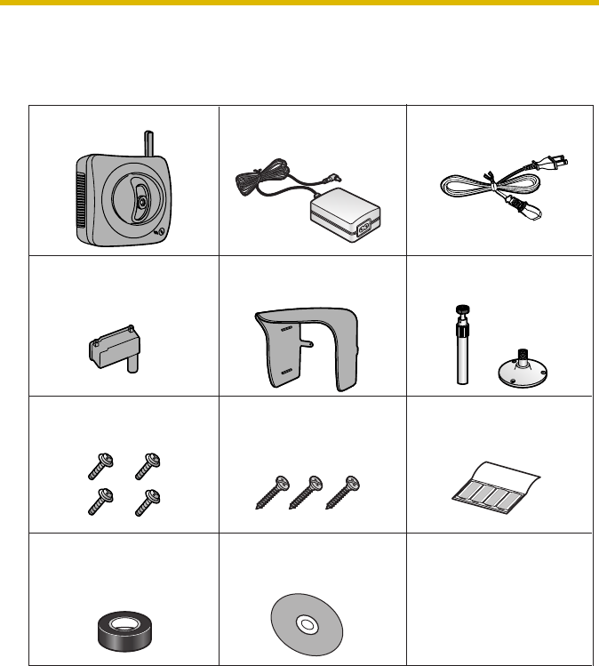
1.2 Included Accessories
The following items are provided with the camera. Additional pieces can be ordered
by calling 1-800-332-5368.
Main Unit—1 pc. AC Cord—1 pc.
Order No.: PSJA1069Z
Setup CD-ROM—1 pc.
Order No.: PSQX3242ZCD
Stand A (Left)—1 pc.
Stand B (Right)—1 pc.
Installation/
Troubleshooting
(This manual)—1 pc.
Screws for
Flexible Stand—3 pcs.
Order No.: PQHE5004Z
AC Adaptor—1 pc.
Order No.: PQLV202W
Sunshade—1 pc.
Order No.:
PSKV1051Z1
Putties—1 set (4 pcs.)
Order No.: PSHG1259Z
Self Bonding tape
—1 pc.
Order No.: PSHG1235Z
Connector Cover
—1 pc.
Order No.: PSKV1052Z1
Screws—4 pcs.
Order No.: XTN26+10GVW
Installation/Troubleshooting
12
1.3 Camera Feature Locations
1.3.1 Front View
Indicator Display
*1 The indicator turns orange if the camera is not connected to the LAN.
*2 The indicator blinks orange if the camera is not connected to the LAN.
*3 See page 48.
Lens Cover
Lens (0.5 m [about 20 inches]—Unlimited )
Indicator
The indicator color shows camera status.
Microphone
The microphone picks up audio around the camera.
(See page 29 of the Operating Instructions on the
Setup CD-ROM)
Power
on
Normal Operation*1
Updating Firmware
Getting IP address*2
Got IP address
Setting
Finished setting
Not on the LAN Orange blinking
Orange blinking
(The camera restarts after that.)
Pressing FACTORY
DEFAULT RESET button
Orange blinking Turning off
UPnPTM Failure Orange blinking (About a 2-second interval)
On the LAN
Using
DHCP
Automatic
Setup
Internal Failure Red blinking*3
Orange blinking Green
Green
Green
Green
Green blinking
Green blinking
Green blinking
Green blinking
Installation/Troubleshooting
[For assistance, please call: 1-800-272-7033] 13
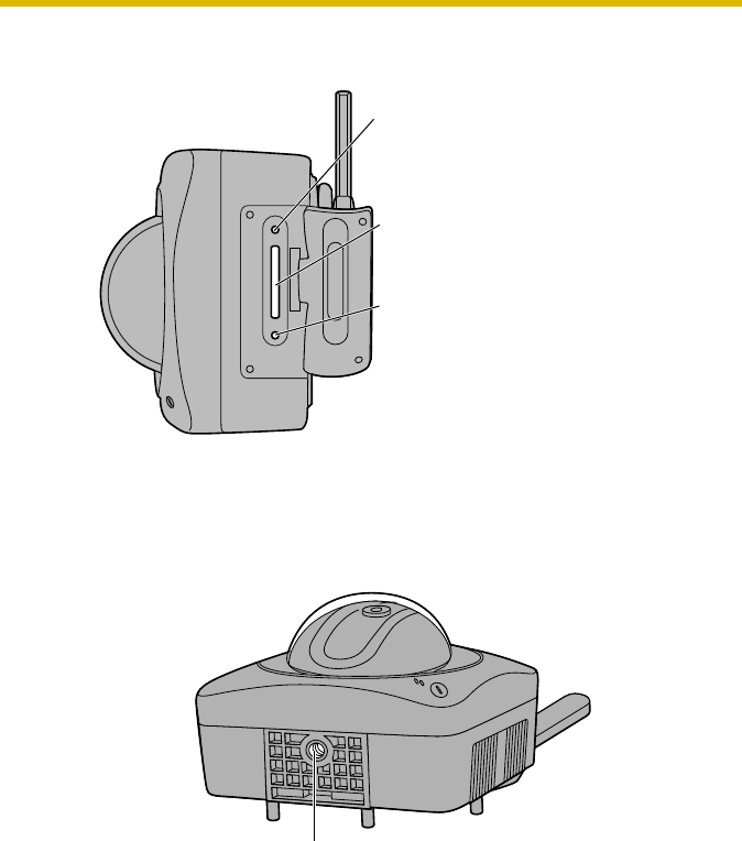
1.3.2 Side View
1.3.3 Bottom View
RESTART Button
Restarts the camera.
(see page 129 of the Operating
Instructions on the Setup CD-ROM).
SD Memory Card Slot
(See page 38)
FACTORY DEFAULT RESET Button
Resets settings to default (see page
128 of the Operating Instructions on
the Setup CD-ROM).
Stand/Tripod Mounting Hole (See page 43 and page 45)
Installation/Troubleshooting
14
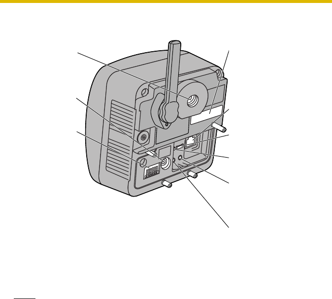
1.3.4 Rear View
Note
To listen to audio from the camera, an external amplified speaker (customer-
provided) must be connected to the camera. The connector used is a stereo
type, similar to that used by amplified PC speakers. Though the connector is
stereo, the audio is not.
Stand
Mounting Hole
(See page 44)
DC IN jack
(See page 16)
External I/O
(See page 126
of the
Operating
Instructions on
the Setup CD-
ROM))
MAC Address (see page
18) and Serial number (S/
N) is indicated on the
label.
Ethernet® (LAN) port
(See page 15)
Hook for Audio Cables
(See page 41)
Hook for Power Cord
(See page 41)
Audio Output Terminal
(See page 30 of the
Operating Instructions on
the Setup CD-ROM)
External Microphone
Input Terminal
(See page 30 of the
Operating Instructions on
the Setup CD-ROM)
Installation/Troubleshooting
[For assistance, please call: 1-800-272-7033] 15
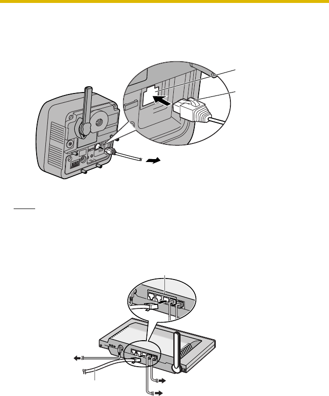
1.4 Connecting the Camera to Your Router
Connect the camera to your router with an Ethernet cable to set up the camera.
1. Connect the Ethernet cable (customer-provided) to the camera.
Note
These instructions assume your PC is already connected to the Internet and
your network includes a router.
2. Connect the Ethernet cable to your router.
Ethernet port
Ethernet cable
To your router
To a LAN port of your router
Ethernet cable
(Straight Cat5 cable)
(Customer-provided)
To the outlet
To your PC
To your modem
Installation/Troubleshooting
16
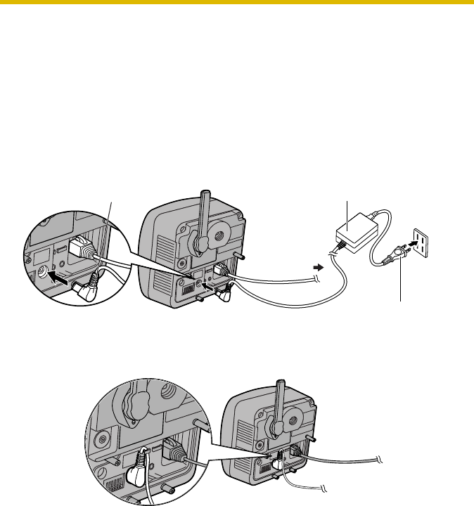
3. Connect the AC adaptor cord to the DC In jack, and plug the AC cord into the
outlet.
• The AC cord is used as the main disconnect device, ensure that the
socket-outlet is located/installed near the equipment and is easily
accessible.
• Use only specified Panasonic AC adaptor PQLV202 (Order No.
PQLV202W).
• If the indicator does not light green, see page 47 and page 48.
• A noise can be heard during pan/tilt operation. This is normal.
4. Hook the AC adaptor cord to the Hook for Power Cord.
AC adaptor
AC adaptor cord
To Router
AC cord
Installation/Troubleshooting
[For assistance, please call: 1-800-272-7033] 17
1.5 Setting up the Camera to View on the LAN
Setup CD-ROM allows you to easily set up the camera.
Notes
• To avoid any possible problems, temporarily disable any firewall or
antivirus software.
• This procedure explains installation of the camera on the same network
that your PC is part of.
• Before proceeding, close your web browser.
• See page 140 of the Operating Instructions on the Setup CD-ROM for
details.
• To set the Wireless Configuration, the wireless LAN settings of your
router—SSID, communication mode and encryption etc.—are required.
(See your wireless router's manual for your reference to the wireless LAN
settings.)
• When there are some cameras or PCs that are communicating wirelessly,
the IP addresses may overlaps and the camera may not be able to
communicate. See page "" of the Operating Instructions on the Setup CD-
ROM.
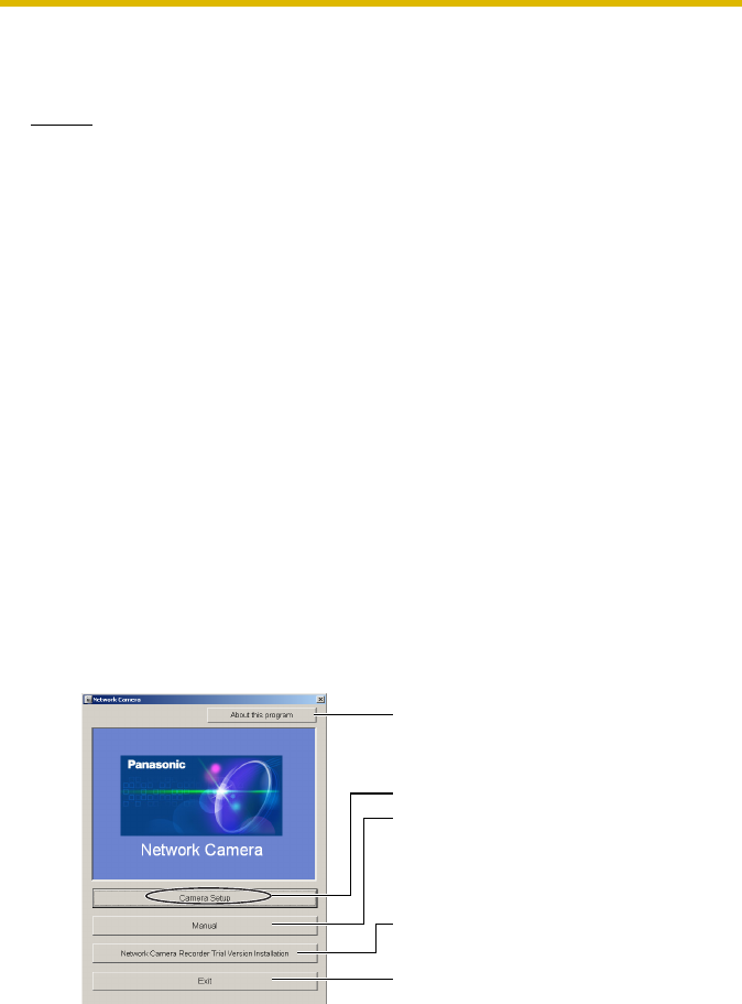
1. Insert the Setup CD-ROM into the CD-ROM drive of the PC.
• The window is automatically displayed.
(If the Network Camera Setup window is not displayed automatically,
double-click "Setup.exe" file on the Setup CD-ROM.)
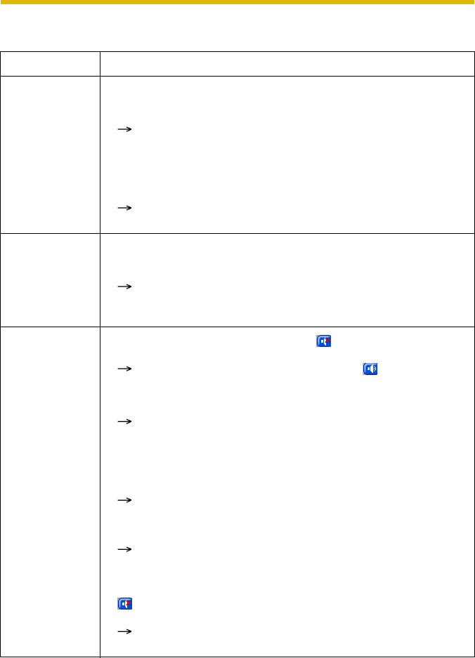
2. Click [Camera Setup].
Displays version information
about this program.
Sets up the camera.
Displays the camera manuals.
If your PC does not have Adobe®
Acrobat® Reader®, install it from
the Adobe Reader website.
Installs Network Camera
Recorder trial version.
Closes the Setup Program.
Installation/Troubleshooting
18
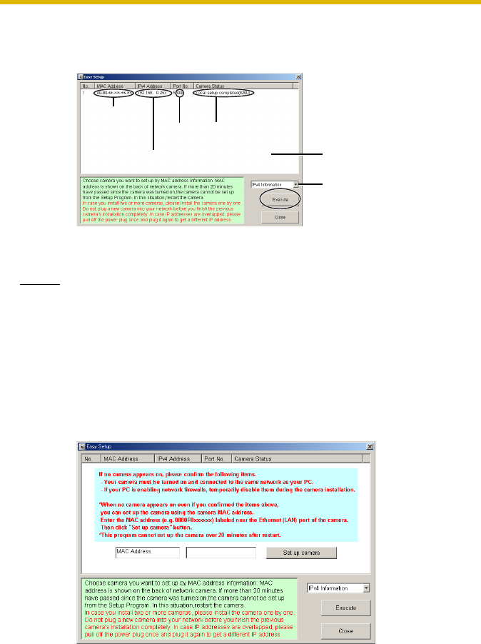
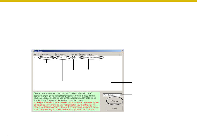
3. Select the camera to set up and click [Execute].
• This program searches for the cameras that are connected to the router
and displays the MAC Addresses, IP addresses and Port Numbers.
• The MAC Address on the rear side (see page 14) of the camera shows
which camera you select on the Camera List window.
Notes
• If more than 20 minutes have passed since the camera was turned on, the
camera cannot be set up from the Setup Program. In this situation,
disconnect the AC cord from the outlet, and reconnect it again.
• The Setup Program may not list any cameras due to your firewall or
antivirus software settings on your PC. If you cannot disable your firewall
or antivirus software, you can set up the camera entering the camera MAC
address on the following window. The camera's MAC address can be
found on the label affixed to the back of each camera. See page 32 for
details.
Camera
Status Camera
List window
Displays IPv4 or
IPv6 information.
Port
No.
MAC
Address
IP
Address
Installation/Troubleshooting
[For assistance, please call: 1-800-272-7033] 19
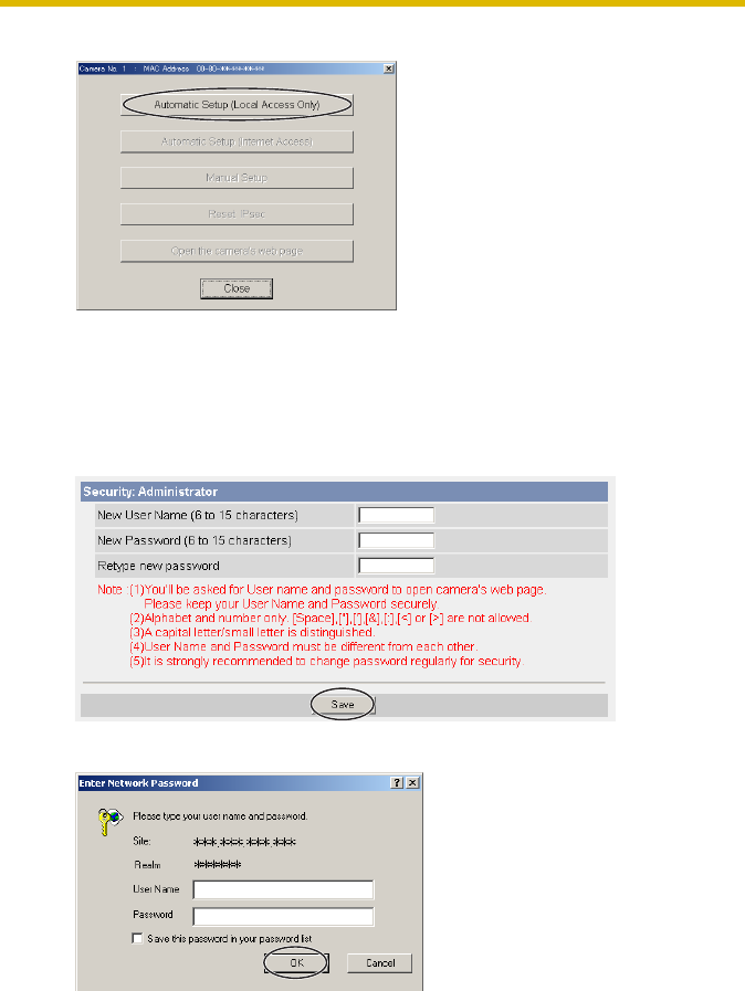
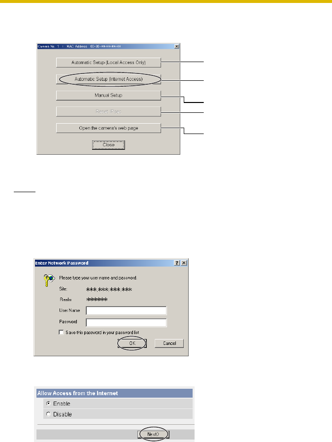
4. Click [Automatic Setup (Local Access Only)].
• For the first time installation or after pressing the FACTORY DEFAULT
RESET button, only [Automatic Setup (Local Access Only)] can be
selected. To set up the camera with Static or DHCP settings, after
performing the [Automatic Setup (Local Access Only)], run the Setup
Program again and select [Manual Setup].
5. Enter the user name and password you wish to use, and click [Save].
6. Enter the name and password that were entered above, and click [OK].
Installation/Troubleshooting
20
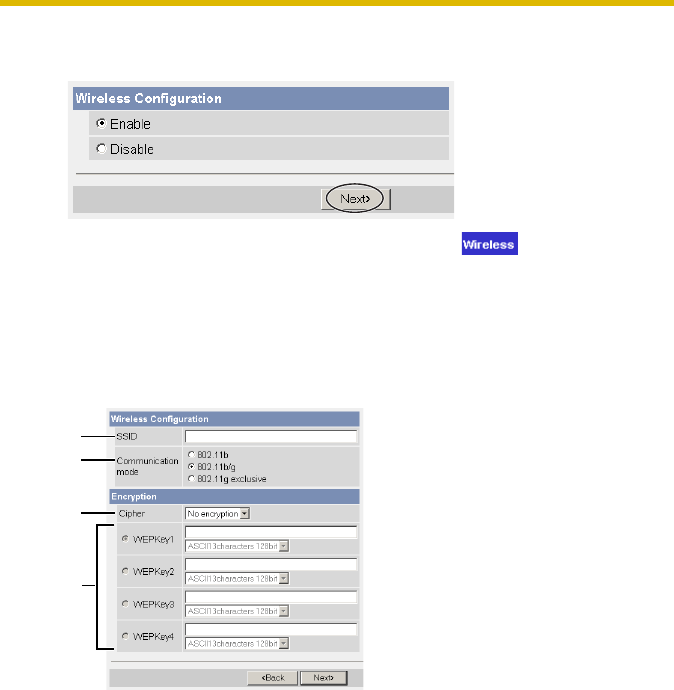
7. To set the Wireless Configuration, check [Enable] and click [Next>].
• When [Disable] was selected, skip to step 9.
• The Wireless Configuration can also be set at in the Setup Page.
(See page "" of the Operating Instructions in the Setup CD-ROM.)
8. Set the Wireless Configuration according to the wireless settings of the router
and click [Next>].
• For more information about wireless setting, see
http://panasonic.co.jp/pcc/products/en/netwkcam/technic/wireless/
cam_set.html
1. Set the SSID.
Set the name of the wireless network.
2. Select the Communication mode.
They are IEEE Communication modes. Select the same Communication
mode as that of the router to which the camera is connected.
802.11b (IEEE802.11b) : Only 802.11b wireless router can
be connected.
802.11b/g (IEEE802.11g) : Either 802.11b or 802.11g router
can be connected.
802.11g exclusive
(IEEE802.11g) : Only 802.11g router can be
connected.
1
2
3
4
Installation/Troubleshooting
[For assistance, please call: 1-800-272-7033] 21
3. Select encrypting or not encrypting.
Selecting WEP can encrypt data within the wireless LAN.
4. Set the WEPKey1–4.
Selecting [WEP] at Cipher enables you to set WEPKey1–4. One or all of
the four keys can be set. Check the same key number as set to the router,
and set the same key as at the router.
<Example>
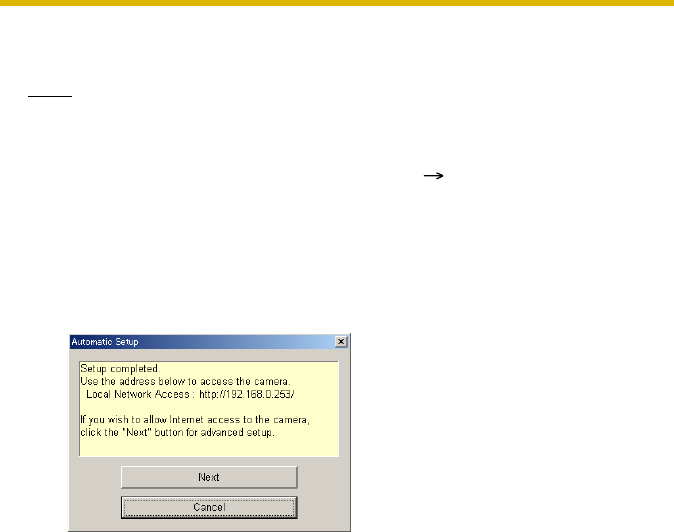
9. When the Single Camera page is displayed, the setup is completed.
• When Security Warning window is displayed, click [Yes]. (See page 37)
WEP : Encrypting (setting WEP) makes it difficult for
unauthorized users to read data within the wireless
LAN, even if they can receive it. To encrypt data, set
the same encryption key to every terminal within the
wireless LAN. There are 3 kinds of encryption key:
64 bit, 128 bit and 152 bit. Security level of
encryption increases in order of length as follows: 64
bit, 128 bit and 152 bit.
No encryption : select when not using encryption.
:The entered WEPKey will be displayed as " "s
regardless of the key type selected.
HEX, 10 characters 64 bit : 012345abcd
HEX, 26 characters 128 bit : 0123456789abcdef012345abcd
HEX, 32 characters 152 bit : 0123456789abcdef0123456789abcdef
ASCII 5 characters 64 bit : 012yz
ASCII 13 characters 128 bit : 0123456uvwxyz
ASCII 16 characters 152 bit : 0123456789uvwxyz
Installation/Troubleshooting
22
• When having set the wireless configuration, follow "1.7 Confirming the
Wireless LAN Setup" on page 27.
Note
To insure that the most current image is displayed, Internet Explorer should be
configured as follows. This will not have any negative result on normal use.
To enable Internet access to the camera
Click [Next] to set up the Internet access to the camera and go to step 3 on the
page 24.
• If you do not allow the Internet access, click [Cancel], and go to page 35
to confirm the camera image.
1. While viewing any website, Click [Tools] [Internet Options].
2. In the section "Temporary Internet Files", click [Settings] and check
[Every visit to the page].
Installation/Troubleshooting
[For assistance, please call: 1-800-272-7033] 23
1.6 Setting up Internet Access to the Camera
1. Display the Camera List window (see page 17—page 18).
2. Select the camera to set up and click [Execute].
• This program searches for the cameras that are connected to the router
and displays the MAC Addresses, IP addresses and Port Numbers.
• The MAC Address on the rear side (see page 14) of the camera shows
which camera you select on the Camera List window.
Note
If more than 20 minutes have passed since the camera was turned on, the
camera cannot be set up from the Setup Program. In this situation, restart the
camera.
Camera
Status Camera
List window
Displays IPv4 or
IPv6 information.
Port
No.
MAC
Address
IP
Address
Installation/Troubleshooting
24
3. Click [Automatic Setup (Internet Access)].
Note
In order for Internet access to be properly enabled, your routers UPnPTM
feature should be enabled. Most router manufacturers disable this feature. See
http://panasonic.co.jp/pcc/products/en/netwkcam/technic/rtr_setup for
more information.
4. Enter the user name and password that were set, and click [OK].
5. To enable Internet access, select [Enable]. Choose [Disable] if you wish to
restrict access to your local network.
• If you use a router not supporting UPnPTM, click [Disable]. If you select
[Disable], skip to step 9.
Sets up the camera to view on
the LAN.
Sets up the Internet access to
the camera.
Manually sets up the camera.
Disables IPsec. If disabled, the
button is displayed gray.
Displays the Setup page (see
page 39 of the Operating
Instructions on the Setup CD-
ROM).

Installation/Troubleshooting
[For assistance, please call: 1-800-272-7033] 25
6. To register with the "Viewnetcam.com FREE DDNS service", check [Register
with Viewnetcam.com] and click [Next].
Viewnetcam.com FREE DDNS service
See page 28 for Viewnetcam.com information. For detailed information,
access at http://www.viewnetcam.com.
• If you have multiple cameras, you can use Viewnetcam.com service
registering it only for a camera.
• If you select [Disable], skip to step 9.
7. The Enter Network Password window is displayed, and enter the user name
and password that were set, and click [OK].
8. After a while, the "Viewnetcam.com FREE DDNS service" website is
displayed. Follow the displayed instructions for registration.
• If the message "Failed to configure the router's Port Forwarding by UPnP"
is displayed, your router may not support UPnPTM or UPnPTM is not
enabled. Enable your router's UPnPTM or set Port Forwarding manually
following the router's manual and try Automatic Setup again. For more
information about setting up a router, refer to the Panasonic Network
Camera support website at http://panasonic.co.jp/pcc/products/en/
netwkcam/technic/rtr_setup.
• If the message "Failed to register with Viewnetcam.com." is displayed,
confirm that the router is connected to the Internet.
Installation/Troubleshooting
26
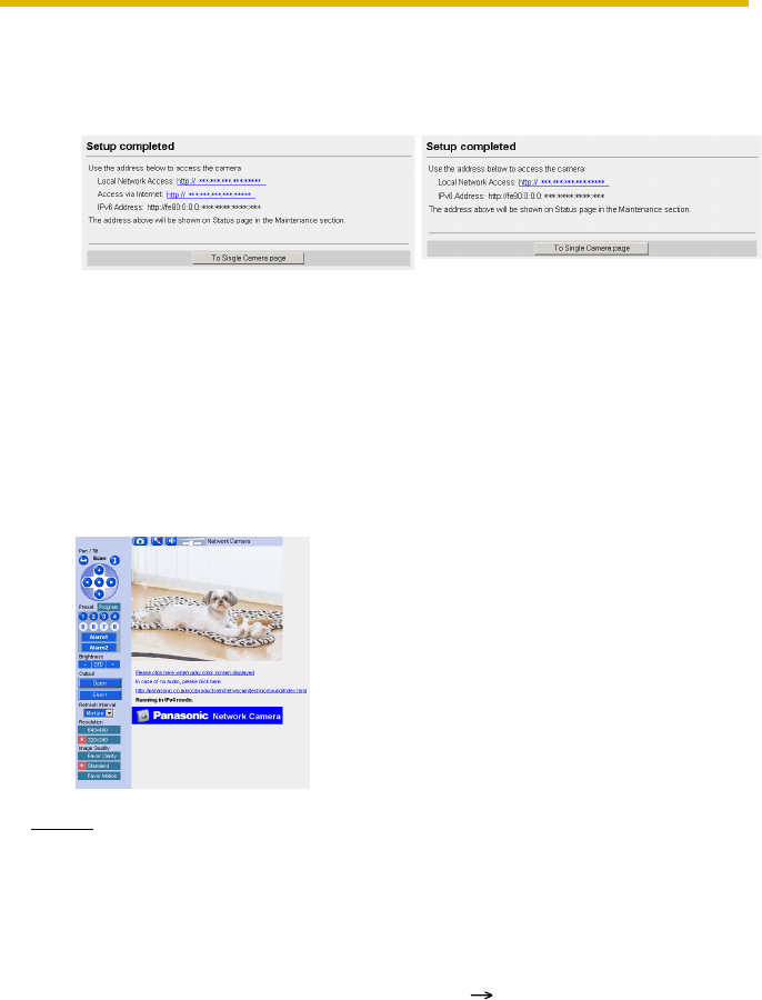
9. When "Setup complete" is displayed, and click [To Single Camera page].
• The port number must be specified at the end of camera URL.
Using port 80:
http://(Cameraname).viewnetcam.com
or http://IP Address
Using any other port:
http://(Cameraname).viewnetcam.com:Port Number
or http://IP Address:Port Number
10.When the Single Camera page is displayed, the setup is completed.
Notes
• The banner is displayed only when Internet access is allowed on the
camera.
• To insure that the most current image is displayed, Internet Explorer
should be configured as follows. This will not have any negative result on
normal use.
•When [Enable] was selected at
step 5 •When [Disable] was selected
at step 5
1. While viewing any website, Click [Tools] [Internet Options].
2. In the section "Temporary Internet Files", click [Settings] and check
[Every visit to the page].
Installation/Troubleshooting
[For assistance, please call: 1-800-272-7033] 27
1.7 Confirming the Wireless LAN Setup
After setting each item for the wireless LAN, confirm that the camera works
correctly.
1. Start up the web browser on the PC.
2. Enter "http://IP address (or URL):Port No." in the address field and press
[Enter].
(When port number is 80 (default), you do not need to enter port number.)
3. When the following Top Page is displayed, the wireless LAN setup is
successful.
• If the Top Page was not displayed, the settings for the camera are not
identical with those for the router. Check the settings by using wired
connection.
If the settings are correct and you use a proxy server, set the web browser
not to access the proxy server.
If the Top Page is not displayed even after trying these methods, contact
the retailer.
• It takes about 1 minute for the new settings to be effective.
• It is not possible to access the camera simultaneously by both wired and
wireless connection.
Installation/Troubleshooting
28
1.8 Viewnetcam.com Service (IPv4/IPv6)
Viewnetcam.com is the free dynamic DNS (DDNS) service offered by Panasonic.
It allows you to assign an easy-to-remember name to your camera, similar to your
favorite website. Many ISPs use a "dynamic" IP address that reassigns a new IP
address to your account monthly, weekly or sometimes each time you log on.
Viewnetcam.com automatically tracks these changes and associates them to a
name you choose.
• Domain Name Service such as Viewnetcam.com
The camera can be accessed with a static domain name (e.g.
camera.viewnetcam.com), even if your ISP offers a dynamic global IP address.
Domain name service is required for IPv6 connection.
• Static IP Address Service offered by your ISP
The camera can be accessed with a static global IP address.
See the website at http://www.viewnetcam.com for details.
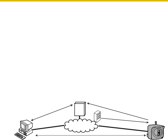
How the Viewnetcam.com service works
1. Your ISP assigns a global IP address dynamically to a router or a camera. The
IP address changes regularly. If you view the camera from the Internet, the
global IP address is required.
2. If you register with the Viewnetcam.com service, a unique domain name is
assigned to the camera. The camera automatically send your global IP
address to the Viewnetcam.com server, and the Viewnetcam.com server
manages Internet access comparing your registered domain name with a
global IP address.
3. The Viewnetcam.com server looks up the global IP address that matches to
your domain name, and automatically finds your camera.
4. You can access the camera with your domain name without considering the
dynamic global IP address.
Viewnetcam.com Server
Internet
Automatically registering
"camera.viewnetcam.com"
and the IP address.
ISP
From offices or
business trip Remote
shop
2.
Automatically obtaining the
current IP address from
"camera.viewnetcam.com".
3.
IP address changes.1.
Accessing the camera with the current IP address.4.

Installation/Troubleshooting
[For assistance, please call: 1-800-272-7033] 29
Notes
• Ask your ISP about what type of IP address you are using.
• Some ISPs assign you a local IP address. In this case, you cannot use the
Viewnetcam.com service. Ask you ISP about what type of IP address you are
using.
• If the camera is using a port number other than 80, the port number must be
specified at the end of the Viewnetcam URL. For example:
Using port 80: http://(Cameraname).viewnetcam.com
Using any other port: http://(Cameraname).viewnetcam.com:Port Number

Installation/Troubleshooting
30
1.9 Connecting the Camera to a Router
Supporting UPnP™ (IPv4 Only)
To allow access from the Internet with a router supporting UPnPTM, follow the
procedures shown in the Getting Started.
Notes
• In some routers, the UPnPTM feature is disabled by default. Enable your
router's UPnPTM feature following the router manual before you set up the
camera. See the Panasonic Network Camera support website at http://
panasonic.co.jp/pcc/products/en/netwkcam/technic/rtr_setup for
details.
• If the maximum idle time is set in PPPoE or PPTP connection with your
ISP, disable it on the router. See the router manual for details.
Installation/Troubleshooting
[For assistance, please call: 1-800-272-7033] 31
1.10 Connecting the Camera to a Router Not
Supporting UPnP™ (IPv4 Only)
To allow access from the Internet with a router not supporting UPnPTM, follow the
procedures below.
1. Select [Static] on the Network (IPv4) page.
2. Enable port forwarding on the router.
Using the IP address and port number note written on step 1-(3), enable port
forwarding on the router. See the router manual for how to enable port
forwarding.
3. Register with the Viewnetcam.com service.
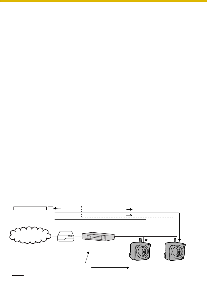
Port Forwarding feature*1 (IPv4 Only)
The port forwarding feature is required to allow access from the Internet with a
router not supporting UPnPTM. It exchanges a local IP address to a global one.
Each camera must be assigned a unique port number.
(1) Access the camera (see page 13 of the Operating Instructions on the
Setup CD-ROM).
(2) Click [Setup] tab at the top of the page.
(3) Select [Static] on the Network page.
• The Static IP Address Configuration page is displayed. Make a
note of the IP address and port number, since they are required to
enable port forwarding on the router.
(4) Click [Save] without changing the settings.
(5) Click [Restart].
*1 "Port forwarding" may be called "Address translation", "Static IP Masquerade", "Virtual server"
or "Port mapping" in other products.
Global IP address
of the router
vvv.xxx.yyy.zzz:80
vvv.xxx.yyy.zzz:81
vvv.xxx.yyy.zzz:80 192.168.0.253:80
vvv.xxx.yyy.zzz:81 192.168.0.252:81
Port No.
Port Forwarding feature
Local IP address
The IP addresses shown above may differ from those offered on your home network.
Note
192.168.0.1
192.168.0.252
Port No. 81 192.168.0.253
Port No. 80
Router
Modem
CATV
xDSL
Optical cable
Internet
Installation/Troubleshooting
32
1.11 Setting up the Camera Using the MAC
Address on the Setup Program
The Setup Program may not list any cameras due to your firewall or antivirus
software settings on your PC. If you cannot disable your firewall or antivirus
software, you can set up the camera using the camera MAC address as shown
below.
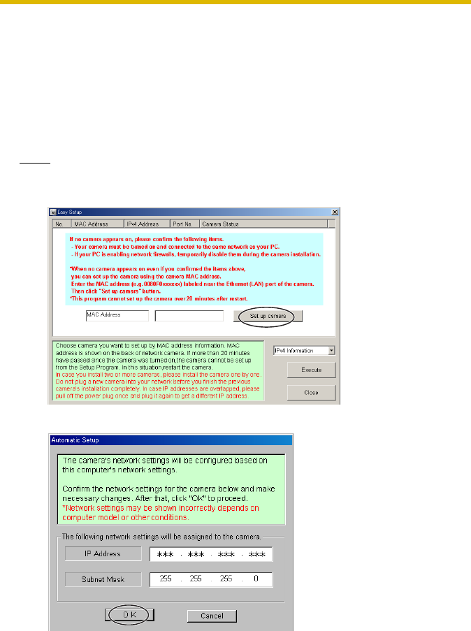
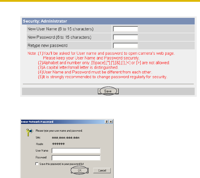
1. Enter the camera MAC address in the data field, and click [Set up camera].
Note
The cameras MAC address can be found on the sticker affixed to the back of
the camera (see page 14).
2. After confirming the network settings, click [OK].
• After about a minute, the Security: Administrator page is displayed.
Installation/Troubleshooting
[For assistance, please call: 1-800-272-7033] 33
3. Enter the user name and password, and click [Save].
4. The Enter Network Password window is displayed. Enter the user name and
password that were set, and click [OK].

Installation/Troubleshooting
34
5. When the Single Camera page is displayed, the setup is completed.
• If Security Warning window is displayed, click [Yes] (see page 37).
Notes
• See page 17 of the Operating Instructions on the Setup CD-ROM for the
Single Camera page.
• If you enable the Internet access to the camera, follow the procedures
below.
•When you are using a router supporting UPnPTM
•When you are using a router not supporting UPnPTM
Follow the procedures shown on page 31.
1. Enable the Auto Port Forwarding feature on the UPnP page (see
page 63 of the Operating Instructions on the Setup CD-ROM).
2. Register with the Viewnetcam.com service on the Viewnetcam.com
page (see page 65 of the Operating Instructions on the Setup CD-
ROM).
3. Confirm the Internet access to the camera (see page 35).
Installation/Troubleshooting
[For assistance, please call: 1-800-272-7033] 35
1.12 Confirming the Camera Image
1. Start up the web browser on your PC.
2. Enter "http://IPv4 Address (or URL):Port Number" on the address bar, and
press [Enter] on the keyboard.
• When port number is 80 (default), you do not need to enter port number.
See page 44 of the Operating Instructions on the Setup CD-ROM for
details about port number.
• For IPv6 connection, see page 15 and page 16 of the Operating
Instructions on the Setup CD-ROM and prepare the requirements. Enter
the "http://(IPv6-registered URL):Port Number" on the address bar.
• If the camera image is not displayed, see page 52.
3. The Enter Network Password window is displayed, and enter the user name
and password that were set, and click [OK].
Note
When [Permit access from guest users] is set on the Security: Administrator
page, authentication window will not be displayed.
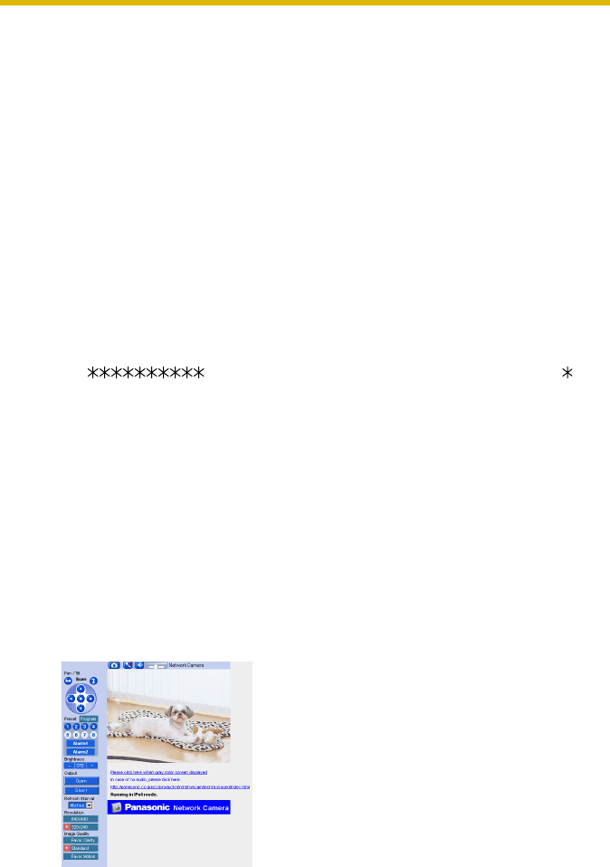
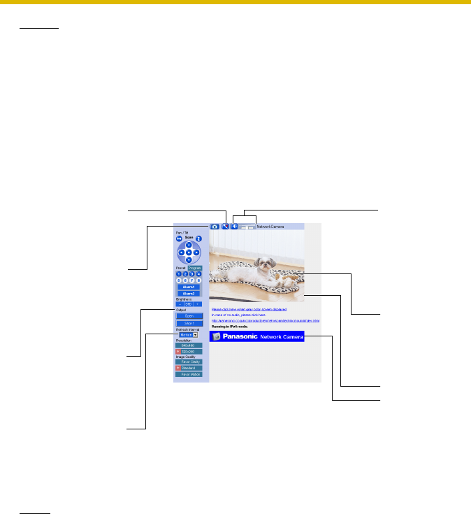
4. Click the following tabs to display each page.
ATo Single Camera page
(page 17 of Operating Instructions) BTo Multi-Camera page
(page 32 of Operating Instructions)
CTo Buffered Image page
(page 34 of Operating Instructions) DTo Setup page
(page 39 of Operating Instructions)
ETo Maintenance page
(page 114 of Operating Instructions) FTo Support page
(page 123 of Operating Instructions)
GTo log in to the camera
(page 78 of Operating Instructions)
A B C D E F G
Select a language
to display.
Displays IPv4, IPv6
or IPsec connection.
Version Number
Installation/Troubleshooting
36
Notes
• When users other than an administrator are accessing the camera,
[Setup] and [Maintenance] tab will not be displayed. Additionally, When
[Do not permit access from guest users] is set on the Security:
Administrator page, [Login] tab will not be displayed.
• If [View Multi-Camera page] or [View Buffered Image page] is not
permitted on the General User page, [Multi-Camera] or [Buffered Image]
tab will not be displayed.
5. Click [Single] tab on the above.
• When Security Warning window is displayed, click [Yes]. (See page 37)
Note
For IPv6 connection, see page 15 and page 16 of the Operating Instructions
on the Setup CD-ROM.
6. Close the web browser.
Talk Button
(see page 29 of
the Operating
Instructions)
Capture Image
Button
(see page 22 of
the Operating
Instructions)
Operation Bar
(see page 23 of
the Operating
Instructions)
Refresh Interval
(see page 23 of
the Operating
Instructions)
Listen Button
and
Adjustment
Bar
(see page 29 of
the Operating
Instructions)
Click to Center
(see page 21 of
the Operating
Instructions)
Camera Image
The banner is
displayed.
(see page 20 of
the Operating
Instructions)
Installation/Troubleshooting
[For assistance, please call: 1-800-272-7033] 37
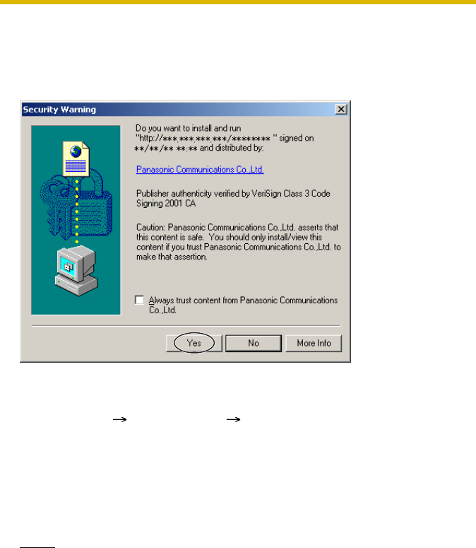
Security Warning window
To view a video (Motion JPEG) or to use audio feature, ActiveX® Controls must be
installed. When trying to display a video for the first time, Security Warning window
will be displayed. When using Windows 2000 or Windows XP, log in as an
administrator to install it.
If you cannot install ActiveX Controls or you cannot see the video in the
Internet Explorer
• Click [Tools] [Internet Options] [Security] tab and click [Custom level] on
the web browser.
(1) Check "Prompt" in "Download signed ActiveX Controls".
(2) Check "Enable" in "Run ActiveX Controls and plug-ins".
• ActiveX Controls can be installed from the file on the Setup CD-ROM.
(1) Restart the PC.
(2) Confirm that Internet Explorer is closed.
(3) Double-click"ocx\ActiveXInst.exe" on the Setup CD-ROM.
Notes
• Video may not be displayed quickly or audio may not be listened immediately.
Wait for a while.
• If you use a proxy server, set the web browser not to access the proxy server
(see page 143 of the Operating Instructions on the Setup CD-ROM).
• In some corporate network environments a firewall may be used for security
purposes. It is possible that this may prevent motion video from being
displayed. In this situation we suggest:
• Contact your network administrator.
• Try using regularly refreshed images.
Installation/Troubleshooting
38
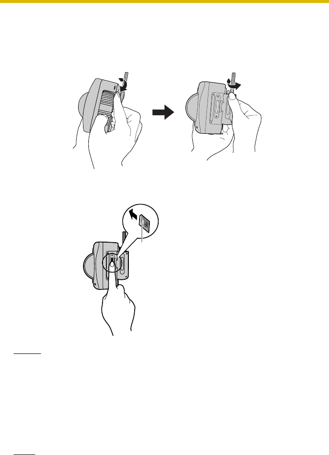
1.13 Using the SD Memory Card
The SD memory card (customer-provided) can store image data and replay them.
Follow the instructions below to insert the SD memory card into the camera.
1. Open the cover on the side of the camera.
2. Insert the SD memory card, and push with your finger until it clicks. Or push
the card lightly to remove.
Notes
• Ensure that recording has been stopped, before removing the SD memory
card. (see page 87 of Operating Instructions on the Setup CD-ROM) If the
SD memory card is removed while recording, the image file will most likely
become unreadable. In this case, format the SD memory card again.
(Files will be deleted.)
• Insert or remove the SD memory card after removing the sunshade.
3. Replace the cover firmly.
Note
Format the SD memory card, before you record the image data. (see page 86
of Operating Instructions on the Setup CD-ROM)
Place the card face
to the front.
PRO HIGH SPEED
LOCK
OCK

Installation/Troubleshooting
[For assistance, please call: 1-800-272-7033] 39
1.14 Installing the Camera
The camera has a splash resistant body. The splash resistant body allows the
camera to be used indoors and outdoors. Waterproof cabling is necessary for
outdoor mounting. Check the camera operation before installing (cabling and
mounting) the camera.
Notes
• Install the camera under eaves to protect it from direct sunlight. Prolonged
exposure to direct sunlight or halogen light may damage the CCD sensor.
• Use the sunshade in any conditions.
• Do not install the camera in the location where sea breezes may hit the
unit directly.
• Avoid laying Ethernet cable underground or stringing it in the air. Lightning
may cause serious damage to the camera or the connected devices.
• AC adaptor and AC cord are not waterproofed. Put them inside the
outdoor power equipment near the camera and protect them from the rain.
Ask the authorized electric wiring dealer.
• AC adaptor, AC cord and Ethernet cable should be waterproofed. Do the
waterproof electric wiring work.
• Do not expose the AC adaptor to the temperatures below -20 °C (-4 °F) or
above +50 °C (122 °F). AC adaptor cannot be operated under these
circumstances.
Installation/Troubleshooting
40
1.14.1 Wiring the Camera
Check the location where the camera should be installed. Select the proper cable
suited to the camera location. Consult an authorized wiring electrician for cabling.
The camera can be mounted in the following ways.
1. Put the cables through the connector cover (1.). Connect the DC plug of the
AC adaptor to the DC IN jack (2.) and Ethernet cable to the Ethernet port (3.).
Connect the AC plug of the AC cord to the outlet (4.).
• If you use External I/O, external speaker or external microphone, put the
cables through the connector cover.
Notes
• Confirm that the indicator lights green.
• Check the location of the camera, the type and the length of the Ethernet
cable (Max. 100 m [330 feet]). Use an Ethernet cable as short as possible
for outdoor use. Lightning may cause serious damage to the camera or the
connected devices.
Ethernet port
DC IN jack
External I/O
(1.)
Connector
Cover
AC adaptor
(4.)
Outlet
To Network
(2.) DC Plug
Ethernet cable
(3.)
Installation/Troubleshooting
[For assistance, please call: 1-800-272-7033] 41
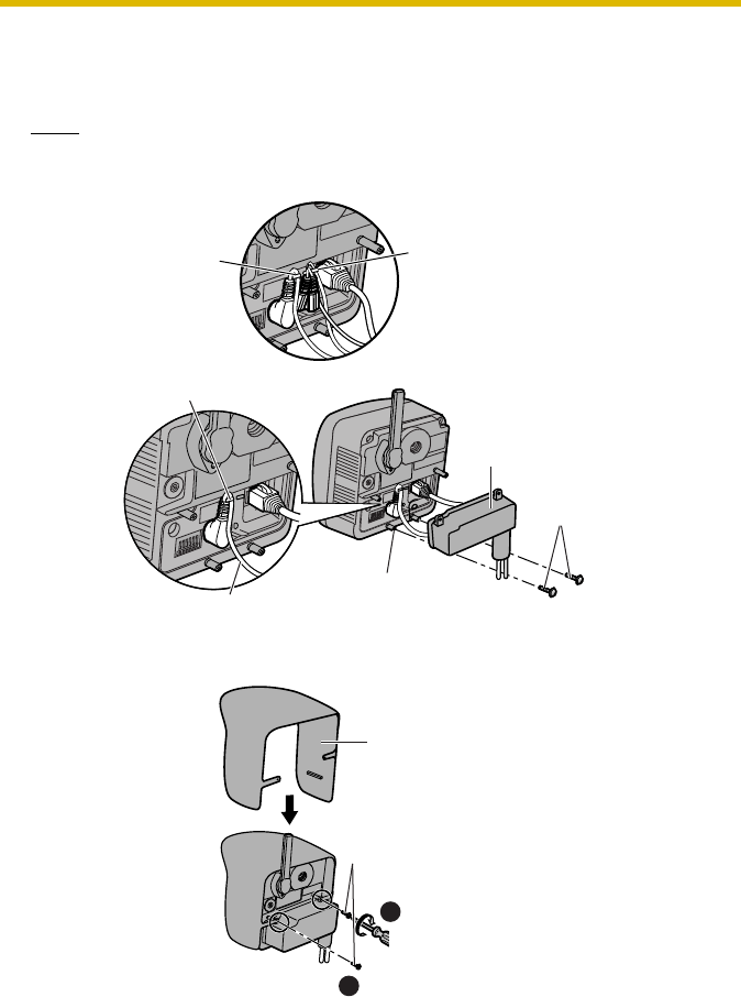
2. Thread the AC adaptor cord through the hook. Put the connector cover by
fastening the two screws in numerical order. The remaining screw hole on the
connector cover is used for attaching sunshade.
Note
When you mount the camera, always hook the AC adaptor cord and audio
cables to the hooks.
3. Attach the sunshade by fastening the two screws.
Hook for
Power Cord Hook for
Audio Cables
Connector cover
Screw
(accesories)
Screw hole
AC adaptor cord
Hook
3
Sunshade
(accessories)
Screw
(accessories)
4
Installation/Troubleshooting
42
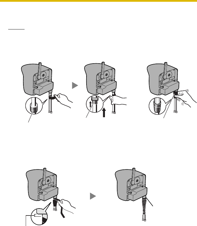
4. Roll up putty around the cables and fit them into the holes to prevent water
from getting inside the camera.
Notes
• Confirm the camera is functioning before puttying the cables. Putties and
self bonding tape cannot be used twice.
• Check the length and the type of the Ethernet cable before fixing with
putty.
5. Cover the putty by rolling.
• Self bonding tape is used to fix the cables in a mount. Keep at least 20 cm
(about 8 inches) of it for cable fixing.
6. Connect the Ethernet cable to the Ethernet port of hub, router and PC.
Push the putty
into the connector
cover.
Three putties Cover the connector cover
and cables with the last
putty, and fix the shape.
5–10 mm
(0.2–0.4 inches)
Do not cover
the ventilation hole.
Installation/Troubleshooting
[For assistance, please call: 1-800-272-7033] 43
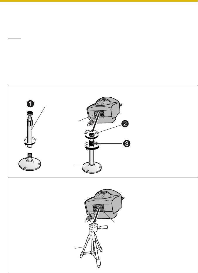
1.14.2 Mounting the Camera
Four mounting methods are shown in the following figures. Confirm the top and
bottom of the camera when mounting. Ask the authorized dealer for mounting.
Note
Mounting and cabling instructions described in this Installation/
Troubleshooting follow generally accepted guidelines suitable for residential
installations. In some areas, commercial and industrial installations are
regulated by local or state ordinances. For such installations, contact your local
building department or building inspector for more details.
Flexible Stand Mount
Tripod Mount
Stand/Tripod
Mounting Hole
Flexible
Stand
Screw the threaded mount
into the stand/tripod
mounting hole.
Fit Stand A with Stand B.
Turn the grip firmly.
Stand/Tripod
Mounting Hole
Tripod
Installation/Troubleshooting
44
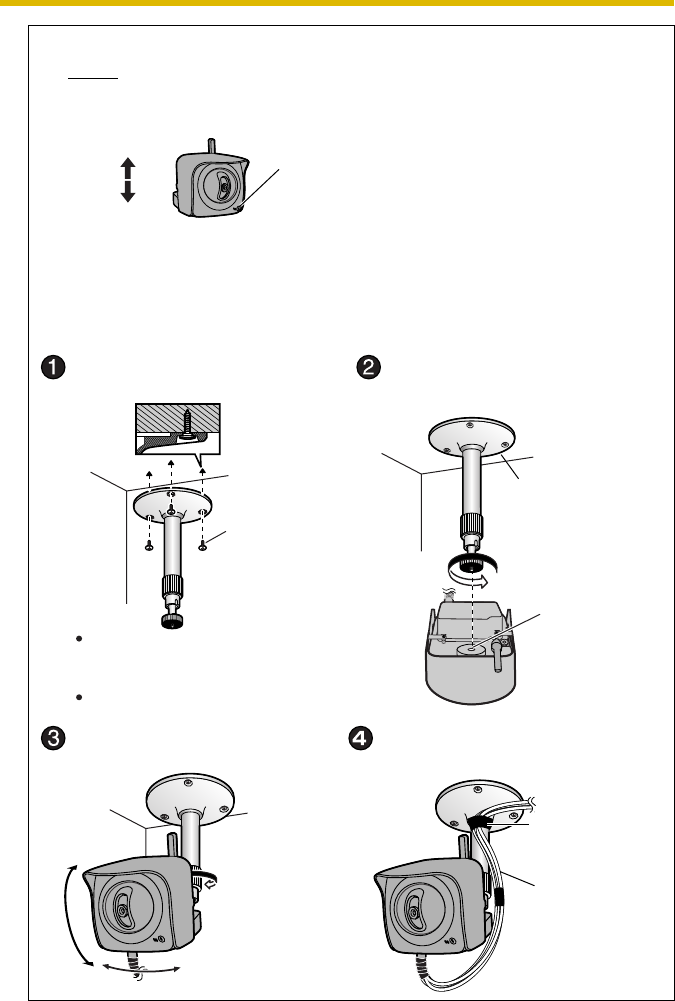
Ceiling Mount
Notes
• Do not mount the camera upside down. The image may be displayed
upside down.
• When mounting, we suggest using the hardware we provide. Mounting
in any other manner may cause the camera to fall, causing personal
injury or damage to the camera.
• To reduce the load on the mounting hardware, dress the cables neatly
and secure with tape.
Make sure the indicator is
always in the lower right
corner.
Top
Bottom
Caulk around
flexible stand
if necessary.
Waterproof
the rest
of the cable.
Mount the flexible stand firmly to the
ceiling with the three screws (accessories).
Attach the camera screwing the
threaded mount into the stand
mounting hole.
Screw
Adjust the camera position
and secure the flexible stand firmly.
Roll up the cables and flexible stand
with the self bonding tape (accessories).
Do not mount the camera on a soft
material. The camera may fall and
break down.
Use appropriate screws suited for
the material of the ceiling.
Stand
Mounting
Hole
Self bonding
tape
Installation/Troubleshooting
[For assistance, please call: 1-800-272-7033] 45
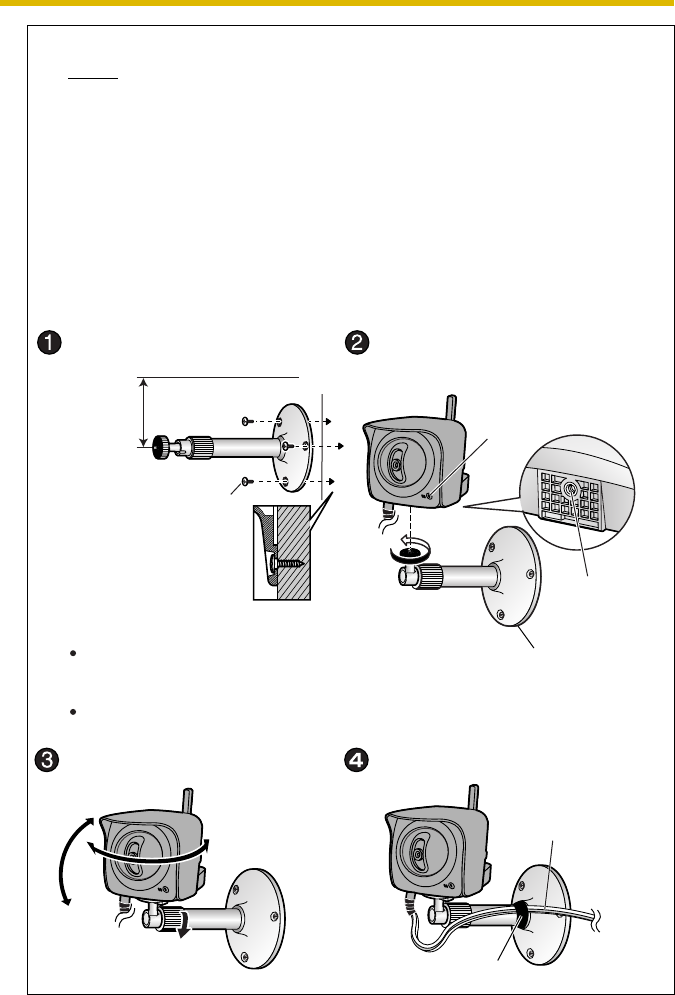
Wall Mount
Notes
• Drive mounting screws into the wall. Be careful to avoid touching any
metalwork (metal/wire laths etc.), conduits or electrical cables buried in
the wall.
• Do not mount the camera upside down. The image may be displayed
upside down.
• When mounting, we suggest using the hardware we provide. Mounting
in any other manner may cause the camera to fall, causing personal
injury or damage to the camera.
• To reduce the load on the mounting hardware, dress the cables neatly
and secure with tape.
165 mm
(6.5 inches)
Self bonding tape
Waterproof the rest
of the cable.
Screw
Mount the flexible stand firmly to the
wall with the three screws (accessories).
Attach the camera screwing the
threaded mount into the stand/tripod
mounting hole.
Adjust the camera position
and secure the flexible stand firmly.
Roll up the cables and flexible stand with
the self bonding tape (accessories).
Do not mount the camera on a soft
material. The camera may fall and
break down.
Use appropriate screws suited for
the material of the ceiling.
Caulk around
flexible stand
if necessary.
Stand/Tripod
Mounting Hole
Indicator
Installation/Troubleshooting
46
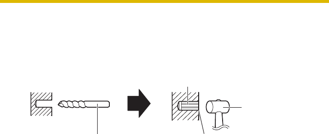
Making holes on mortar or concrete wall
1. Put flexible stand on the wall where you plan to install the camera and mark
the points where you are going to make holes.
2. Make holes with an electric drill. Insert plastic plugs (customer-provided) into
the holes and push them inside the holes with the hammer.
Note
Mortar wall is easy to come off in drilling.
3. Mount the flexible stand by using the screws (accessories).
Change the drill depending on the
concrete wall or the tiled wall. Caulk around the holes
if necessary.
Plastic Plug
Hammer

Installation/Troubleshooting
[For assistance, please call: 1-800-272-7033] 47
2 Troubleshooting
The Panasonic Network Camera support website "http://panasonic.co.jp/pcc/
products/en/netwkcam/" includes various technical information other than the contents
in this troubleshooting section. Access it if problems occur.
2.1 Indicator Error Codes
Problem Cause and Remedy
Indicator lights
or blinks orange. • Ethernet cable is not connected properly.
Connect the Ethernet cable properly.
• PC, Ethernet hub or router is not working.
Confirm that PC, Ethernet hub and router is working.
• The wireless settings are not identical with those of the router.
Set the same SSID, Communication mode and WEP as
those of the router.
Indicator
continues
blinking orange.
• Indicator blinks orange when updating firmware.
If you access the camera on the web browser, Update
Firmware page will be displayed. Update the firmware
following the procedure (see page 117 of the Operating
Instructions on the Setup CD-ROM). If you fail to update the
firmware, see page 64.
Indicator
continues
blinking orange
(2-second
interval).
• The router on your network is turned off.
Turn the router on, and wait for a while until the ADSL line is
connected.
• An error occurs in UPnPTM port forwarding.
Set up the camera again in [Automatic Setup] by the Setup
Program following the Getting Started.
Indicator
continues
blinking green.
• Automatic setup is not complete.
Complete the setup following this Installation/
Troubleshooting.
• The camera did not get its IP address from the DHCP server.
When setting [Automatic Setup] or [DHCP Setup], the
camera may not get its IP address due to network failures.
Ask your ISP or network administrator for more information.

Installation/Troubleshooting
48
Indicator does
not light in green
in
communicating
by using the
wireless LAN.
• The status of radio wave is unfavorable. (To check the Wireless
information on the Wireless Status, see page "" of the Operating
Instructions on the Setup CD-ROM.)
Start the communication after changing the location of the
camera or getting rid of the obstacle around the camera.
Indicator does
not light up. • Indicator display is disabled.
Check if the indicator control is disabled (see page 113 of the
Operating Instructions on the Setup CD-ROM).
• Confirm that the standard AC adaptor PQLV202 (Order No.
PQLV202W) is being used.
Indicator
continues
blinking red.
• The camera may be malfunctioning.
If you cannot access the camera, the camera may be
malfunctioning. Call our customer call center.
Problem Cause and Remedy

Installation/Troubleshooting
[For assistance, please call: 1-800-272-7033] 49
2.2 Camera Setup Difficulties
Note
If you are experiencing any problems, it is recommended that you
temporarily disable all firewall, pop-up killer, and virus detection
software. Once the problem is identified and corrected, you can restart
the Setup Program.
Problem Cause and Remedy
Automatic Setup
fails using Setup
Program.
• More than 20 minutes have passed, after turning the camera
on.
Disconnect the plug of the AC cord from the outlet, and
reconnect it again. Set up the camera again following the
Getting Started.
• Multiple camera IP addresses are overlapping.
If you install multiple cameras, turn the camera on one by
one.
Viewnetcam.com
registration fails
using Setup
Program.
• Your PC is not connected to the Internet through the router.
Configure the router for the Internet connection from your
PC following the router manual. And register with the
Viewnetcam.com service.
• If you do not receive an E-mail from the Viewnetcam.com
service, your registered E-mail address may be incorrect.
Register your correct E-mail address again at the
Viewnetcam.com website at
http://www.viewnetcam.com.

Installation/Troubleshooting
50
Setup Program
does not list any
cameras.
• Your firewall or antivirus software is blocking the connection.
To avoid any possible problems, temporarily disable any
firewall or antivirus software, and set up the camera again.
If you cannot disable your firewall or antivirus software, you
can set up the camera using the MAC address (see page
32).
• The camera is connected over a different network.
Set up the camera from a PC under the same router.
• Confirm that an IP address is assigned to your PC.
If the IP address is not assigned to your PC, assign it to your
PC (see page 139 of the Operating Instructions on the
Setup CD-ROM).
Setup Program
fails to complete
successfully.
• Network problems may occur during setup.
Confirm that your network is working. Disconnect the plug
of the AC cord from the outlet, and reconnect it again. Then
set up the camera again following the Getting Started.
• More than 20 minutes have passed, after turning the camera
on.
Disconnect the plug of the AC cord from the outlet, and
reconnect it again. Set up the camera again following the
Getting Started.
UPnPTM port
forwarding setup
fails.
•UPnP
TM is disabled on the router.
Enable UPnPTM on the router following the router manual.
• The camera is turned on before the router is turned on.
Turn the router on first, and then turn the camera on.
• The default gateway is not set, or the settings are wrong.
Set the default gateway correctly (see page 42 of the
Operating Instructions on the Setup CD-ROM).
• The router does not support UPnPTM.
Enable port forwarding on your router following the router
manual.
Problem Cause and Remedy

Installation/Troubleshooting
[For assistance, please call: 1-800-272-7033] 51
2.3 About Wireless Communication
The camera IP
address and port
number have
been forgotten.
• Clicking [Camera Setup] on the Setup Program displays the
camera list. The camera list shows the MAC address labeled
beside the Ethernet (LAN) port. The camera IP address and
port number are shown next to the MAC address.
The password
has been
forgotten.
• Press the FACTORY DEFAULT RESET button to reset the
camera to default. Set up the camera again.
Error is displayed
on the camera
status by the
Setup Program.
• The Setup Program causes the error message.
Disconnect the plug of the AC cord from the outlet, and
reconnect it again.
Problem Cause and Remedy
Wireless
communication
does not work.
• Signal strength is weak.
Change the location of the camera or get rid of the obstacle
around the camera.
• SSID and Encryption setting of the camera are different from
those of the wireless router or the wireless LAN card of PC.
SSID and Encryption setting must be identical between the
camera and wireless router.
Wireless
communication
is unstable.
• The channel for communication is identical with another wireless
network.
The wireless communication may be improved by changing
the channel of the router.
• Another nearby wireless device may be causing interference or
the distance between the wireless camera and your wireless
network may be too great.
Temporarily disable other wireless devices to identify the
source of the interference.
Try repositioning the camera or moving it closer to your
wireless router.
Problem Cause and Remedy

Installation/Troubleshooting
52
2.4 Camera Image/Page Display
Problem Cause and Remedy
The Top page is
not displayed. • The camera IP address has changed.
Enter the new IP address in the address bar of the web
browser.
• Wrong IP address class is assigned to the camera.
IP addresses of the PC and the camera must be in the same
local IP address class. Set the IP address correctly (see
page 139 of the Operating Instructions on the Setup CD-
ROM).
• Router does not have a loopback feature.
Access the camera with the local network IP address.
• You entered IPv6 address in the Internet Explorer.
Internet Explorer does not support IPv6 address access. Use
DDNS services like Viewnetcam.com service.
• The network is congested.
Pages may not be displayed immediately. Wait for a while.
• The web browser is accessing the proxy server.
Set the web browser to access the Internet directly (see page
143 of the Operating Instructions on the Setup CD-ROM).
• The connection type is wrong (see page 45 of the Operating
Instructions on the Setup CD-ROM).
If the camera is not connected to the network in the [Auto
Negotiation] setting, set up the camera and the router seeing
the following table.
Auto Negotiation
Network Camera
Router or hub
Auto
Negotiation
100Base-TX 10Base-TX
Full
Duplex Half
Duplex Full
Duplex Half
Duplex
100Base-
TX
10Base-T
Full Duplex
Half Duplex
Full Duplex
Half Duplex
—
—
—
—
—
—
—
—
—
—
—
—
—
—
— —

Installation/Troubleshooting
[For assistance, please call: 1-800-272-7033] 53
The Top page is
not displayed. • The default gateway or DNS server addresses may be wrong.
The correct IP addresses are required especially when you are
using the Viewnetcam.com service.
Assign the correct default gateway and DNS server
addresses (see page 42 of the Operating Instructions on the
Setup CD-ROM).
The Top page is
displayed on the
LAN, but not
displayed from
the Internet.
• The default gateway address may be wrong.
Assign the correct default gateway address (see page 42 of
the Operating Instructions on the Setup CD-ROM).
•UPnP
TM is disabled on the router.
Enable UPnPTM on the router following the router manual.
• Port forwarding is not enabled on the router (see page 31).
Enable port forwarding seeing the router manual for details.
• Firewalls such as packet filtering on the router is blocking
camera access.
Set the router to allow access to the camera seeing the
router manual for details.
• You are accessing the camera with an IP address for local
camera access.
Access the camera with the global IP address of the router
and port number of the camera.
• The router does not allow access to the camera under the router
with the global IP address.
If you access the camera on the LAN, access with the
address for local camera access.
Authentication
windows are
consequently
displayed.
• User name and password for the administrator or general users
are changed.
Close the web browser, and access the camera again.
Only half of the
image is
displayed.
• You are using Internet Explorer 4.xx or lower.
Upgrade Internet Explorer to version 6.0 or greater.
Problem Cause and Remedy

Installation/Troubleshooting
54
Camera image
is not displayed. • ActiveX Controls are not installed in Internet Explorer.
ActiveX Controls should be installed to display video (Motion
JPEG) (see page 37).
• The network is congested.
Pages may not be displayed immediately. Wait for a while.
• The web browser is accessing the proxy server.
Set the web browser to access the Internet directly (see page
143 of the Operating Instructions on the Setup CD-ROM).
A gray screen is
displayed. • There are currently more than 30 simultaneous accesses to the
video (Motion JPEG).
Reduce the number of access to below 30, or change the
video to still images.
• Operation time has been specified.
A gray screen is displayed outside the operation time. This is
normal.
Video suddenly
changes to still
images.
• The video (Motion JPEG) display period is set on the General
User page.
When you view video continuously, set [Unlimited] for the
limit continuous motion JPEG (see page 79 of the Operating
Instructions on the Setup CD-ROM).
Image is out of
focus. • The lens cover has dust, dirt, fingerprints or droplets on it.
Clean the lens cover with a dry cloth (see page 138 of the
Operating Instructions on the Setup CD-ROM).
• The object is too close to the camera.
The camera cannot focus at short distances (less than 0.5 m
[about 20 inches]). Locate the object more than 0.5 m (about
20 inches) away from the camera.
Problem Cause and Remedy

Installation/Troubleshooting
[For assistance, please call: 1-800-272-7033] 55
The color on the
image is
strange.
• White balance does not work well.
Adjust the white balance on the Camera page (see page 69
of the Operating Instructions on the Setup CD-ROM).
• The color display setting on your PC is set lower than 16 bits.
Set the color display 16 bits or higher.
Image flickers. • The object is dark.
Make the area around the camera brighter.
• A bright object may cause horizontal flickers on the image.
Changing the object improves the flickers. Or adjusting
brightness to the [+] side on the operation bar eases the
flickers.
An old image is
displayed. • The old image is temporarily stored on the web browser.
Set [Every visit to the page] on the web browser to check for
temporary Internet files (see page 146 of the Operating
Instructions on the Setup CD-ROM).
The image
refreshes very
slowly.
• Multiple users are accessing the camera.
If multiple users are accessing the camera, the image
refreshes slowly.
• You are not using an Ethernet switching hub.
If you view multiple cameras on the Multi-Camera page, the
image refreshes slowly. Use an Ethernet switching hub.
• The image may refresh slowly, depending on image resolution,
image quality, network traffic, PC performance, enabling IPsec,
SD memory recording or what object you view.
• The Max. bandwidth usage is limited.
Increase the max. bandwidth usage on your network (see
page 42 of the Operating Instructions on the Setup CD-
ROM).
• The camera is in color night view mode.
The image refreshes slowly in color night view mode. Make
the area around the camera brighter.
Problem Cause and Remedy

Installation/Troubleshooting
56
2.5 Operation Bar
The image stops
refreshing
during the
wireless
communication
with the camera.
• The image may stop refreshing because the wireless
communication can be disconnected depending on the
environment.
Click [Refresh] at the tool bar on the web browser.
Problem Cause and Remedy
Pan/tilt, click to
center and
preset features
do not work.
• Your PC is not connected to the camera.
Click [Refresh] on the web browser. Confirm that the image
refreshes, and operate the pan/tilt functions.
• The camera is not turned on.
Confirm that the camera is turned on.
• Multiple users are operating the camera simultaneously.
Wait for a while, and access the camera again.
• The pan/tilt reaches its end.
Confirm that the end display is displayed on the operation
bar.
• The pan/tilt range is restricted.
Adjust the pan/tilt range settings (see page 72 of the
Operating Instructions on the Setup CD-ROM).
Part of the
buttons on the
operation bar
are not
displayed.
• The feature is not permitted on the General User page.
Permit the feature to be used (see page 79 of the Operating
Instructions on the Setup CD-ROM). Or log in to the camera
as an administrator.
Problem Cause and Remedy
Installation/Troubleshooting
[For assistance, please call: 1-800-272-7033] 57
2.6 Audio Problems
Problem Cause and Remedy
The audio
buttons are not
displayed.
• The [Output] or [Input] settings are set to [Disable] on the Audio
page.
Change them to [Enable]. (See page 73 of the Operating
Instructions on the Setup CD-ROM)
• In the access level settings on the General User page, [Listen]
and [Talk] are not permitted.
Permit [Listen] and [Talk]. (See page 79 of the Operating
Instructions on the Setup CD-ROM)
Neither Listen or
Talk button can
be used.
• When accessing a camera on a LAN, the web browser settings
are going through a proxy server.
Change the settings so that they do not go through a proxy
server. (see page 143 of Operating Instructions on the Setup
CD-ROM)
Audio cannot be
heard on the
computer.
•The Listen button appears like this:
Click the Listen button. (It will change to .)
• The audio operation toolbar display is gray.
[Listen] is not permitted on the General User page. Permit it.
(see page 79 of Operating Instructions on the Setup CD-
ROM)
• The volume is set to minimum.
Adjust the volume on the volume adjustment toolbar.
• The computer volume is set to mute or minimum volume.
Open the PC's Volume Control window, and clear the output
master and Wave/MP3's Mute checkbox, then adjust the
volume.
• appears in the audio toolbar.
There are too many simultaneous audio connections. Wait
for a while, and try to access again.

Installation/Troubleshooting
58
Audio is not
produced from
an external
speaker
connected to
the camera.
•The Talk button appears like this:
Click the Talk button. (It will change to .)
• The Talk button is gray.
[Talk] is not permitted on the General User page. Permit it
(see page 79 of Operating Instructions on the Setup CD-
ROM).
• Microphone is not selected on your PC's volume control screen.
Click [Options] [Properties] , and check [Recording] on
the Volume Control window. In the "Show the following
volume controls" column, check [Microphone], and click
[OK]. Check [Select] on the Recording Control window.
• The PC's microphone input setting is set to mute.
Open the PC's Volume Control window, check the
microphone checkbox and then adjust the volume controls.
• A speaker is not connected to the camera.
Connect an external speaker to the camera.
• An amplifier is not connected to the camera.
The camera's audio output terminal is a line output. Connect
it to an external speaker with a built-in amplifier (see page 30
of Operating Instructions on the Setup CD-ROM).
• Audio can only be received for short periods of time.
Change the settings to extend the PC Audio Input Timeout
(see page 73 of Operating Instructions on the Setup CD-
ROM).
• The camera speaker volume settings are set to minimum.
Adjust the volume settings to an appropriate volume.
• The camera access is going through a proxy server.
The audio feature cannot be used when going through a
proxy server.
Problem Cause and Remedy

Installation/Troubleshooting
[For assistance, please call: 1-800-272-7033] 59
Noise can be
heard. • The plug of the external microphone or speaker is dirty.
Wipe the connection terminal of the microphone or speaker.
• The external microphone or speaker is not connected properly.
Correctly connect the external microphone or speaker.
• The audio from your PC speaker is being caught by your PC
microphone, then the camera is transmitting the audio as the
noise.
Check [mute] for the microphone column on the volume
control screen. Then the PC will stop transmitting audio to
the camera.
Audio is
interrupted. • Other applications are being run on the computer.
Close other applications on your computer.
• The max. bandwidth is set to [Unlimited] on the Network page.
Reduce the max. bandwidth (see page 45 or page 49 of
Operating Instructions on the Setup CD-ROM).
• The mute for pan/tilt is set to [Enable] on the Audio page.
This is not a problem.
• The input from the external microphone or speaker is small.
When the audio is interrupted in listening, change
sensitiveness to [Maximum] on the Audio page. When the
audio is interrupted in talking, adjust the microphone volume
on the PC's Volume Control window.
Problem Cause and Remedy

Installation/Troubleshooting
60
2.7 Image Buffer/Image Transfer
Problem Cause and Remedy
The camera
does not
transfer the
image by E-mail
or FTP.
• Errors have occurred on the way to the E-mail or FTP server.
See the Protocol column on the Status page (see page 115
of the Operating Instructions on the Setup CD-ROM), and
check if the error is displayed.
• The default gateway and DNS server addresses are not
assigned correctly.
Assign them correctly (see page 42 of the Operating
Instructions on the Setup CD-ROM).
• Login ID and password for E-mail or FTP are invalid.
Make sure that you enter your correct login ID and password.
The camera
does not
transfer the
image to a
mobile phone.
• The image quality is not set to [Mobile Phone] on the Image
Buffer/Transfer page.
Set the resolution to [160 x 120] and the image quality to
[Mobile Phone]. Some mobile phones do not support 320 x
240 resolution.
The image is
slowed down on
the Buffered
Image page. Or
the camera
transfers the old
image.
• The transfer interval is too short.
Set the transfer interval longer than the current setting (see
page 90 or page 100 of the Operating Instructions on the
Setup CD-ROM).

Installation/Troubleshooting
[For assistance, please call: 1-800-272-7033] 61
2.8 SD Memory Recording
2.9 IPv6
Problem Cause and Remedy
Cannot write
onto the SD
memory card.
• It is writing protected.
Cancel the writing protection.
It takes time to
record. • Sometimes it takes time when it is formatted on a PC.
Format it on the camera (see page 86 of Operating
Instructions on the Setup CD-ROM).
Problem Cause and Remedy
The Top page is
not displayed
with the IPv6
address.
• The IPv6 address is not set on the camera.
Check if the IP address and default gateway are displayed in
the network (IPv6) column of the status page (see page 115
of Operating Instructions on the Setup CD-ROM). If neither
or only one is displayed, it is possible that the connection is
incorrect or that the IPv6 router is not set properly. Set them
correctly.
• The IPv6 has not been set up on your PC.
IPv6 is not set up in Windows XP when purchased. Change
the settings to enable it. (see page 16 of Operating
Instructions on the Setup CD-ROM)
• Router filtering is enabled.
Permit camera access from the WAN side in router settings.
• Your network or ISP may not support IPv6 at this time.

Installation/Troubleshooting
62
2.10 IPsec
Problem Cause and Remedy
The camera
cannot be
accessed in
transport mode.
• IPsec policy settings are restricted.
Decrease the number of computers connected
simultaneously, and wait for a while, or shorten the lifetime in
the PC's IPsec settings.
• IPsec settings have not been set on your PC.
Set IPsec settings on your PC. See the Panasonic Network
Camera support website (http://panasonic.co.jp/pcc/
products/en/netwkcam/) for how to do this.
• The pre-shared key is not set correctly.
Set the same pre-shared key for the camera and your PC
(see page 53 of Operating Instructions on the Setup CD-
ROM).
• On the VPN router within the network, tunnel mode has been
set.
Transport mode and tunnel mode can not be used at the
same time. Cancel the PC's IPsec settings, and
communicate using tunnel mode.
• Either PC's SA or Camera's SA is not established.
Disable the PC's IPsec settings, and enable it again.
The camera
cannot be
accessed on
tunnel mode.
• The pre-shared key is not set correctly.
Set the same pre-shared key for the camera and the VPN
router (see page 56 of Operating Instructions on the Setup
CD-ROM).
• The VPN router is not set correctly.
Set the IKE and IPsec policy on the VPN router correctly (see
page 56 of Operating Instructions on the Setup CD-ROM).
• Either VPN router's SA or camera's SA is not established.
Restart the VPN router and the camera.

Installation/Troubleshooting
[For assistance, please call: 1-800-272-7033] 63
E-mail or FTP
transfer cannot
be sent in
transport mode.
• The network settings are not set correctly.
Cancel the IPsec settings on the server, PC and camera, and
check that the camera images can be transferred. If they can
be transferred, the IPsec settings were not set correctly. Set
them correctly (see page 53 of Operating Instructions on the
Setup CD-ROM).
• The pre-shared key is not set correctly.
Set the same pre-shared key for the camera, and server (see
page 53 of Operating Instructions on the Setup CD-ROM).
• There is a e-mail server or FTP server within the tunnel mode
network.
Transport mode and tunnel mode cannot be used at the
same time. Cancel the e-mail server or FTP server's IPsec
settings, and communicate using tunnel mode.
• Either server's SA or camera's SA is not established.
Restart the camera.
Problem Cause and Remedy
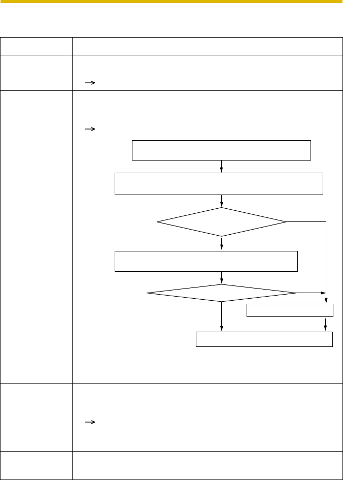
Installation/Troubleshooting
64
2.11 Miscellaneous
Problem Cause and Remedy
ActiveX cannot
be installed. • Security software disables the ActiveX installation.
Close the security software, and install the ActiveX again.
The firmware is
not updated. • The firmware updating is not completed due to power off,
network failure or other causes.
Update the firmware again following the next procedures.
*1See page 117 of the Operating Instructions on the Setup CD-
ROM about updating firmware.
Shortcut icon is
not displayed in
the My Network
Places folder.
•UPnP
TM Windows component is not installed in Windows XP or
Windows Me.
Install UPnPTM Windows component in Windows XP or
Windows Me (see page 146 of the Operating Instructions on
the Setup CD-ROM).
You cannot
solve problems. • Call our customer call center at 1-800-272-7033.
No
Yes
No
Yes
Disconnect the plug of the AC cord of the
camera from the outlet, and reconnect it again.
Enter the IP address on the web browser to access
the camera.
Is the Top page displayed?
Is the version updated?
Access the Setup page and click [Status].
Check the firmware version on the Status page.
Update the firmware*1.
The firmware update is completed.

Installation/Troubleshooting
[For assistance, please call: 1-800-272-7033] 65
Memo
KK1104JT0
PSQX3498ZA
Panasonic Consumer Electronics Company,
Division of Matsushita Electric Corporation of America
Printed in Japan
2004
Panasonic Communications
Co., Ltd. All Rights Reserved.
Panasonic Sales Company,
Division of Matsushita Electric of Puerto Rico, Inc.
Carefully pack your unit, preferably in the original carton.
Attach a letter, detailing the symptom, to the outside of the carton.
Symptom
Operating Instructions are subject to change without notice.
Send the unit to an authorized servicenter, prepaid and adequately insured.
Do not send your unit to the Panasonic Consumer Electronics Company listed below or to
executive or regional sales offices. These locations do not repair consumer products.
When you ship the product
Panasonic Servicenters are listed in the servicenter directory.
Call 1-800-272-7033 for the location of an authorized servicenter.
This Network Camera is designed for use in the United States of America.
Sale or use of this product in other countries/areas may violate local laws.
For product service
Copyright:
This material is copyrighted by Panasonic Communications Co., Ltd., and may be reproduced
for internal use only. All other reproduction, in whole or in part, is prohibited without the written
consent of Panasonic Communications Co., Ltd.