Panasonic of North America 96NBL-C230 2.4 GHz Wireless Network Camera User Manual 2
Panasonic Corporation of North America 2.4 GHz Wireless Network Camera 2
Contents
- 1. Users Manual 1
- 2. User Manual 2
User Manual 2

Operating Instructions
Network Camera
Indoor Use Only
Model No. BL-C210
(Wired Type)
BL-C230
(Wireless/Wired Type)
BL-C230A
BL-C230CE
BL-C230E
BL-C210A BL-C210CE
BL-C210E
Please read this document before using the product, and save this document for future reference.
Panasonic Network Camera Website: http://panasonic.net/pcc/ipcam/

Main Features
On-site and remote camera monitoring
Camera images can be monitored from a PC, both on-site and over the Internet. You can even use your mobile
phone to view still images when you’re out of the house.
H.264, MPEG-4, and Motion JPEG (MJPEG) support
Live camera images can be viewed and buffered (i.e., stored in memory) in H.264, MPEG-4, and JPEG
(MJPEG) formats, allowing you to select the video format that best suits your needs.
Built-in sensor (human detection sensor)
The camera features a built-in pyroelectric infrared sensor, which uses infrared rays to detect temperature
differences within its range that are emitted naturally by people, animals, etc. The sensor can be used to trigger
the camera to buffer (i.e., temporarily store) camera images in its memory. You can view these images later
as desired. The sensor can also be used to trigger the camera to transfer images to someone or somewhere,
by FTP, E-mail, or HTTP.
Backlight Correction feature
When this feature is enabled, the camera can automatically correct the contrast in dark areas of the camera
image. This means even when there is backlight or a large amount of contrast in the image, the camera can
correct the image to provide a more consistent, natural image.
Audio features
The camera features a built-in microphone that allows you to monitor the audio while viewing live camera
images using your PC.
Detection features
The camera’s motion or sound detection feature allows you to buffer or transfer camera images when the
camera detects motion or sound in the camera image.
Camera image buffering and playback
Camera images can be automatically buffered at specific times, when the camera’s external sensors
(customer-provided) are triggered, or when the camera detects motion. You can program the camera to buffer
these camera images, and then you can play back these images later while accessing the camera or save
them to your PC. You can also program the camera to transfer images by E-mail or upload them to an FTP or
HTTP server as they are being buffered.
Digital zoom
When viewing camera images from a PC, you can zoom up to 3´ (by length) and get a closer look. You can
use your mouse to zoom in and out simply.
2 Operating Instructions
Main Features

Protecting your privacy
Simply press the camera’s PRIVACY button to hide the lens from view and protect your privacy. You can even
activate the privacy mode while away from home.
UPnP™ support
When connecting the camera to a UPnP™ compatible router, the camera’s network settings can be
automatically configured, making setup quick and easy. For more information, see Page 100.
Viewnetcam.com support
After registering your camera with the Viewnetcam.com service, you can access the camera while away from
home using an easy to remember Internet address of your choosing, such as ***.viewnetcam.com. For
more information, see Page 105.
Multi-language support
All camera pages can be displayed in English, French, German, Italian, Spanish, Russian, Simplified Chinese,
and Japanese. The most commonly used camera pages can be displayed in Korean.
Wireless connectivity (BL-C230 only)
The BL-C230 supports wireless standards IEEE 802.11b and IEEE 802.11g, giving you the option of using the
camera in either wired or wireless mode. When used in wireless mode, WEP, WPA-PSK(TKIP), and
WPA2-PSK(AES) support ensures that access to the camera is secure.
Operating Instructions 3
Main Features

Other Information
About this document
•This document is written for both the BL-C210 (Wired Type) and the BL-C230 (Wireless/Wired Type).
Available features and operations vary slightly depending on the model. You can confirm the model no. of
your camera by checking the model no. printed on the front of the camera. Features and operations that
apply to a specific camera are indicated by model no. (for example, “BL-C230 only”) in this document.
•The camera illustrations in this document depict the BL-C230A.
•Model number suffixes (“A”, “CE”, and “E”) are omitted from the following model numbers shown in this
document, unless necessary.
BL-C210A, BL-C210CE, BL-C210E, BL-C230A, BL-C230CE, BL-C230E
Trademarks
•Microsoft, Windows, Windows Vista, Hotmail, ActiveX, Internet Explorer, Windows Media, DirectShow, and
DirectDraw are either registered trademarks or trademarks of Microsoft Corporation in the United States
and/or other countries.
•Screen shots reprinted with permission from Microsoft Corporation.
•All other trademarks identified herein are the property of their respective owners.
Abbreviations
•UPnP is the abbreviation for “Universal Plug and Play”.
•The Network Camera is referred to as “the camera” in this document.
•The Setup CD-ROM is referred to as “the CD-ROM” in this document.
Software information
•This software is based in part on the work of the Independent JPEG Group.
•This software includes certain software derived from the RSA Security, Inc. MD5 Message-Digest
Algorithm.
4 Operating Instructions
Other Information

Table of Contents
1 Camera Monitoring ..................................................................................8
1.1 Accessing the Camera ......................................................................................................8
1.2 Viewing Live Camera Images .........................................................................................10
1.2.1 Using the Operation Bar .................................................................................................24
1.2.2 Aiming the Camera Lens ................................................................................................26
1.2.3 Limiting the Pan/Tilt Range ............................................................................................28
1.2.4 Registering and Changing Presets .................................................................................29
1.2.5 Zooming .........................................................................................................................30
1.2.6 Backlight Correction .......................................................................................................31
1.2.7 White Balance ................................................................................................................32
1.2.8 Video Images and Image Refresh Rate .........................................................................33
1.2.9 Taking Snapshots ...........................................................................................................35
1.2.10 Audio Features ...............................................................................................................36
1.2.11 Additional Features Available While Viewing Live Camera Images ...............................37
1.3 Viewing Multiple Camera Images ..................................................................................45
1.4 Maximum Number of Viewing Sessions .......................................................................48
1.5 Maximum Number of Viewing Sessions in Wireless Mode (BL-C230 Only) ..............49
2 Using Triggers to Buffer and Transfer Images ....................................50
2.1 Configuring a Timer Trigger ...........................................................................................51
2.2 Configuring a Sensor, Alarm, or Detection Trigger .....................................................54
2.3 Disabling and Enabling a Trigger ..................................................................................59
2.4 Configuring the Camera to Transfer Images ................................................................60
2.4.1 Transferring Images by FTP ...........................................................................................61
2.4.2 Transferring Images by E-mail .......................................................................................63
2.4.3 Transferring Images by HTTP ........................................................................................66
2.5 Configuring the Camera to Send Trigger Notifications ...............................................68
2.5.1 Sending Trigger Notifications by E-mail .........................................................................69
2.5.2 Sending Trigger Notifications by HTTP ..........................................................................72
2.6 Viewing Buffered Images ...............................................................................................73
2.7 Deleting Buffered Images Manually ..............................................................................77
2.8 Understanding How the Camera Manages Buffered Images ......................................79
2.9 Adjusting Sensor Sensitivity .........................................................................................81
2.10 Adjusting Motion Detection Sensitivity ........................................................................82
2.11 Adjusting Sound Detection Sensitivity .........................................................................84
2.12 Sending Alarm Log Information ....................................................................................87
3 Mobile Phone Features ..........................................................................90
3.1 Accessing the Camera from Your Mobile Phone .........................................................91
3.2 Viewing Still Images on Your Mobile Phone .................................................................92
3.3 Viewing Alarm Logs on Your Mobile Phone .................................................................94
3.4 Enabling and Disabling Image Buffering Using Your Mobile Phone .........................95
4 Configuring the Camera for Access from the Internet .......................96
4.1 Configuring Port Forwarding .......................................................................................100
4.2 Configuring the Camera to Use a Dynamic DNS Service ..........................................104
4.2.1 Configuring the Camera to Use Viewnetcam.com .......................................................105
4.2.2 Configuring the Camera to Use a Third-party Dynamic DNS Service ..........................109
4.3 Confirming Internet Access .........................................................................................111
5 Changing Camera Settings .................................................................112
5.1 Network Settings ...........................................................................................................112
Operating Instructions 5
Table of Contents

5.1.1 Network (IPv4) Settings ................................................................................................113
5.1.2 Proxy Server Settings ...................................................................................................118
5.2 HTTPS Settings .............................................................................................................119
5.3 Using the Camera in Wireless Mode (BL-C230 Only) ................................................133
5.3.1 Configuring the Camera for Wireless Connection (BL-C230 Only) ..............................134
5.3.2 Restarting the Camera in Wireless Mode (BL-C230 Only) ...........................................138
5.4 UPnP™ Settings ............................................................................................................139
5.5 Setting the Date and Time ............................................................................................140
5.6 Changing Basic Camera Settings ................................................................................142
5.7 Changing Audio Settings .............................................................................................144
5.8 Changing Video Streaming Settings ...........................................................................145
6 User Accounts ......................................................................................150
6.1 Understanding User Accounts ....................................................................................150
6.2 Changing the Administrator User Name and Password ...........................................151
6.3 General Users ................................................................................................................152
6.4 Guest Users ...................................................................................................................155
6.5 The Login Tab ................................................................................................................158
7 Advanced Settings ...............................................................................159
7.1 Changing Image Display Settings ...............................................................................159
7.2 Registering Multiple Cameras ......................................................................................163
7.3 Specifying Operation Times .........................................................................................166
7.4 Controlling the External Output Terminal (BL-C230 Only) ........................................168
7.5 Changing the Indicator Display ...................................................................................169
7.6 Privacy Mode .................................................................................................................170
7.7 Managing Registered Devices (BL-C210A/BL-C230A Only) .....................................172
7.8 Built-in Alarm Settings .................................................................................................174
8 Camera Administration and Maintenance .........................................176
8.1 Confirming Camera Status ...........................................................................................176
8.2 Confirming Wireless Status (BL-C230 Only) ..............................................................177
8.3 Confirming Session Status ..........................................................................................178
8.4 Confirming Alarm Logs ................................................................................................179
8.5 Restarting the Camera ..................................................................................................180
8.6 Updating the Camera’s Firmware ................................................................................181
8.7 Saving Settings in a Configuration File ......................................................................182
8.8 Restoring Settings from a Configuration File ............................................................183
8.9 Resetting the Camera ...................................................................................................184
9 The [Support] Tab ................................................................................186
10 Using IPv6 .............................................................................................187
10.1 Configuring Your Router for IPv6 ................................................................................188
10.2 Configuring Your PC for IPv6 ......................................................................................189
10.3 Configuring Your Camera for IPv6 ..............................................................................190
10.4 Accessing the Camera in IPv6 Mode ...........................................................................193
10.5 Allowing IPv6 Access from the Internet ......................................................................194
11 PC Settings ...........................................................................................195
11.1 Proxy Server Settings ...................................................................................................195
11.2 Creating a Shortcut to the Camera ..............................................................................198
11.3 Changing the Browser’s Temporary Internet Files Setting .......................................199
11.4 About the MPEG-4 Viewer Program ............................................................................200
11.5 About the H.264 Viewer Program ................................................................................201
6 Operating Instructions
Table of Contents

12 Using the Setup Program ....................................................................202
13 Technical Information ..........................................................................205
13.1 Cleaning the Camera ....................................................................................................205
13.2 ASCII Character Table ..................................................................................................206
13.3 Internal Memory Capacity for Buffered Images .........................................................207
13.4 Information About Streaming Format .........................................................................208
13.5 Feature Limitations Based on Image Format .............................................................209
13.6 Comparing Color Night View and Software Color Night View ..................................210
13.7 Default Setting List .......................................................................................................211
13.8 Specifications ................................................................................................................229
Operating Instructions 7
Table of Contents

1 Camera Monitoring
1.1 Accessing the Camera
You will need to know the following information to access the camera.
•The camera’s IP address (e.g., 192.168.0.253) or URL (e.g., ***.viewnetcam.com)
•The port number of the camera, if it is not 80.
•The user name and password required to access the camera, which were set during camera setup.
1. Start your PC’s web browser.
2. In the browser’s address bar, enter http:// followed by the IP address of the camera, then press
[Enter] on the keyboard.
Example: http://192.168.0.253
•If the camera’s port number is a port number other than 80, enter “:” and the port number after the IP
address.
Example: http://192.168.0.253:50001
•If you have registered with a Dynamic DNS service, such as Viewnetcam.com (see Page 105), enter
the URL instead of the IP address. Note that accessing the camera this way may only work when you
are accessing the camera from outside, i.e., from a PC that is not connected to the same network as
the camera.
Example: http://***.viewnetcam.com
If the camera’s port number is a port number other than 80, enter “:” and the port number after the
URL.
Example: http://***.viewnetcam.com:50001
•If the camera is configured to use HTTPS (see Page 119), enter https:// followed by the IP address
or host name and the port number of the camera.
Example: https://192.168.0.253:80
Example: https://***.viewnetcam.com:80
3. When the authentication dialog is displayed, enter the user name and password, then click [OK]. The top
page is displayed.
Note
•If the authentication dialog is not displayed, click the [Login] tab after the camera’s top page is
displayed. For more information, see Page 158.
•If a security warning is displayed when accessing the camera using HTTPS, see Page 119.
•BL-C210A/BL-C230A only: If the camera is accessed while the camera is in registration mode,
[Registering...] is displayed.
8 Operating Instructions
1.1 Accessing the Camera
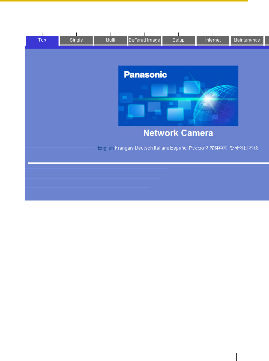
4. After the top page is displayed, click the desired tab. (Depending on how the camera has been configured,
certain tabs may not be displayed.)
XXXX
Version XXX
Running in IPv4 mode.
A B C D
K
L
M
J
G H IE F
A. To display the top page
B. To view images from this camera (see Page 10)
C. To view images from multiple cameras (see Page 45)
D. To view buffered camera images (see Page 73)
E. To configure the camera
F. To configure the camera to be accessed over the Internet (see Page 96)
G. To confirm camera status and perform camera maintenance (see Page 176)
H. To view URLs for Panasonic Network Camera support sites on the Internet (see Page 186)
I. To log in to the camera as the administrator or as a general user (see Page 158)
J. Click the desired display language
K. Displays the camera’s model number
L. Displays the camera’s firmware version number
M. Displays [IPv4] or [IPv6] depending on the camera’s network configuration
Operating Instructions 9
1.1 Accessing the Camera

1.2 Viewing Live Camera Images
1. Access the camera (see Page 8).
2. Click the [Single] tab.
•Viewer programs (ActiveX® Controls) must be installed in order to view H.264, MPEG-4, and MJPEG
images, and to use audio features. If the appropriate viewer program (ActiveX Control) is not installed,
the camera will prompt you to install them. For more information, see Page 16, Page 17, or
Page 19 depending on which Internet Explorer® you are using.
•If the camera image is not displayed, or if the ActiveX message is displayed at the top of the screen,
see Page 23.
10 Operating Instructions
1.2 Viewing Live Camera Images
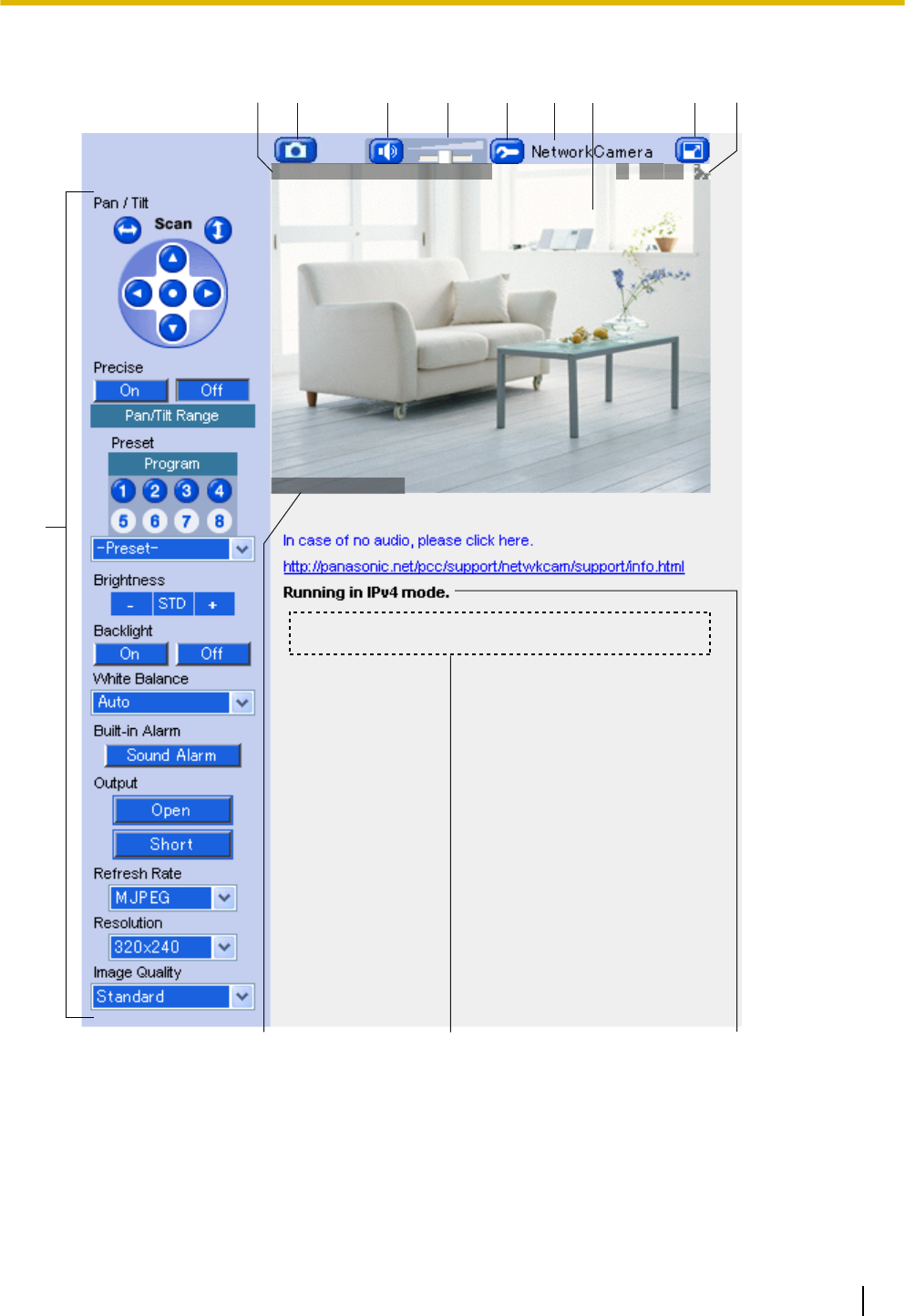
The single camera page (MJPEG/JPEG)
JUN.18,09 11:29:59AM
Text Overlay
O MS12
BA D E
J
CGHI
L
K
M
F
A. Date and time overlay (see Page 159)
B. Snapshot button (see Page 35)
C. Listen button (see Page 36)
D. Volume slider (see Page 36)
E. Additional Features button (see Page 37)
F. Camera name (see Page 159)
Operating Instructions 11
1.2 Viewing Live Camera Images

G. Camera image (click an area of the camera image to use the click to center feature (see Page 26), or
use your mouse to use the zoom feature (see Page 30) when displaying images)
H. Full-screen button (click to view the image in 4:3 full-screen mode; click to return to normal mode)
I. Status overlay (see Page 159)
J. Operation bar (see Page 24)
K. Text overlay (see Page 159)
L. Banner (see Page 159)
M. Displays [IPv4] or [IPv6] depending on the camera’s network configuration
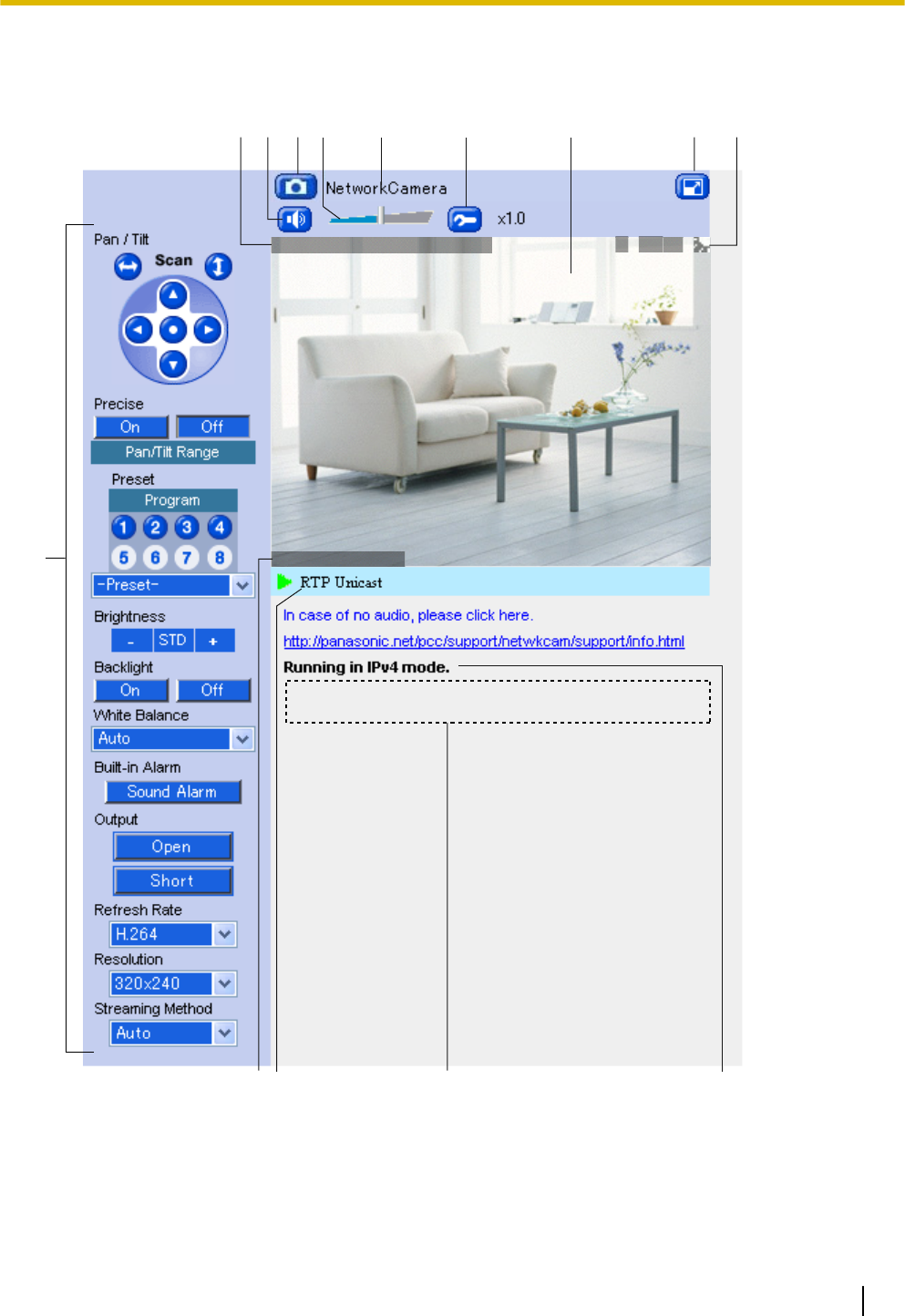
The single camera page (H.264/MPEG-4)
H.264 or MPEG-4 images can be viewed by selecting [H.264] or [MPEG-4], respectively, under the refresh
rate selector on the single camera page.
Note
•The first time you select H.264 or MPEG-4 as the refresh rate, a license agreement is displayed. If you
agree to the terms of the license, select [I accept the License agreement], then click [OK]. You will then
be prompted to install the viewer program (ActiveX Controls).
12 Operating Instructions
1.2 Viewing Live Camera Images
•Whether H.264 or MPEG-4 is available (BL-C210A/BL-C230A: H.264 is available by default,
BL-C210CE/BL-C210E/BL-C230CE/BL-C230E: MPEG-4 is available by default) depends on the
[Streaming Format] on the [Video Streaming] page (see Page 145).
JUN.18,09 11:29:59AM
Text Overlay
O MS12
CDBA E F G
J
IH
M
KL
N
A. Date and time overlay (see Page 159)
B. Listen button (see Page 36)
C. Snapshot button (see Page 35)
D. Volume slider (see Page 36)
E. Camera name (see Page 159)
Operating Instructions 13
1.2 Viewing Live Camera Images

F. Additional Features button (see Page 37)
G. Camera image (click an area of the camera image to use the click to center feature (see Page 26), or
use your mouse to use the zoom feature (see Page 30) when displaying images)
H. Full-screen button (click to view the image in 4:3 full-screen mode; click to return to normal mode)
I. Status overlay (see Page 159)
J. Operation bar (see Page 24)
K. Text overlay (see Page 159)
L. H.264 or MPEG-4 streaming method (see Page 33)
M. Banner (see Page 159)
N. Displays [IPv4] or [IPv6] depending on the camera’s network configuration
Note
Image display
•Screen content varies by model number.
•If no camera image is displayed, the appropriate viewer program (ActiveX Controls) may not be
installed. See Page 16, Page 17, or Page 19 for more information.
•If the camera image is not displayed immediately or correctly, click your web browser’s refresh button
to display the latest camera image.
•The image refresh rate may vary depending on network conditions, PC performance, the number of
people accessing the camera, and the type of objects being viewed.
•When the camera is in a dark environment, color night view mode (if enabled; see Page 142)
automatically brightens the image, however the image refresh rate may decrease (i.e., images may
appear choppy) and overall image quality may decrease (i.e., images may appear grainy).
•When the camera is in a dark environment, white or colored dots or horizontal lines may be displayed
in the camera image. This is a characteristic of the camera’s image sensor, and is not a malfunction.
•A gray screen (MJPEG, MPEG-4) or black screen (H.264) is displayed instead of the camera image
in the following situations:
–The camera’s privacy mode (see Page 170) has been turned on. If viewing H.264 or MPEG-4
images, the last image displayed before privacy mode was turned on is displayed for about 20
seconds before the screen turns gray or black.
–Too many users are accessing the camera. When the maximum number of accesses has been
exceeded (refer to the tables in Page 48), additional users will see a gray or black screen, and
[The maximum number of accesses has been exceeded.] will be displayed under the camera
image. Click your web browser’s refresh button periodically until you are allowed to view video
images, or use the [Refresh Rate] selector to select to view still images.
–The camera is configured to not display images at this time of day (see Page 166). [The operation
time has ended.] will be displayed under the camera image. If viewing H.264 or MPEG-4 images,
the last image displayed before the operation time ended is displayed for about 20 seconds before
the screen turns gray or black.
•If old images are displayed when you access the camera, change the browser’s temporary Internet
files setting (see Page 199).
Related settings
•The default settings for [Refresh Rate], [Resolution], and [Image Quality] that are used each time the
single camera page is accessed can be changed (see Page 159).
•Using the [Refresh Rate] selector in the operation bar, you can select whether video images (H.264,
MPEG-4, MJPEG) are displayed, or still images that are refreshed periodically (3 seconds, 5 seconds,
etc.) are displayed.
•To reduce data traffic when other users are accessing the camera, you can configure the camera to
automatically switch from displaying video images to still images. Set the [Video Display Time] for
general users (see Page 152) and for guest users (see Page 155).
BL-C230 only
14 Operating Instructions
1.2 Viewing Live Camera Images

•If using the camera in wireless mode, camera images will stop refreshing if there is a disturbance in
the wireless signal. If you experience difficulty when accessing the camera in wireless mode, refer to
1.4 Wireless Connection Issues (BL-C230 Only) in the Troubleshooting Guide.
Operating Instructions 15
1.2 Viewing Live Camera Images
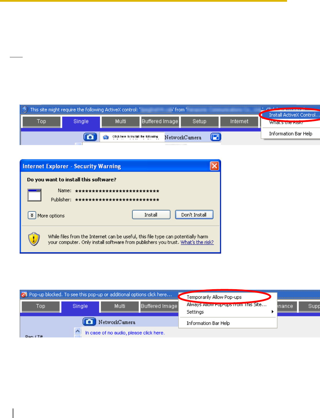
ActiveX dialog for Internet Explorer 6
To view video images (i.e., H.264, MPEG-4, and MJPEG images) or use the camera’s audio features, the
corresponding viewer program (ActiveX Controls) must be installed on your PC. Follow the steps below to
install ActiveX Control when using Internet Explorer 6.
Note
•If ActiveX Controls cannot be installed, download them from the Panasonic Network Camera website
(http://panasonic.net/pcc/support/netwkcam/).
Installing for MJPEG
1. When the ActiveX Control message is displayed in Internet Explorer, click the message and select [Install
ActiveX Control...].
2. Click [Install].
Installing for H.264 or MPEG-4
1. When the pop-up block message is displayed in Internet Explorer, click the message and select
[Temporarily Allow Pop-ups].
2. When a license agreement is displayed and you agree to the terms of the license, select [I accept the
License agreement], then click [OK].
16 Operating Instructions
1.2 Viewing Live Camera Images
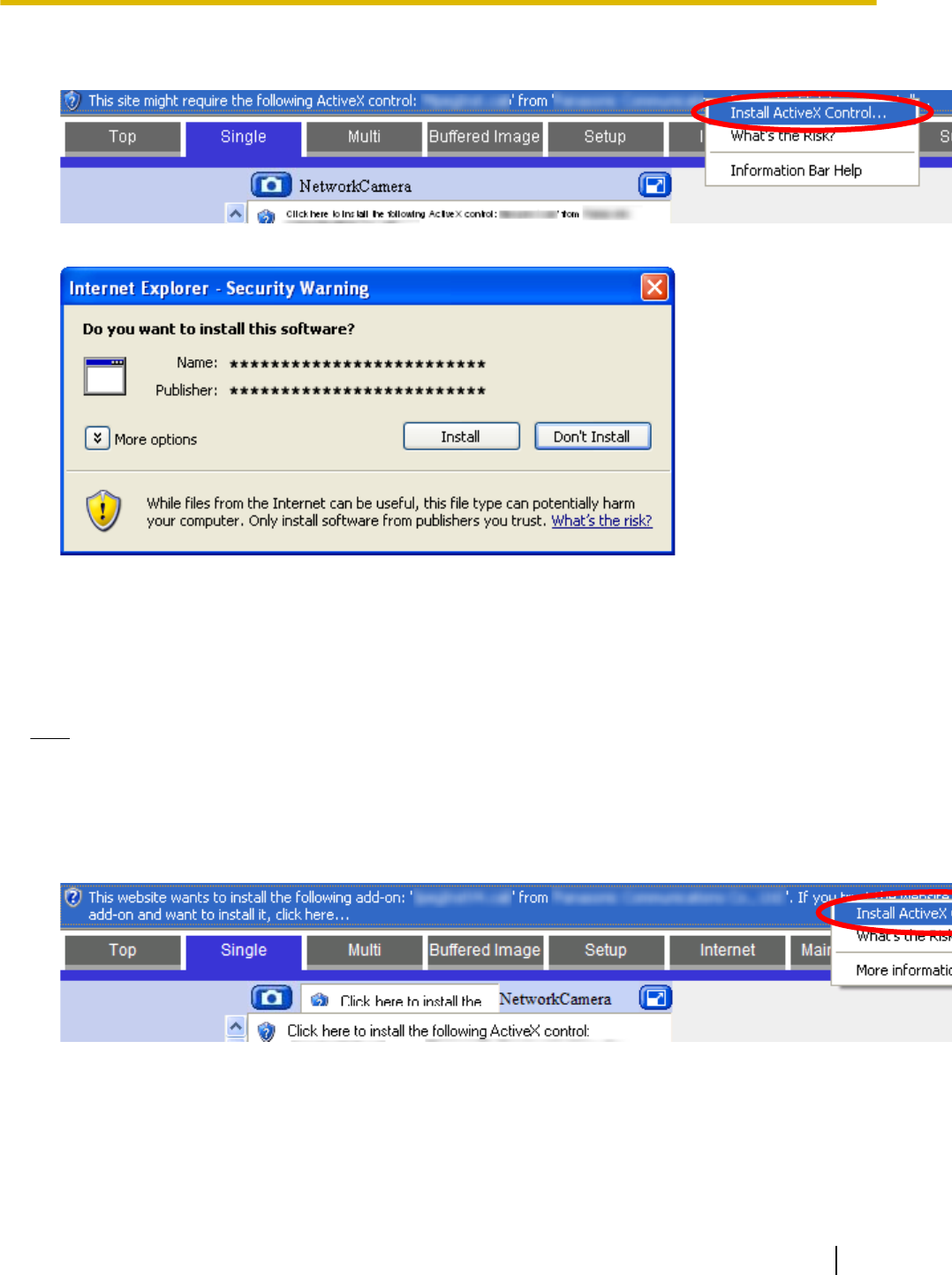
3. When the ActiveX Control message is displayed in Internet Explorer, click the message and select [Install
ActiveX Control...].
4. Click [Install].
ActiveX dialog for Internet Explorer 7
To view video images (i.e., H.264, MPEG-4, and MJPEG images), the corresponding viewer program (ActiveX
Controls) must be installed on your PC. Follow the steps below to install ActiveX Control when using Internet
Explorer 7.
Note
•If ActiveX Controls cannot be installed, download them from the Panasonic Network Camera website
(http://panasonic.net/pcc/support/netwkcam/).
Installing for MJPEG
1. When the ActiveX Control message is displayed in Internet Explorer, click the message and select [Install
ActiveX Control...].
Operating Instructions 17
1.2 Viewing Live Camera Images
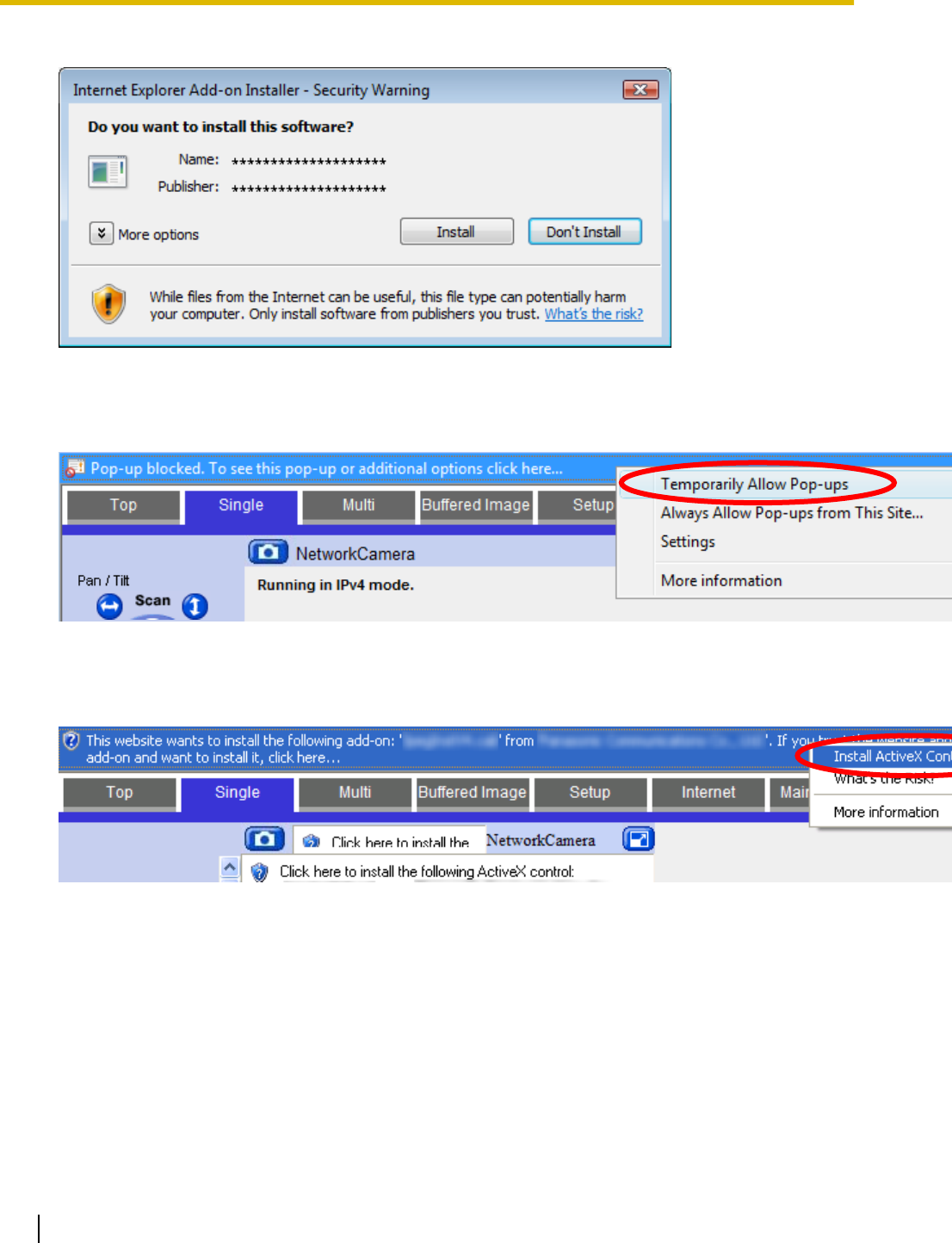
2. Click [Install].
Installing for H.264 or MPEG-4
1. When the pop-up block message is displayed in Internet Explorer, click the message and select
[Temporarily Allow Pop-ups].
2. When a license agreement is displayed and you agree to the terms of the license, select [I accept the
License agreement], then click [OK].
3. When the ActiveX Control message is displayed in Internet Explorer, click the message and select [Install
ActiveX Control...].
18 Operating Instructions
1.2 Viewing Live Camera Images
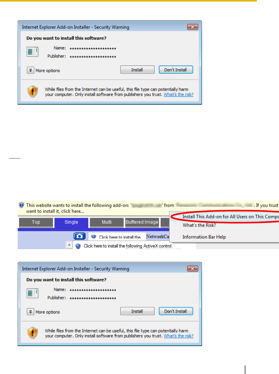
4. Click [Install].
ActiveX dialog for Internet Explorer 8
To view video images (i.e., H.264, MPEG-4, and MJPEG images), the corresponding viewer program (ActiveX
Controls) must be installed on your PC. Follow the steps below to install ActiveX Control when using Internet
Explorer 8.
Note
•If ActiveX Controls cannot be installed, download them from the Panasonic Network Camera website
(http://panasonic.net/pcc/support/netwkcam/).
Installing for MJPEG
1. When the ActiveX Control message is displayed in Internet Explorer, click the message and select [Install
This Add-on for All Users on This Computer...].
2. Click [Install].
Operating Instructions 19
1.2 Viewing Live Camera Images
•If this is the first time you are installing ActiveX Control on this computer, installation is now complete.
Note
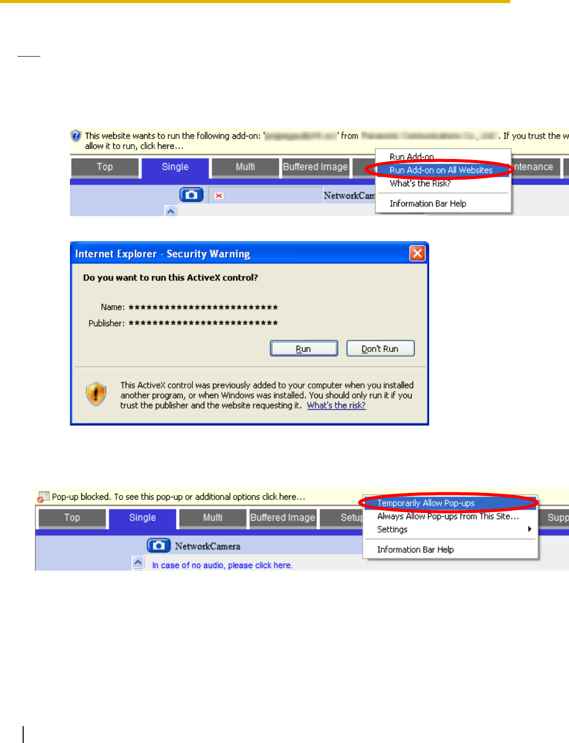
•After the viewer program is installed, the ActiveX Control message is displayed if the audio and video
components (pmjpegaudioV4.ocx and pmjpegcamV4.ocx, respectively) need to be run. Follow the
procedure below and run the components.
1. When the ActiveX Control message is displayed in Internet Explorer, click the message and select
[Run Add-on on All Websites].
2. Click [Run].
Installing for H.264 or MPEG-4
1. When the pop-up block message is displayed in Internet Explorer, click the message and select
[Temporarily Allow Pop-ups].
2. When a license agreement is displayed and you agree to the terms of the license, select [I accept the
License agreement], then click [OK].
20 Operating Instructions
1.2 Viewing Live Camera Images
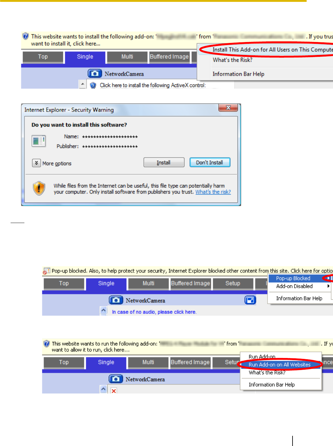
3. When the ActiveX Control message is displayed in Internet Explorer, click the message and select [Install
This Add-on for All Users on This Computer...].
4. Click [Install].
Note
•After the viewer program is installed, the ActiveX Control message is displayed if the MPEG-4 player
component (MPEG-4 Player Module for V4) needs to be run. Follow the procedure below and run the
component.
1. When the pop-up block message is displayed in Internet Explorer, click the message and select
[Pop-up Blocked] ® [Temporarily Allow Pop-ups].
2. When the ActiveX Control message is displayed in Internet Explorer, click the message and select
[Run Add-on on All Websites].
Operating Instructions 21
1.2 Viewing Live Camera Images
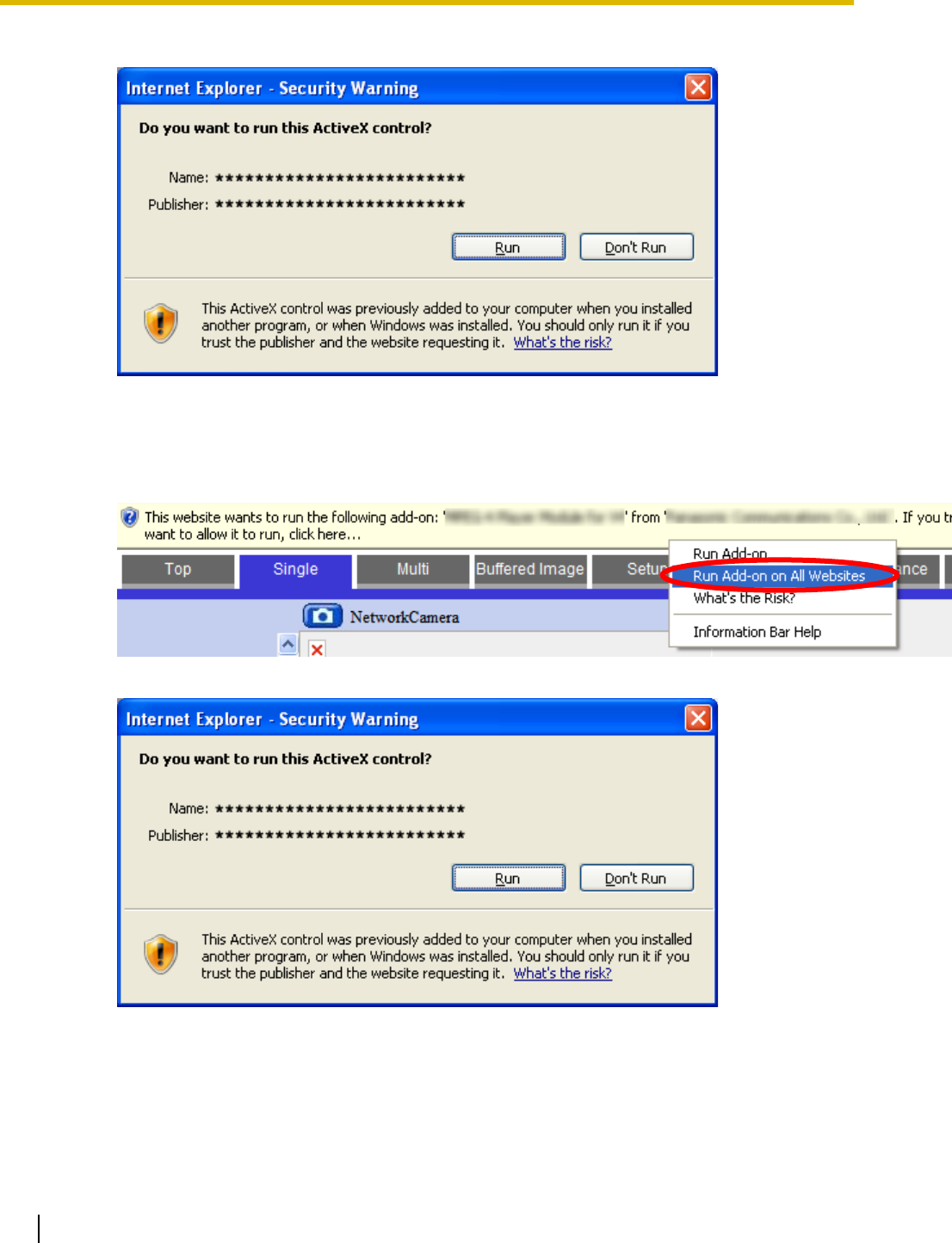
3. Click [Run].
•After the viewer program is installed, the ActiveX Control message is displayed if the H.264 player
component (Pcc Cam ActiveX Control Module) needs to be run. Follow the procedure below and run
the component.
1. When the ActiveX Control message is displayed in Internet Explorer, click the message and select
[Run Add-on on All Websites].
2. Click [Run].
22 Operating Instructions
1.2 Viewing Live Camera Images
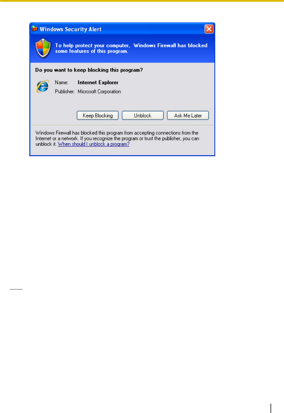
•When the Windows security alert is displayed, click [Unblock].
If you cannot install ActiveX Controls, or if you cannot see video (H.264,
MPEG-4, or MJPEG) images in Internet Explorer
Confirm the following Internet Explorer settings.
1. Click [Tools]®[Internet Options...]®[Security] tab and click [Custom level...] on the web browser.
2. Under [Download signed ActiveX controls], select [Prompt].
3. Under [Run ActiveX controls and plug-ins], select [Enable].
If you need to install ActiveX Controls, you can download them from the Panasonic Network Camera support
site (http://panasonic.net/pcc/support/netwkcam/) or install them using the CD-ROM included with your
camera.
1. Download the ActiveX Controls installer or insert the CD-ROM in your PC.
2. Confirm that Internet Explorer is closed.
3. Double-click the downloaded ActiveX Controls installer, or open the [ocx] folder on the CD-ROM, then open
the [H.264], [MPEG-4], or [MJPEG] folder on the CD-ROM and double-click [install.bat].
Note
•When using Windows Vista®, you must be logged into your PC as a user with Administrator privileges.
For more information, open the [ocx] folder on the CD-ROM, then open the [H.264], [MPEG-4], or
[MJPEG] folder on the CD-ROM and double-click [ReadmeEng.txt].
•After installing or enabling ActiveX Controls, you may need to wait a moment before camera images
are displayed.
•If you use a proxy server, see Page 195.
•If your computer or your network uses a firewall for security purposes, the firewall may prevent video
images from being displayed. In this case, you can use the [Refresh Rate] selector to select to view
still images. If you want to view video images, consult your network administrator.
•If your browser’s pop-up blocker is enabled, you may not be able to install the H.264 or MPEG-4 viewer
program (ActiveX Controls), and therefore you will not be able to view H.264 or MPEG-4 images.
Temporarily disable your browser’s pop-up blocker and try to view H.264 or MPEG-4 images again.
Operating Instructions 23
1.2 Viewing Live Camera Images
1.2.1 Using the Operation Bar
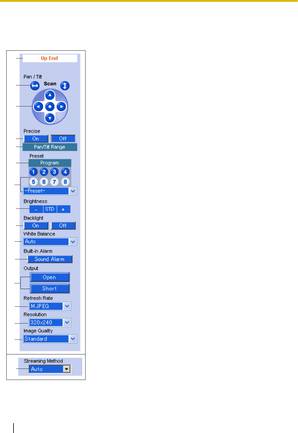
The operation bar is displayed to the left of the camera image when viewing images from a single camera, and
provides the following features.
A
B
C
F
M
N
O
H
I
E
P
G
L
J
D
K
A. End Display and Preset Display: When the lens has reached the end
of its pan or tilt range, the appropriate message will be displayed here
([Left End], [Right End], [Up End], [Down End]. [Additionally, when a
preset (see Page 29) is selected, the name of the preset is displayed
here (except [Home Position]).
B. Pan and Tilt Scan Buttons: Allow you to pan or tilt the lens to its
maximum pan or tilt range (see 1.2.2 Aiming the Camera Lens). The lens
returns to the original position when finished.
C. Navigation Buttons: Allow you to pan the lens left and right, and tilt the
lens up and down (see 1.2.2 Aiming the Camera Lens). Click the center
navigation button to move the lens to the home position.
D. Precise Pan and Tilt On/Off Buttons: Turn the precise pan/tilt feature
on and off. When this feature is turned on, the navigation buttons move
the camera in small increments, allowing precise lens control (see
1.2.2 Aiming the Camera Lens).
E. Pan/Tilt Range Button: Allows you to limit the pan and tilt range of the
camera’s lens (see Page 28).
F. Preset Program Button: Allows you to add, change, or delete presets
(see Page 29).
G. Preset Selection Buttons and Menu: Allow you to move the lens to a
pre-programmed position. You can register up to 8 presets (see
Page 29). Click buttons 1–8 to move the lens to the corresponding
preset, or select the desired preset from the pull-down menu.
H. Brightness Controls: Allow you to change the brightness of the
displayed image. Click [-] to darken the image, [+] to brighten the image,
and [STD] to return the image to the standard brightness level. There are
a total of 9 brightness levels available.
I. Backlight Correction Buttons: Allow you to turn the backlight correction
feature on and off. This feature can automatically correct the contrast in
dark areas of the camera image (see page 31).
J. White Balance Selector: Allows you to adjust the white balance to match
the environment of the camera. Change this setting to achieve the most
natural looking colors (see Page 32).
K. Built-in Alarm Button: Allows you to sound the built-in alarm. You can
set when the built-in alarm sounds, as well as the built-in alarm volume
and the built-in alarm sound type (see Page 174). This button is not
available depending on the [Trigger for Built-in Alarm] setting (see
Page 174).
L. Output Control (BL-C230 Only): Controls the output signals of the
external I/O interface (see Page 168).
24 Operating Instructions
1.2.1 Using the Operation Bar

M. Refresh Rate Selector: Determines whether video images or still images
are displayed. Select [MJPEG], [MPEG-4], or [H.264] to view video
images, or select the refresh rate of still images (JPEG images). For
example, selecting [3 s] will refresh the camera image once every 3
seconds. Whether H.264 or MPEG-4 is available (BL-C210A/
BL-C230A: H.264 is available by default, BL-C210CE/BL-C210E/
BL-C230CE/BL-C230E: MPEG-4 is available by default) depends on the
[Streaming Format] on the [Video Streaming] page (see Page 145).
N. Image Resolution Selector: Determines the resolution of the image (i.e.,
the size of the image in pixels) that is displayed.
O. Image Quality Selector: Allows you to select the image quality. Select
[Favor Clarity] for optimal image clarity, [Favor Motion] for optimal motion
quality, and [Standard] for standard image quality. This selector is not
displayed when [H.264] or [MPEG-4] is selected under [Refresh Rate].
P. Streaming Method Selector: Allows you to select the method used to
stream H.264 or MPEG-4 images from the camera (see Page 33). This
selector is displayed only when [H.264] or [MPEG-4] is selected under
[Refresh Rate]. To stream H.264 or MPEG-4 images using Multicast, you
must first configure the camera for multicasting (see Page 145), after
which [Multicast] is available from this pull-down menu.
Note
•Screen content varies by model number.
•Features that are disabled for general users (see Page 152) or guest users (see Page 155) are not
displayed in the operation bar for those users.
•The brightness, backlight, and white balance settings assigned to the home position are used each
time the camera is turned on, however, the current settings are saved when registering a preset (see
Page 29) and those settings are used when viewing a preset.
•The camera lens moves to the home position when it is turned on. You can change the home position
if necessary (see Page 29).
Operating Instructions 25
1.2.1 Using the Operation Bar
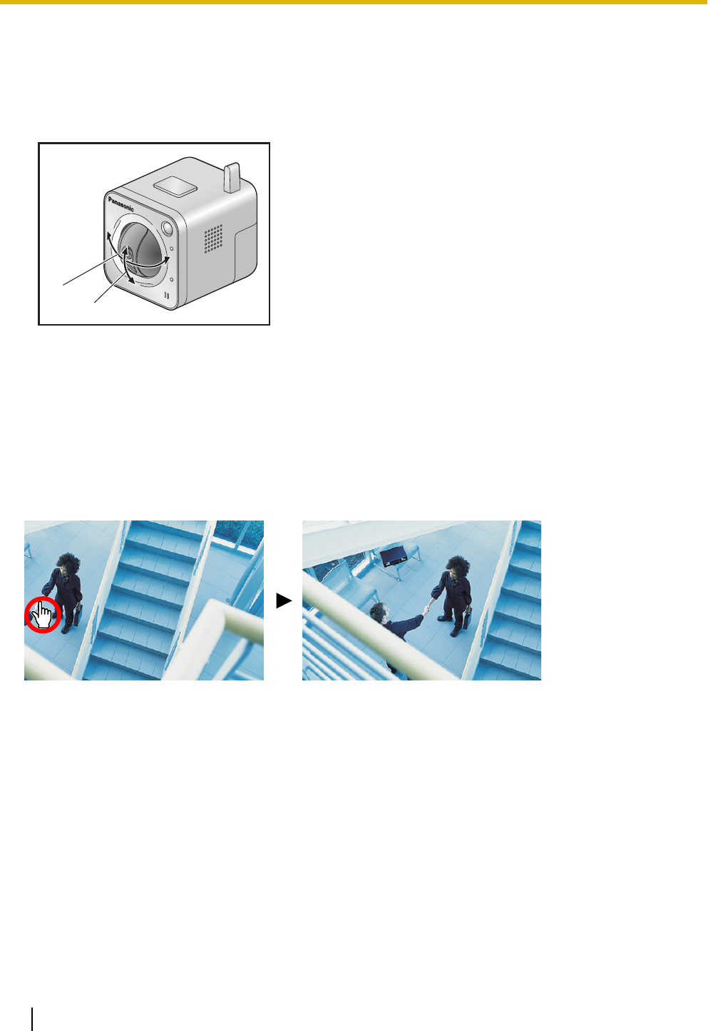
1.2.2 Aiming the Camera Lens
The camera can be panned from -41 ° to +41 ° from the center position, and tilted from -32 ° to +10 ° from the
center position. If the [Pan/Tilt Range] button was used to limit the maximum pan and tilt range of the camera
(see Page 28), the lens can only be moved to the maximum pan or tilt range allowed.
A
B
A. Pan: -41 ° to +41 °
B. Tilt: -32 ° to +10 °
There are several ways you can move the camera lens to view the desired image, as described in this section.
Click to center
Allows you to quickly and easily center the camera image on the desired point. Simply move the mouse cursor
to the desired point in the camera image, and click. Note that the camera may not be able to center on the
clicked point if it is outside of the pan and tilt range of the lens.
This feature can be disabled for general users (see Page 152) and for guest users (see Page 155). Note,
however, that if the click to center feature is disabled, users can still use this feature when using the ActiveX
zoom feature. Users can click to center the image within the zoomed area, but the lens will not pan or tilt.
Pan and tilt scan buttons
Allow you to pan or tilt the lens to its maximum pan or tilt range. The lens returns to the original position when
finished. You can click an area of the camera image to stop the scan operation and center the camera image
on the desired point.
This feature can be disabled for general users (see Page 152) and for guest users (see Page 155).
Navigation buttons
Allow you to pan the lens left and right, and tilt the lens up and down. Click the center navigation button to
move the lens to the home position.
26 Operating Instructions
1.2.2 Aiming the Camera Lens

When the precise pan/tilt feature is turned on (click [On] under [Precise] in the operation bar), the navigation
buttons move the camera in small increments, allowing precise lens control.
•The camera lens moves to the home position when it is turned on. You can change the home position if
necessary (see Page 29).
This feature can be disabled for general users (see Page 152) and for guest users (see Page 155).
Presets
Allow you to move the lens to a pre-programmed position. You can register up to 8 presets (see Page 29).
Click buttons 1–8 to move the lens to the corresponding preset, or select the desired preset from the pull-down
menu. You can also move the lens to the home position by clicking the center navigation button.
This feature can be disabled for general users (see Page 152) and for guest users (see Page 155).
Note
•If the camera is aimed at a preset position while zoomed, the position may vary slightly from the
registered preset position.
Operating Instructions 27
1.2.2 Aiming the Camera Lens
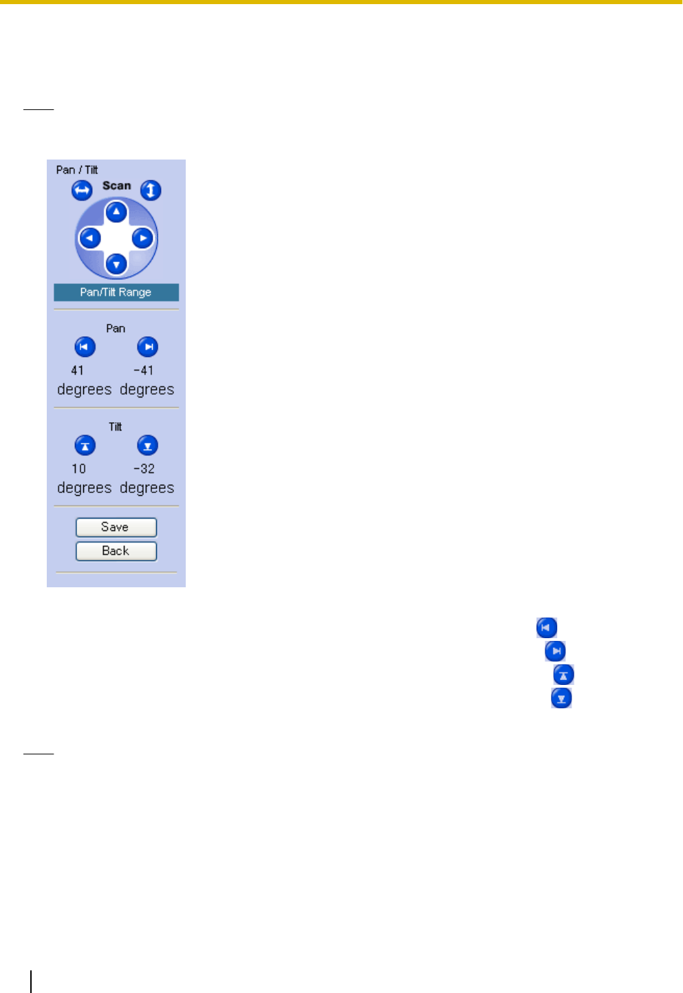
1.2.3 Limiting the Pan/Tilt Range
You can limit the maximum pan and tilt range of the camera’s lens.
Note
•This feature is available to the camera administrator only.
1. Click the [Pan/Tilt Range] button in the operation bar.
2. Set the pan and tilt range as desired.
a. Aim the camera to the leftmost point you want to allow to be seen, then click .
b. Aim the camera to the rightmost point you want to allow to be seen, then click .
c. Aim the camera to the uppermost point you want to allow to be seen, then click .
d. Aim the camera to the lowermost point you want to allow to be seen, then click .
3. Click [Save].
Note
•Even if you limit the pan and tilt range, you can view the entire range of the camera’s pan and tilt range
while setting the pan and tilt range on this page.
•When you click the [Pan/Tilt Range] button, the refresh rate changes to MJPEG.
•You can aim the camera by clicking on the desired navigation button, or by using the click to center
feature.
28 Operating Instructions
1.2.3 Limiting the Pan/Tilt Range

1.2.4 Registering and Changing Presets
Presets allow you to easily aim the camera lens in the desired direction. Brightness, backlight, and white
balance settings are also saved when registering a preset. The following presets can be registered:
•Home position (the direction that the lens moves to when you turn the camera on or click the center
navigator button)
•Sensor position
•Alarm positions 1 and 2
•Presets 1–8
Additionally, the first 4 presets are set by default.
•1: UpperLeft
•2: UpperRight
•3: LowerLeft
•4: LowerRight
Viewing a preset
You can move the lens to a preset position in the following ways:
•Click the center navigator button (to move the lens to the home position)
•Click [-Preset-] and select a preset from the pull-down menu
•Click a blue preset button (1–8) (Unregistered preset buttons are displayed in white.)
Registering or changing a preset
Note
•This feature is available to the camera administrator only.
•Zoom settings are not registered to presets.
1. Confirm that you are logged in to the camera as the administrator.
2. Under [Preset] in the operation bar, click [Program].
3. Aim the camera in the desired direction.
4. Adjust the brightness, backlight, and white balance settings if desired. These settings will be registered to
the preset.
5. Under [Preset Number], select the desired preset from the pull-down menu.
6. Enter a name for the preset (max. 15 characters).
•You cannot rename the home position, sensor position, or alarm positions.
•See Page 206 for a list of valid characters. Note that [Space], ["], ['], [&], [<] and [>] cannot be used.
7. Click [Save] to register the preset, or click [Back] to cancel.
•When [Success!] is displayed, click [Back] to continue.
Deleting a preset
Note
•This feature is available to the camera administrator only.
1. Confirm that you are logged in to the camera as the administrator.
2. Under [Preset] in the operation bar, click [Program].
3. Under [Preset Number], select the desired preset from the pull-down menu.
•You cannot delete the home position or alarm positions.
4. Click [Delete] to delete the preset, or click [Back] to cancel.
•When [Success!] is displayed, click [Back] to continue.
Operating Instructions 29
1.2.4 Registering and Changing Presets

1.2.5 Zooming
The camera supports ActiveX zoom. ActiveX zoom is a digital zoom that is implemented using the ActiveX
software installed on the computer viewing the camera images. It allows you to magnify images by up to 3´.
The zoom feature can be used when:
–Viewing video images on the single camera page
–Viewing video images from multiple cameras on the multi camera page
–Viewing buffered MJPEG video images on the buffered image page
Note
•Zooming is not available when viewing camera images on a mobile phone.
•The zoom magnification (´1.0–´3.0) is displayed briefly while zooming.
•As the magnification increases, image quality decreases.
•When ActiveX zoom is used, only the image seen by the user operating the zoom is zoomed.
•You can move the lens as normal (selecting a preset, using the navigation buttons, etc.) even when
zooming.
Zooming with the scroll wheel
With the cursor placed over the camera image, rotate the scroll wheel away from you to zoom in, and rotate
the scroll wheel toward you to zoom out. Note that the zoom speed depends on your mouse performance and
your PC’s mouse settings.
B
A
A. Zoom in
B. Zoom out
Zooming with the right mouse button
Right-click the upper part of the image to zoom in, and right-click the lower part of the image to zoom out.
A
B
A. Zoom in
B. Zoom out
30 Operating Instructions
1.2.5 Zooming

1.2.6 Backlight Correction
The camera’s backlight correction feature can automatically correct the contrast in dark areas of the camera
image. This means even when there is backlight or a large amount of contrast in the image, the camera can
correct the image to provide a more consistent, natural image. You can turn this feature on and off by clicking
[On] and [Off] under [Backlight] in the operation bar.
Note
•If you select to display the status in the overlay setting, is displayed on the single camera and multi
camera pages when the backlight correction feature is on (see Page 159).
•The backlight setting assigned to the home position is used each time the camera is turned on.
•The current backlight setting is saved when registering a preset (Page 29), and is used when viewing
the preset.
•The effectiveness of this feature may vary depending on the object being viewed and other conditions.
Additionally, under certain conditions, the image may appear unnatural, or noise may appear in the
image when this feature is enabled.
Operating Instructions 31
1.2.6 Backlight Correction

1.2.7 White Balance
While viewing camera images on the single camera page, you can use the [White Balance] selector to adjust
the camera’s image to match the environment of the camera. Change this setting to achieve the most natural
looking colors.
The following settings are available.
–[Auto]: White balance is adjusted automatically according to the image being displayed
–[Indoor]: Electric bulb (2800 K)
–[Fluorescent (White)]: White type fluorescent light (4000 K)
–[Fluorescent (Daylight)]: Daylight type fluorescent light (4800 K)
–[Outdoor]: Solar light (6000 K)
–[Hold]: Maintains the current white balance setting
Note
•“K” (Kelvin) is the unit used to measure color temperature.
•The current white balance setting is saved when you register a preset (see Page 29).
32 Operating Instructions
1.2.7 White Balance

1.2.8 Video Images and Image Refresh Rate
Using the [Refresh Rate] selector in the operation bar, you can select whether video images ([MJPEG],
[MPEG-4], or [H.264]) are displayed, or still images that are refreshed periodically (3 seconds, 5 seconds, etc.)
are displayed. You can change the default setting for [Refresh Rate] that is used each time the single camera
page is accessed (see Page 159).
Certain features are limited depending on the [Streaming Format] setting (see Page 209). Additionally,
[Refresh Rate] selection can be disabled for general users (see Page 152) and for guest users (see
Page 155).
MJPEG
MJPEG (Motion JPEG) is a video format that displays a continuous series of still images. Because each MJPEG
frame is a still image, this format offers high-quality images, but uses more bandwidth, and frame rate may
decrease as a result. To view images in MJPEG format, set the [Refresh Rate] selector to [MJPEG].
MPEG-4
MPEG-4 is a video format that updates images only when there is a variation in the image displayed, and as
a result, requires less bandwidth. MPEG-4 is useful in situations when less bandwidth is available, such as
when viewing camera images over the Internet. To view images in MPEG-4 format, set the [Refresh Rate]
selector to [MPEG-4], then select the desired streaming format under [Streaming Method].
•In order to view images using MPEG-4, [Streaming Format] on the [Video Streaming] page must be set to
[MPEG-4] (see Page 145). When this setting is changed, the camera must be restarted before the new
setting takes effect. When [MPEG-4] is selected, H.264 images cannot be viewed.
H.264
H.264 is a video format that offers high-quality images. Note, however, that the camera does not support
buffering and transferring H.264 images. To view images in H.264 format, set the [Refresh Rate] selector to
[H.264], then select the desired streaming format under [Streaming Method].
•In order to view images using H.264, [Streaming Format] on the [Video Streaming] page must be set to
[H.264] (see Page 145). When this setting is changed, the camera must be restarted before the new setting
takes effect. When [H.264] is selected, MPEG-4 images cannot be viewed.
Video streaming
H.264 and MPEG-4 images can be streamed using multicast, unicast, and HTTP (see Page 145). When
accessing the camera using HTTPS, multicast and unicast streaming is not possible: HTTP is the only available
streaming method.
–[Auto]: The first available streaming method will be used, beginning with multicast, then unicast, then HTTP.
The current streaming method is displayed below the camera image.
–[Multicast] (Multicast RTP): Multicast allows you to stream the same data over the network to multiple
parties, thus reducing the amount of data that is sent over the network.
•Multicast streaming is not possible when viewing camera images over the Internet.
•In order to use multicast streaming, the camera must be configured for multicasting (see Page 145).
Note that multicast streaming is not possible when viewing camera images on certain local networks.
Consult your network administrator before configuring the camera for multicasting.
•Images may break up when accessing the camera over a low bandwidth connection. This is normal.
In this case, select [Unicast] or [HTTP] as the streaming method.
•If images cannot be displayed or if images break up when [Multicast] is selected as the streaming
method, select [Unicast] or [HTTP].
Operating Instructions 33
1.2.8 Video Images and Image Refresh Rate

–[Unicast] (Unicast RTP): While no special settings are required to stream video using unicast, video is
streamed to each individual user viewing video images, which creates more network traffic as more users
access the camera. Unicast is generally more reliable than multicast, and is not as susceptible to image
quality issues that may occur with when multicasting.
•Unicast streaming is not possible when viewing camera images over the Internet.
•Unicast streaming may not be possible when viewing camera images on certain local networks. Consult
your network administrator for more information.
•If a user with a low bandwidth connection or if many users are viewing images using unicast streaming,
frame rate will decrease and image quality may be affected for all users viewing H.264 or MPEG-4
images.
•If images cannot be displayed or if images break up when [Unicast] is selected as the streaming
method, select [HTTP].
–[HTTP]: When streaming video using HTTP, the camera confirms that the data is being received by the
user. Video can be viewed in network environments that do not support multicast or unicast streaming,
however, this streaming method requires more bandwidth than the other methods.
•If a user with a low bandwidth connection or if many users are viewing images using HTTP streaming,
frame rate will decrease and image quality may be affected for all users viewing H.264 or MPEG-4
images.
•If images cannot be displayed when [HTTP] is selected as the streaming method, select [MJPEG] as
the image refresh rate.
•When [HTTP] is selected, HTTP is used when viewing H.264 images, and RTP over HTTP is used
when viewing MPEG-4 images.
Note
•If a user with a low bandwidth connection is viewing H.264 or MPEG-4 images, frame rate will decrease
and image quality may be affected for all users viewing H.264 or MPEG-4 images.
•When the camera is configured to buffer images in H.264 or MPEG-4 format, frame rate will decrease
when viewing H.264 or MPEG-4 images on the single camera and multi camera pages.
•To adjust video streaming settings in order to improve image quality or frame rate when viewing H.264
or MPEG-4 images, see Page 145.
•BL-C230 only: When in wireless mode, Multicast may not work properly because the IEEE 802.11
standard limits the bandwidth. Select [Unicast] or [HTTP] as the streaming method.
Still images
Still images that are refreshed periodically can be displayed instead of video images by selecting the desired
refresh rate. For example, selecting [3 s] will refresh the camera image once every 3 seconds.
34 Operating Instructions
1.2.8 Video Images and Image Refresh Rate

1.2.9 Taking Snapshots
You can take snapshots while viewing camera images and save them on your PC.
1. Click the snapshot button ( ).
•The camera image opens in a new window.
2. Right-click the image, and select [Save Picture As...].
•The [Save Picture] dialog appears.
3. Enter a name for the file.
4. Specify where you want to save the file, then click [Save].
5. Click [Close].
Note
•Snapshots are saved in JPEG format at the [Favor Clarity] setting.
•This feature can be disabled for general users (see Page 152) and for guest users (see Page 155).
Operating Instructions 35
1.2.9 Taking Snapshots

1.2.10 Audio Features
While viewing live images from the camera, you can monitor the audio from the camera’s microphone.
1. Confirm that the listen button ( ) is displayed.
•You can mute the audio by pressing the listen button. It will change to the listen off button ( ).
•Press the listen off button to monitor the audio again.
2. Adjust the volume using the volume slider ( ).
•When viewing H.264 or MPEG-4 images, the volume slider changes appearance ( ).
Note
•This feature can be disabled for general users (see Page 152) and for guest users (see Page 155).
•The audio may be interrupted or delayed due to your PC’s performance, the network environment, if
you are running other applications, or if you have multiple windows open. Close other applications and
windows or reduce the maximum bandwidth (see Page 113 or Page 190) for best performance.
•By default the camera’s microphone is automatically muted when the lens is panning or tilting. You can
change this setting if desired, as well as adjust the sensitivity of the microphone (see Page 144).
•When the image is refreshed (such as during preset registration or when clicking your browser’s refresh
button), the volume is reset to the center position and the mute will be turned off (i.e., audio will be
heard again).
•If you experience difficulty when using audio features, refer to 1.10 Audio Issues in the Troubleshooting
Guide.
36 Operating Instructions
1.2.10 Audio Features

1.2.11 Additional Features Available While Viewing Live Camera
Images
The following features are available while viewing live camera images. These features utilize the ActiveX
software installed on the computer that is used to view camera images, and are therefore set individually for
each computer. The features that can be used vary depending on the current image format (MJPEG, MPEG-4,
H.264).
–Detection notification sound (available for MJPEG images only)
While viewing MJPEG images on the single camera or multi camera page, your computer can play a sound
to notify you when motion is detected or when the sensor is triggered (see Page 37).
–Image display method (not available for H.264 images)
Determines which image display method is used by the computer to display camera images (see
Page 39).
–Software color night view
Brightens the camera image (see Page 41).
Detection notification sound
Available when viewing MJPEG images only.
While viewing MJPEG images on the single camera page and the multi camera page, your computer can play
a sound to notify you when motion is detected or when the sensor is triggered.
This feature can be set independently on each computer that accesses the camera, and functions whether the
triggers on the camera’s [Buffer/Transfer] page are active or disabled. When viewing images on the multi
camera page, it can be set independently for each camera image.
Operating Instructions 37
1.2.11 Additional Features Available While Viewing Live Camera Images
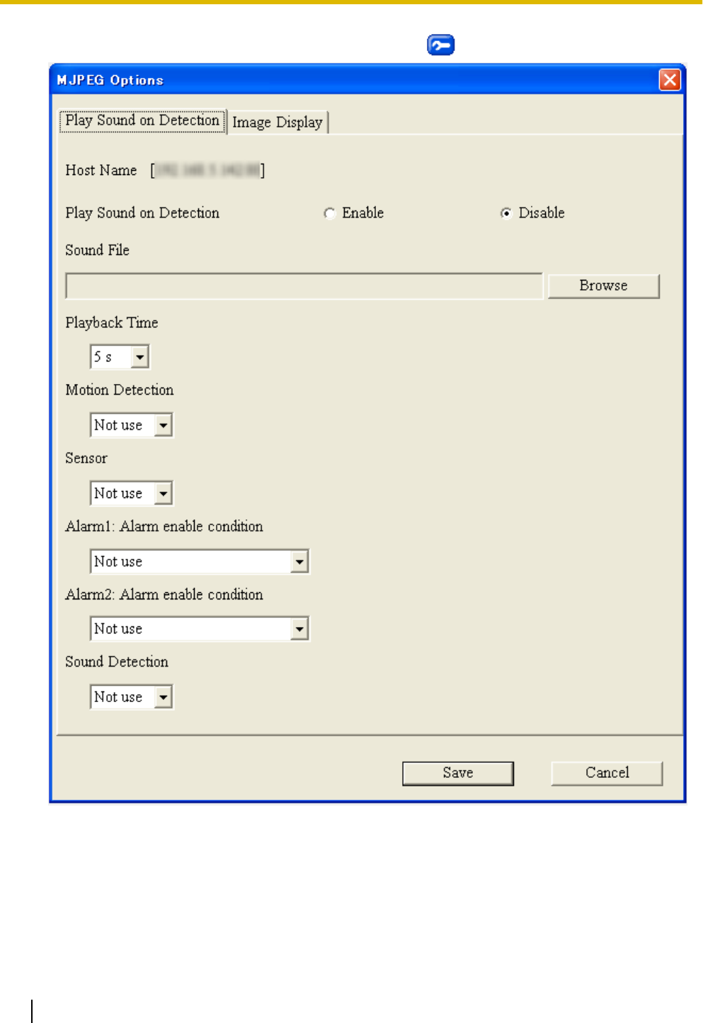
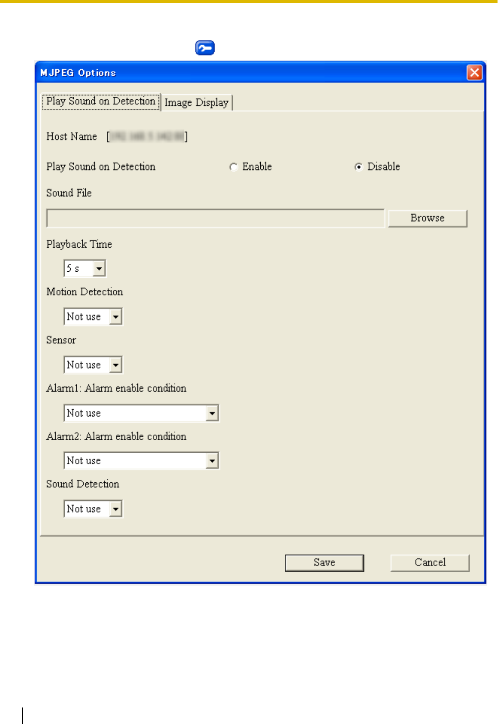
1. While viewing the single camera or multi camera page, click .
2. Set the following parameters as desired.
a. Next to [Play Sound on Detection], select whether you want your computer to play a sound to notify
you when motion is detected or when the sensor is triggered.
b. Under [Sound File], click [Browse], then select the desired sound (audio file).
•Only PCM-format .wav files are compatible with this feature.
•Only files that are less than 10 seconds long are compatible with this feature.
c. Under [Playback Time], select the desired playback time.
d. Select whether you want your computer to play a sound to notify you when there is a detection.
38 Operating Instructions
1.2.11 Additional Features Available While Viewing Live Camera Images
3. Click [Save].
4. Click your web browser’s refresh button to apply the new settings.
Note
•You can set the detection notification sound feature for each camera viewed on the multi camera page,
however, this feature is not available when [16 Screens] is selected.
•Sample audio files can be found in the [AudioSample] folder on the CD-ROM.
Image display method
You can select the image display method used to display motion images on the single camera page and the
multi camera page. Adjust this setting if motion images are not smooth or if frames are dropped.
This feature is set independently on each computer that accesses the camera. It affects all camera images
displayed on the multi camera page and cannot be set independently for each camera.
Note
•Using this feature may cause frame rate to decrease and may increase the CPU usage. If this occurs,
try changing the [Image Display Method] setting.
When viewing H.264 images
When viewing H.264 images, the image display method is DirectShow® and cannot be changed.
When viewing MPEG-4 images
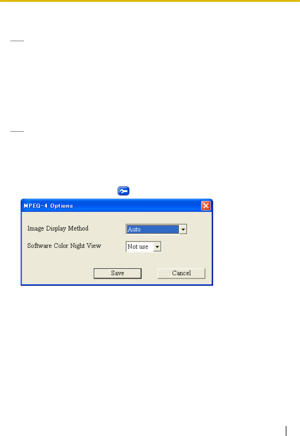
1. While viewing camera images, click .
2. Next to [Image Display Method], select the desired method.
•Options available for this setting vary depending on the operating system and other software installed
on the computer.
•When [Auto] is selected when using Windows Vista, GDI is used. When using Windows® XP,
DirectDraw® is used.
3. Click [Save].
Operating Instructions 39
1.2.11 Additional Features Available While Viewing Live Camera Images
When viewing MJPEG images
1. While viewing camera images, click .
40 Operating Instructions
1.2.11 Additional Features Available While Viewing Live Camera Images
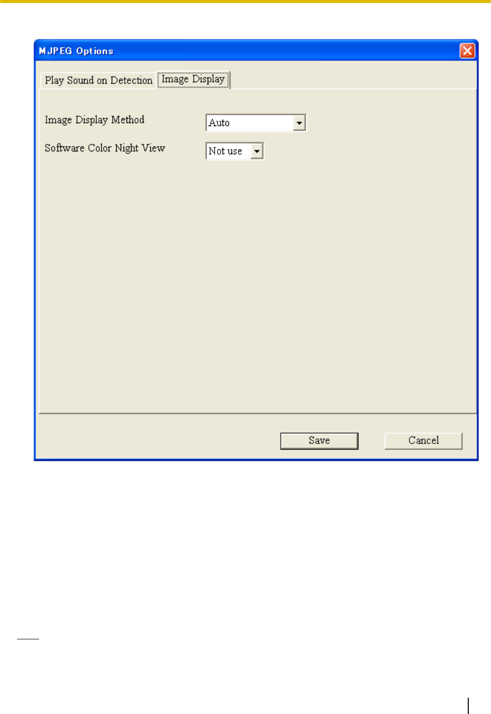
2. Click the [Image Display] tab.
3. Next to [Image Display Method], select the desired method.
•Options available for this setting vary depending on the operating system and other software installed
on the computer.
•When [Auto] is selected when using Windows Vista, GDI is used. When using Windows XP,
DirectDraw is used.
4. Click [Save].
Software color night view
You can set the computer to brighten motion images displayed on the single camera page. (Page 210)
This feature is set independently on each computer that accesses the camera. It affects all camera images
displayed on the multi camera page and cannot be set independently for each camera.
Note
•If frame rate decreases, this feature may not perform as expected.
Operating Instructions 41
1.2.11 Additional Features Available While Viewing Live Camera Images
•Frame rate decreases when the camera’s color night view feature is active (see Page 142), and as a
result, this feature may not perform as expected.
•Using this feature may cause frame rate to decrease and may increase the CPU usage.
•When taking snapshots while this feature is enabled, the camera image is not brightened in the
captured snapshots.
•When viewing H.264 or MPEG-4 images, the computer’s performance may not be adequate to use
software color night view, and images may break up as a result. In this case, turn off software color
night view and try using the camera’s color night view mode feature (see Page 142).
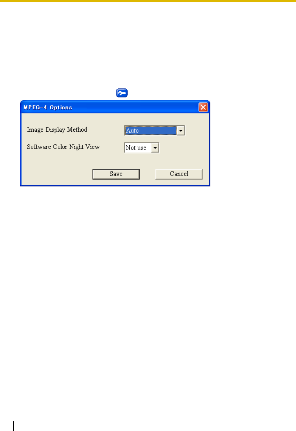
When viewing H.264 or MPEG-4 images
1. While viewing camera images, click .
2. Next to [Software Color Night View], select the desired setting.
3. Click [Save].
42 Operating Instructions
1.2.11 Additional Features Available While Viewing Live Camera Images
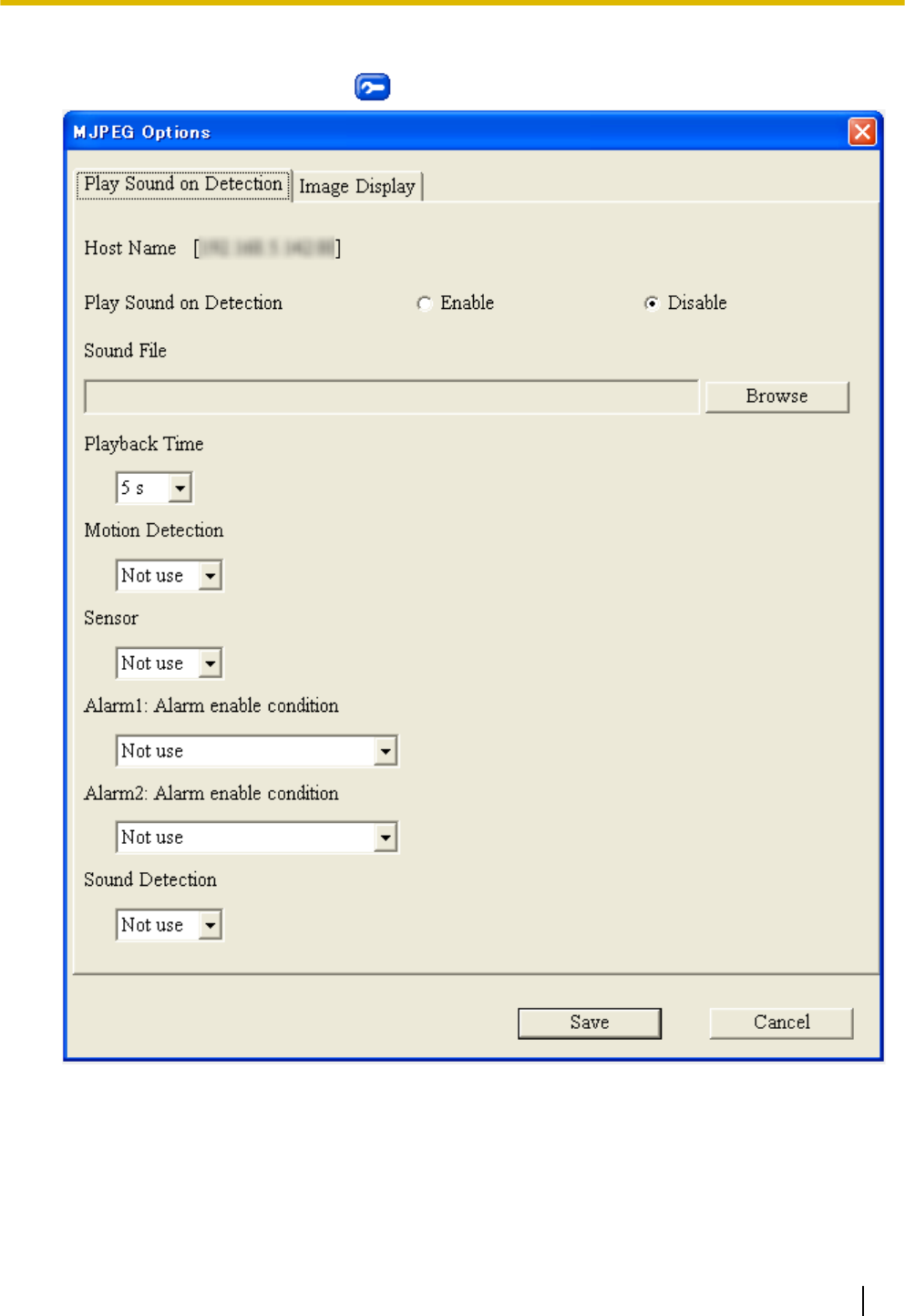
When viewing MJPEG images
1. While viewing camera images, click .
Operating Instructions 43
1.2.11 Additional Features Available While Viewing Live Camera Images
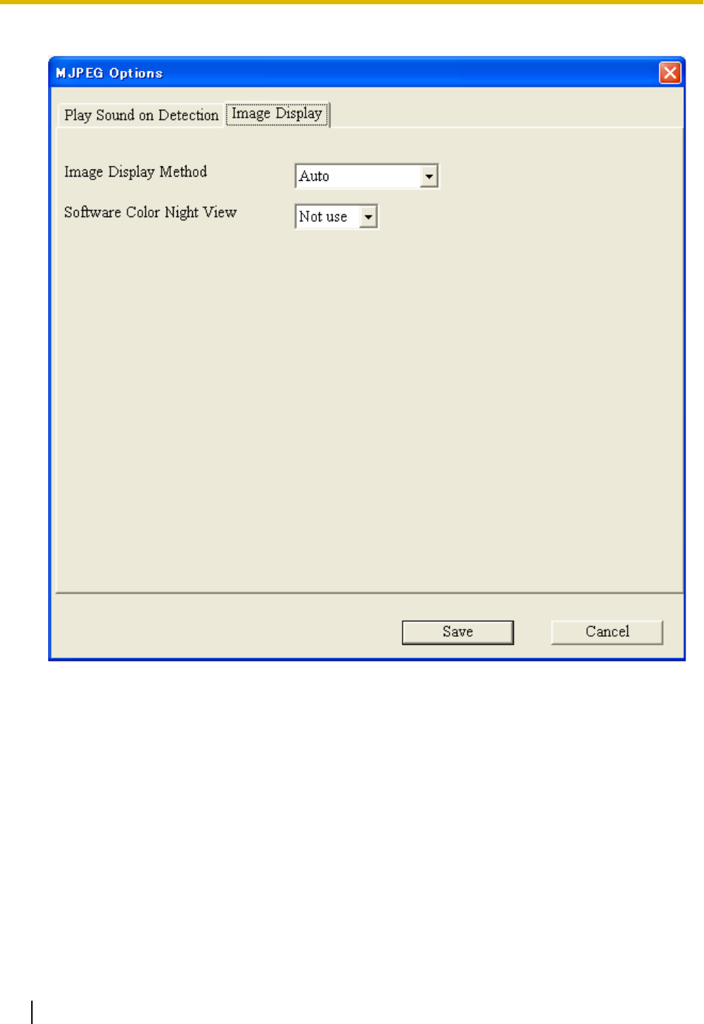
2. Click the [Image Display] tab.
3. Next to [Software Color Night View], select the desired setting.
4. Click [Save].
44 Operating Instructions
1.2.11 Additional Features Available While Viewing Live Camera Images
1.3 Viewing Multiple Camera Images
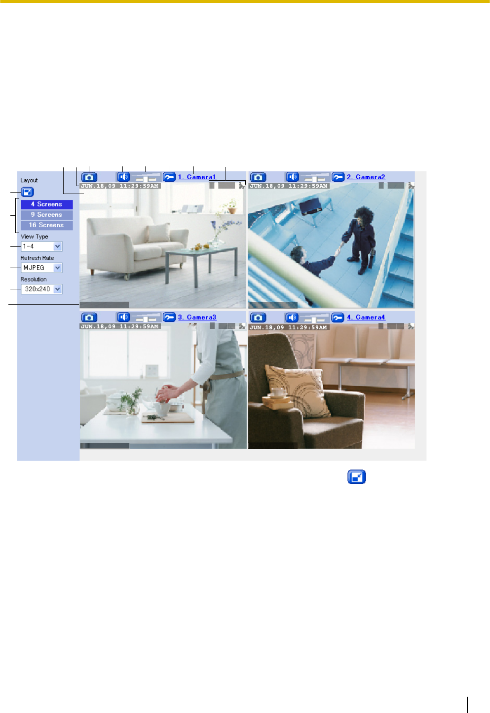
You can register other Panasonic Network Cameras to this camera (see Page 163) and use the multi camera
page to view images from multiple cameras. After you have registered the other cameras to this camera (up
to 16 cameras can be registered), follow the procedure below to view camera images.
1. Access the camera (see Page 8).
2. Click the [Multi] tab.
The multi camera page
Text Overlay Text Overlay
Text Overlay Text Overlay
O MS12 O MS12
O MS12 O MS12
C
D
E
GH J K L N
B
A
F
IM
A. Full-screen button (click to view the image in 4:3 full-screen mode; click to return to normal mode)
B. Changes the number of cameras displayed
C. Switches the display to a different set of cameras
D. Determines the video format of images displayed, or how often the camera images are refreshed
E. Determines the resolution (i.e., the number of pixels) that are displayed for each image
F. Text overlay (see Page 159)*1
G. Camera image (click an area of the camera image to use the click to center feature (see Page 26)*4, or use
your mouse to use the zoom feature when displaying images)
H. Date and time overlay (see Page 159)*1
I. Snapshot button (see Page 35)
J. Listen button*2 (see Page 36)
K. Volume slider*2 (see Page 36)
L. Additional Features button (see page 37).*3
M. Camera name (see Page 163; click to view the selected camera’s image in a new window)
Operating Instructions 45
1.3 Viewing Multiple Camera Images

N. Status overlay (see Page 159)*1*5
*1 Overlays are displayed only if they are configured for the camera (see Page 159). For other cameras, overlays cannot be displayed
if the other cameras do not support the overlay feature.
*2 The audio controls displayed for other cameras depend on the audio features supported by the other cameras.
*3 If the camera does not support detection notification sounds, this feature is not available.
*4 If the camera does not support pan and tilt features, this feature is not available.
*5 When viewing images at 192 ´ 144 pixel resolution, status overlay is not displayed.
Note
General Information
•When viewing images on the multi camera page, the maximum image resolution available is 320 ´
240.
•When [16 Screens] is selected as the number of cameras displayed, all images are displayed in
192 ´ 144 pixel resolution, images are displayed as still images, and the audio controls are not
displayed.
•The ActiveX zoom feature (see 1.2.5 Zooming) is available when viewing video images.
•H.264 or MPEG-4 images displayed on the multi camera page are streamed using the HTTP protocol.
•If a camera configured for the multi camera page is configured to not allow access from guest users,
an authentication dialog will be displayed for that camera. You will need to enter a valid user name and
password in order to view images from that camera.
•If a camera displayed on the multi camera page is configured to not allow general users or guest users
to access certain features (audio, pan/tilt, etc.), those features are not available and their corresponding
buttons or controls will not be displayed.
•The image refresh rate may vary depending on network conditions, PC performance, the number of
people accessing the cameras, and the type of objects being viewed.
•When viewing video images, we recommend connecting the cameras using an Ethernet switching hub
instead of a repeater hub to improve image refresh rate.
•As a general guideline, about 3 to 4 Mbps of bandwidth are required to display 4 camera images. If
you do not have enough bandwidth, the refresh rate may decrease when viewing MJPEG images and
image quality may deteriorate when viewing H.264 or MPEG-4 images.
•If audio features are disabled for the camera (see Page 144) or for certain users (see Page 152 or
Page 155), the listen buttons may be displayed, but the audio features cannot be used.
•If you register a camera that does not support H.264 to the multi camera page of a camera that supports
H.264, only MJPEG images from the camera that does not support H.264 can be viewed.
•If you register a camera that supports H.264 to the multi camera page of a camera that does not support
H.264, only MJPEG images from the camera that supports H.264 can be viewed.
Related settings
•The default settings for [Refresh Rate] and [Resolution] that are used each time the multi camera page
is accessed can be changed (see Page 159).
•Image quality for MJPEG and still images cannot be changed directly on the multi camera page. This
setting is determined on the [Image Display] page (see Page 159).
•To reduce data traffic when other users are accessing the camera, you can configure the camera to
automatically switch from displaying video images to still images. Set the [Video Display Time] for
general users (see Page 152) and for guest users (see Page 155).
•When the refresh rate is too slow, you may be able to improve the refresh rate by limiting the bandwidth
(see Page 113 or Page 190).
When a camera image is not displayed
•Confirm the settings on the multi camera setup page (see Page 163).
46 Operating Instructions
1.3 Viewing Multiple Camera Images

•When configuring cameras for the multi camera page, make sure that the cameras you want to access
from the Internet have been registered to this camera using their global IP addresses. For Internet access,
local IP addresses (such as 192.168.xxx.xxx) cannot be used.
Operating Instructions 47
1.3 Viewing Multiple Camera Images

1.4 Maximum Number of Viewing Sessions
The maximum number of users (including Network Camera Recorder software connections) that can view live
and buffered camera images depends on the factors described below. Additional users will see a gray or black
screen.
The maximum number of viewing sessions depends on:
–The connection method (HTTP or HTTPS; see 5.2 HTTPS Settings)
–The [Max. No. of HTTP Sessions] and [Max. No. of HTTPS Sessions] settings (see 5.8 Changing Video
Streaming Settings)
–The [Streaming Format] setting (see 5.8 Changing Video Streaming Settings)
–The image format of the images being viewed
When the connection method is HTTP
Streaming Format Image Format Max. No. of
Users
Total No. of Users
(Regardless of Image Format)
H.264+MJPEG H.264 2 (Default: 2)
Max. 5
MJPEG 5 (Default: 3)
MPEG-4+MJPEG MPEG-4 4 (Default: 3)
Max. 10
MJPEG 10 (Default: 5)
When the connection method is HTTPS
Streaming Format Image Format Max. No. of
Users
Total No. of Users
(Regardless of Image Format)
H.264+MJPEG H.264 2 (Default: 2)
Max. 5
MJPEG 5 (Default: 3)
MPEG-4+MJPEG MPEG-4 2 (Default: 2)
Max. 5
MJPEG 5 (Default: 3)
Note
•As the number of users accessing the camera increases, the following may occur.
–It may take more time before the camera image is displayed.
–Frame rate may decrease.
–Audio may be interrupted.
–Images may be buffered at a slower rate than specified by the [Image Buffer Frequency] setting.
48 Operating Instructions
1.4 Maximum Number of Viewing Sessions

1.5 Maximum Number of Viewing Sessions in
Wireless Mode (BL-C230 Only)
When in wireless mode, because the IEEE 802.11 standard limits the bandwidth, set the maximum number of
users (including Network Camera Recorder software connections) that can view live and buffered camera
images according to the table below.
The maximum number of viewing sessions depends on:
–The [Streaming Format] setting (see 5.8 Changing Video Streaming Settings)
–The image format of the images being viewed
In a bad wireless connection, even if you set the maximum number of sessions smaller than these numbers,
the image refresh rate may decrease and images may break up or not be displayed.
When the connection method is HTTP
Streaming Format Image Format
Max. No. of Users*1
Pattern 1 Pattern 2 Pattern 3
H.264+MJPEG H.264 1 2 –
MJPEG 2 0 –
MPEG-4+MJPEG MPEG-4 1 2 3
MJPEG 5 3 1
When the connection method is HTTPS
Streaming Format Image Format
Max. No. of Users*1
Pattern 1 Pattern 2
H.264+MJPEG H.264 1 2
MJPEG 2 0
MPEG-4+MJPEG MPEG-4 1 2
MJPEG 4 3
*1 When the resolution is 640 ´ 480 and the image quality is Standard in a good wireless connection
Operating Instructions 49
1.5 Maximum Number of Viewing Sessions in Wireless Mode (BL-C230 Only)

2 Using Triggers to Buffer and Transfer Images
The camera can be configured to buffer its images, i.e., save camera images temporarily in its memory. You
can view these images later when accessing the camera. The camera can also be configured to transfer
camera images by E-mail, FTP, or HTTP.
Before you can configure the camera to buffer images, you need to decide what method the camera will use
to buffer or transfer images. Buffering methods are called “triggers”; up to 5 triggers can be configured. Camera
images can be buffered or transferred based on the following triggers:
–Timer
Camera images can be buffered or transferred at specific times on specific days.
–Built-in sensor (pyroelectric infrared sensor)
Camera images can be buffered or transferred when the camera’s built-in sensor is triggered. The active
time of the camera’s sensor can also be specified.
–Alarm (i.e., external sensors)
Camera images can be buffered or transferred when the camera’s external sensors are triggered. The
active time of the camera’s sensors can also be specified.
–Motion Detection
Camera images can be buffered or transferred when the camera detects motion in the camera image. The
active time of the camera’s motion detection feature can also be specified.
–Sound Detection
Camera images can be buffered or transferred when the camera detects sound in the camera image. The
active time of the camera’s sound detection feature can also be specified.
Note
•The built-in sensor cannot make detections for about 30 seconds after the camera is turned on.
•When privacy mode is turned on (see Page 170), camera images are not buffered or transferred.
•H.264 images cannot be buffered or transferred.
•Timer: MPEG-4 images cannot be transferred; they can only be buffered.
Sensor, Alarm, or Detection: Only JPEG images can be buffered or transferred.
•The image buffering and transferring features, the built-in sensor, and the detection features are not
designed to be used for security or surveillance. No responsibility will be taken by our company with
respect to consequences resulting from the use of these features.
•The camera does not use encryption when sending user names and passwords to FTP, E-mail, or
HTTP servers. Use caution as necessary to prevent disclosure of this information.
•For added security, we recommend periodically changing the user names and passwords that are
required to access your FTP, E-mail, and HTTP servers.
•Refer to Page 207 for the camera’s memory capacity for buffering images.
•If the camera is triggered and begins buffering or transferring images, it cannot be triggered again until
the camera stops buffering or transferring images, as shown in the figure below.
The camera can be triggered.
The camera is buffering or transferring images and cannot be triggered during this time.
AB
AThe camera is triggered. Buffering or transferring begins.
BBuffering or transferring ends.
Follow the procedures in this section to configure the camera to buffer or transfer images.
50 Operating Instructions
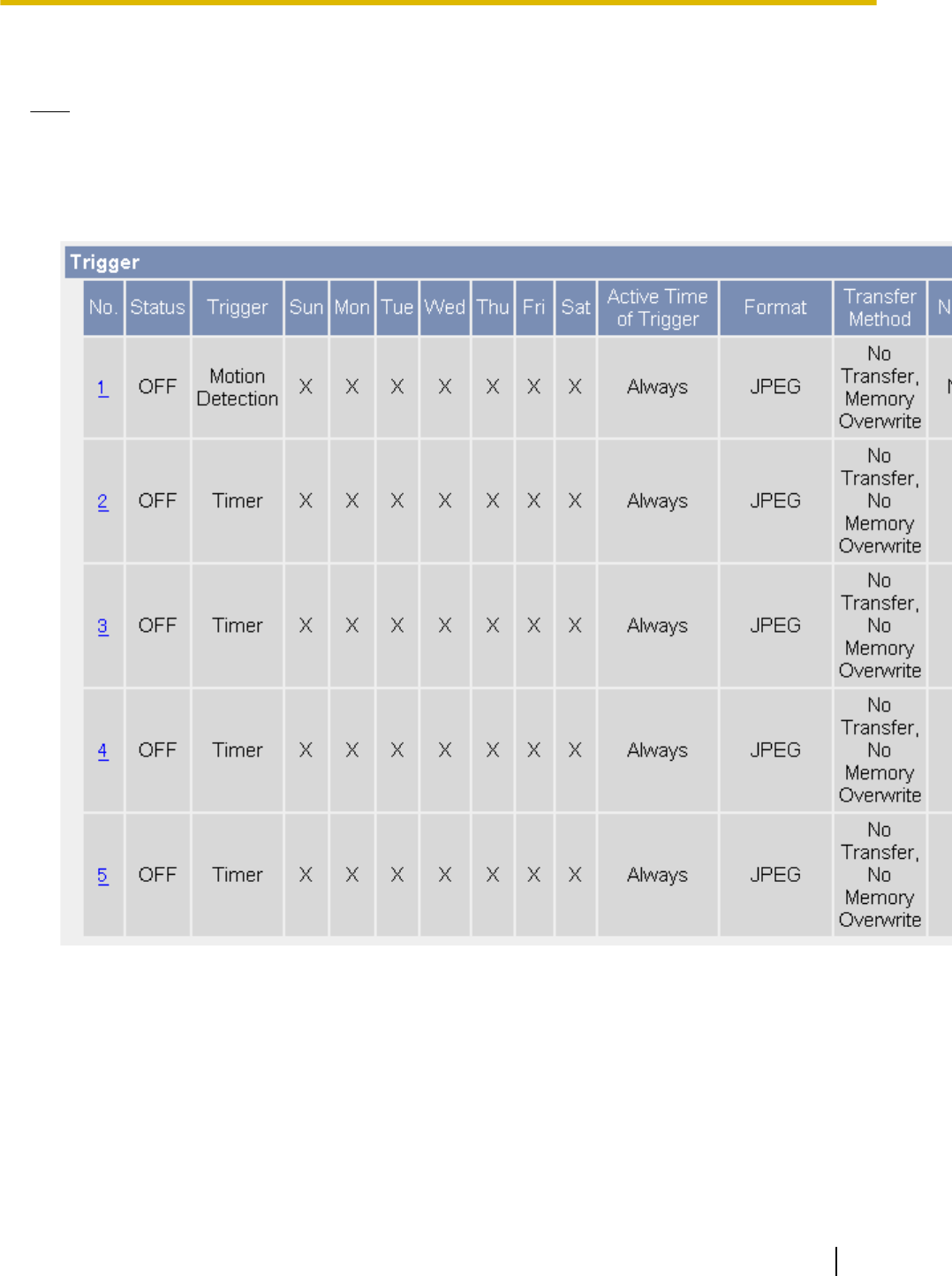
2.1 Configuring a Timer Trigger
Note
•When you change settings for a trigger, all images buffered in the memory for the selected trigger are
deleted. Additionally, images buffered for other triggers may also be deleted. See Page 79 for more
information.
1. Click the [Setup] tab.
2. On the left side of the screen under [Buffer/Transfer], click [Trigger].
Operating Instructions 51
2.1 Configuring a Timer Trigger
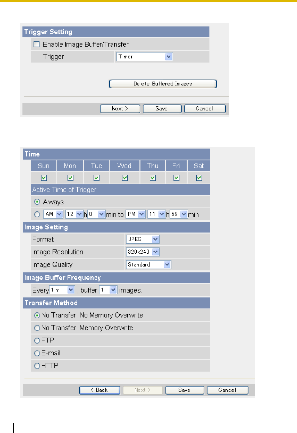
3. Click a trigger number (1–5).
4. Check [Enable Image Buffer/Transfer] to enable the trigger.
5. Select [Timer] from the pull-down menu, then click [Next] to make additional settings (explained below), or
click [Save] to finish.
52 Operating Instructions
2.1 Configuring a Timer Trigger

6. Set the following parameters as desired.
a. Under [Time], select the days of the week when the trigger will be active.
b. Select the time of day the trigger will be active, or click [Always] to enable the trigger for the full 24
hours of each day selected.
c. Under [Image Setting], select the desired image format, image resolution, and image quality.
•When [MPEG-4] is selected, the buffered MPEG-4 file contains audio from the camera’s
microphone if the microphone is enabled.
•The image quality setting is not available when [MPEG-4] is selected as the image format.
•When configuring the trigger to transfer images to a mobile phone’s E-mail address, set the image
resolution to 192 ´ 144, and set the image quality to [Favor Motion]. Note that your mobile phone
may not be able to receive the image if the file size of the image is too large.
•Only one MPEG-4 timer can be set to buffer images at a time.
d. Under [Image Buffer Frequency], select the desired buffer or transfer rate.
•This setting is not available when [MPEG-4] is selected as the image format.
e. Under [Transfer Method], select the desired buffer or transfer method.
•MPEG-4 images cannot be transferred.
•If [MPEG-4] is selected as the image format, [No Transfer, No Memory Overwrite] is the only
available option.
–[No Transfer, No Memory Overwrite]: Images are not transferred. Images are buffered until the
memory is full.
–[No Transfer, Memory Overwrite]: Images are not transferred. Once the memory is full, new images
replace the old images.
–[FTP]: After an image is captured, it is transferred to the specified FTP site.
–[E-mail]: After an image is captured, it is sent to the specified E-mail address.
–[HTTP]: After an image is captured, it is transferred to the specified website.
7. Follow the procedure below based on the settings you made under [Transfer Method].
a. If you selected to not transfer images (i.e., to buffer images only), click [Save] to finish.
•All images buffered in the internal memory for the selected trigger are deleted when you click
[Save].
b. If you selected to transfer images by FTP, E-mail, or HTTP, click [Next].
•The appropriate transfer settings page is displayed.
–For FTP transfer, see Page 61.
–For E-mail transfer, see Page 63.
–For HTTP transfer, see Page 66.
Note
•In order for this feature to work as expected, make sure the camera’s date and time setting is correct
(see Page 140).
•When selecting the buffer or transfer rate, keep in mind that the actual rate may be slower depending
on network conditions, the number of people accessing the camera, and the type of objects being
viewed.
•When the camera is configured to buffer images in MPEG-4 format, frame rate will decrease when
viewing MPEG-4 images on the single camera and multi camera pages.
Operating Instructions 53
2.1 Configuring a Timer Trigger
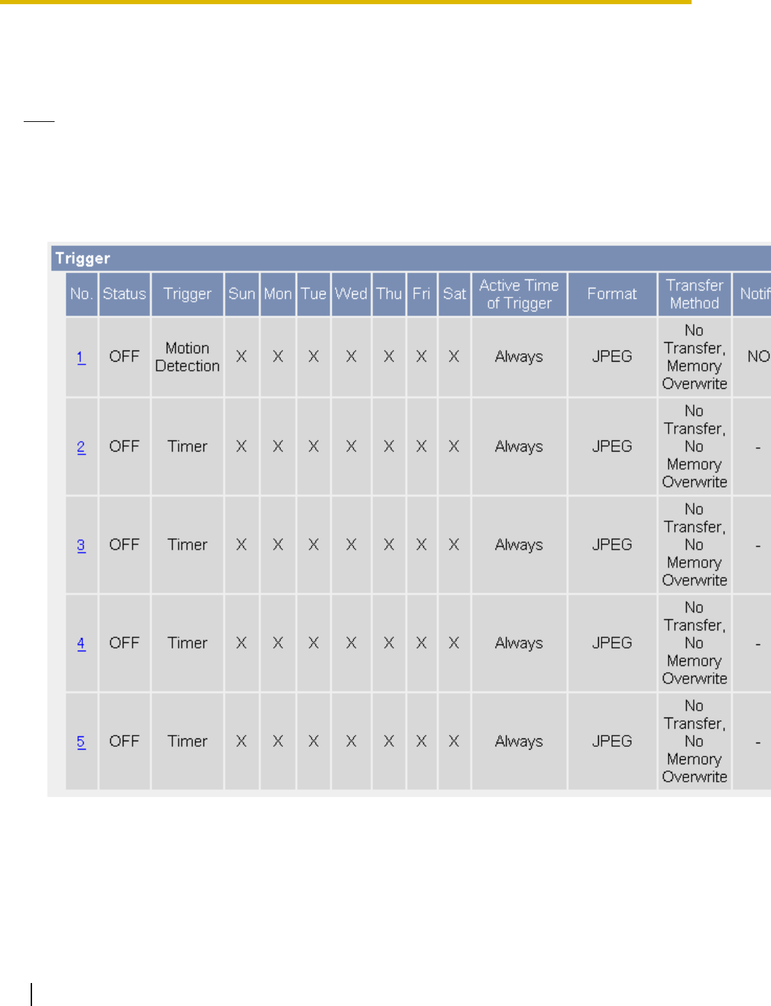
2.2 Configuring a Sensor, Alarm, or Detection
Trigger
Note
•When you change settings for a trigger, all images buffered in the memory for the selected trigger are
deleted. Additionally, images buffered for other triggers may also be deleted. See Page 79 for more
information.
•Only JPEG images can be buffered or transferred.
1. Click the [Setup] tab.
2. On the left side of the screen under [Buffer/Transfer], click [Trigger].
54 Operating Instructions
2.2 Configuring a Sensor, Alarm, or Detection Trigger
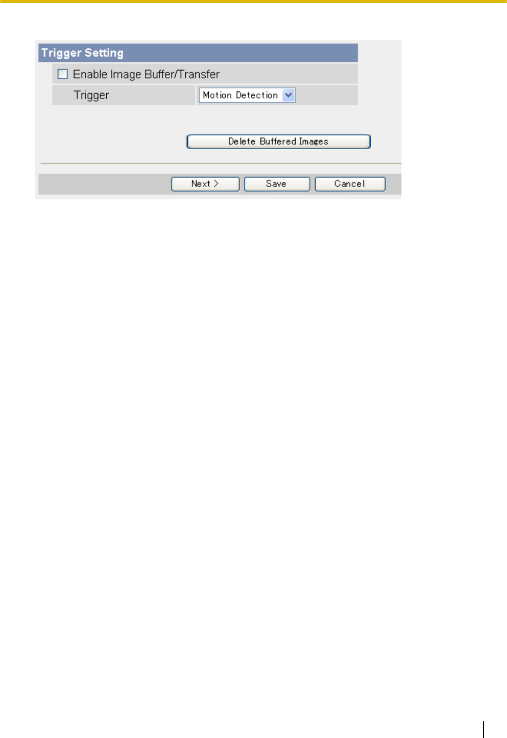
3. Click a trigger number (1–5).
4. Check [Enable Image Buffer/Transfer] to enable the trigger.
5. Select [Sensor], [Alarm1], [Alarm2], [Motion Detection], or [Sound Detection] from the pull-down menu,
then click [Next].
•To adjust the sensitivity of the built-in sensor, see Page 81.
•If [Alarm1] or [Alarm2], is selected, select [Rising: GND to Open (High).] (logical HIGH) or [Falling:
Open (High) to GND.] (logical LOW) for the switching characteristics of the sensor. See the Installation
Guide for details.
•For information on how the motion detection feature detects motion and how to adjust the sensitivity
of the motion detection feature, see Page 82.
•For information on how the sound detection feature detects sound and how to adjust the sensitivity of
the sound detection feature, see Page 84.
Operating Instructions 55
2.2 Configuring a Sensor, Alarm, or Detection Trigger
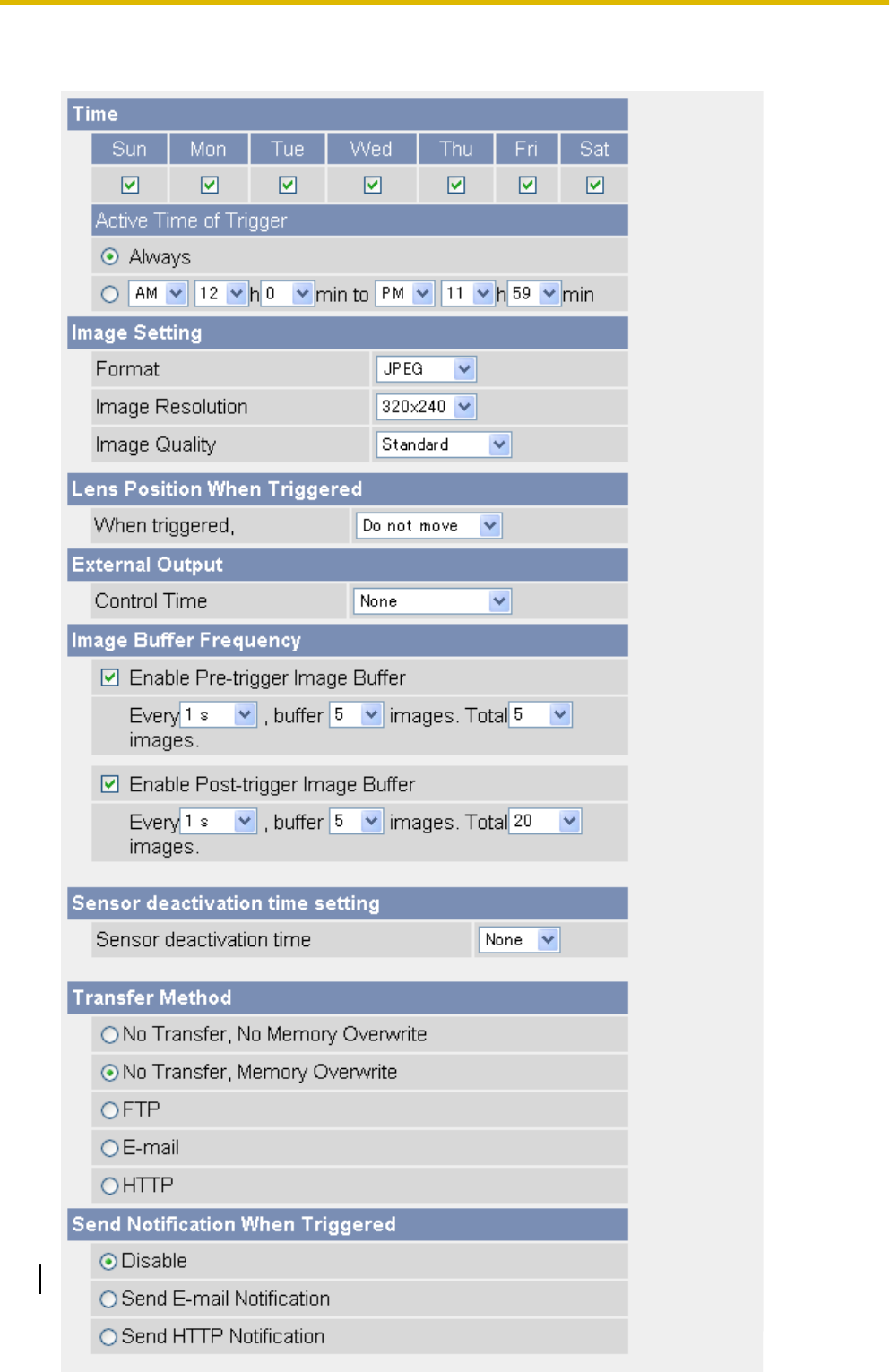
•The motion detection feature is disabled when panning and tilting the camera lens, i.e., moving the
camera lens will not trigger the motion detection feature.
56 Operating Instructions
2.2 Configuring a Sensor, Alarm, or Detection Trigger

6. Set the following parameters as desired.
a. Under [Time], select the days of the week when the trigger will be active.
b. Select the time of day the trigger will be active, or click [Always] to enable the trigger for the full 24
hours of each day selected.
c. Under [Image Setting], select the desired image resolution and image quality.
•When configuring a sensor, alarm, or detection trigger, only JPEG images can be buffered or
transferred.
•When configuring the trigger to transfer images to a mobile phone’s E-mail address, set the image
resolution to 192 ´ 144, and set the image quality to [Favor Motion]. Note that your mobile phone
may not be able to receive the image if the file size of the image is too large.
d. Under [Lens Position When Triggered], select [Do not move] or the desired preset. The lens will aim
in the appropriate direction when triggered.
•Image buffering or transferring begins after the lens has moved to this position.
e. BL-C230 only: Under [External Output], select the desired length of time for which the output terminals
of the external I/O interface are turned on when the camera has been triggered.
f. Under [Image Buffer Frequency], select the desired buffer or transfer rate.
To configure the camera to buffer or transfer images from before the camera was triggered, click
[Enable Pre-trigger Image Buffer] and select the image buffer or transfer rate and the total number of
images to be buffered or transferred. This setting allows you to see camera images leading up to the
moment when the camera was triggered.
To configure the camera to buffer or transfer images from after the camera was triggered, click [Enable
Post-trigger Image Buffer] and select the image buffer or transfer rate and the total number of images
to be buffered or transferred. This setting allows you to see camera images beginning from when the
camera was triggered.
•The image buffer rate may decrease when buffering images.
g. Under [Sensor deactivation time setting], select the amount of time that must pass after a detection
before this trigger can make another detection.
•If the camera is triggered often, many images will be buffered or transferred. If those images are
transferred to a mobile phone by E-mail, for example, many messages will be sent and mobile
phone charges may become expensive. It is therefore recommended to use this setting to help
reduce the number of images that are buffered or transferred.
•Images will not be buffered or transferred during the deactivation time. As a result, pre-buffer
images from the next detection may not be buffered or transferred. For example, if this parameter
is set to [10 s], and if the camera is configured to buffer 1 image per second and store 10 images
before detection (i.e., buffer images for 10 seconds), the camera will not buffer or transfer images
if it is triggered within 10 seconds of the previous trigger. Images can only be buffered or transferred
10 seconds after the previous trigger.
The camera can be triggered.
The camera is buffering or transferring images and cannot be triggered during this time.
Deactivation time; the camera cannot be triggered.
ABC
AThe camera is triggered. Buffering or transferring begins. No new images will be buffered or
transferred.
BBuffering or transferring ends, deactivation time starts. No new images will be buffered or
transferred.
CDeactivation time ends. The camera can buffer or transfer images again.
Operating Instructions 57
2.2 Configuring a Sensor, Alarm, or Detection Trigger

h. Under [Transfer Method], select the desired transfer method.
–[No Transfer, No Memory Overwrite]: Images are not transferred. Images are buffered until the
memory is full.
–[No Transfer, Memory Overwrite]: Images are not transferred. Once the memory is full, new images
replace the old images.
–[FTP]: After the camera is triggered, it transfers images to the specified FTP site.
–[E-mail]: After the camera is triggered, it sends images to the specified E-mail address.
–[HTTP]: After the camera is triggered, it transfers images to the specified website.
i. Under [Send Notification When Triggered], select the desired method for receiving notification when
the camera is triggered, or select [Disable].
7. Follow the procedure below based on the settings you made under [Transfer Method] and [Send
Notification When Triggered].
a. If you selected to not transfer images and to not send notification when the camera is triggered, click
[Save] to finish.
•All images buffered in the internal memory for the selected trigger are deleted when you click
[Save].
b. If you selected to transfer images by FTP, E-mail, or HTTP, click [Next].
•The appropriate transfer settings page is displayed.
–For FTP transfer, see Page 61.
–For E-mail transfer, see Page 63.
–For HTTP transfer, see Page 66.
c. If you selected to not transfer images, but selected to send notification, click [Next].
•The appropriate notification settings page is displayed.
–For E-mail notification, see Page 69.
–For HTTP notification, see Page 72.
Note
•Screen content varies by model number.
•In order for this feature to work as expected, make sure the camera’s date and time setting is correct
(see Page 140).
•When selecting the buffer or transfer rate, keep in mind that the actual rate may be slower depending
on network conditions, the number of people accessing the camera, and the type of objects being
viewed.
58 Operating Instructions
2.2 Configuring a Sensor, Alarm, or Detection Trigger
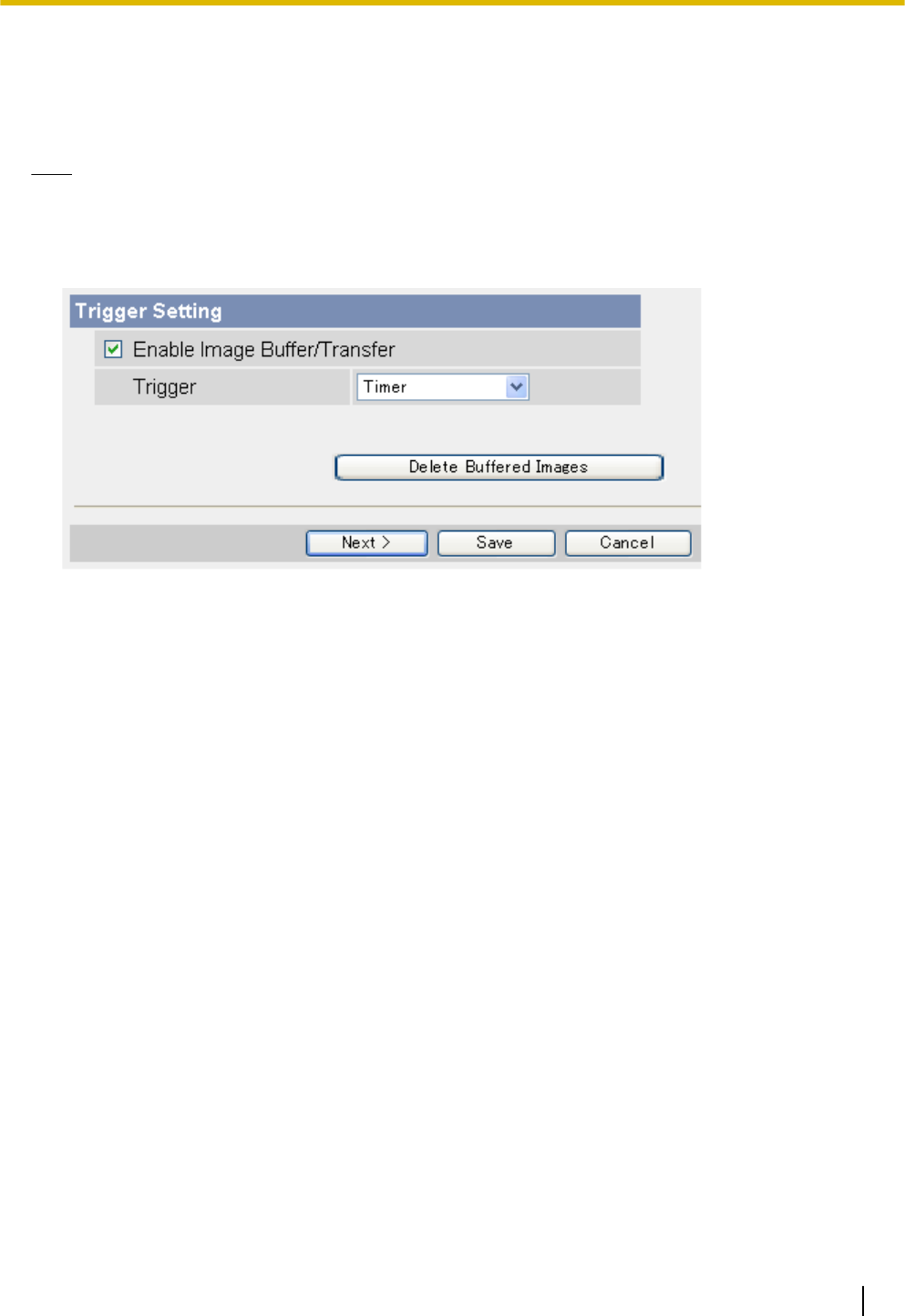
2.3 Disabling and Enabling a Trigger
After configuring an image buffering trigger, you can later disable the trigger to temporarily turn it off, and enable
it to turn it on again. While disabled, a trigger will not buffer images, transfer images, or send trigger notification.
Note
•When you enable or disable a trigger, all images for all triggers buffered in the memory are deleted.
1. Click the [Setup] tab.
2. On the left side of the screen under [Buffer/Transfer], click [Trigger].
3. Click a trigger number (1–5).
4. Uncheck [Enable Image Buffer/Transfer] to disable the trigger.
•To enable a trigger you disabled earlier, check [Enable Image Buffer/Transfer].
5. Click [Save].
•All images buffered are deleted when you click [Save].
Operating Instructions 59
2.3 Disabling and Enabling a Trigger

2.4 Configuring the Camera to Transfer Images
When configuring the camera’s timer, built-in sensor, external sensor, or detection triggers, you can set the
camera to transfer the captured images by FTP (see Page 61), E-mail (see Page 63), or HTTP (see
Page 66). Once images are successfully transferred, they are deleted.
60 Operating Instructions
2.4 Configuring the Camera to Transfer Images
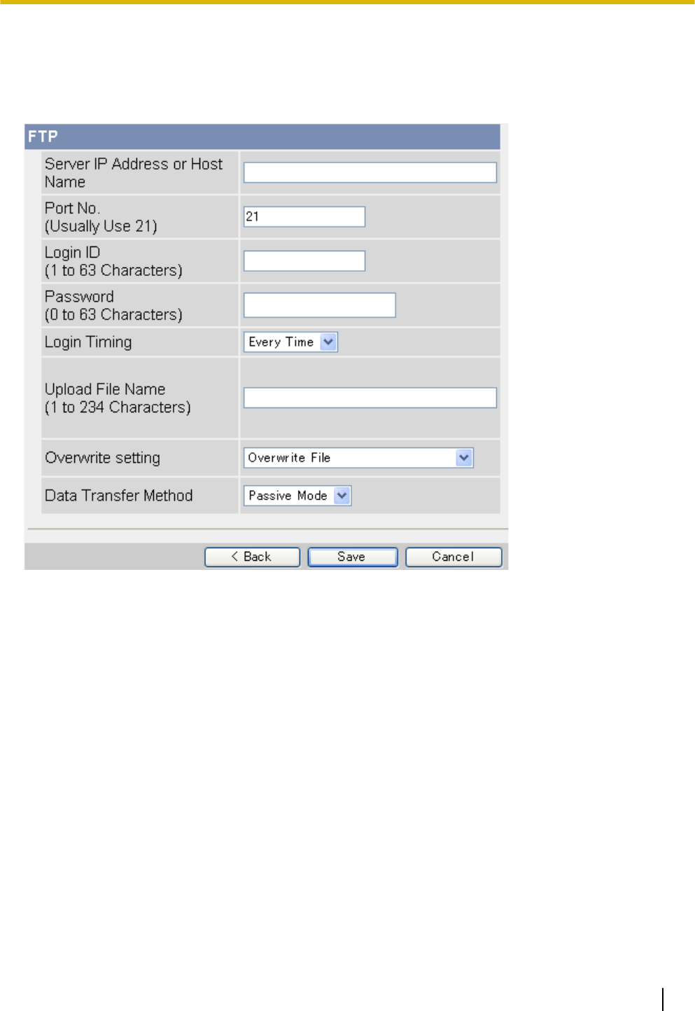
2.4.1 Transferring Images by FTP
The following screen is displayed if you select to transfer images by FTP while configuring a timer, built-in
sensor, external sensor, or detection trigger (see Page 51 or Page 54). Follow the procedure below to configure
the camera to transfer images to an FTP site. Ask the FTP server administrator for the appropriate settings.
1. Set the following parameters as desired.
a. Enter the IP address or host name*1 of the FTP server.
•An IPv6 address can be specified; note that the IPv6 address must be enclosed in brackets.
b. Enter the port number used by the server. (Port 21 is normally used for FTP.)
c. Enter the login ID*2 (user name) required to access the server (max. 63 characters).
d. Enter the password*2 required to access the server (max. 63 characters).
e. Select the desired setting for [Login Timing].
–[Every Time]: The camera logs in to the server every time it transfers an image to the server.
–[One Time]: The camera logs in to the server and stays connected for about 1 minute (unless a
new transfer begins before this time expires). This can reduce transfer time when several images
are transferred in a short time.
f. Enter the desired name*1 for transferred files (max. 234 characters). Transferred files will be saved
using this file name.
•You can specify existing directories on the server by entering “\” before the desired file name. For
example, if you enter “CameraImages\Image”, the camera will upload files to the
directory “CameraImages” and save the files using the name “Image”.
g. Select the desired setting for [Overwrite setting].
–[Overwrite File]: The file on the server is replaced by the file uploaded by the camera, i.e., only 1
file is saved on the server.
–[Save as New File with Time Stamp]: A time stamp is added to the end of the file name, allowing
multiple files to be saved on the server. For example, if you set the file name as “Image”, an
Operating Instructions 61
2.4.1 Transferring Images by FTP

uploaded file may be saved as “Image20090618173020500.jpg”.
The time stamp format is Year/Month/Date/24-hour time/Second/Millisecond.
Therefore, in this example, the file was captured on June 18, 2009, at 5:30 PM and 20 seconds
and 500 milliseconds. Note that if you configure the camera to adjust its time setting for Daylight
Saving Time/Summer Time (see Page 140), an “s” will be inserted between the date and time of
the time stamp.
h. Select the transfer method required to upload files to the server.
•Select [Passive Mode] normally. If files are not uploaded properly, change the setting to [Active
Mode].
2. Follow the procedure below based on the settings you made when configuring the trigger.
a. If you selected to not send notification when the camera is triggered, click [Save], then click [Go to
Trigger page].
b. If you selected to send notification when the camera is triggered, click [Next].
•The appropriate notification settings page is displayed.
–For E-mail notification, see Page 69.
–For HTTP notification, see Page 72.
*1 [Space], ["], ['], [&], [<], and [>] cannot be entered.
*2 ["] cannot be entered.
62 Operating Instructions
2.4.1 Transferring Images by FTP
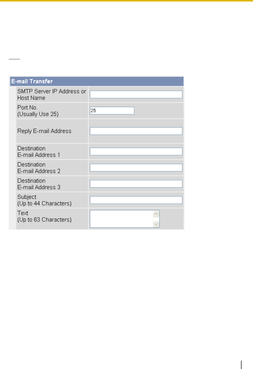
2.4.2 Transferring Images by E-mail
The following screen is displayed if you select to transfer images by E-mail while configuring a timer, built-in
sensor, external sensor, or detection trigger (see Page 51 or Page 54). Follow the procedure below to configure
the camera to send images to an E-mail address. Ask your Internet Service Provider (ISP) or network
administrator for the appropriate settings.
Note
•To prevent camera images from being sent to the wrong party, make sure you enter the desired
destination e-mail addresses correctly.
1. Set the following parameters as desired.
a. Under [E-mail Transfer], enter the IP address or the host name*1 of the SMTP server (outgoing mail
server).
•An IPv6 address can be specified; note that the IPv6 address must be enclosed in brackets.
•This feature cannot transfer images to web-based mail servers, such as Hotmail®.
b. Enter the port number used by the server. (Port 25 is normally used for sending E-mail.)
•Some ISPs require outgoing mail to be sent using port 587 or using SSL (SMTP over SSL) on port
465. Ask your ISP or network administrator for the appropriate setting.
c. Enter the reply E-mail address*2 that will be shown to the recipient as the sender of the E-mail.
•In an effort to reduce spam, many ISPs block E-mail sent through the SMTP server from an E-mail
address that is not associated with the SMTP server, therefore, we recommend entering the E-mail
assigned to you by your ISP.
d. Enter the destination E-mail address*2. Up to 3 addresses can be entered.
e. Enter the subject*2 that will be displayed in E-mail messages sent by the camera (max. 44 characters).
•The date and time (24-hour format) is automatically attached to the subject.
For example, if you enter “Camera” as the subject, an E-mail may be sent with the subject “Camera:
20090618173020500”.
The time stamp format is Year/Month/Date/24-hour time/Second/Millisecond.
Operating Instructions 63
2.4.2 Transferring Images by E-mail
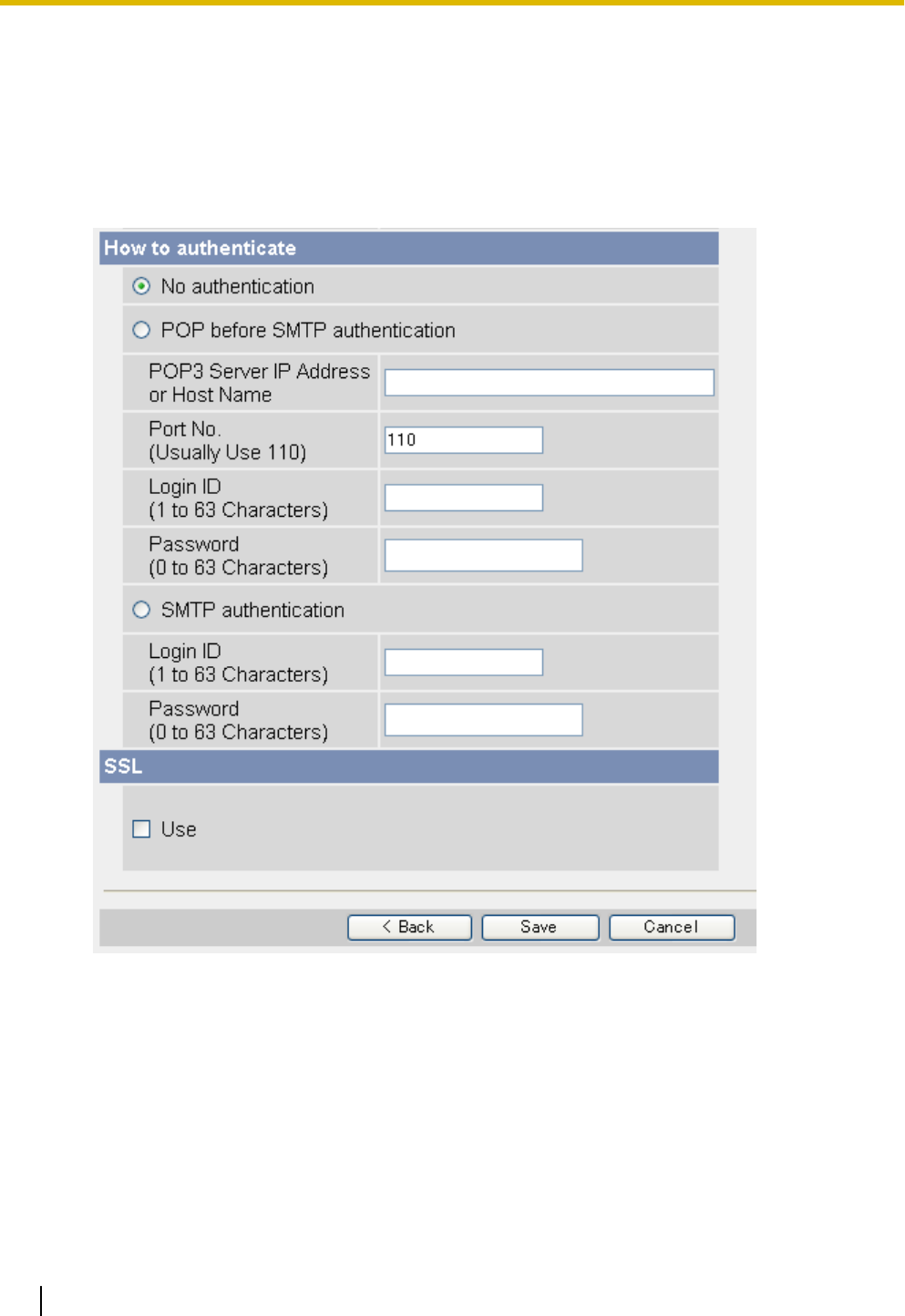
Therefore, in this example, the file was captured on June 18, 2009, at 5:30 PM and 20 seconds
and 500 milliseconds. Note that if you configure the camera to adjust its time setting for Daylight
Saving Time/Summer Time (see Page 140), an “s” will be inserted between the date and time of
the time stamp.
•The date and time is also used as the sent file name (i.e., 20090618173020500.jpg).
f. Enter the text*2 that will be displayed in the body of E-mail messages sent by the camera (max. 63
characters).
•Line breaks cannot be entered.
2. Under [How to authenticate], select the authentication method your ISP requires for sending E-mail, and
enter the appropriate settings if necessary.
–[No authentication]: Select this option if the outgoing E-mail server does not require authentication
when sending E-mail messages.
–[POP before SMTP authentication]: Select this option if the outgoing E-mail server requires POP before
SMTP authentication when sending E-mail messages. The following settings are also necessary. Enter
the settings as you would for receiving E-mail.
a. Enter the IP address or the host name*1 of the POP3 server (incoming mail server).
•An IPv6 address can be specified; note that the IPv6 address must be enclosed in brackets.
b. Enter the port number used by the server. (Port 110 is normally used for POP3.)
c. Enter the login ID*2 (user name) required to access the server (max. 63 characters).
d. Enter the password*2 required to access the server (max. 63 characters).
64 Operating Instructions
2.4.2 Transferring Images by E-mail

–[SMTP authentication]: Select this option if the outgoing E-mail server requires SMTP authentication
when sending E-mail messages. The following settings are also necessary. Enter the settings as you
would for sending E-mail.
a. Enter the login ID*2 (user name) required to access the server (max. 63 characters).
b. Enter the password*2 required to access the server (max. 63 characters).
•The camera supports LOGIN, PLAIN, and CRAM-MD5 authentication.
3. Under [SSL], select [Use] if you want to use SSL encryption when sending E-mail.
•When [Use] is selected, the port number under [E-mail Transfer] may need to be set to 465. Ask your
ISP or network administrator for the appropriate settings.
•SSL supports SMTP over SSL. STARTTLS is not supported.
4. Follow the procedure below based on the settings you made when configuring the trigger.
a. If you selected to not send notification when the camera is triggered, click [Save], then click [Go to
Trigger page].
b. If you selected to send notification when the camera is triggered, click [Next].
•The appropriate notification settings page is displayed.
–For E-mail notification, see Page 69.
–For HTTP notification, see Page 72.
*1 [Space], ["], ['], [&], [<], and [>] cannot be entered.
*2 ["] cannot be entered.
Operating Instructions 65
2.4.2 Transferring Images by E-mail
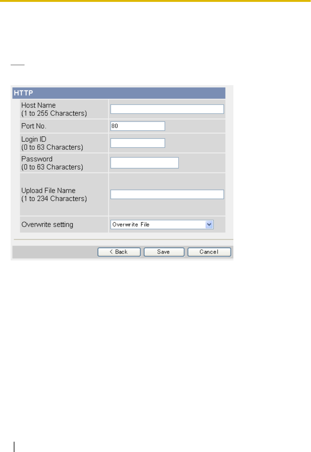
2.4.3 Transferring Images by HTTP
The following screen is displayed if you select to transfer images by HTTP while configuring a timer, built-in
sensor, external sensor, or detection trigger (see Page 51 or Page 54). Follow the procedure below to configure
the camera to transfer images to an HTTP site. Ask the HTTP server administrator for the appropriate settings.
Note
•If your camera’s network uses a proxy server, the appropriate proxy server settings must be made on
the [Network (IPv4)] page in order for images to be transferred by HTTP (see Page 118).
1. Set the following parameters as desired.
a. Enter the URL*1 of the HTTP server (max. 255 characters).
•An IPv6 address can be specified; note that the IPv6 address must be enclosed in brackets.
b. Enter the port number used by the server. (Port 80 is normally used for HTTP.)
c. Enter the login ID*2 (user name) required to access the server (max. 63 characters).
d. Enter the password*2 required to access the server (max. 63 characters).
e. Enter the desired name*2 for transferred files (max. 234 characters). Transferred files will be saved
using this file name.
•You can specify existing directories on the server by entering “\” before the desired file name. For
example, if you enter “CameraImages\Image”, the camera will upload files to the
directory “CameraImages” and save the files using the name “Image”.
f. Select the desired setting for [Overwrite setting].
–[Overwrite File]: The file on the server is replaced by the file uploaded by the camera, i.e., only 1
file is saved on the server.
–[Save as New File with Time Stamp]: A time stamp is added to the end of the file name, allowing
multiple files to be saved on the server. For example, if you set the file name as “Image”, an
uploaded file may be saved as “Image20090618173020500.jpg”.
The time stamp format is Year/Month/Date/24-hour time/Second/Millisecond.
Therefore, in this example, the file was captured on June 18, 2009, at 5:30 PM and 20 seconds
and 500 milliseconds. Note that if you configure the camera to adjust its time setting for Daylight
66 Operating Instructions
2.4.3 Transferring Images by HTTP

Saving Time/Summer Time (see Page 140), an “s” will be inserted between the date and time of
the time stamp.
2. Follow the procedure below based on the settings you made when configuring the trigger.
a. If you selected to not send notification when the camera is triggered, click [Save], then click [Go to
Trigger page].
b. If you selected to send notification when the camera is triggered, click [Next].
•The appropriate notification settings page is displayed.
–For E-mail notification, see Page 69.
–For HTTP notification, see Page 72.
*1 [Space], ["], ['], [&], [<], and [>] cannot be entered.
*2 ["] cannot be entered.
Operating Instructions 67
2.4.3 Transferring Images by HTTP

2.5 Configuring the Camera to Send Trigger
Notifications
When configuring the camera to buffer or transfer images by built-in sensor or external sensor, or by the
detection feature, you can configure the camera to send notifications by E-mail (see Page 69) or HTTP (see
Page 72) when the camera is triggered.
Note
•Notifications cannot be sent when buffering or transferring images by timer.
•You can also send a log of trigger notifications once a day (see Page 87).
68 Operating Instructions
2.5 Configuring the Camera to Send Trigger Notifications
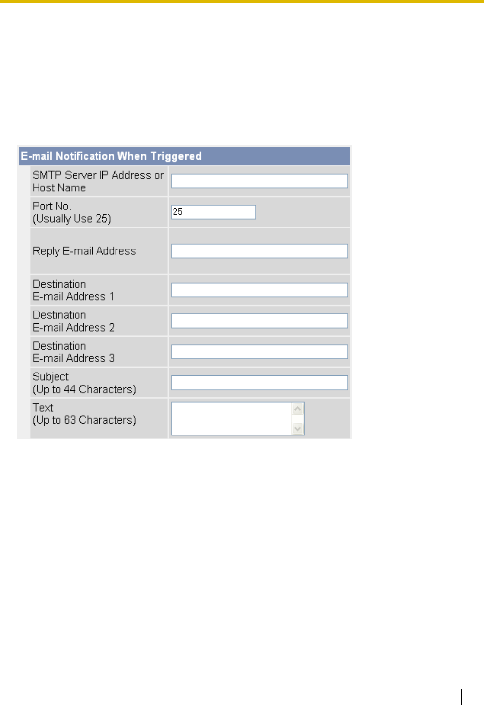
2.5.1 Sending Trigger Notifications by E-mail
The following screen is displayed while configuring the camera to buffer or transfer images by built-in sensor
or external sensor, or by detection (see Page 54) if you select [Send E-mail Notification]. Follow the procedure
below to send trigger notifications by E-mail. Ask your Internet Service Provider (ISP) or network administrator
for the appropriate settings.
Note
•To prevent trigger notifications from being sent to the wrong party, make sure you enter the desired
destination e-mail addresses correctly.
1. Set the following parameters as desired.
a. Under [E-mail Notification When Triggered], enter the IP address or the host name*1 of the SMTP server
(outgoing mail server).
•An IPv6 address can be specified; note that the IPv6 address must be enclosed in brackets.
•This feature cannot transfer images to web-based mail servers, such as Hotmail.
b. Enter the port number used by the server. (Port 25 is normally used for sending E-mail.)
•Some ISPs require outgoing mail to be sent using port 587 or using SSL (SMTP over SSL) on port
465. Ask your ISP or network administrator for the appropriate setting.
c. Enter the reply E-mail address*2 that will be shown to the recipient as the sender of the E-mail.
•In an effort to reduce spam, many ISPs block E-mail sent through the SMTP server from an E-mail
address that is not associated with the SMTP server, therefore, we recommend entering the E-mail
address assigned to you by your ISP.
d. Enter the destination E-mail address*2. Up to 3 addresses can be entered.
e. Enter the subject*2 that will be displayed in E-mail messages sent by the camera (max. 44 characters).
•The date and time (24-hour format) is automatically attached to the subject.
For example, if you enter “CameraNotification” as the subject, an E-mail may be sent with the
subject “CameraNotification:20090618173020500”.
The time stamp format is Year/Month/Date/24-hour time/Second/Millisecond.
Operating Instructions 69
2.5.1 Sending Trigger Notifications by E-mail
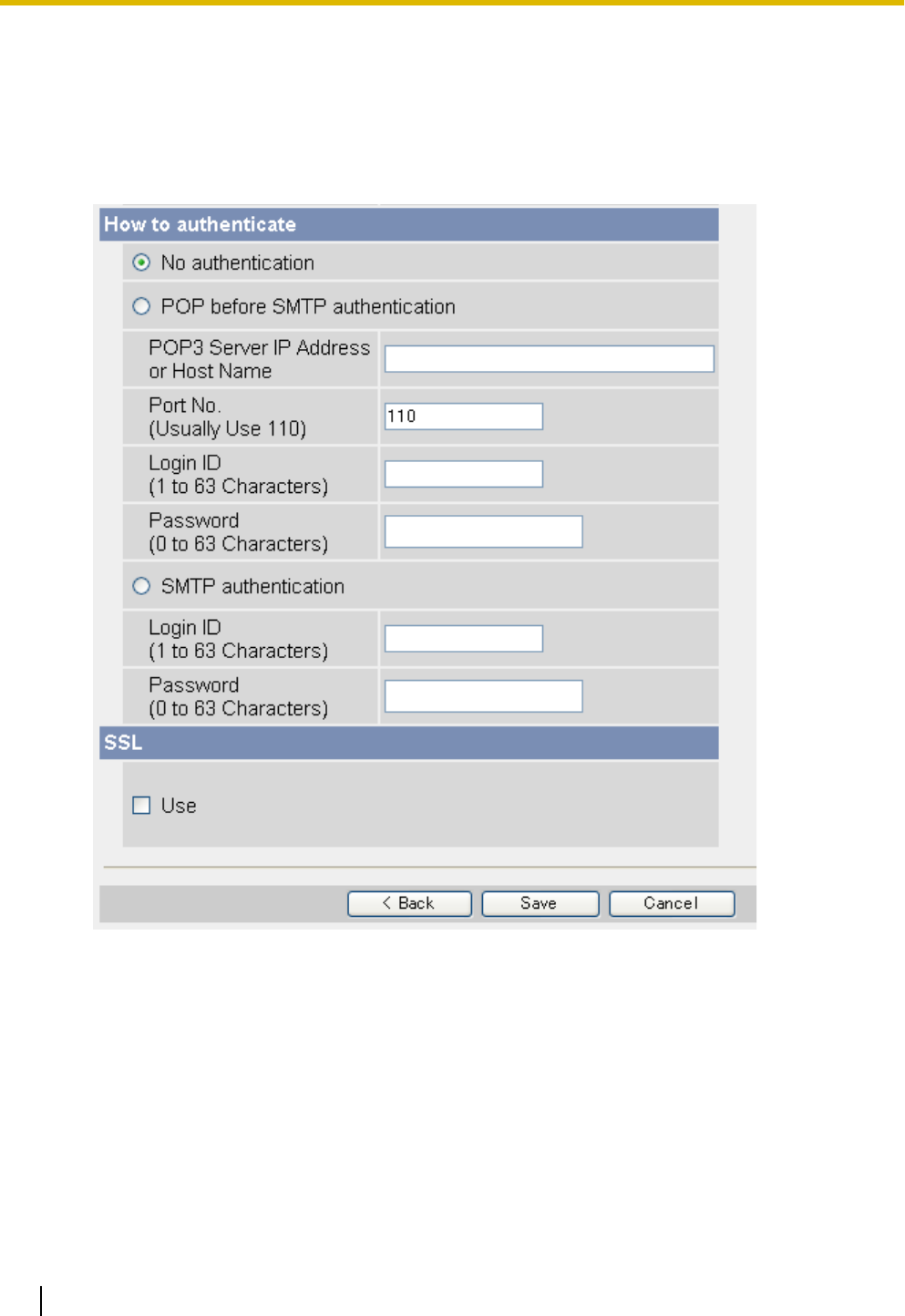
Therefore, in this example, the camera was triggered on June 18, 2009, at 5:30 PM and 20 seconds
and 500 milliseconds. Note that if you configure the camera to adjust its time setting for Daylight
Saving Time/Summer Time (see Page 140), an “s” will be inserted between the date and time of
the time stamp.
f. Enter the text*2 that will be displayed in the body of E-mail messages sent by the camera (max. 63
characters).
•Line breaks cannot be entered.
2. Under [How to authenticate], select the authentication method your ISP requires for sending E-mail, and
enter the appropriate settings if necessary.
–[No authentication]: Select this option if the outgoing E-mail server does not require authentication
when sending E-mail messages.
–[POP before SMTP authentication]: Select this option if the outgoing E-mail server requires POP before
SMTP authentication when sending E-mail messages. The following settings are also necessary. Enter
the settings as you would for receiving E-mail.
a. Enter the IP address or the host name*1 of the POP3 server (incoming mail server).
•An IPv6 address can be specified; note that the IPv6 address must be enclosed in brackets.
b. Enter the port number used by the server. (Port 110 is normally used for POP3.)
c. Enter the login ID*2 (user name) required to access the server (max. 63 characters).
d. Enter the password*2 required to access the server (max. 63 characters).
70 Operating Instructions
2.5.1 Sending Trigger Notifications by E-mail

–[SMTP authentication]: Select this option if the outgoing E-mail server requires SMTP authentication
when sending E-mail messages. The following settings are also necessary. Enter the settings as you
would for sending E-mail.
a. Enter the login ID*2 (user name) required to access the server (max. 63 characters).
b. Enter the password*2 required to access the server (max. 63 characters).
•The camera supports LOGIN, PLAIN, and CRAM-MD5 authentication.
3. Under [SSL], select [Use] if you want to use SSL encryption when sending E-mail.
•When [Use] is selected, the port number under [E-mail Transfer] may need to be set to 465. Ask your
ISP or network administrator for the appropriate settings.
•SSL supports SMTP over SSL. STARTTLS is not supported.
4. Click [Save], then click [Go to Trigger page].
*1 [Space], ["], ['], [&], [<], and [>] cannot be entered.
*2 ["] cannot be entered.
Operating Instructions 71
2.5.1 Sending Trigger Notifications by E-mail
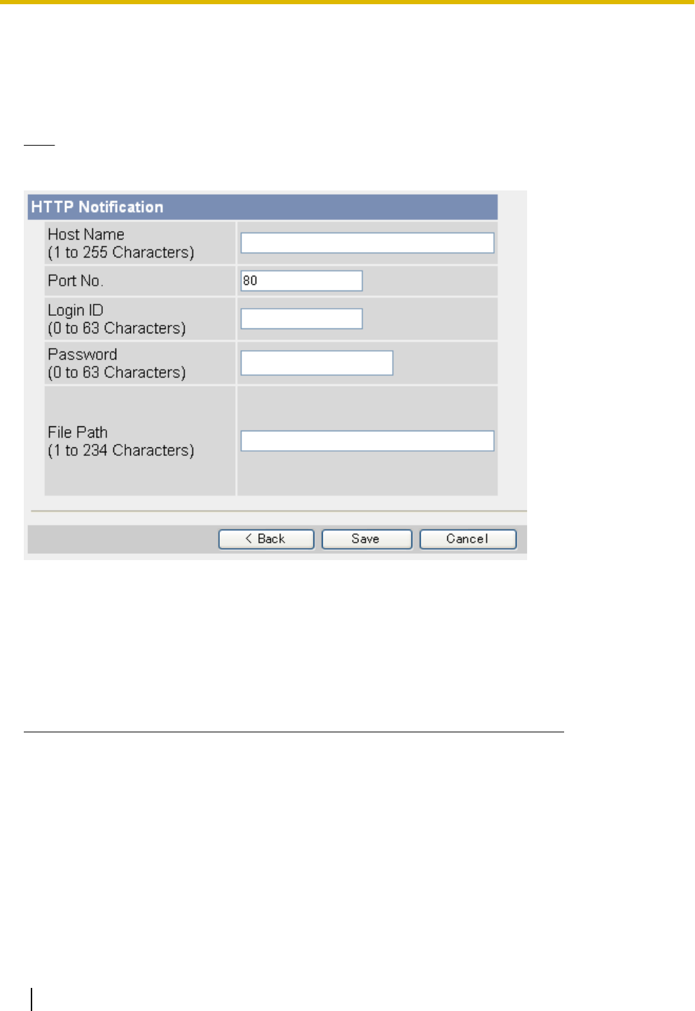
2.5.2 Sending Trigger Notifications by HTTP
The following screen is displayed while configuring the camera to buffer or transfer images by built-in sensor
or external sensor, or by detection (see Page 54) if you select [Send HTTP Notification]. Follow the procedure
below to send trigger notifications by HTTP.
Note
•If your camera’s network uses a proxy server, the appropriate proxy server settings must be made on
the [Network (IPv4)] page in order for images to be transferred by HTTP (see Page 118).
1. Set the following parameters as desired.
a. Enter the URL*1 of the HTTP server (max. 255 characters).
•An IPv6 address can be specified; note that the IPv6 address must be enclosed in brackets.
b. Enter the port number used by the server. (Port 80 is normally used for HTTP.)
c. Enter the login ID*2 (user name) required to access the server (max. 63 characters).
d. Enter the password*2 required to access the server (max. 63 characters).
e. Enter the path*2 to the desired CGI file on the server.
2. Click [Save], then click [Go to Trigger page].
*1 [Space], ["], ['], [&], [<], and [>] cannot be entered.
*2 ["] cannot be entered.
72 Operating Instructions
2.5.2 Sending Trigger Notifications by HTTP

2.6 Viewing Buffered Images
If you have configured the camera to buffer images (see Page 51 or Page 54), you can access the camera
and view the buffered images.
Note
•If you have configured the camera to transfer images by FTP, E-mail, or HTTP, images are deleted
once they have been successfully transferred and you cannot view the images using the procedure
described in this section.
•When buffering MPEG-4 videos, the videos cannot be viewed until buffering has ended. Buffering ends
when the memory is full (up to 1 minute when buffering images to the internal memory).
•Buffering ends when the buffered file size reaches 20 MB. When the 20 MB limit is reached, a new file
is created. Note that it may take 20 minutes or more for a 20 MB file to be buffered.
1. Click the [Buffered Image] tab.
•The oldest buffered image for triggers 1–5 are displayed.
•If an image was buffered in MPEG-4 format, a black screen is displayed.
•If a trigger is disabled, or if the trigger has not yet buffered images, a gray screen is displayed.
•Date and time overlays, status overlays, and text overlays may be displayed on buffered images
according to the [Overlay Setting] (see Page 159). See Page 11 for an example of a camera image
overlays.
1. Timer 2. Sensor 3. Motion Detection
4.Sound Detection 5. Alarm1
2. Click the trigger title corresponding to buffered images you want to view.
Operating Instructions 73
2.6 Viewing Buffered Images
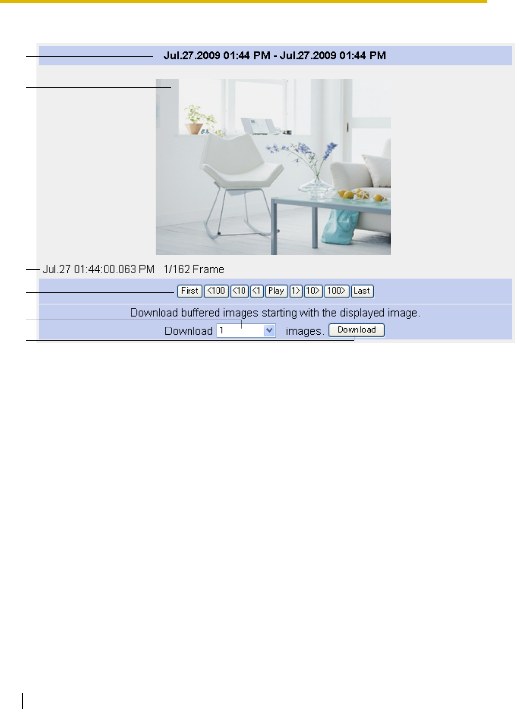
Viewing and downloading buffered JPEG images (videos and still images)
A
B
C
D
E
F
A. Start and end date and time when the image was buffered
B. Camera image
C. Date and time when the displayed image was buffered, current image number, and total number of images
buffered
D. Playback controls (explained below)
E. Click to select how many images will be downloaded when [Download] is clicked
F. Click to download the selected number of images
Playing images
[Play]: All buffered images are played back in sequence beginning with the current image
[First] or [Last]: The first or last image is displayed
[<100], [<10], [<1]: “Rewinds” by the corresponding number of frames
[100>], [10>], [1>]: “Fast-forwards” by the corresponding number of frames
Note
•Date, time and image number are not displayed during playback.
•The ActiveX zoom feature (see Page 30) can be used during playback.
•Screen content varies by model number.
Downloading images
Select the number of frames you want to download, click [Download], and specify a location on your PC to
save the images. The selected number of frames will be downloaded, beginning with the frame currently
displayed. You can save every frame beginning with the current frame to the last frame by selecting
[remaining]. Images are saved in PNC format. You can view them conveniently using the Network Camera SD
Viewer software. This software can be found on the included CD-ROM, and can be installed by following the
74 Operating Instructions
2.6 Viewing Buffered Images
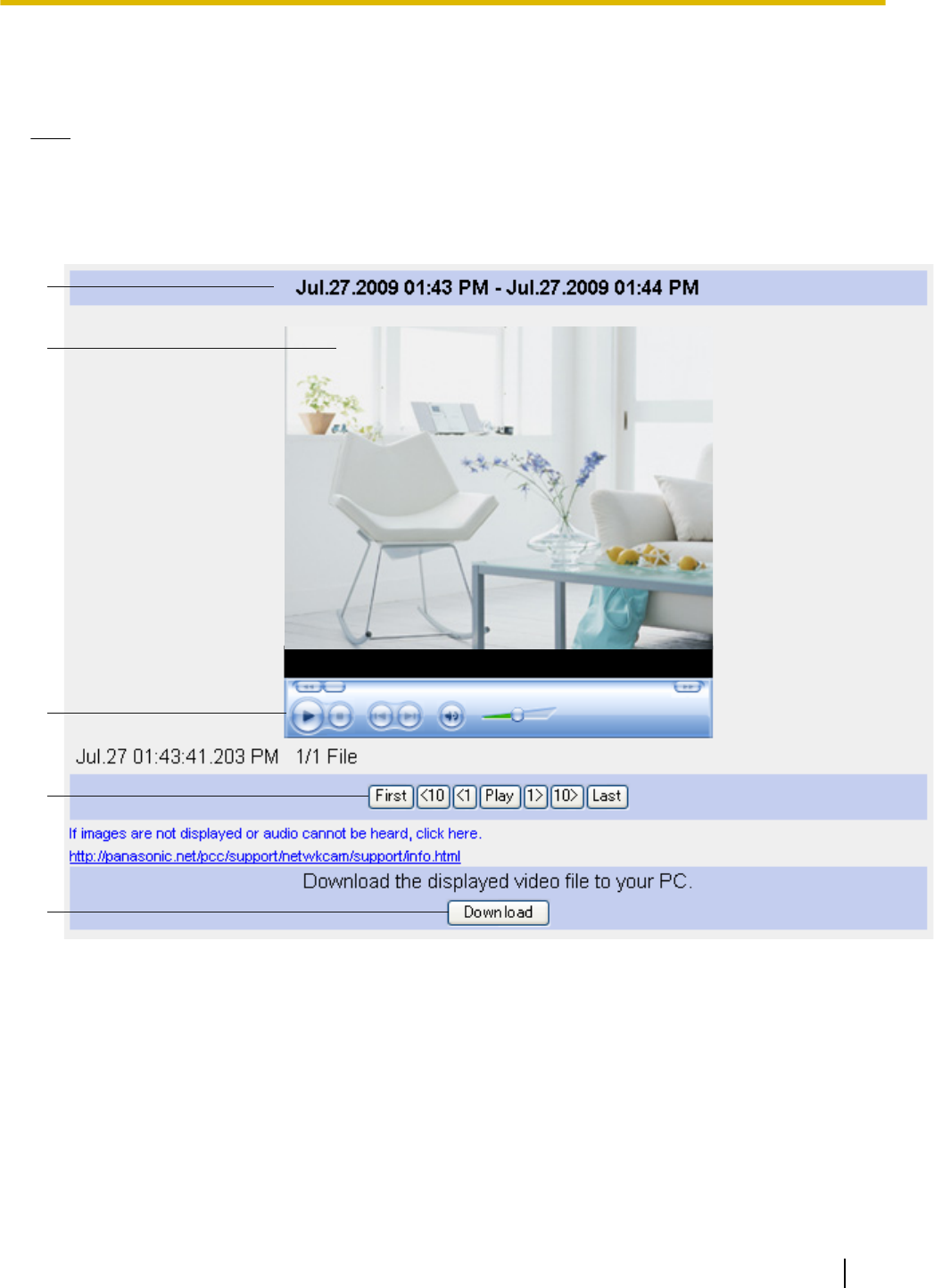
instructions in the “Read Me” file (CD-ROM Drive:\NCV\SDVIEWER_README.txt). You can also download
this software from the Panasonic Network Camera website (http://panasonic.net/pcc/support/netwkcam/).
You can also download a still image by right-clicking in the image area and selecting [Save Picture As...].
Note
•The number of simultaneous viewing sessions is limited. When the maximum number of accesses has
been exceeded (refer to the tables in Page 48), additional users will see a gray screen.
Viewing and downloading buffered MPEG-4 videos
A
B
C
D
E
A. Start and end date and time when the image was buffered
B. Camera image
C. Windows Media® Player controls (refer to the Windows Media Player help file for details)
D. Playback controls (explained below)
E. Download button
Playing videos
[Play]: All buffered MPEG-4 files are played back in sequence beginning with the current file
[First] or [Last]: The first or last file is played back
[<10], [<1]: “Rewinds” by the corresponding number of files
[10>], [1>]: “Fast-forwards” by the corresponding number of files
Operating Instructions 75
2.6 Viewing Buffered Images

Note
•A video file cannot be played back while it is still being recorded.
•The G.726 audio codec must be downloaded and installed on your PC in order to view buffered videos.
Click the link below [If images are not displayed or audio cannot be heard, click here.] to view
information and download the codec.
•Date, time and file number are not displayed during playback.
•If you click [Play] to play all MPEG-4 files, playback may stop in the middle of a file when using Windows
Vista. In this case, click the play button in Windows Media Player to resume playback.
•Screen content varies by model number.
Downloading videos
Click [Download], and specify a location on your PC to save the file. The current video file will be saved on
your PC in ASF (Advanced Streaming Format) format, which is a file format used by Windows Media. You can
view video files later using Windows Media Player.
Note
•The maximum length of videos that can be buffered in the memory, as well as the total number of
videos that can be buffered in the memory, varies on image resolution, MPEG-4 frame rate and bit rate
settings, and the content of the videos being buffered.
•See the Panasonic Network Camera support site (http://panasonic.net/pcc/support/netwkcam/) for
more information about viewing or downloading buffered MPEG-4 videos.
76 Operating Instructions
2.6 Viewing Buffered Images
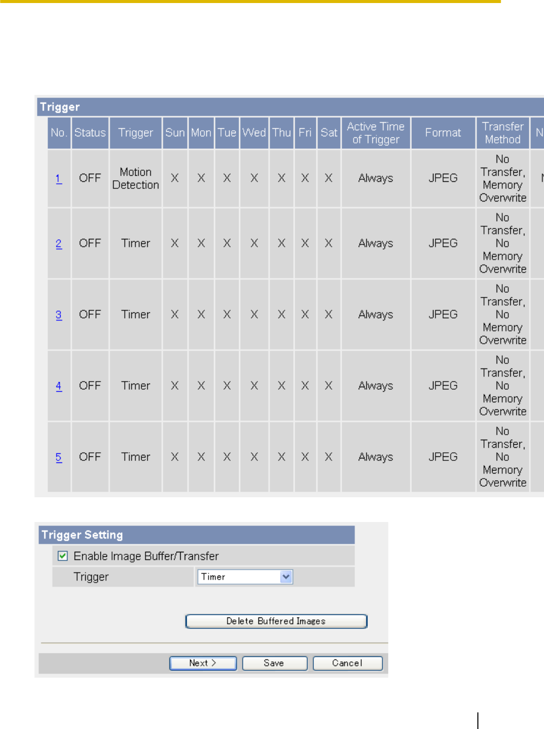
2.7 Deleting Buffered Images Manually
You can delete all images in the memory buffered by a specific trigger.
1. Click the [Setup] tab.
2. On the left side of the screen under [Buffer/Transfer], click [Trigger].
3. Click a trigger number (1–5).
Operating Instructions 77
2.7 Deleting Buffered Images Manually

4. Click [Delete Buffered Images].
5. Click [OK].
Note
•The following operations also delete all images buffered in the internal memory.
–Turning off the camera.
–Saving the Date and Time page.
–Restarting, updating firmware or resetting the camera to factory default.
–Disabling or enabling a trigger.
–Restoring settings from a configuration file.
78 Operating Instructions
2.7 Deleting Buffered Images Manually

2.8 Understanding How the Camera Manages
Buffered Images
When images are buffered in the camera’s internal memory
The camera’s internal memory is divided between the number of triggers that are configured. For example, if
5 triggers are set, each trigger can use 1/5 of the camera’s internal memory, and if 3 triggers are set, each
trigger can use 1/3 of the camera’s internal memory, etc. See Page 207 for information about the camera’s
internal memory capacity.
For example, when buffering JPEG images at 320 ´ 240 resolution and standard quality:
Number of triggers 1 2 3 4 5
Maximum number of JPEG images that can be buffered
by each trigger (approximate) 1160 580 385 290 230
When you change settings for a trigger, all images buffered in the internal memory for the selected trigger are
deleted. Additionally, images buffered for other triggers may also be deleted. When configuring a trigger to
buffer or transfer images, it is important to understand how the camera manages buffered images.
All images for the selected trigger are deleted when:
–You change the settings for a trigger (image buffer frequency, transfer method, transfer settings, etc.)
–You click [Delete Buffered Images] on the trigger page
All images for all triggers are deleted when:
–You disable or enable a trigger (see Page 59)
–You restart the camera (see Page 180)
–You update the camera’s firmware (see Page 181 and Page 203)
–You reset the camera to its default settings (see Page 184)
–You change the date and time setting (see Page 140)
–You restore settings from a configuration file (see Page 183)
When selecting [No Transfer, Memory Overwrite] for buffering JPEG images using sensor,
alarm, or detection triggers
If you want to configure the camera to buffer pre-trigger and post-trigger images, please note the following
recommended settings when selecting [No Transfer, Memory Overwrite] for buffering JPEG images using
sensor, alarm, or detection triggers.
When buffering JPEG images at 320 ´ 240 resolution and standard quality:
Number of triggers 1 2 3 4 5
Maximum number of JPEG images that can be buffered
by each trigger (approximate) (“A”) 1160 580 385 290 230
Recommended maximum number of pre-trigger
images (“B”) 385 190 125 95 75
Recommended maximum number of post-trigger
images (when the number of pre-trigger images shown
above is set) (“C”)
390 200 135 100 80
Approximate number of images buffered when using
the above settings (“D”) 775 390 260 195 155
Note
•As a general guideline, the recommended maximum number of pre-trigger images is about 1/3 of the
maximum number of images that can be buffered by the trigger.
(“B” equals or is less than “A”´1/3, as shown above).
Operating Instructions 79
2.8 Understanding How the Camera Manages Buffered Images

•As a general guideline, the number of post-trigger images should not exceed the total number of images
that can be buffered by the trigger minus 2 times the number of pre-trigger images.
(“C” equals or is less than “A”-(2´“B”), as shown above).
•Note that when using the above settings, the actual number of images buffered (“D”) is less than the
maximum number of images that can be buffered by the trigger (“A”).
•If the value set for post-trigger images is set too high, pre-trigger images may be overwritten.
•If the value set for pre-trigger images is set too high, images may not be buffered as expected.
80 Operating Instructions
2.8 Understanding How the Camera Manages Buffered Images
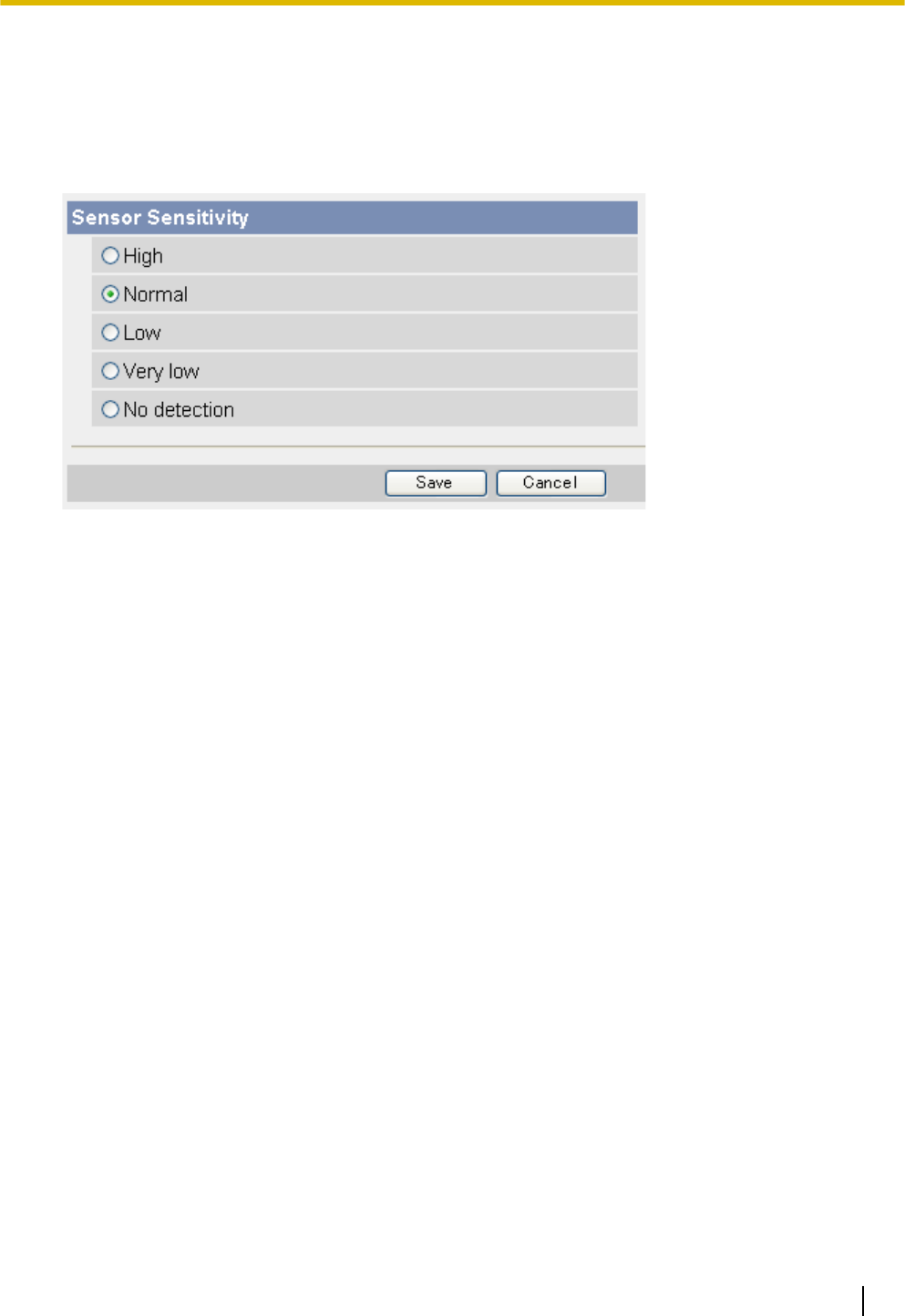
2.9 Adjusting Sensor Sensitivity
If using the camera’s built-in sensor to buffer or transfer camera images, you may want to adjust the sensor’s
sensitivity for optimal results.
1. Click the [Setup] tab.
2. On the left side of the screen under [Buffer/Transfer], click [Sensor Sensitivity].
3. Select the desired setting.
–[High]: The sensor is more sensitive to heat variations.
–[Normal]: The sensor is moderately sensitive to heat variations (default).
–[Low]: The sensor is less sensitive to heat variations.
–[Very Low]: The sensor is further less sensitive to heat variations.
–[No detection]: The sensor does not detect heat variations.
4. Click [Save].
Operating Instructions 81
2.9 Adjusting Sensor Sensitivity
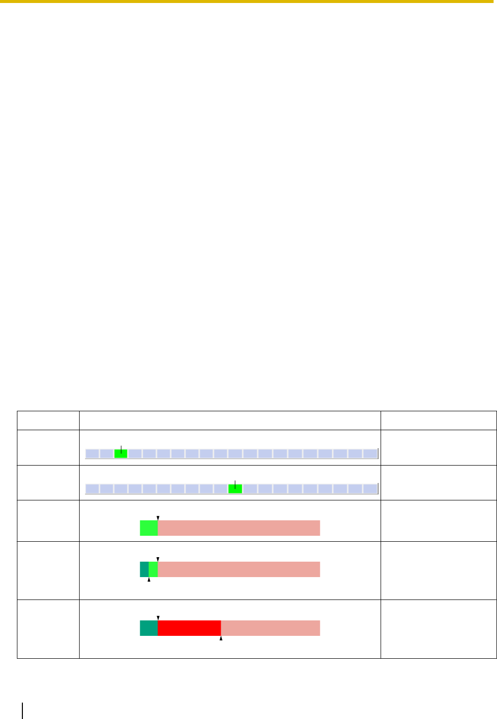
2.10 Adjusting Motion Detection Sensitivity
If using the motion detection feature to buffer or transfer camera images, you may want to adjust the motion
detection sensitivity for optimal results.
1. Click the [Setup] tab.
2. On the left side of the screen under [Buffer/Transfer], click [Motion Detection].
3. Observe the [Preview] area to confirm how the current settings detect motion.
•Any changes you make on this page will not be reflected in the [Preview] area until you click [Save].
•You can click on the image in the [Preview] area to use the click to center feature and aim the lens in
the desired direction when confirming the current sensitivity settings.
4. If necessary, adjust the detection threshold by clicking the appropriate block.
5. If necessary, adjust the motion sensitivity by clicking the appropriate block.
6. Click [Save], and then click [Go to Motion Detection page].
7. Observe the [Preview] area to confirm how the new settings detect motion, and repeat from step 4 if
necessary.
Understanding [Threshold] and [Sensitivity]
Motion detection threshold and sensitivity can be adjusted. Understanding how threshold and sensitivity
interact will help you adjust the motion detection feature to suit your needs.
[Threshold]: Determines at what point the motion detection feature is triggered. A lower threshold means less
motion is needed to trigger the motion detection feature. A higher threshold means more motion is needed to
trigger the motion detection feature. Threshold is indicated in the [Preview] area by the light green area.
[Sensitivity]: Determines how easily the camera detects motion. Lower sensitivity means the camera is less
likely to detect motion. Higher sensitivity means the camera is more likely to detect motion. Motion is indicated
in the [Preview] area in dark green when it has not exceeded the detection threshold, and is indicated in dark
red when it has exceeded the detection threshold.
[Preview]: Refer to this area to see how the current settings (effective after clicking [Save]) detect motion.
The following examples show how [Threshold] and [Sensitivity] are represented in the [Preview] area.
Example 1
Parameter Display Meaning
[Threshold]
A
Low threshold (A)
[Sensitivity]
B
Moderate sensitivity (B)
[Preview]
A
Low threshold (A), no
motion is detected
[Preview]
C
A
Low threshold (A), low
motion (C), motion
detection is not
triggered
[Preview]
D
A
Low threshold (A),
moderate (D), motion
detection is triggered
82 Operating Instructions
2.10 Adjusting Motion Detection Sensitivity
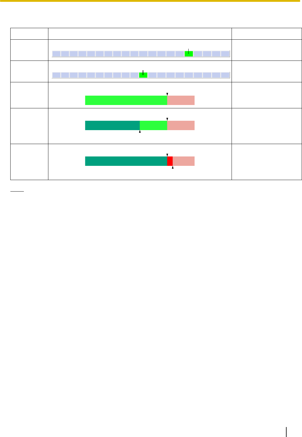
Example 2
Parameter Display Meaning
[Threshold]
A
High threshold (A)
[Sensitivity]
B
Moderate sensitivity (B)
[Preview]
A
High threshold (A), no
motion is detected
[Preview]
A
C
High threshold (A),
moderate motion (C),
motion detection is
not triggered
[Preview]
A
D
High threshold (A), high
motion (D), motion
detection is triggered
Note
•Motion is detected by changes in the outline of objects and changes in object brightness, however, in
some cases the camera may detect rapid brightness changes by artificial light sources (such as
fluorescent lights) as motion.
•The camera’s motion detection feature detects motion differently than the Network Camera Recorder
software (sold separately).
•Motion may not be detected as desired if the object’s color is similar to the color of the background.
•The motion detection feature is disabled when panning and tilting the camera lens, i.e., moving the
camera lens will not trigger the motion detection feature.
•Motion detection can vary by the object, image resolution, or image quality. Refer to the [Preview] area
to see how the current settings detect motion.
Operating Instructions 83
2.10 Adjusting Motion Detection Sensitivity
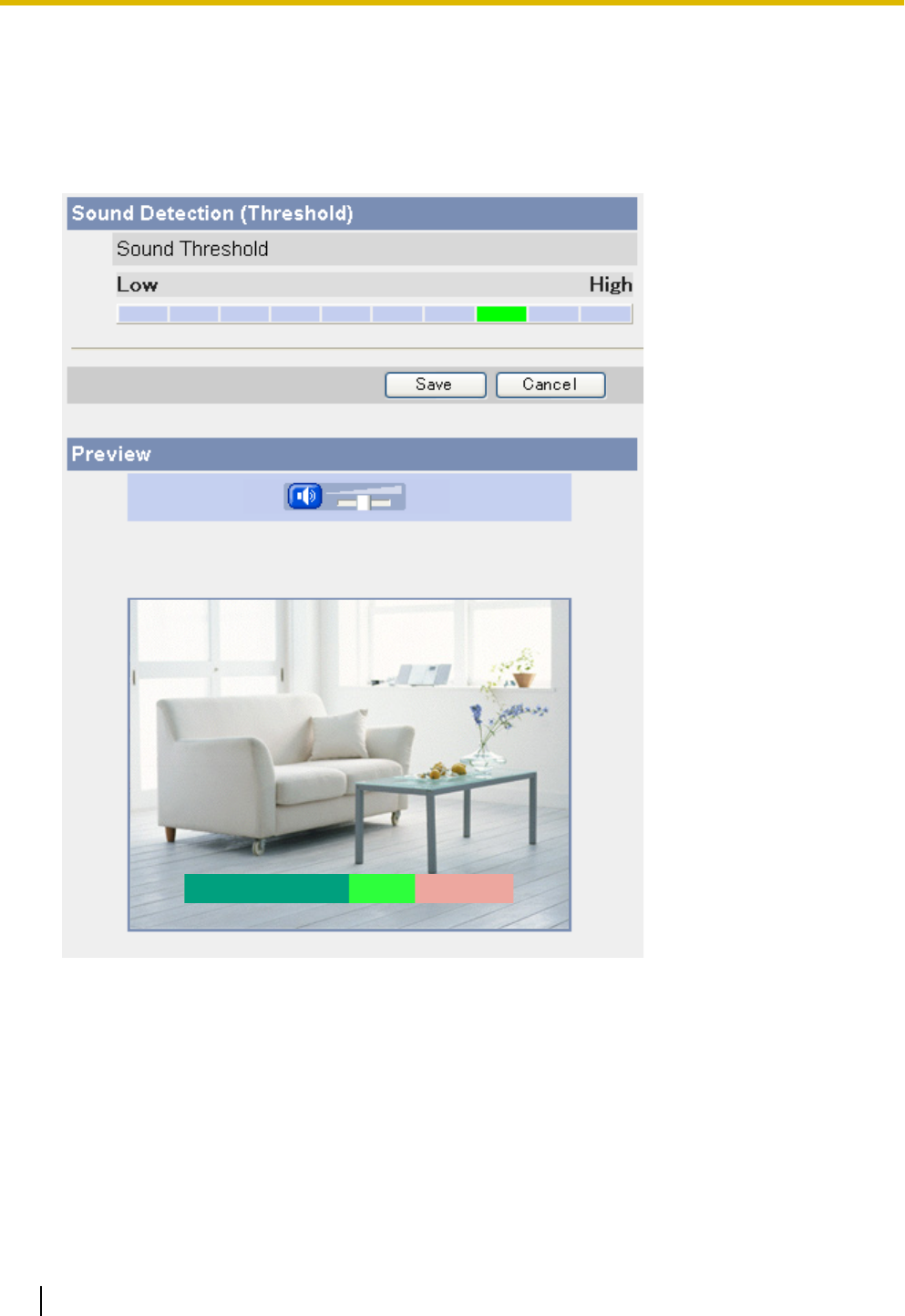
2.11 Adjusting Sound Detection Sensitivity
If using the sound detection feature to buffer or transfer camera images, you may want to adjust the threshold
for sound detection in order to achieve the desired results.
1. Click the [Setup] tab.
2. On the left side of the screen under [Buffer/Transfer], click [Sound Detection].
3. Observe the [Preview] area to confirm how the current settings trigger sound detection.
•When the sound level indicator is green, the camera’s microphone is picking up sound but the volume
is not high enough to trigger the sound detection feature. When the sound level is red, the sound
detection feature is triggered.
•Any changes you make on this page will not be reflected in the [Preview] area until you click [Save].
4. If necessary, adjust the detection threshold by clicking the appropriate block.
5. Click [Save], and then click [Go to Sound Detection page].
6. Observe the [Preview] area to confirm how the new settings trigger sound detection, and repeat from step
4 if necessary.
84 Operating Instructions
2.11 Adjusting Sound Detection Sensitivity
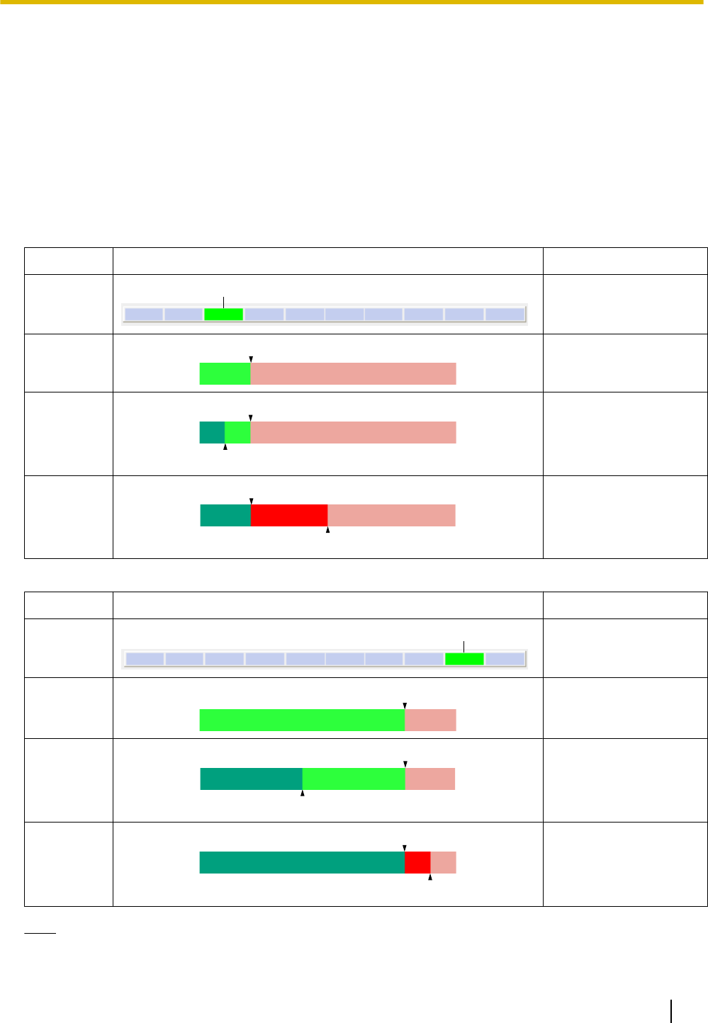
Understanding [Threshold]
Sound detection threshold can be adjusted. Understanding how threshold will help you adjust the sound
detection feature to suit your needs.
[Threshold]: Determines at what point the sound detection feature is triggered. A lower threshold means less
sound is needed to trigger the sound detection feature, i.e., sound detection is triggered at lower volumes. A
higher threshold means more sound is needed to trigger the sound detection feature, i.e., sound detection is
only triggered at higher volumes. Note that the [Camera Microphone Sensitivity] setting on the [Audio] page
controls microphone sensitivity (Page 144); if the microphone sensitivity is adjusted, the [Threshold] setting
for the sound detection feature may also need to be adjusted to achieve the desired results.
[Preview]: Refer to this area to see how the current settings (effective after clicking [Save]) detect sound.
Example 1
Parameter Display Meaning
[Threshold]
A
Low threshold (A)
[Preview]
A
Low threshold (A), no
sound is detected
[Preview]
B
A
Low threshold (A), low
volume (B), sound
detection is not
triggered
[Preview]
C
A
Low threshold (A),
moderate volume (C),
sound detection is
triggered
Example 2
Parameter Display Meaning
[Threshold]
A
High threshold (A)
[Preview]
A
High threshold (A), no
sound is detected
[Preview]
A
B
High threshold (A),
moderate volume (B),
sound detection is not
triggered
[Preview]
A
C
High threshold (A), high
volume (C), sound
detection is triggered
Note
•The audio and video may not be in sync in the [Preview] area.
Operating Instructions 85
2.11 Adjusting Sound Detection Sensitivity

•The sound detection feature cannot detect sound when the [Input] setting is set to [Disable] on the
[Audio] page (see Page 144).
•The [Camera Microphone Sensitivity] setting on the [Audio] page affects sound detection (see
Page 144).
•If there are many false detections, lower the sensitivity of the [Camera Microphone Sensitivity] on the
[Audio] page. If no detections are made, increase the sensitivity of the [Camera Microphone
Sensitivity] (see Page 144).
•The sound detection feature is triggered when a higher volume sound than the ambient noise is
detected. We recommend setting the [Camera Microphone Sensitivity] on the [Audio] page to [High]
for quiet places such as library, [Low] for noisy places, and [Very Low] for continuously noisy places
such as factories (see Page 144).
•While the sound detection feature can be used to trigger image buffering, images buffered to the internal
memory do not contain audio.
•The sound detection feature cannot detect sound while using the pan, tilt, or click to center features or
while the built-in alarm is sounding.
•Ambient noise may cause false detections.
•The sound detection feature is triggered by sound volume only, not by the characteristics of the sound.
86 Operating Instructions
2.11 Adjusting Sound Detection Sensitivity
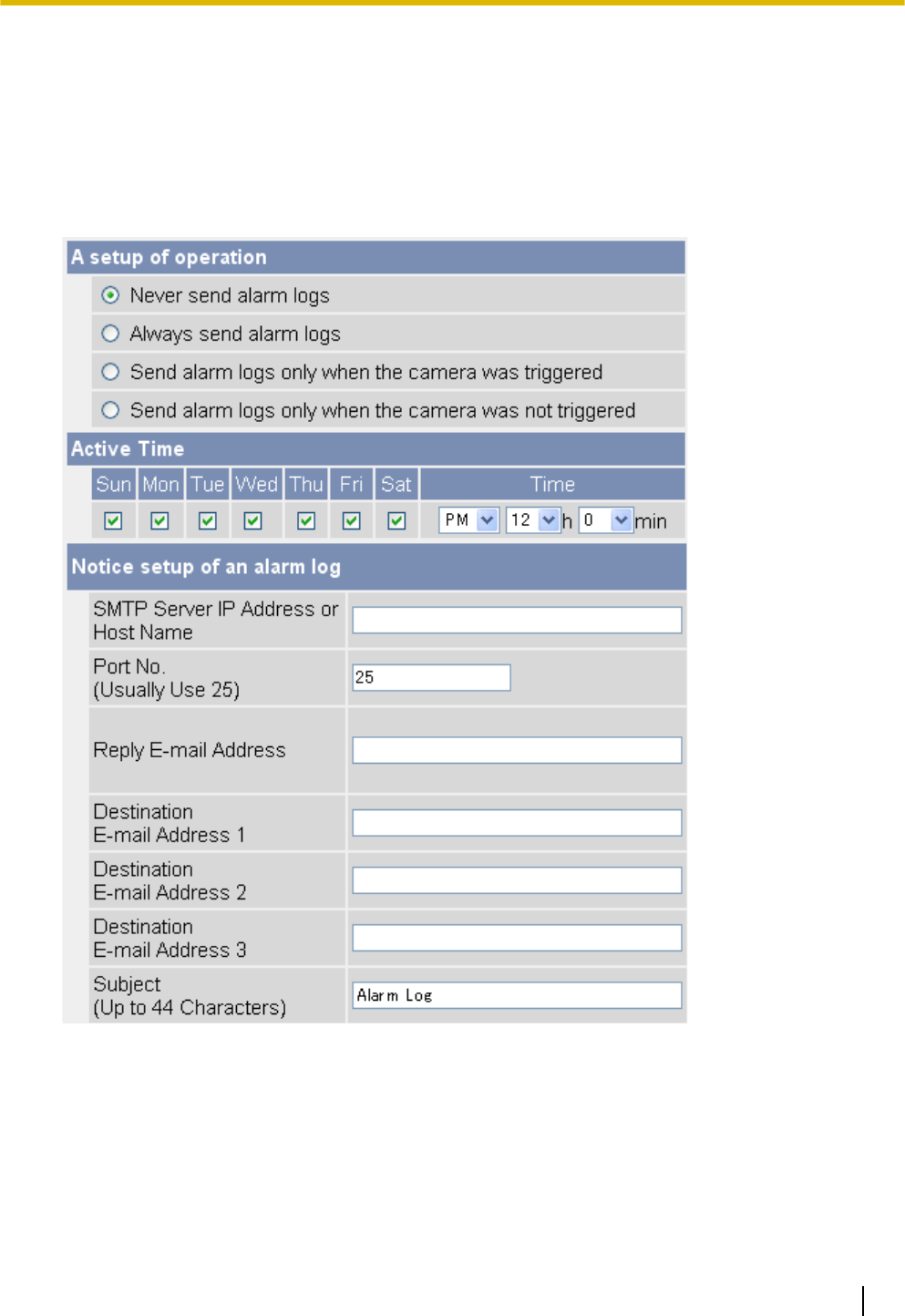
2.12 Sending Alarm Log Information
You can configure the camera to send a daily log by E-mail that reports the status of the built-in sensor, external
sensor, and detection triggers. This allows you to be notified by E-mail once a day and know whether or not
there were any events that triggered the camera. Ask your Internet Service Provider (ISP) or network
administrator for the appropriate settings.
1. Click the [Setup] tab.
2. On the left side of the screen under [Buffer/Transfer], click [Alarm Log].
3. Set the following parameters as desired.
a. Under [A setup of operation], select the desired setting.
–[Never send alarm logs]: Alarm logs will not be sent.
–[Always send alarm logs]: Alarm logs will be sent, even if the camera was not triggered.
–[Send alarm logs only when the camera was triggered]: Alarm logs will be sent if the camera was
triggered.
–[Send alarm logs only when the camera was not triggered]: Alarm logs will be sent only if the camera
was not triggered.
Operating Instructions 87
2.12 Sending Alarm Log Information
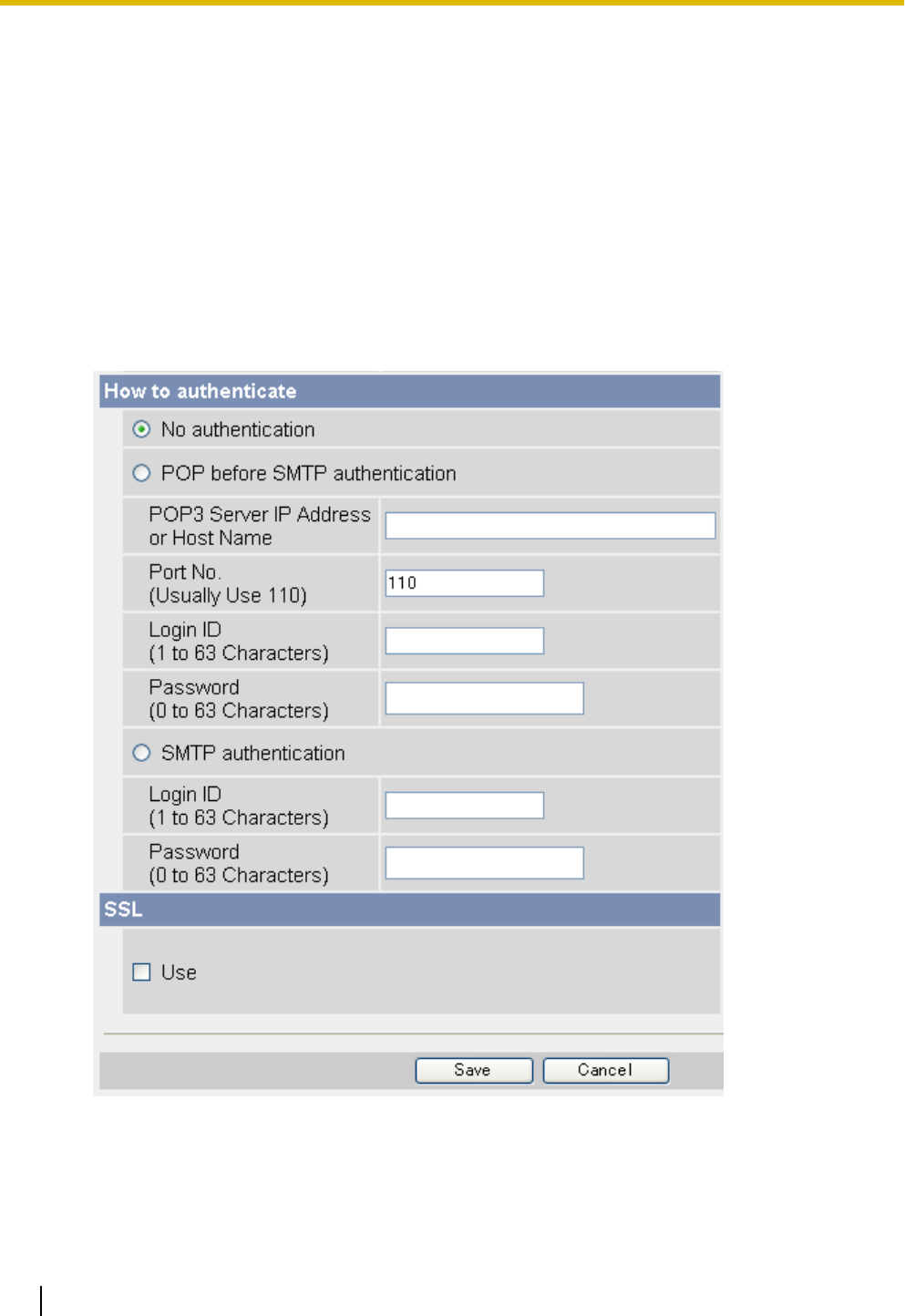
b. Under [Active Time], select the days and the time you want the camera to send alarm logs.
c. Under [Notice setup of an alarm log], enter the IP address or the host name*1 of the SMTP server
(outgoing mail server).
•An IPv6 address can be specified; note that the IPv6 address must be enclosed in brackets.
•This feature cannot transfer images to web-based mail servers, such as Hotmail.
d. Enter the port number used by the server. (Port 25 is normally used for sending E-mail.)
•Some ISPs require outgoing mail to be sent using port 587 or using SSL (SMTP over SSL) on port
465. Ask your ISP or network administrator for the appropriate setting.
e. Enter the reply E-mail address*2 that will be shown to the recipient as the sender of the E-mail.
•In an effort to reduce spam, many ISPs block E-mail sent through the SMTP server from an E-mail
address that is not associated with the SMTP server, therefore, we recommend entering the E-mail
address assigned to you by your ISP.
f. Enter the destination E-mail address*2. Up to 3 addresses can be entered.
g. Enter the subject*2 that will be displayed in E-mail messages sent by the camera (max. 44 characters).
4. Under [How to authenticate], select the authentication method your ISP requires for sending E-mail, and
enter the appropriate settings if necessary.
–[No authentication]: Select this option if the outgoing E-mail server does not require authentication
when sending E-mail messages.
88 Operating Instructions
2.12 Sending Alarm Log Information

–[POP before SMTP authentication]: Select this option if the outgoing E-mail server requires POP before
SMTP authentication when sending E-mail messages. The following settings are also necessary. Enter
the settings as you would for receiving E-mail.
a. Enter the IP address or the host name*1 of the POP3 server (incoming mail server).
•An IPv6 address can be specified; note that the IPv6 address must be enclosed in brackets.
b. Enter the port number used by the server. (Port 110 is normally used for POP3.)
c. Enter the login ID*2 (user name) required to access the server (max. 63 characters).
d. Enter the password*2 required to access the server (max. 63 characters).
–[SMTP authentication]: Select this option if the outgoing E-mail server requires SMTP authentication
when sending E-mail messages. The following settings are also necessary. Enter the settings as you
would for sending E-mail.
a. Enter the login ID*2 (user name) required to access the server (max. 63 characters).
b. Enter the password*2 required to access the server (max. 63 characters).
•The camera supports LOGIN, PLAIN, and CRAM-MD5 authentication.
5. Under [SSL], select [Use] if you want to use SSL encryption when sending E-mail.
•When [Use] is selected, the port number under [E-mail Transfer] may need to be set to 465. Ask your
ISP or network administrator for the appropriate settings.
•SSL supports SMTP over SSL. STARTTLS is not supported.
6. Click [Save], then click [Go to Alarm Log page].
Note
•When the settings are saved, the number of new alarm logs becomes 0.
*1 [Space], ["], ['], [&], [<], and [>] cannot be entered.
*2 ["] cannot be entered.
Operating Instructions 89
2.12 Sending Alarm Log Information

3 Mobile Phone Features
This section describes the features available when using a mobile phone that is compatible with Panasonic
Network Cameras. Before using any of these features, please read the following notes.
•Certain mobile phones are not compatible with Panasonic Network Cameras.
•Mobile phones that only allow the use of port number 80 or mobile phones that do not support password
authentication are not compatible with Panasonic Network Cameras.
•Certain mobile phones may not display images correctly.
•Video images cannot be displayed on mobile phones.
•The camera’s audio features are not available with mobile phones.
•Data packet fees may apply when accessing the camera from your mobile phone. Consult your mobile
service provider for more information.
90 Operating Instructions

3.1 Accessing the Camera from Your Mobile Phone
1. Enter http:// followed by the IP address of the camera and /mobile, then access the camera.
Example: http://***.***.***.***/mobile
•If the camera’s port number is a port number other than 80, enter “:” and the port number after the IP
address.
Example: http://***.***.***.***:50001/mobile
•If you have registered with a DNS service, such as Viewnetcam.com (see Page 105), enter the URL
instead of the IP address.
Example: http://***.viewnetcam.com
•If the camera is configured to use HTTPS (see Page 119), enter https:// followed by the IP address
or host name and the port number of the camera. Note, however, that certain mobile phones do not
support HTTPS connections.
Example: https://***.***.***.***:80/mobile
Example: https://***.viewnetcam.com:80/mobile
2. If an authentication dialog is displayed, enter the user name and password.
•A still image from the camera is displayed.
•If the camera image is not displayed properly, try accessing the camera by entering one of the following
instead of /mobile.
–/mobileh (for HTML)
–/mobilex (for XHTML)
Note
•If the camera is configured to allow access from guest users (i.e, anonymous users; see Page 155),
users can access the camera’s mobile phone pages using a mobile phone or PC without entering a
user name or password.
Operating Instructions 91
3.1 Accessing the Camera from Your Mobile Phone
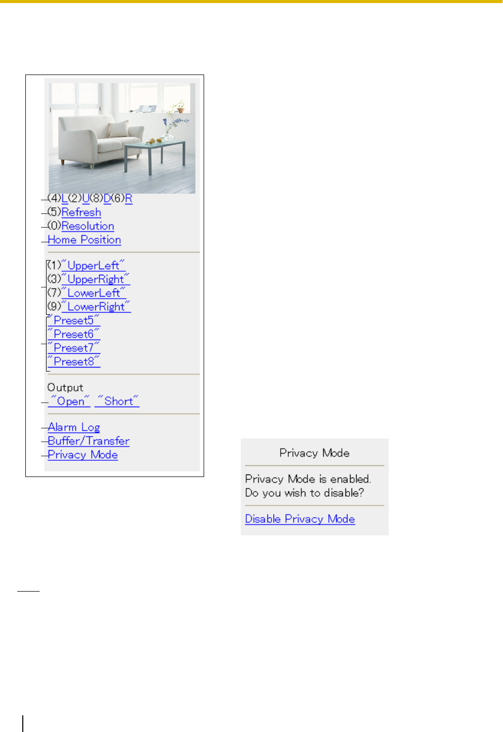
3.2 Viewing Still Images on Your Mobile Phone
Still images from the camera can be viewed with a compatible mobile phone.
A
B
C
D
H
I
J
F
G
E
A. Press [4] or [6] to pan the lens left or right, respectively, or
press [2] or [8] to tilt the lens up or down, respectively.
When the lens has reached the end of its pan or tilt range,
the corresponding number will not be displayed.
B. Press [5] to refresh the image.
C. Press [0] to toggle between the available image
resolutions (192 ´ 144 and 320 ´ 240). You can set the
default image resolution for when viewing with your mobile
phone (see Page 159).
D. Select [Home Position] to move the lens to the home
position.
E. Press [1], [3], [7] or [9] to move the lens to the first four
presets (presets 1–4).
F. For presets 5–8, select the corresponding preset name to
move the lens to the desired position.
G. BL-C230 only: Controls the output signals of the external
I/O interface (see Page 168).
H. Select [Alarm Log] to view the last 50 external sensor and
motion detection trigger logs (see Page 94).
•You must be logged in to the camera as an
administrator to use this feature.
I. Select [Buffer/Transfer] to view the image buffer and
transfer control page (see Page 95).
•You must be logged in to the camera as an
administrator to use this feature.
J. Select [Privacy Mode] to turn privacy mode on. (You may
be asked to enter the administrator user name and
password.) To turn privacy mode off, access the camera
again and select [Disable Privacy Mode].
•You must be logged in to the camera as an
administrator to use this feature.
Note
•When accessing the camera as a general user or as a guest user, certain features may be disabled
according to the [Access Level] set for the user (see Page 152 and Page 155).
•If the camera is configured to allow access from guest users (i.e., anonymous users; see Page 155),
users can access the camera’s mobile phone pages using a mobile phone or PC without entering a
user name or password. If guest user access is permitted, you can log in as the administrator by
selecting [Alarm Log], [Buffer/Transfer], or [Privacy Mode], and then entering the user name and
password when the authentication dialog is displayed.
92 Operating Instructions
3.2 Viewing Still Images on Your Mobile Phone

•If you turn privacy mode on, camera images are not buffered even if the camera is configured to buffer
images.
•Screen content varies by model number.
Operating Instructions 93
3.2 Viewing Still Images on Your Mobile Phone
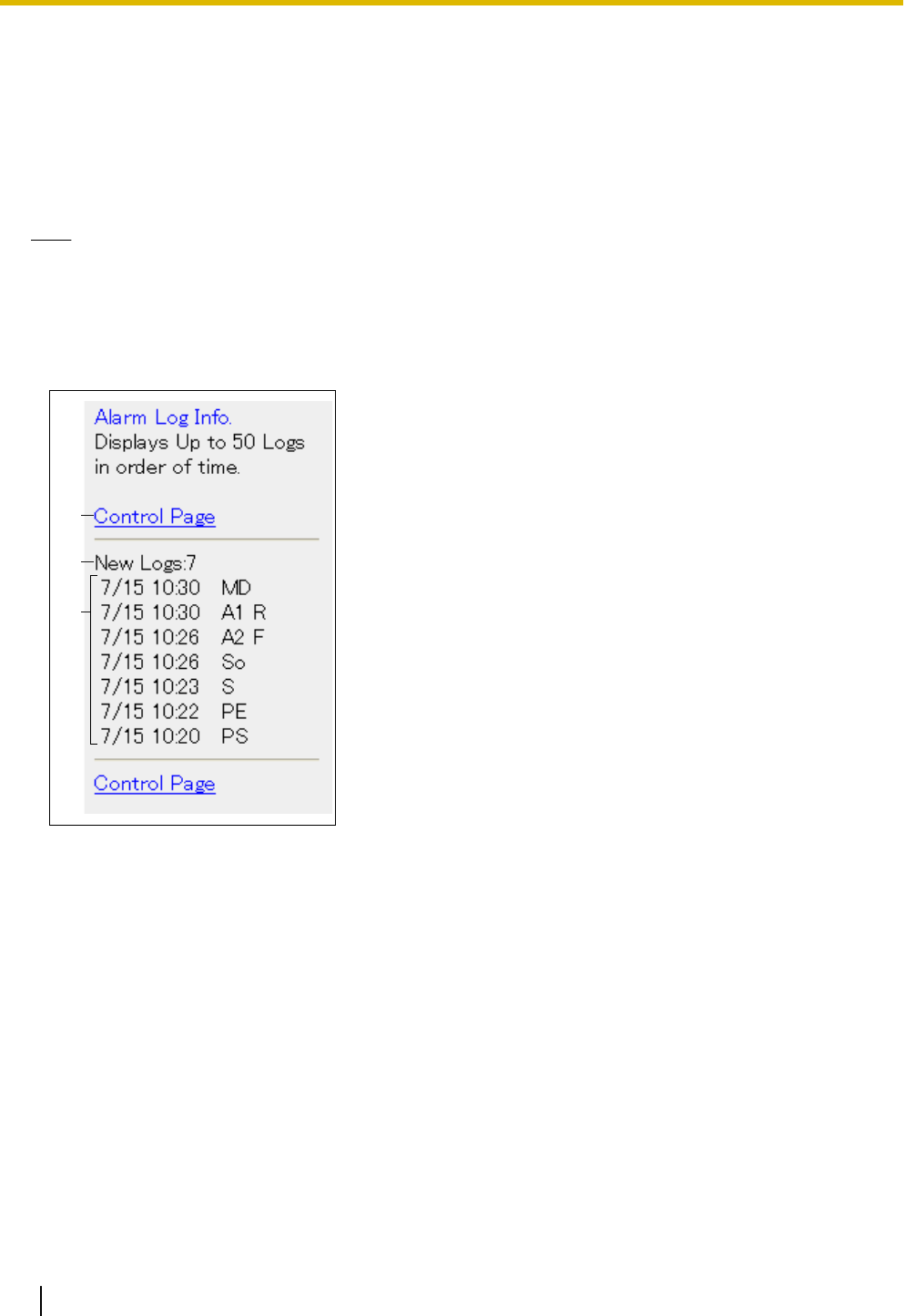
3.3 Viewing Alarm Logs on Your Mobile Phone
The camera records log information each time the camera is triggered and each time the camera’s privacy
feature is turned on and off. Up to 50 events are logged, and each event includes the date, time, and type
(built-in sensor, external sensor 1, external sensor 2, motion detection, sound detection, or privacy mode on/
off).
You can view the log while accessing the camera from your mobile phone.
Note
•You must be logged in to the camera as an administrator to use this feature.
1. Access the camera with your mobile phone (see Page 91).
2. Select [Alarm Log].
3. Confirm the alarm logs as necessary.
4. Select [Control Page] when finished to return to the previous screen.
A
B
C
A. Returns to the previous screen.
B. The number of new alarm logs is displayed.
C. The date and time of each log, and the type of each trigger is
displayed.
•The date is displayed in MM/DD format.
•The time is displayed in 24-hour format.
•[S] indicates a sensor detection.
•[So] indicates a sound detection.
•[MD] indicates a motion detection.
•[A1] indicates an external sensor 1 detection.
•[A2] indicates an external sensor 2 detection.
•[PS] indicates privacy mode starts.
•[PE] indicates privacy mode ends.
•[R] indicates [Rising: GND to Open (High).] signal type
(logical HIGH).
•[F] indicates [Falling: Open (High) to GND.] signal type
(logical LOW).
94 Operating Instructions
3.3 Viewing Alarm Logs on Your Mobile Phone
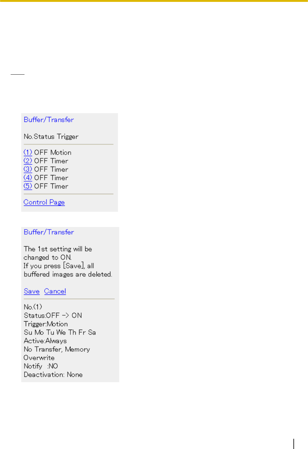
3.4 Enabling and Disabling Image Buffering Using
Your Mobile Phone
While accessing the camera from your mobile phone, select [Buffer/Transfer] to display the image buffer and
transfer control page on your mobile phone.
Note
•You must be logged in to the camera as an administrator to use this feature.
1. Access the camera with your mobile phone (see Page 91).
2. Select [Buffer/Transfer].
3. Select the desired trigger number to turn the trigger on or off.
4. Select [Save] to turn the selected trigger on or off.
•All images buffered in the memory are deleted when you click [Save].
5. Select [Control Page] when finished to return to the previous screen.
Operating Instructions 95
3.4 Enabling and Disabling Image Buffering Using Your Mobile Phone
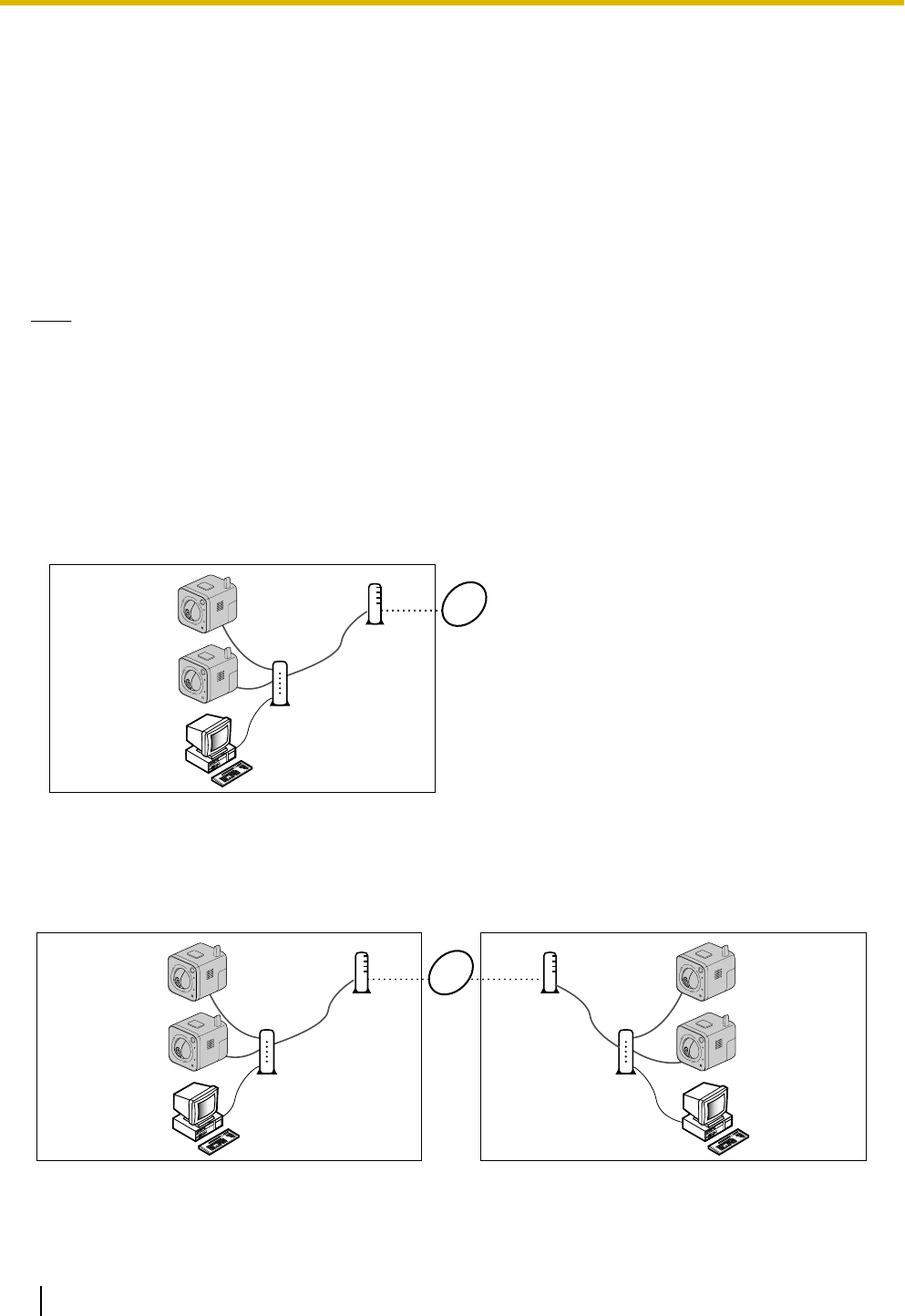
4 Configuring the Camera for Access from the
Internet
You can configure the camera to be accessed over the Internet, allowing you to view camera images and
change camera settings from anywhere—even using your mobile phone. This section explains the concepts
and procedures for configuring your camera (and other network devices) to allow you to view camera images
over the Internet.
Before you can configure the camera for access from the Internet, it is necessary to understand how IP
addresses and Internet connections work.
Note
•To configure the camera to be accessed over the Internet using IPv6, see Page 194.
Understanding local addresses
Each device connected to your computer network (PCs, router, network printers, network cameras, etc.) has
an IP address. It probably looks something like this: 192.168.0.100. Each IP address on your network must be
unique, as shown in the example below.
In this example, you would enter 192.168.0.253 or 192.168.0.252 in your web browser’s address bar to access
your cameras with your PC.
192.168.0.2
192.168.0.252
192.168.0.253
192.168.0.1
A
B
C
AInternet
BModem
CRouter
Although each IP address on your network must be unique, the addresses are unique only to your network. In
other words, your cameras and your neighbor’s cameras may have the same IP addresses. In the example
below, the addresses of your devices (on the left) and the addresses of your neighbor’s devices (on the right)
are the same, but this is not a problem because the cameras are not connected to the same network.
C
B
192.168.0.2
192.168.0.252
192.168.0.253
192.168.0.2
192.168.0.252
192.168.0.253
192.168.0.1192.168.0.1
A
B
C
IP addresses that distinguish different devices on the same LAN (local area network, i.e., personal network)
are called local IP addresses. The IP addresses in the examples above are local IP addresses.
96 Operating Instructions
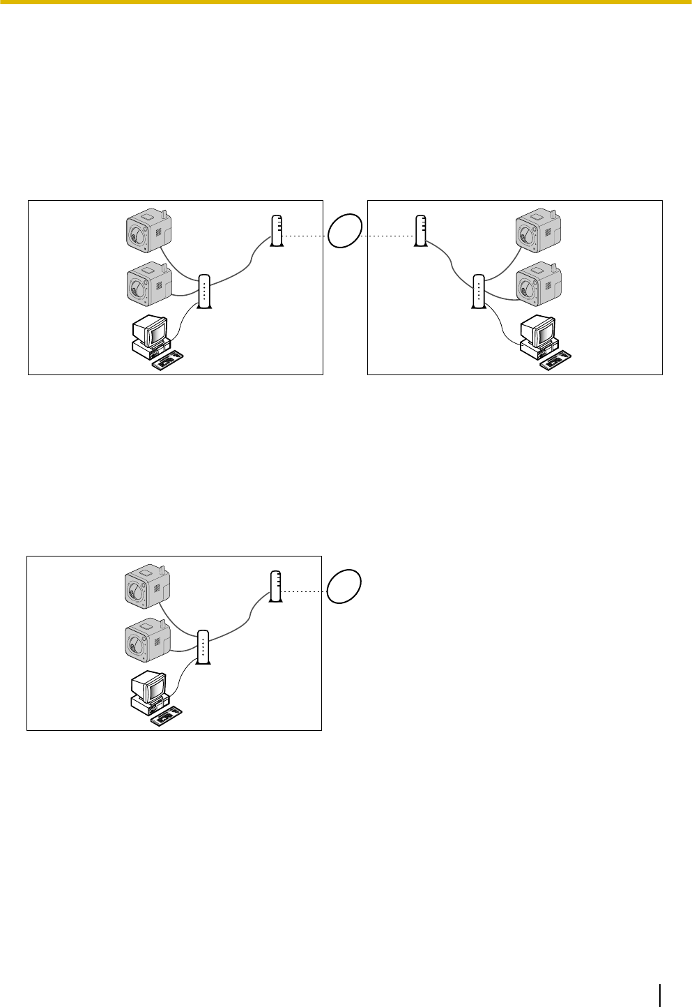
So how can you access your camera when you are away from home if other people are using the same IP
address as your camera?
Understanding global addresses
The answer is to access the camera by entering the unique IP address assigned to you by your Internet Service
Provider (ISP). This address is called a global address, or a WAN (wide area network) address. In the example
below, your global IP address is aaa.aaa.aaa.aaa and your neighbor’s global IP address is zzz.zzz.zzz.zzz.
•Note that an actual IP address is made of numbers, not letters.
C
B
192.168.0.2
192.168.0.252
192.168.0.253
192.168.0.2
192.168.0.252
192.168.0.253
192.168.0.1
zzz.zzz.zzz.zzz
192.168.0.1
aaa.aaa.aaa.aaa
A
B
C
When you are away from home, you can access your router by entering aaa.aaa.aaa.aaa. But now you have
another problem—you don’t want to access your router, you want to access the cameras connected to your
routers.
Understanding port numbers
Data is sent between devices on a network using different ports depending on what kind of data is being sent.
A port is not a physical object; it is a piece of information in the data that helps the data be directed to the
intended device. In the example below, the port numbers 50000 and 50001 are assigned to your cameras.
192.168.0.2
192.168.0.252
Port 50001
192.168.0.253
Port 50000
192.168.0.1
A
B
C
aaa.aaa.aaa.aaa
By assigning unique port numbers to your cameras, you can access your cameras when you are away from
home by entering aaa.aaa.aaa.aaa:50000 or aaa.aaa.aaa.aaa:50001 in the web browser of a PC. When your
router receives information via its global IP address, it passes it on to one of your cameras depending on which
port number you entered after the global IP address.
But how does your router know which camera to pass information to?
Understanding port forwarding
If your router supports a feature called port forwarding (sometimes it’s called address translation, static IP
masquerade, virtual server, port mapping, or other names, depending on the router manufacturer), the router
can be set up to take information it receives on specific ports and pass it on to a specific IP address.
The port forwarding settings needed for the example above would look something like this:
Operating Instructions 97
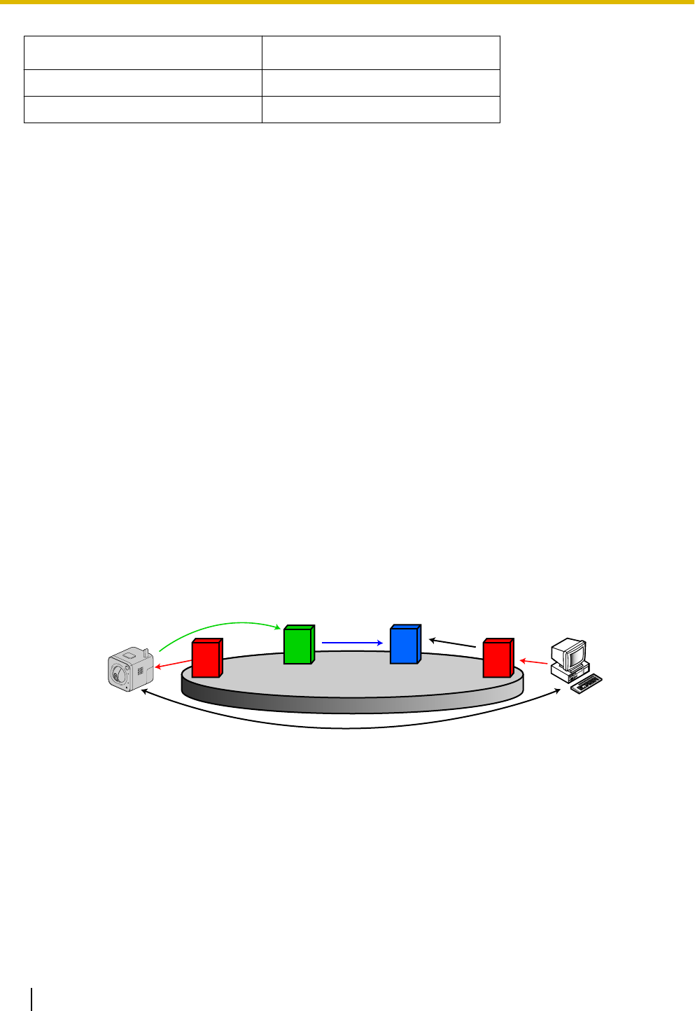
Port No. of Incoming Access Forwarding Destination
50000 192.168.0.253:50000
50001 192.168.0.252:50001
Now you may be thinking, “do I have to do this programming by myself?”
Understanding UPnP™
If your router does not support a feature called UPnP™ (Universal Plug and Play), you will have to manually
configure your router for port forwarding. Refer to the operating instructions included with your router for more
information.
If your router does support UPnP™, your cameras and router can communicate with each other so that the
router knows which ports are used by which camera. This means you will be able to access your cameras from
the Internet without having to configure your router manually.
Understanding Dynamic DNS services
There is one last problem to solve. How do you find out the global address your ISP has assigned to you? The
answer is to first contact them. If your provider has assigned you a static IP address (i.e., an IP address that
never changes), you can use that static address to access your cameras from the Internet as long as your
router is set up for port forwarding.
But most service providers use dynamic addresses, which means your global address may change monthly,
weekly, or maybe even every day. If your provider uses dynamic addresses, you will need to register with a
Dynamic DNS service in order to access your camera from the Internet.
A Dynamic DNS service allows you to use an easy-to-remember address (such as ***.viewnetcam.com)
to access your camera from the Internet. If you have subscribed to a Dynamic DNS service and configured
your camera to use that Dynamic DNS service, your camera will notify the Dynamic DNS service each time
your provider changes your global IP address. This means your Dynamic DNS service always knows your
current global address, so whenever you enter your easy-to-remember address, the Dynamic DNS service
automatically passes the information on to your router, and ultimately, your camera.
Example of how a Dynamic DNS service helps you access your camera over the Internet
1
B
CD
B
B
CD
B
4
3
6
52
A
A
AInternet BISP CDynamic DNS Service DDNS Server
1. Your ISP assigns a new global IP address to your Internet access account.
2. The camera notifies your Dynamic DNS service of its new global IP address.
3. The Dynamic DNS service notifies the DNS server of your new global IP address. The DNS server updates
its information so that your URL (for example, ***.viewnetcam.com) is registered to your new global
IP address.
4. You try to access your camera from outside (i.e., over the Internet) by entering ***.viewnetcam.com.
5. The computer contacts the DNS server and requests the global IP address registered to
***.viewnetcam.com. The DNS server looks up the global IP address of your URL.
98 Operating Instructions

6. The computer receives your current global IP address from the DNS server and accesses the camera.
Summary
In order to access your camera over the Internet, you need to do the following.
1. Configure your router for port forwarding. If your router supports UPnP™, this can be done automatically.
Refer to the operating instructions included with your router for information on UPnP™ support (the
router’s UPnP™ feature may be turned off by default) or for information on setting port forwarding.
2. If your ISP has assigned you a dynamic global IP address, register with a Dynamic DNS service. We
recommend using Viewnetcam.com, a Dynamic DNS service that is designed for use with Panasonic
Network Cameras. (For more information, refer to the Viewnetcam.com website at
http://www.viewnetcam.com.)
3. After you have registered with a Dynamic DNS service, configure the camera to use that service.
Operating Instructions 99

4.1 Configuring Port Forwarding
In order to access your camera from the Internet, you will need to configure your router for port forwarding. If
your router supports UPnP™ (Universal Plug and Play), the camera and router can communicate with each
other and set port forwarding automatically. This can be done during initial configuration (as explained in the
Setup Guide), or by following one of the procedures below.
There are two methods you can use to configure port forwarding via UPnP™.
–Using the [Internet] tab (recommended)
Using this method, the camera’s current port number may change. The camera will be assigned a port
number that is not currently used by another device on the network. If port 80 is unavailable, the camera
will be assigned the first available port number between 50000 and 50050.
To use this method, see Page 101.
–Using the [UPnP] page
Using this method, the camera’s port number will not change.
To use this method, see Page 102.
Note
•If your router does not support UPnP™, you need to configure the router’s port forwarding feature
manually. See Page 102.
•If your router’s UPnP™ feature is turned off (most routers have UPnP™ turned off by default), you
need to turn it on in order to configure port forwarding automatically. Refer to the operating instructions
included with your router and the Panasonic Network Camera website
(http://panasonic.net/pcc/support/netwkcam/) for more information.
•If you have a PPPoE or PPTP connection to your Internet Service Provider, disable your router’s
maximum idle time setting. Refer to the operating instructions included with your router for more
information.
•UPnP™ features are available when using the camera in IPv4. The camera does not support UPnP
™ for IPv6 connections.
100 Operating Instructions
4.1 Configuring Port Forwarding
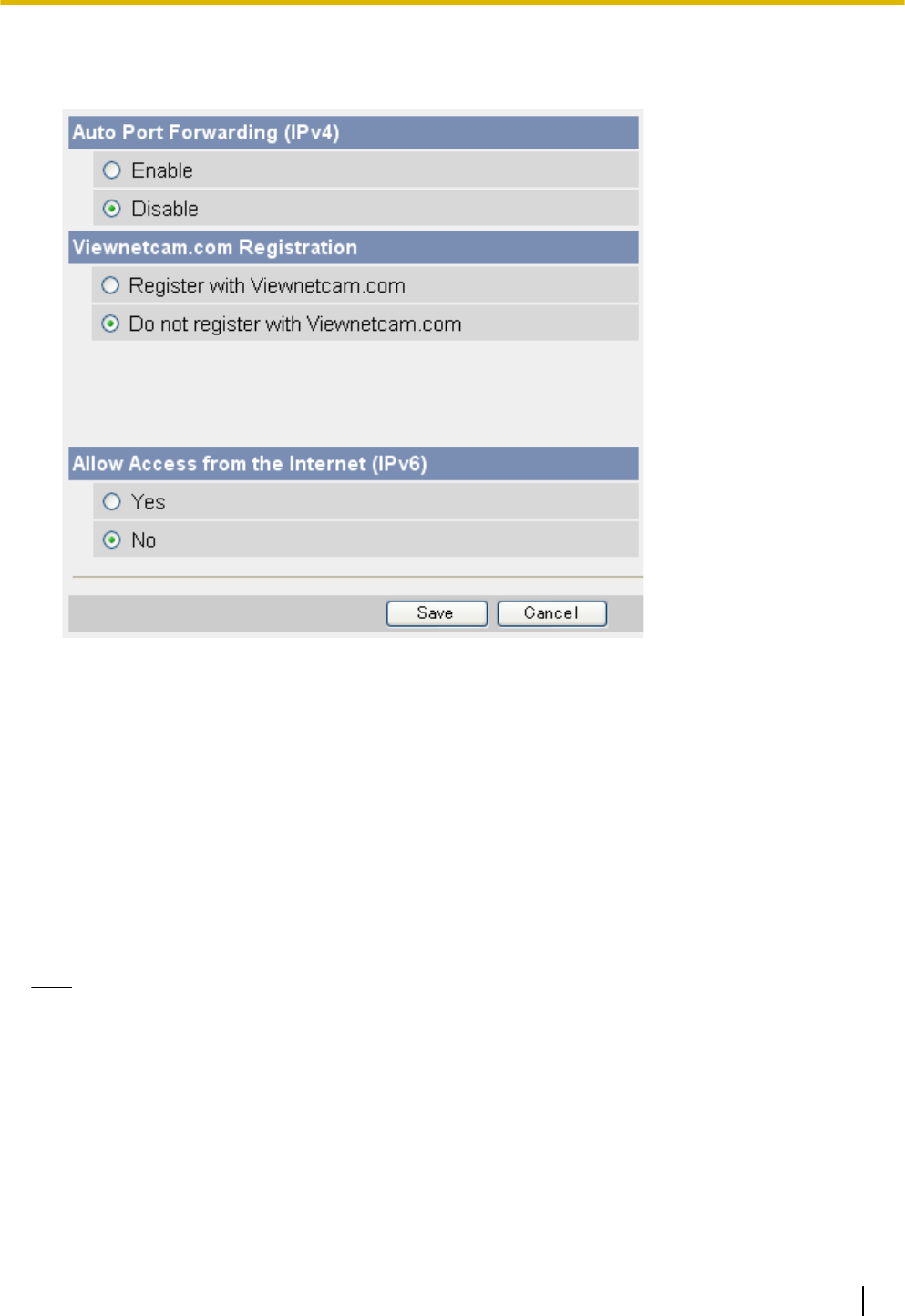
Enabling [Auto Port Forwarding] using the [Internet] tab
1. Click the [Internet] tab.
2. Under [Auto Port Forwarding (IPv4)], select [Enable].
3. Click [Save].
•A notice is displayed informing you that the camera’s port number may change.
4. Click [OK].
•[Router configuration in progress to allow access from the Internet.] is displayed.
•If you want to register with Viewnetcam.com (visit http://www.viewnetcam.com for details), select
[Register with Viewnetcam.com] before clicking [Save]. Click [Go to Viewnetcam.com Registration
page] when this button is displayed. The Viewnetcam.com website will open in a new window. Follow
the on-screen instructions to register with Viewnetcam.com.
•When [Setup completed] is displayed, the addresses for accessing the camera over the LAN and over
the Internet are displayed.
5. Click [To Single Camera page].
6. Confirm that port forwarding was configured correctly (see Page 102).
Note
•If you have multiple cameras connected to the same network, only one of the cameras needs to be
registered with Viewnetcam.com. All cameras connected to the network can be accessed from the
Internet using your Viewnetcam.com URL (for example, ***.viewnetcam.com) and adding the
desired camera’s port number after the URL. Example: http://***.viewnetcam.com:50000,
http://***.viewnetcam.com:50001, etc. Note, however, if the camera that is registered to
Viewnetcam.com is turned off and your ISP-provided global IP address changes, you will not be able
to access any of the cameras.
•To disable Viewnetcam.com service for this camera later, access the Viewnetcam.com website
(http://www.viewnetcam.com) and cancel your registration.
•If auto port forwarding is enabled or disabled on this page, it is also enabled or disabled on the
[UPnP] page.
Operating Instructions 101
4.1 Configuring Port Forwarding
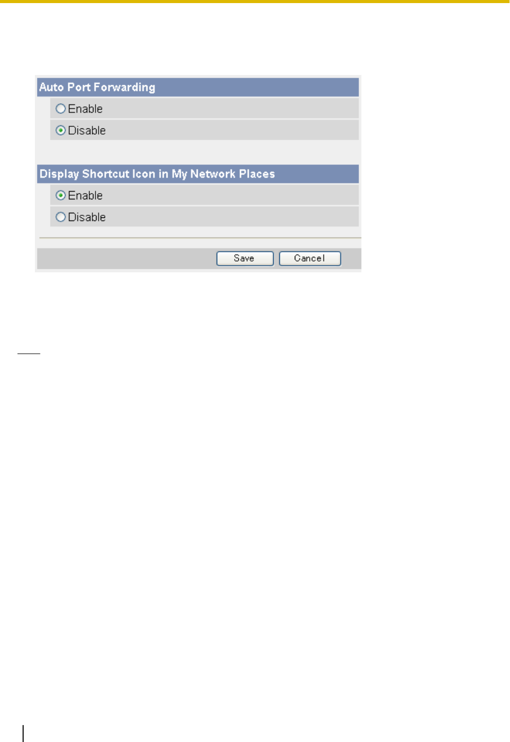
Enabling [Auto Port Forwarding] using the [UPnP] page
1. Click the [Setup] tab.
2. On the left side of the screen under [Basic], click [UPnP].
3. Under [Auto Port Forwarding], select [Enable].
4. Click [Save].
•When setup is complete, [Success!] is displayed.
5. Confirm that port forwarding was configured correctly (see Page 102).
Note
•If auto port forwarding is enabled or disabled on this page, it is also enabled or disabled on the
[Internet] tab.
•Screen content varies by model number.
Confirming that UPnP™ port forwarding is configured correctly
To confirm that the UPnP™ port forwarding has been successfully configured, follow the procedure below.
1. Click the [Maintenance] tab.
2. On the left side of the screen, click [Status].
3. Under [UPnP], confirm that the status is [Enabled].
•If [Enabled] is not displayed, refer to the UPnP™ related items in 1.3 Camera Setup Issues and
1.5 Camera Access Issues in the Troubleshooting Guide.
Configuring port forwarding without using UPnP™
If your router does not support UPnP™, you need to configure the router’s port forwarding feature manually.
1. Click the [Setup] tab.
2. On the left side of the screen under [Basic], click [Network (IPv4)].
3. Under [Connection Mode], click [Static].
4. Make a note of the IP address and port number displayed here. You will need to know these settings when
configuring the router for port forwarding.
5. Click [Save].
6. Click [Restart].
102 Operating Instructions
4.1 Configuring Port Forwarding

7. While referring to the operating instructions included with your router, configure the router’s port forwarding
feature.
•When configuring port forwarding, store the camera’s IP address and port number that you noted
above.
8. Register the camera to use a Dynamic DNS service, such as Viewnetcam.com (see Page 105).
Operating Instructions 103
4.1 Configuring Port Forwarding

4.2 Configuring the Camera to Use a Dynamic DNS
Service
You can configure the camera to use Viewnetcam.com (see Page 105) or a third-party Dynamic DNS service
(see Page 109).
A Dynamic DNS service is a service that allows you to assign an easy-to-remember URL (web address) to the
camera, such as ***.viewnetcam.com, allowing you to access the camera from the Internet using your
personalized URL. A Dynamic DNS service also allows you to easily access the camera, even when your
Internet Service Provider changes your IP address, because the camera periodically contacts the Dynamic
DNS service and notifies the service of its current address.
If you are interested in accessing your camera over the Internet, we recommend using a Dynamic DNS service,
such as Viewnetcam.com. For more information about Viewnetcam.com, please visit
http://www.viewnetcam.com for details.
104 Operating Instructions
4.2 Configuring the Camera to Use a Dynamic DNS Service
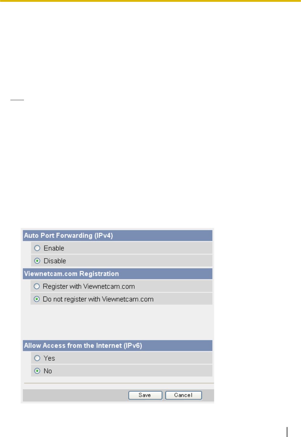
4.2.1 Configuring the Camera to Use Viewnetcam.com
If you are interested in accessing your camera over the Internet, we recommend using Viewnetcam.com.
Viewnetcam.com is a Dynamic DNS service designed for use with Panasonic Network Cameras. For more
information about Viewnetcam.com, please visit http://www.viewnetcam.com for details.
There are two methods you can use to configure the camera to use Viewnetcam.com.
–Using the [Internet] tab (recommended)
To use this method, see Page 105.
–Using the [DynamicDNS] page
To use this method, see Page 106.
Note
•If your router supports UPnP™ and you want to enable auto port forwarding as well as use
Viewnetcam.com, use the procedure described in Page 101.
•If you have multiple cameras connected to the same network, only one of the cameras needs to be
registered with Viewnetcam.com. All cameras connected to the network can be accessed from the
Internet using your Viewnetcam.com URL (for example, ***.viewnetcam.com) and adding the
desired camera’s port number after the URL. Example: http://***.viewnetcam.com:50000,
http://***.viewnetcam.com:50001, etc. Note, however, if the camera that is registered to
Viewnetcam.com is turned off and your ISP-provided global IP address changes, you will not be able
to access any of the cameras.
•To disable Viewnetcam.com service for this camera later, access the Viewnetcam.com website
(http://www.viewnetcam.com) and cancel your registration.
•It may take up to 30 minutes before the camera can be accessed over the Internet.
Configuring the camera to use Viewnetcam.com from the [Internet] tab
1. Click the [Internet] tab.
Operating Instructions 105
4.2.1 Configuring the Camera to Use Viewnetcam.com
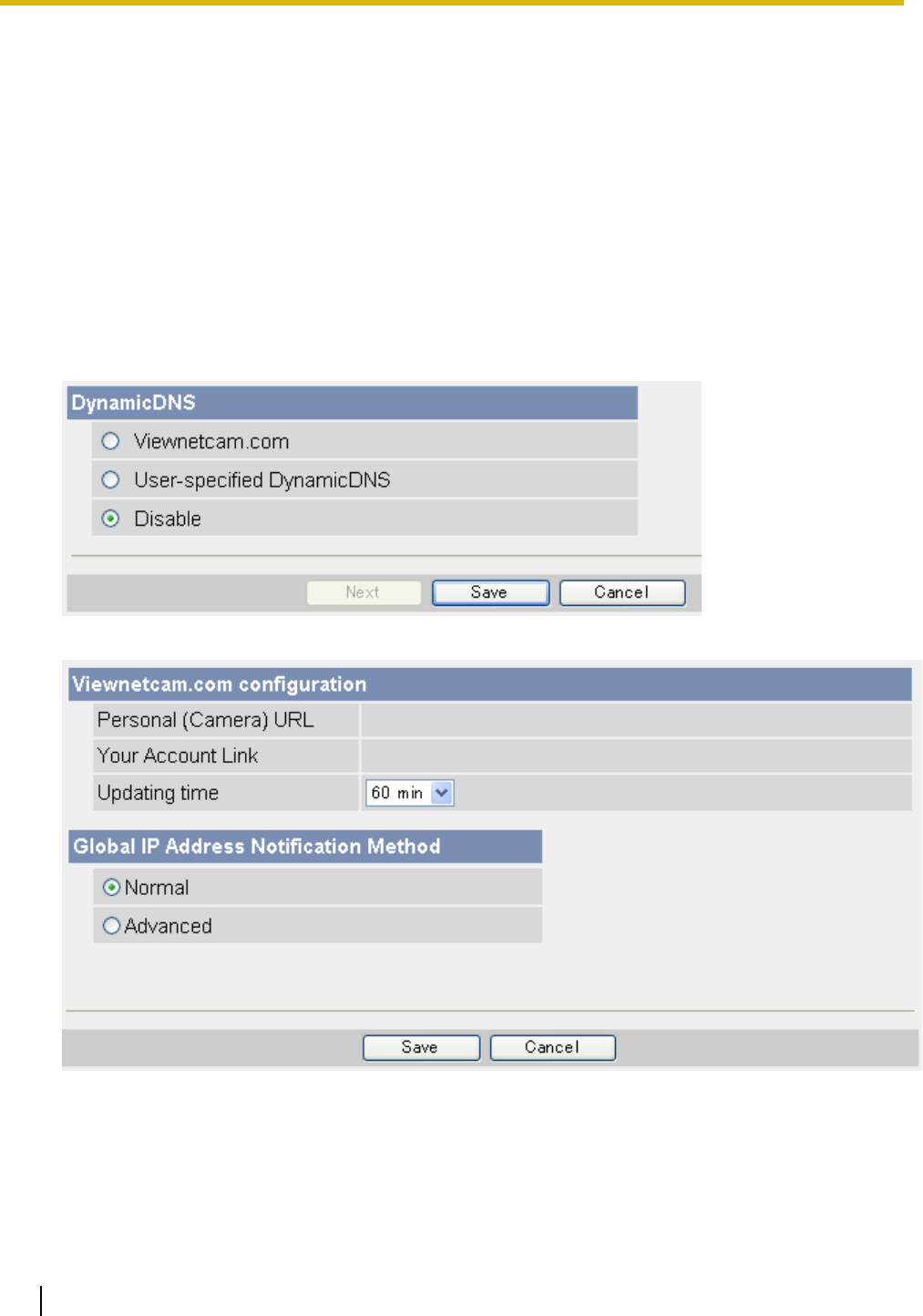
2. Under [Viewnetcam.com Registration], select [Register with Viewnetcam.com].
3. Click [Save].
4. When [Setup completed] is displayed, click [Go to Viewnetcam.com Registration page].
•The Viewnetcam.com website is displayed. Follow the on-screen instructions to register with
Viewnetcam.com.
•When [Setup completed] is displayed, the addresses for accessing the camera over the LAN and over
the Internet are displayed.
5. Click [To Single Camera page].
Configuring the camera to use Viewnetcam.com from the [DynamicDNS]
page
1. Click the [Setup] tab.
2. On the left side of the screen under [Basic], click [DynamicDNS].
3. Select [Viewnetcam.com], then click [Next].
4. Click [Save].
•When setup is complete, [Success!] is displayed.
106 Operating Instructions
4.2.1 Configuring the Camera to Use Viewnetcam.com
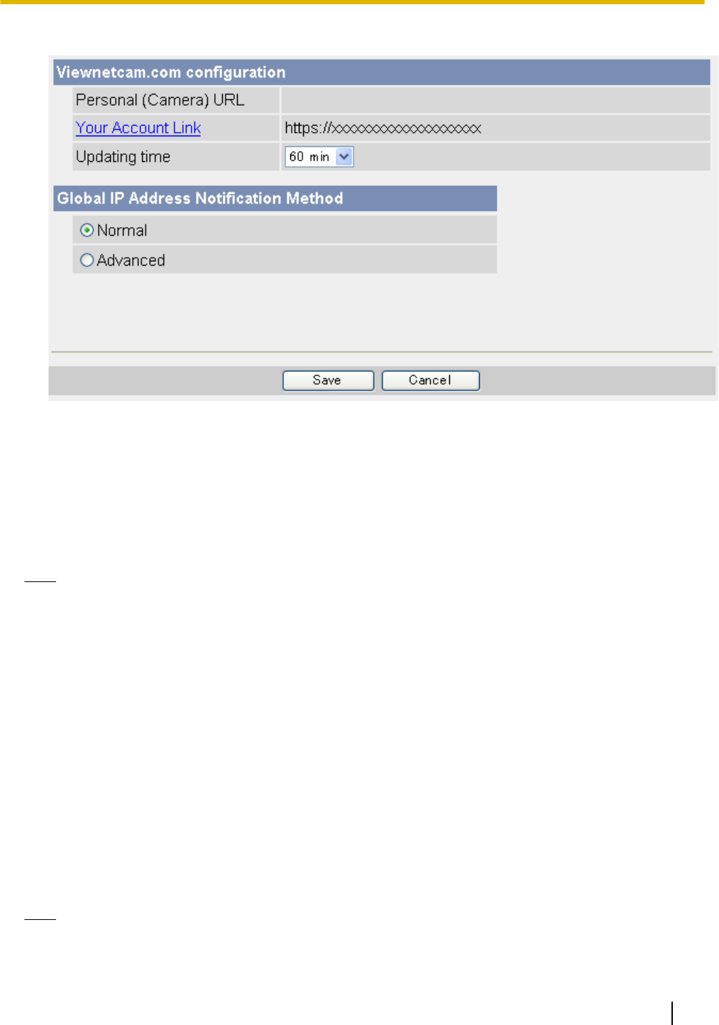
5. Click [Go to Viewnetcam.com page].
6. Click [Your Account Link].
7. The Viewnetcam.com website is displayed. Follow the on-screen instructions to register with
Viewnetcam.com.
•If the Viewnetcam.com website is not displayed, confirm that your PC can access the Internet, then
click your web browser’s refresh button.
•When registration is complete, you can access the camera using the Viewnetcam.com URL you
selected during registration. Note that you can access the camera using this URL only from a PC that
is not connected to the same network (LAN) as the camera.
Note
•If you have already registered with Viewnetcam.com, your personalized URL is displayed. This is the
address you can use to access the camera over the Internet. You can also access the URL displayed
next to [Your Account Link] to view your Viewnetcam.com registration information.
•If [Your Account Link] is not displayed, confirm that you have registered with Viewnetcam.com and that
your PC can access the Internet, then click your web browser’s refresh button.
•Typically [Global IP Address Notification Method] should be set to [Normal]. If you cannot access the
camera using the registered URL 30 minutes after registering with Viewnetcam.com, select
[Advanced]. In this case, UPnP must be enabled for the camera and for the router.
•If the global IP address of the router changes frequently, the camera may not be able to be accessed
over the Internet. In this case, set the [Updating time] setting to a lower (shorter) value.
Confirming your Viewnetcam.com registration
You can confirm that the camera has been successfully registered to Viewnetcam.com.
1. Click the [Maintenance] tab.
2. On the left side of the screen under [Maintenance], click [Status].
3. Under [Viewnetcam.com], confirm that [Enabled (2)] is displayed.
Note
•If the status is displayed as [Expiration], confirm that you have registered with Viewnetcam.com, or
restart the camera and access this page again.
Operating Instructions 107
4.2.1 Configuring the Camera to Use Viewnetcam.com

Changing the Viewnetcam.com address update time
You can select how often the camera notifies the Viewnetcam.com server of its current global IP address.
1. Click the [Setup] tab.
2. On the left side of the screen under [Basic], click [DynamicDNS].
3. Select [Viewnetcam.com], then click [Next].
4. Select the desired setting for [Updating time].
5. Click [Save].
108 Operating Instructions
4.2.1 Configuring the Camera to Use Viewnetcam.com
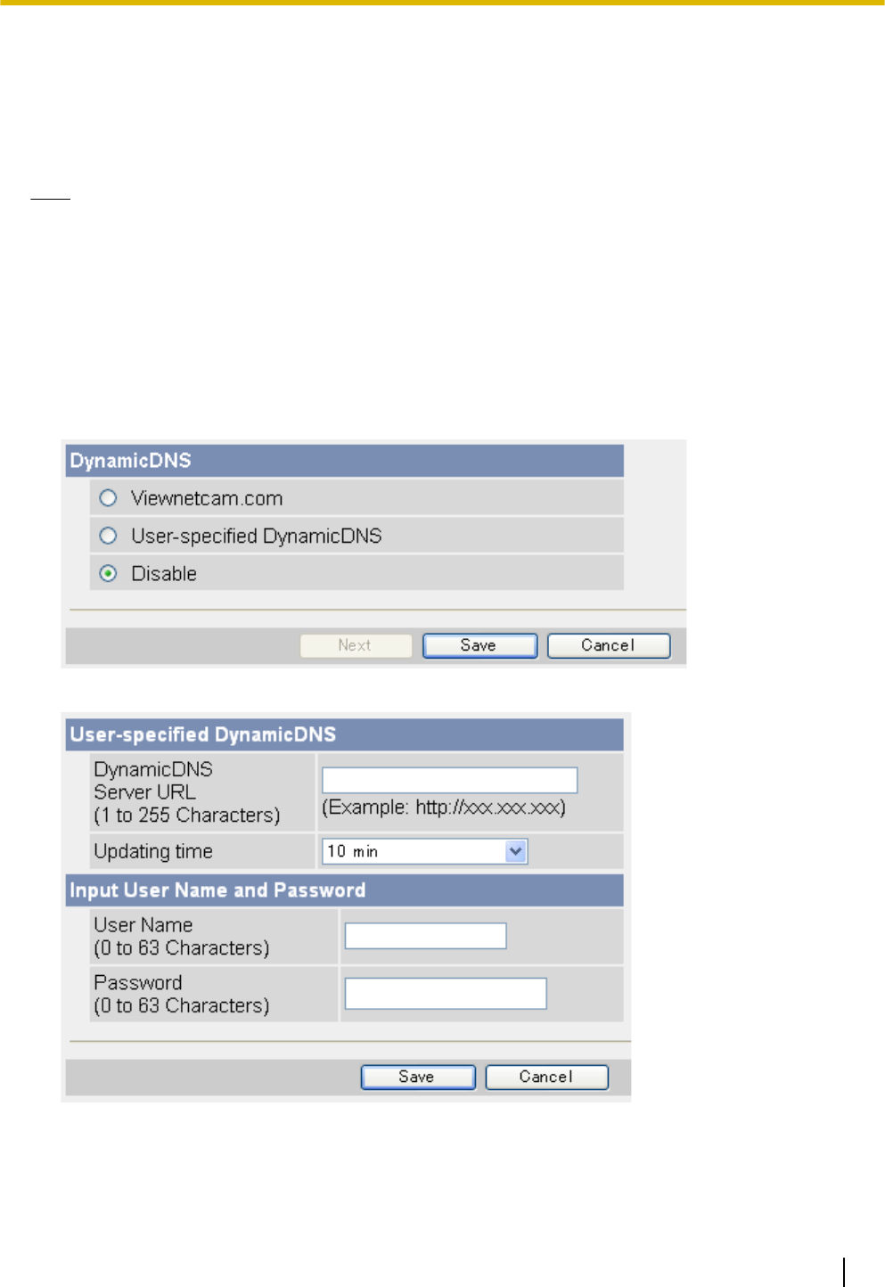
4.2.2 Configuring the Camera to Use a Third-party Dynamic DNS
Service
Before configuring the camera to use a third-party Dynamic DNS service, you will first need to subscribe to the
desired service. Ask the Dynamic DNS service provider for the settings required to use that service.
Note
•Certain third-party Dynamic DNS services may not be compatible with your camera. We cannot
guarantee that your camera will be compatible with third-party Dynamic DNS services, and therefore
we cannot take responsibility for any damage or performance issues that may occur when using a
Dynamic DNS service other than Viewnetcam.com (see Page 105).
•Please direct any questions you may have regarding the settings required to use a third-party Dynamic
DNS service to the Dynamic DNS service provider.
•After configuring the camera to use a third-party Dynamic DNS service, it may take several minutes
before the camera can be accessed over the Internet.
1. Click the [Setup] tab.
2. On the left side of the screen under [Basic], click [DynamicDNS].
3. Select [User-specified DynamicDNS], then click [Next].
4. Enter the URL (including http://)*1 provided or required by your Dynamic DNS service provider (max.
255 characters).
5. Select how often the camera notifies the Dynamic DNS service of its current global IP address.
6. Enter the user name*2 provided by the Dynamic DNS service provider (max. 63 characters).
Operating Instructions 109
4.2.2 Configuring the Camera to Use a Third-party Dynamic DNS Service
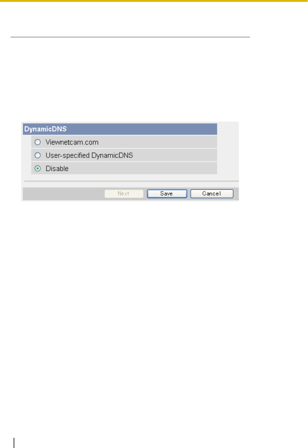
7. Enter the password*2 provided by the Dynamic DNS service provider (max. 63 characters).
8. Click [Save].
*1 [Space] and ["] cannot be entered.
*2 ["] and [:] cannot be entered.
Canceling the camera’s access to the Dynamic DNS service
Use the following procedure to stop the camera from notifying the Dynamic DNS service when your global IP
address changes. Note that if you intend to stop using the Dynamic DNS service altogether, you may need to
contact the Dynamic DNS service provider in order to cancel your subscription.
1. Click the [Setup] tab.
2. On the left side of the screen under [Basic], click [DynamicDNS].
3. Select [Disable], then click [Save].
110 Operating Instructions
4.2.2 Configuring the Camera to Use a Third-party Dynamic DNS Service

4.3 Confirming Internet Access
After configuring the camera to use a Dynamic DNS service and configuring your router for port forwarding,
confirm that the camera can be accessed over the Internet.
Most routers will not allow you to access a camera over the Internet using a PC connected to the same LAN
as the camera. To confirm that the camera can be accessed over the Internet, try accessing the camera using
a PC connected to a different network or by using your mobile phone (see Page 91).
Operating Instructions 111
4.3 Confirming Internet Access

5 Changing Camera Settings
5.1 Network Settings
The camera’s network settings are made when configuring the camera according to the instructions provided
in the Setup Guide. You can change these settings later if necessary using the procedures described in this
section.
Note
•You must log in to the camera as the administrator in order to change these settings.
•After changing network settings and clicking [Save], the camera must be restarted. All images buffered
in the internal memory are deleted when the camera is restarted.
•Ask your Internet Service Provider or network administrator for the appropriate network settings.
•If you cannot access the camera after changing certain network settings, use the Setup Program to
confirm the camera’s IP address (see Page 202) or reconfigure the camera as explained in the Setup
Guide.
•If your network uses the IPv6 protocol, see Page 187.
112 Operating Instructions
5.1 Network Settings
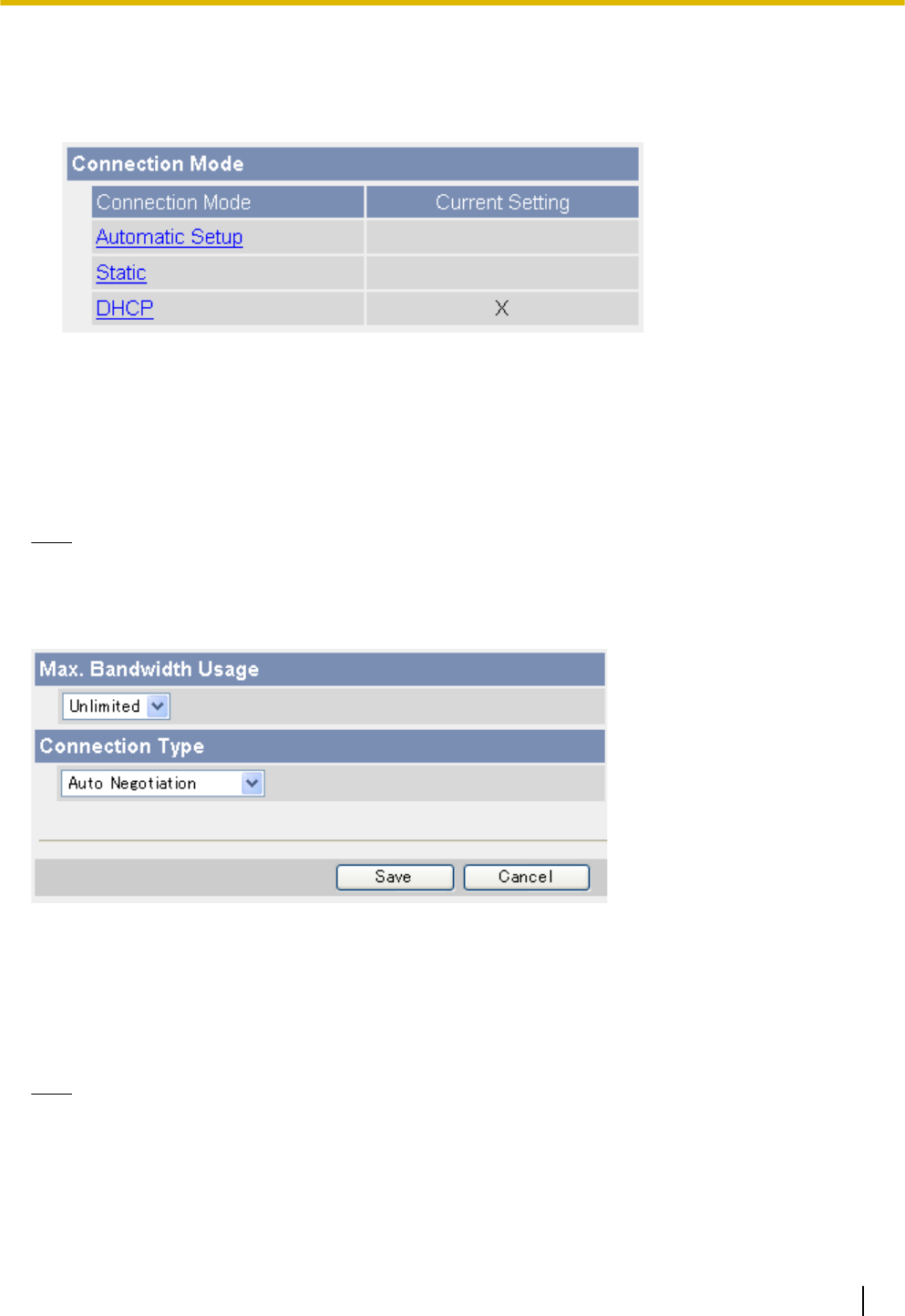
5.1.1 Network (IPv4) Settings
1. Click the [Setup] tab.
2. On the left side of the screen under [Basic], click [Network (IPv4)].
3. Select the desired connection mode, then make the appropriate settings as described in this section.
–[Automatic Setup]: Allows the camera to automatically obtain the appropriate network settings from
your broadband router or from your Internet Service Provider (ISP). The camera also searches for an
unused IP address on your network.
–[Static]: Allows you to set all network settings manually.
–[DHCP]: Allows you to specify your network settings (if necessary), after which the camera obtains an
IP address automatically from the DHCP feature of your broadband router or from your ISP.
Note
•Screen content varies by model number.
[Automatic Setup]
1. Set the following parameters as desired.
a. Under [Max. Bandwidth Usage], select the maximum bandwidth you want to allow the camera to use.
b. Under [Connection Type], select the appropriate connection type.
•Normally you can leave this setting at [Auto Negotiation].
2. Click [Save].
3. When the [New settings are saved.] message is displayed, click [Restart].
Note
•If the camera’s IP address was changed as a result of changing the network settings, use the Setup
Program on the CD-ROM to find the camera’s new IP address (see Page 202).
•The current network settings can be confirmed on the [Status] page (see Page 176).
Operating Instructions 113
5.1.1 Network (IPv4) Settings
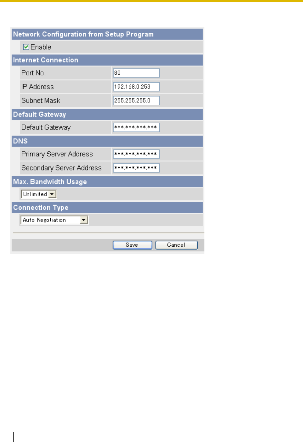
[Static]
1. Set the following parameters as desired.
a. Under [Network Configuration from Setup Program], select whether or not you want to allow the camera
to be configured using the Setup Program on the CD-ROM.
b. Under [Internet Connection], enter the port number to be assigned to the camera.
•The default port number is 80, however, note that some ISPs do not allow access from the Internet
using port 80. Ask your ISP or network administrator about which port numbers are available for
access over the Internet.
•Do not use the following port numbers:
–20 and 21: used for FTP
–23: used for Telnet
–25: used for SMTP
–53: used for DNS
–110: used for POP3
–443: used for HTTPS
–4000: used for ICQ
–6661–6667: used for IRC
•If you are connecting multiple cameras and plan on using port forwarding to allow Internet access
to the cameras, assign a different port number to each camera. We recommend using port numbers
in the 50000–50050 range.
c. Enter the IP address to be assigned to the camera.
114 Operating Instructions
5.1.1 Network (IPv4) Settings

•Assign an IP address that belongs to the same class as other network devices (router, PCs, etc.)
on the local area network. For example, if your router’s address is 192.168.0.1, you can assign an
IP address between 192.168.0.2 and 192.168.0.254 as long as the assigned address is not used
by another network device.
d. Enter the appropriate subnet mask.
•Confirm the subnet mask assigned to your router or PC. You can enter the same value here.
e. Under [Default Gateway], enter the IP address of your router or the default gateway IP address provided
by your ISP or network administrator.
f. Under [DNS], enter the IP addresses of the primary and secondary DNS servers provided by your ISP
or network administrator.
g. Under [Max. Bandwidth Usage], select the maximum bandwidth you want to allow the camera to use.
•This setting is effective for both IPv4 and IPv6 connections.
•Refer to the following file size information when restricting the maximum bandwidth. Note that these
are estimated file sizes for one JPEG image (the actual file size may vary depending on image
quality, image brightness, etc.). To determine the bandwidth required, multiply this number by the
number of accesses (for JPEG images), and multiply the H.264 or MPEG-4 bit rate setting on the
[Video Streaming] page by the number of H.264 or MPEG-4 accesses.
–192 ´ 144: 7 KB (56 Kbit)
–320 ´ 240: 16 KB (128 Kbit)
–640 ´ 480: 35 KB (280 Kbit)
h. Under [Connection Type], select the appropriate connection type.
•Normally you can leave this setting at [Auto Negotiation].
•This setting is effective for both IPv4 and IPv6 connections.
2. Click [Save].
3. When the [New settings are saved.] message is displayed, click [Restart].
•All images buffered in the internal memory are deleted when the camera is restarted.
Note
•To access the camera again, use the IP address you assigned to the camera in this procedure.
•The current network settings can be confirmed on the [Status] page (see Page 176).
Operating Instructions 115
5.1.1 Network (IPv4) Settings
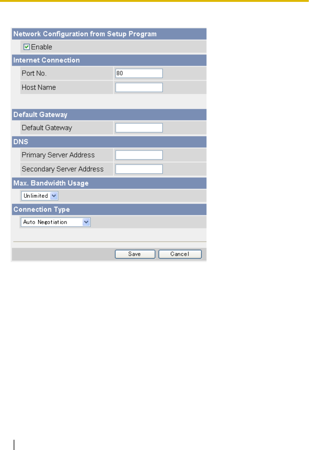
[DHCP]
1. Set the following parameters as desired.
a. Under [Network Configuration from Setup Program], select whether or not you want to allow the camera
to be configured using the Setup Program on the CD-ROM.
b. Under [Internet Connection], enter the port number to be assigned to the camera.
•The default port number is 80, however, note that some ISPs do not allow access from the Internet
using port 80. Ask your ISP or network administrator about which port numbers are available for
access over the Internet.
•Do not use the following port numbers:
–20 and 21: used for FTP
–23: used for Telnet
–25: used for SMTP
–53: used for DNS
–110: used for POP3
–443: used for HTTPS
–4000: used for ICQ
–6661–6667: used for IRC
•If you are connecting multiple cameras and plan on using port forwarding to allow Internet access
to the cameras, assign a different port number to each camera. We recommend using port numbers
in the 50000–50050 range.
c. Enter the host name*1 if required by your ISP or network administrator.
116 Operating Instructions
5.1.1 Network (IPv4) Settings

•If the camera is connected to a router, you can usually leave this field blank.
d. Under [Default Gateway], enter the default gateway IP address if required by your ISP or network
administrator.
•This field can normally be left empty.
e. Under [DNS], enter the IP addresses of the primary and secondary DNS servers if required by your
ISP or network administrator.
•These fields can normally be left empty.
f. Under [Max. Bandwidth Usage], select the maximum bandwidth you want to allow the camera to use.
•This setting is effective for both IPv4 and IPv6 connections.
•Refer to the following file size information when restricting the maximum bandwidth. Note that these
are estimated file sizes for one JPEG image (the actual file size may vary depending on image
quality, image brightness, etc.). To determine the bandwidth required, multiply this number by the
number of accesses (for JPEG images), and multiply the H.264 or MPEG-4 bit rate setting on the
[Video Streaming] page by the number of H.264 or MPEG-4 accesses.
–192 ´ 144: 7 KB (56 Kbit)
–320 ´ 240: 16 KB (128 Kbit)
–640 ´ 480: 35 KB (280 Kbit)
g. Under [Connection Type], select the appropriate connection type.
•Normally you can leave this setting at [Auto Negotiation].
•This setting is effective for both IPv4 and IPv6 connections.
2. Click [Save].
3. When the [New settings are saved.] message is displayed, click [Restart].
•All images buffered in the internal memory are deleted when the camera is restarted.
*1 [Space], ["], ['], [&], [<], and [>] cannot be entered.
Note
•If the camera’s IP address was changed as a result of changing the network settings, use the Setup
Program on the CD-ROM to find the camera’s new IP address (see Page 202).
•The current network settings can be confirmed on the [Status] page (see Page 176).
Operating Instructions 117
5.1.1 Network (IPv4) Settings
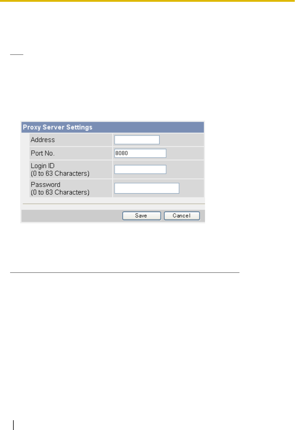
5.1.2 Proxy Server Settings
The following settings are necessary if your network uses a proxy server and you want to transfer images by
HTTP or send trigger notifications by HTTP. If you do not use a proxy server, these settings are unnecessary.
Note
•Consult your Internet Service Provider (ISP) or network administrator to find out if your network uses
a proxy server.
•The camera does not use encryption when sending the login ID and password to access the proxy
server. Use caution as necessary to prevent disclosure of this information.
•For added security, we recommend periodically changing the login ID and password that are required
to access your proxy server.
1. Click the [Setup] tab.
2. On the left side of the screen under [Basic], click [Network (IPv4)].
3. Under [Proxy Server Settings], enter the address*1 port no., login ID*2 and password*2 that are required to
access the proxy server.
•Ask your ISP or network administrator for the correct settings.
•An IPv6 address can be specified; note that the IPv6 address must be enclosed in brackets.
4. Click [Save].
*1 [Space], ["], ['], [&], [<], and [>] cannot be used.
*2 ["] cannot be used.
118 Operating Instructions
5.1.2 Proxy Server Settings
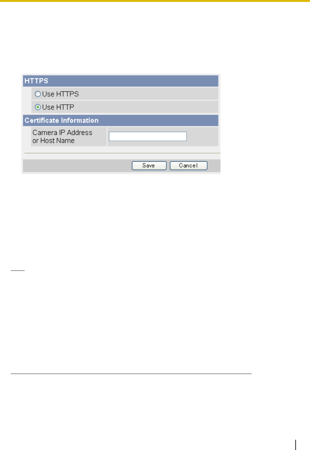
5.2 HTTPS Settings
The camera supports HTTPS connections. When accessing the camera using HTTPS, data sent between the
computer and camera is encrypted, providing increased security. To access the camera using HTTPS, see
Page 120.
1. Click the [Setup] tab.
2. On the left side of the screen under [Basic], click [HTTPS].
3. Set the following parameters as desired.
a. Under [HTTPS], select [Use HTTPS] if you want to use the HTTPS feature.
b. If [HTTPS] is set to [Use HTTPS], enter the IP address or host name of the server that contains the
SSL key under [Certificate Information].*1
•Generally the camera’s IP address can be entered here.
4. Click [Save].
•It may take up to 5 minutes to receive the SSL key. The camera cannot be accessed using HTTPS
until the SSL key is received.
5. When the [Success!] message is displayed, click [Restart].
•All images buffered in the internal memory are deleted when the camera is restarted.
Note
•When the camera is configured for HTTPS access, it cannot be accessed using HTTP. Similarly, when
the camera is configured for HTTP access (i.e., when [HTTPS] is set to [Use HTTP]), it cannot be
accessed using HTTPS.
•When configuring the camera for access from the Internet, enter the IP address or host name used to
access the camera over the Internet next to [Camera IP Address or Host Name]. In this case a security
warning will be displayed when accessing the camera over the local network.
•When accessing the camera using HTTPS, the following may occur.
–Frame rate may decrease and camera response time may increase.
–It may take a while to display images.
–Images may break up or audio may be interrupted at the beginning of the access.
•BL-C210A/BL-C230A only: If [HTTPS] is set to [Use HTTPS], the camera cannot be accessed from
a TV and you cannot set the camera to registration mode (see Page 172).
*1 [Space], ["], ['], [&], [<], and [>] cannot be entered.
Operating Instructions 119
5.2 HTTPS Settings

Accessing the camera using HTTPS
If the camera is configured for HTTPS access, it can only be accessed using HTTPS; HTTP access is not
possible. Use the following address format when accessing the camera using HTTPS.
1. Start your PC’s web browser.
2. In the browser’s address bar, enter https:// followed by the IP address or host name and the port number
of the camera, then press [Enter] on the keyboard.
Example: https://192.168.0.253:80
•If you have registered with a Dynamic DNS service, such as Viewnetcam.com (see Page 105), enter
the URL instead of the IP address. Note that accessing the camera this way may only work when you
are accessing the camera from outside, i.e., from a PC that is not connected to the same network as
the camera.
Example: https://***.viewnetcam.com:80
3. When the authentication dialog is displayed, enter the user name and password, then click [OK]. The top
page is displayed.
Note
•If the authentication dialog is not displayed, click the [Login] tab after the camera’s top page is
displayed. For more information, see Page 158.
Installing security certificates
When accessing the camera using HTTPS, a security warning is displayed if there is a security certificate that
corresponds to the camera is not installed on the PC. To prevent this dialog from being displayed, follow the
procedure below and install a security certificate.
Note
•The value entered next to [Camera IP Address or Host Name] on the [HTTPS] screen must match the
IP address or host name used to access the camera. If this value does not match, a security warning
will be displayed when accessing the camera.
•If the IP address or host name used to access the camera changes after installing the security
certificate, a security warning will be displayed when accessing the camera. To prevent the security
warning from being displayed, a new security certificate must be installed.
•When configuring the camera for access from the Internet, enter the IP address or host name used to
access the camera over the Internet next to [Camera IP Address or Host Name]. In this case a security
warning will be displayed when accessing the camera over the local network.
For Internet Explorer 7/Internet Explorer 8 and Windows Vista/Windows XP
Note
•Screens displayed when using Windows XP vary slightly from those shown below.
1. Access the camera using HTTPS.
2. When the security warning is displayed, click [Continue to this website (not recommended).].
120 Operating Instructions
5.2 HTTPS Settings
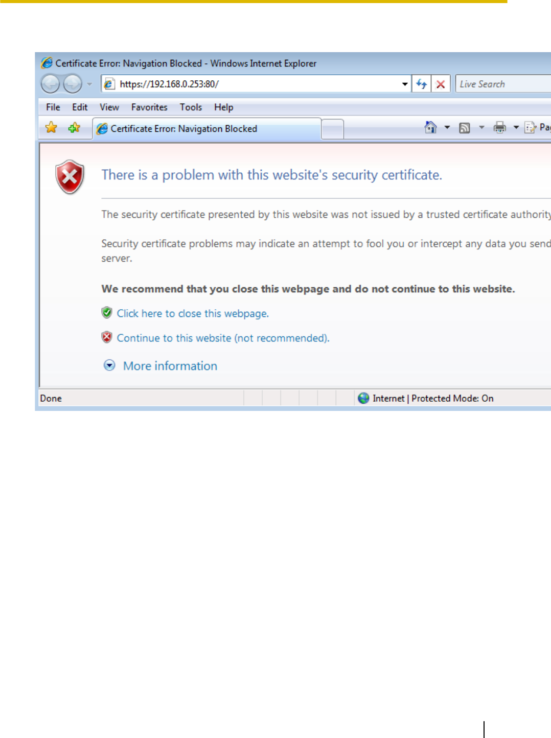
•Installing security certificates for unknown devices or sites can lead to security risks. Confirm the origin
of the security certificates before installing them for devices or sites other than the camera.
3. When the authentication dialog is displayed, enter the user name and password, then click [OK].
•The top page is displayed.
Operating Instructions 121
5.2 HTTPS Settings
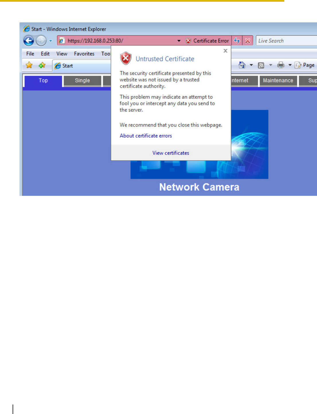
4. Click [Certificate Error] in the address bar, then click [View certificates].
122 Operating Instructions
5.2 HTTPS Settings
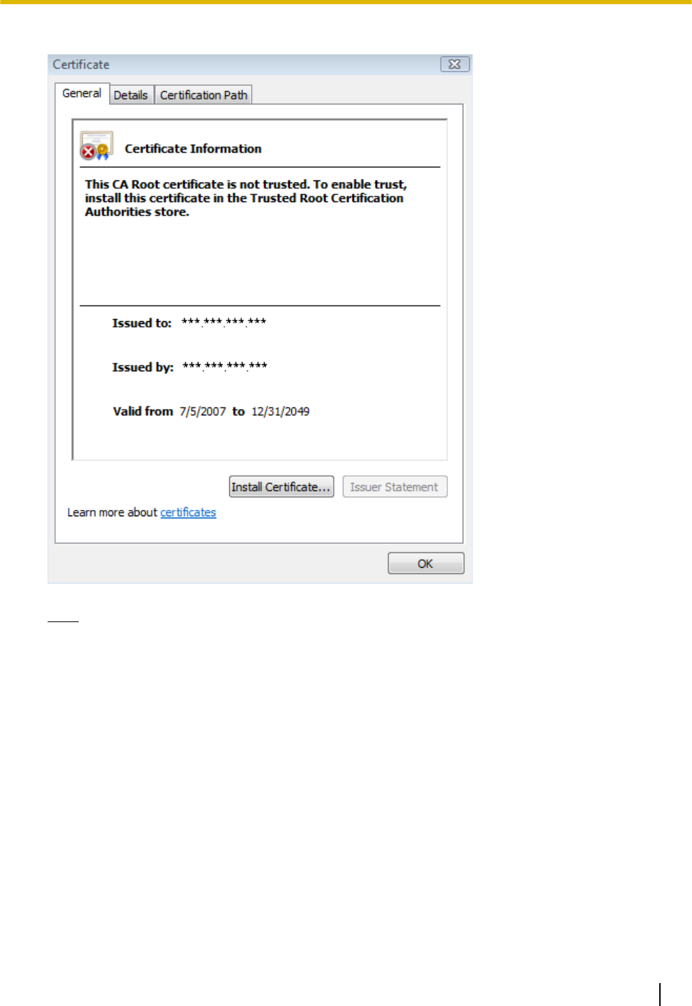
5. Click [Install Certificate...].
Note
•If the [Install Certificate...] button is not displayed, exit Internet Explorer, then start Internet Explorer
using the [Run as administrator] option. Click [Start]®[All Programs]®right-click [Internet
Explorer], then click [Run as administrator].
Operating Instructions 123
5.2 HTTPS Settings
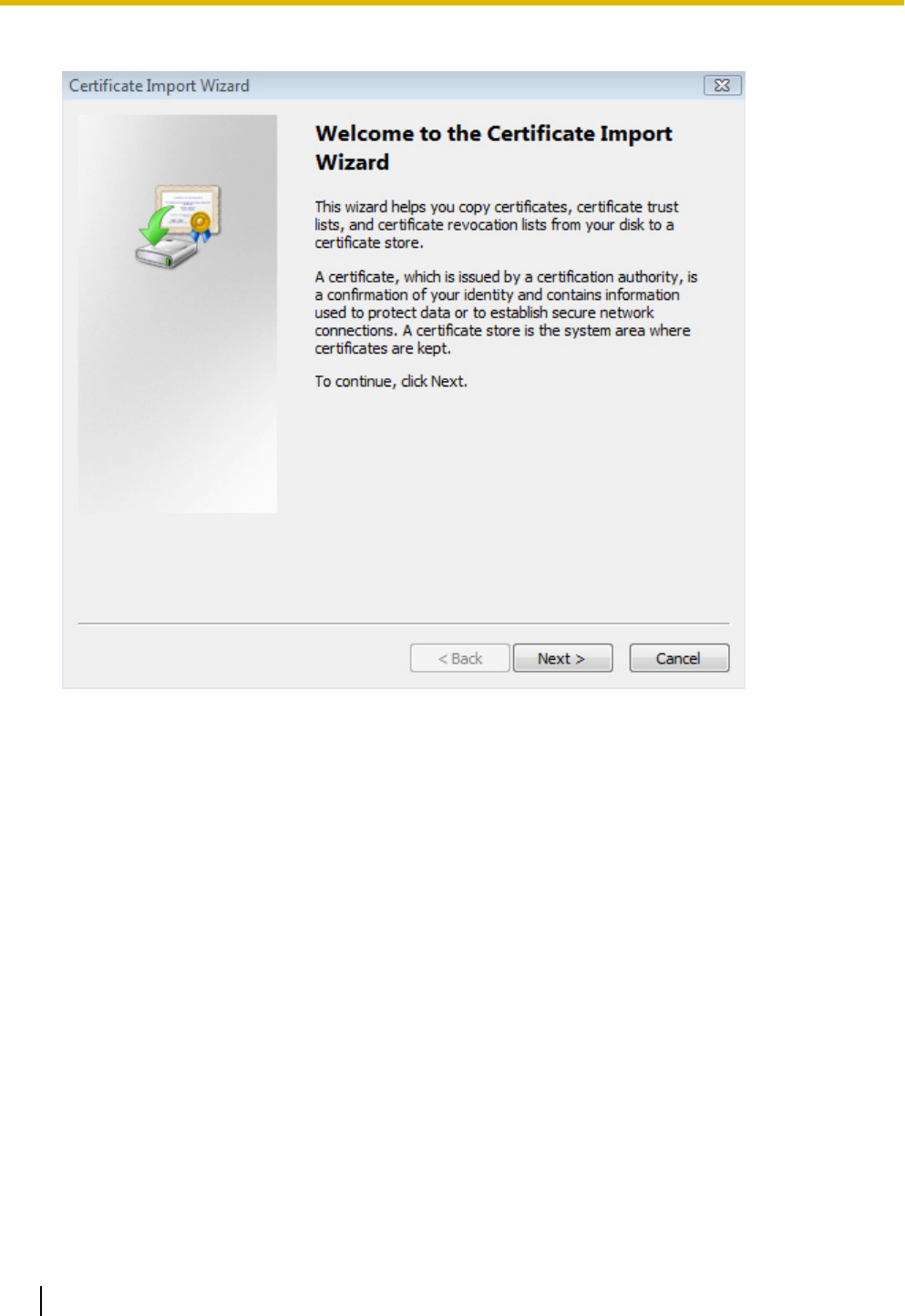
6. After the wizard is displayed, click [Next].
124 Operating Instructions
5.2 HTTPS Settings
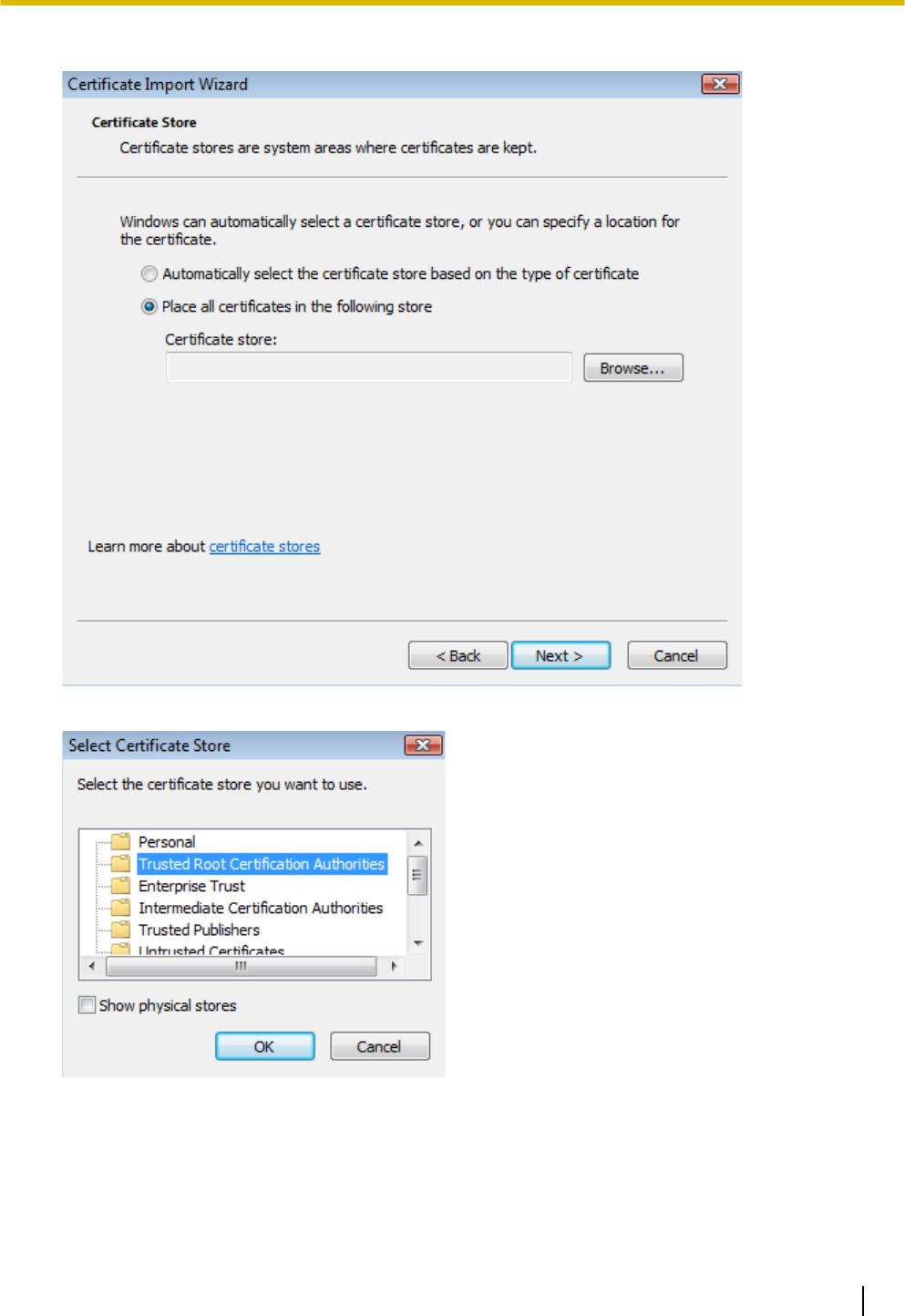
7. Select [Place all certificates in the following store], then click [Browse...].
8. Click [Trusted Root Certification Authorities], then click [OK].
Operating Instructions 125
5.2 HTTPS Settings
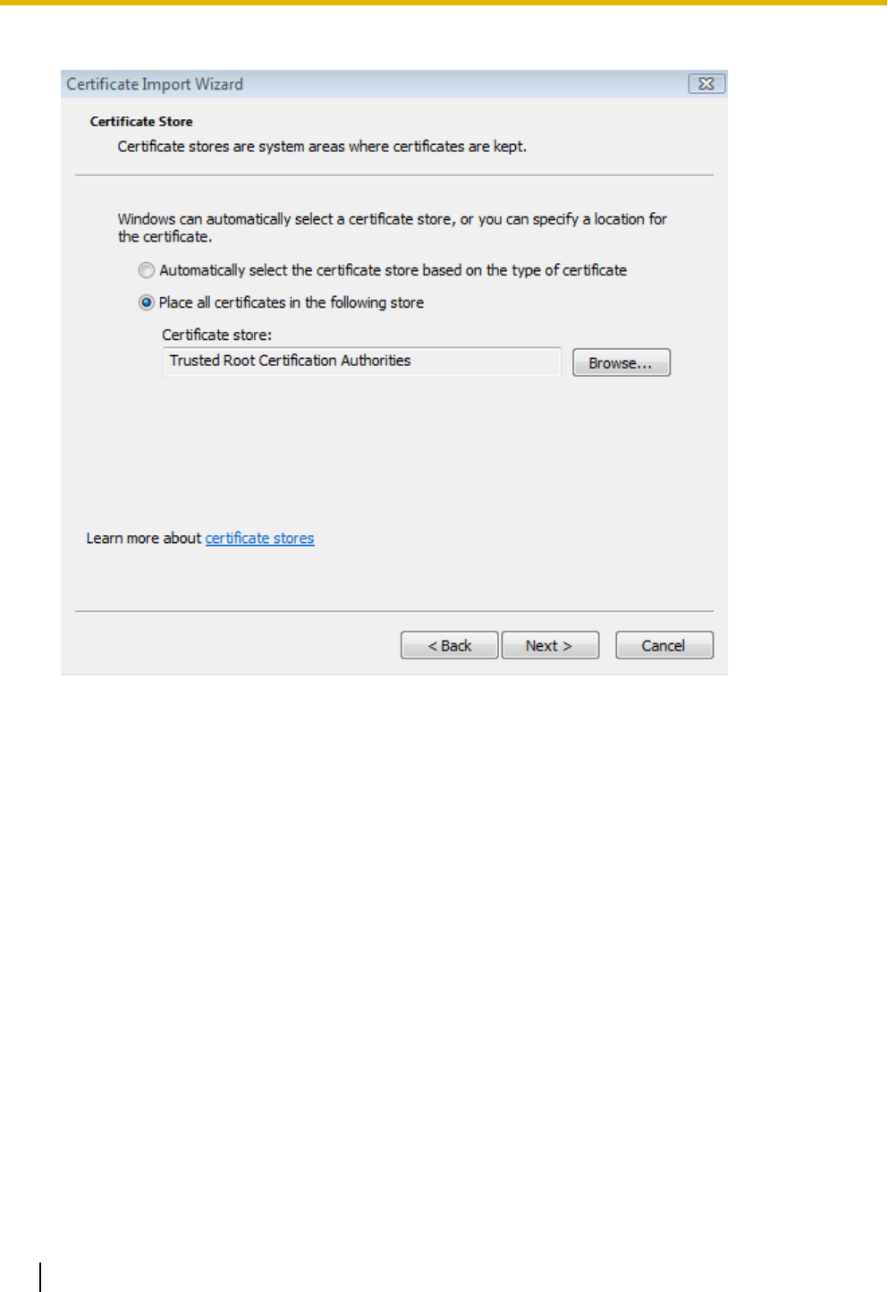
9. Click [Next].
126 Operating Instructions
5.2 HTTPS Settings
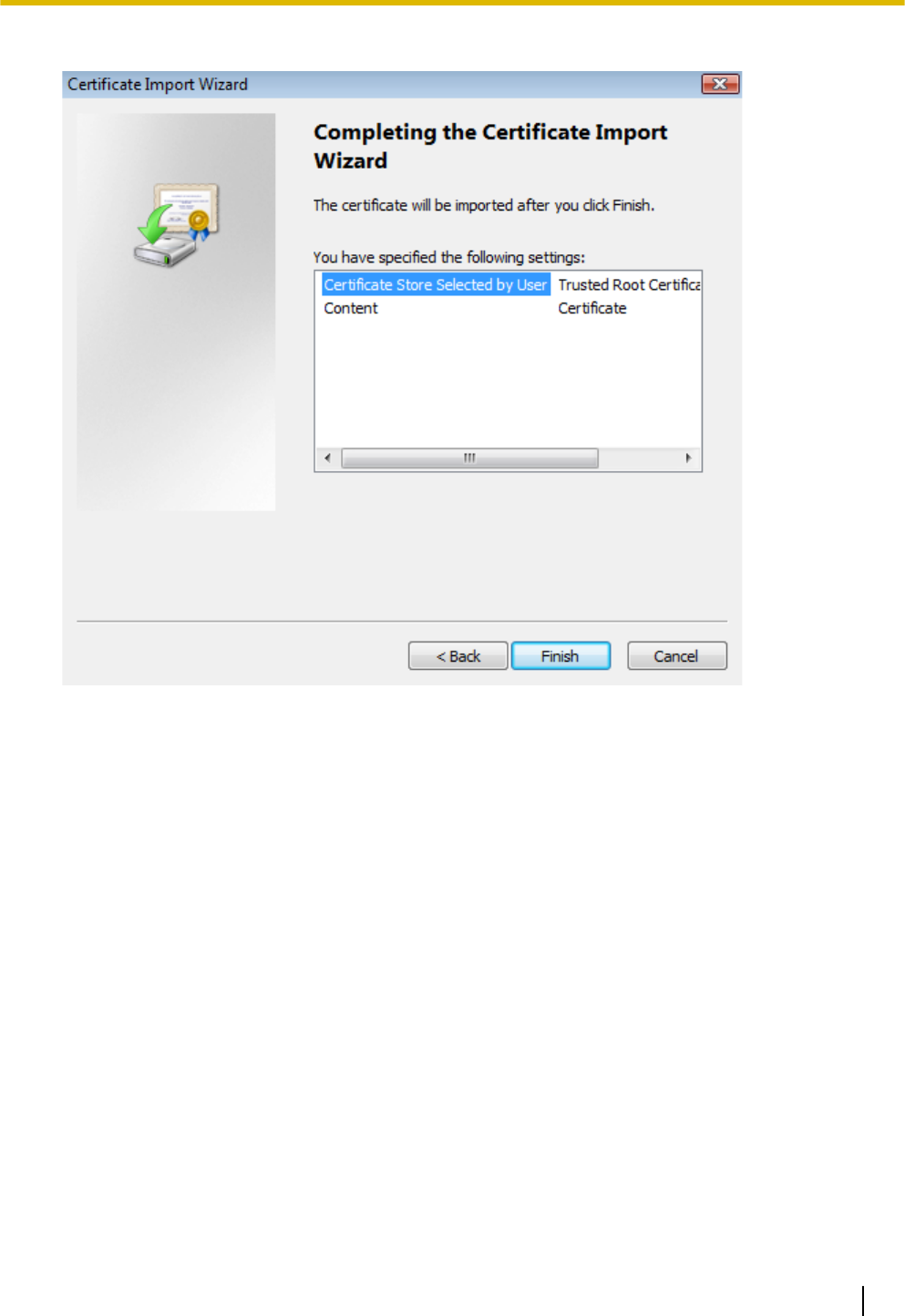
10. Click [Finish].
Operating Instructions 127
5.2 HTTPS Settings
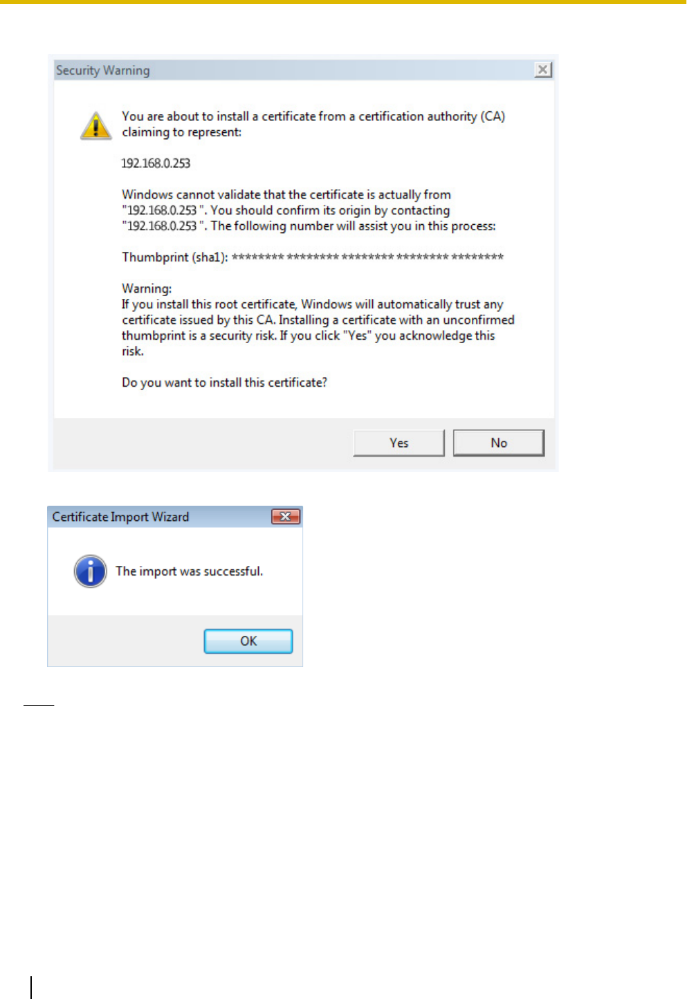
11. Click [Yes].
12. After [The import was successful.] is displayed, click [OK].
Note
•After you restart the browser and access the camera using HTTPS, the security warning will not be
displayed.
For Internet Explorer 6 and Windows XP
1. Access the camera using HTTPS.
2. Click [View Certificate].
128 Operating Instructions
5.2 HTTPS Settings
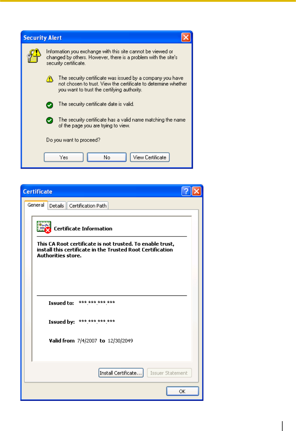
•Installing security certificates for unknown devices or sites can lead to security risks. Confirm the origin
of the security certificates before installing them for devices or sites other than the camera.
3. Click [Install Certificate...].
Operating Instructions 129
5.2 HTTPS Settings
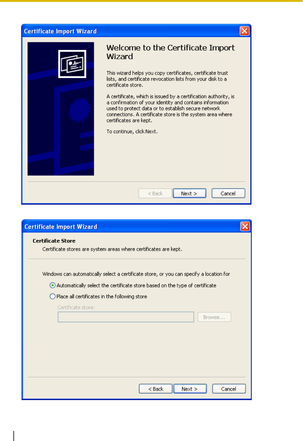
4. After the wizard is displayed, click [Next].
5. Select [Automatically select the certificate store based on the type of certificate], then click [Next].
130 Operating Instructions
5.2 HTTPS Settings
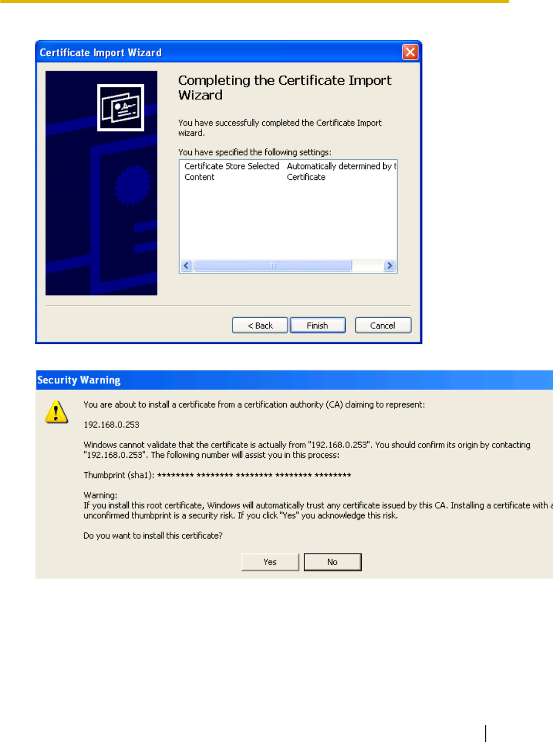
6. Click [Finish].
7. Click [Yes].
Operating Instructions 131
5.2 HTTPS Settings

8. After [The import was successful.] is displayed, click [OK].
Note
•After you restart the browser and access the camera using HTTPS, the security warning will not be
displayed.
132 Operating Instructions
5.2 HTTPS Settings

5.3 Using the Camera in Wireless Mode (BL-C230
Only)
The BL-C230 can be used wirelessly. In this case, there is no need to connect a LAN cable to the camera.
In order to use the camera wirelessly, you must:
1. Configure the camera for wired connection. Refer to the included Installation Guide and Setup Guide if you
have not done this.
2. Configure the camera’s wireless settings (see Page 134).
3. Restart the camera in wireless mode (see Page 138).
Note
•If images cannot be displayed or if images break up, the following devices may be causing interference.
–wireless LAN devices
–2.4 GHz cordless telephones/faxes
–microwave ovens
–wireless AV devices
If the above devices are causing interference, change the wireless communication channels of the
camera and the router not to overlap with interfering devices. For more information, refer to the
operating instructions included with your wireless router.
•If communicating to another wireless device (a PC, etc.) using the wireless router that the camera is
connected, streaming may become congested because the wireless bandwidth is shared.
Operating Instructions 133
5.3 Using the Camera in Wireless Mode (BL-C230 Only)
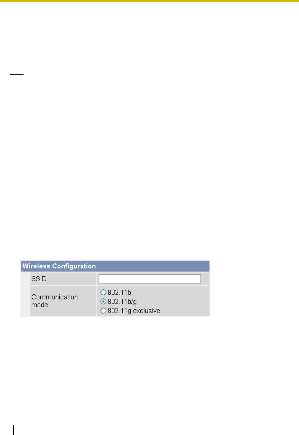
5.3.1 Configuring the Camera for Wireless Connection (BL-C230
Only)
Configure the camera for wireless access by configuring the corresponding camera settings to match the
wireless settings of your wireless router. For more information, refer to the operating instructions included
with your wireless router.
Note
•SSID is an identification name that is used to distinguish and separate wireless connections into groups.
It is also called Network Name (SSID), Wireless network name (SSID), or ESSID.
Cipher is a technology that increases security in wireless communications by using encryption methods
(WEP, WPA-PSK (TKIP), or WPA2-PSK (AES)) to encrypt data sent on the network. It is also called
Security or Security Mode.
•WPA-PSK (TKIP) and WPA2-PSK (AES) have stronger encryption than WEP and have high level
security capabilities. We recommend using WPA-PSK (TKIP) or WPA2-PSK (AES) as the encryption
method.
•Encryption helps protect wireless communications from being accessed or intercepted by unauthorized
parties. Using the encryption features on your wireless router and the camera is recommended.
•If your wireless router uses MAC address filtering, enter the MAC address of the camera and the MAC
address of the camera’s wireless module when setting your wireless router’s MAC address filtering
feature. You can confirm the camera’s MAC address on the [Status] page (see Page 176) and the
MAC address of the wireless module on the [Wireless Status] page (see Page 177).
•After changing and saving the camera’s wireless settings, it takes about 1 minute for the new settings
to become effective.
•Even if the camera is turned on in wired mode, it emits radio waves for about 5 minutes. During this
time, the router’s wireless indicator may light or flash.
•To switch between wired and wireless connection (see Page 138), the camera must be restarted. Your
router may also need to be restarted before the camera can access the router.
•If communicating to another wireless device (a PC, etc.) using the wireless router that the camera is
connected, streaming may become congested because the wireless bandwidth is shared.
1. Click the [Setup] tab.
2. On the left side of the screen under [Basic], click [Wireless].
3. Under [Wireless Configuration], enter the SSID used by your wireless router (max. 32 characters).
4. Select the wireless standard used by your wireless router.
•Even if your router supports the 802.11g standard (which is theoretically faster than 802.11b), wireless
communication speed may decrease if there are other devices nearby which use the 2.4 GHz
bandwidth, including devices that use the 802.11b standard.
5. Under [Encryption], select the desired encryption method, make the appropriate settings (explained below),
then click [Save].
134 Operating Instructions
5.3.1 Configuring the Camera for Wireless Connection (BL-C230 Only)
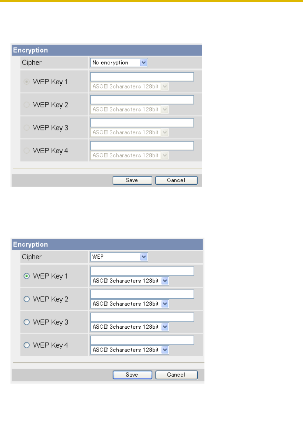
When [No encryption] is selected
When [No encryption] is selected, encryption will not be used for wireless communications, and therefore
wireless communication may not be secure. If you select [No encryption], click [Save] to finish.
When [WEP] is selected
When [WEP] is selected, the WEP standard will be used for encryption. Refer to the settings of your wireless
router, then select the WEP key (1–4) used by your wireless router, select the key format from the
corresponding pull-down menu, enter the WEP key, then click [Save] to finish.
Operating Instructions 135
5.3.1 Configuring the Camera for Wireless Connection (BL-C230 Only)
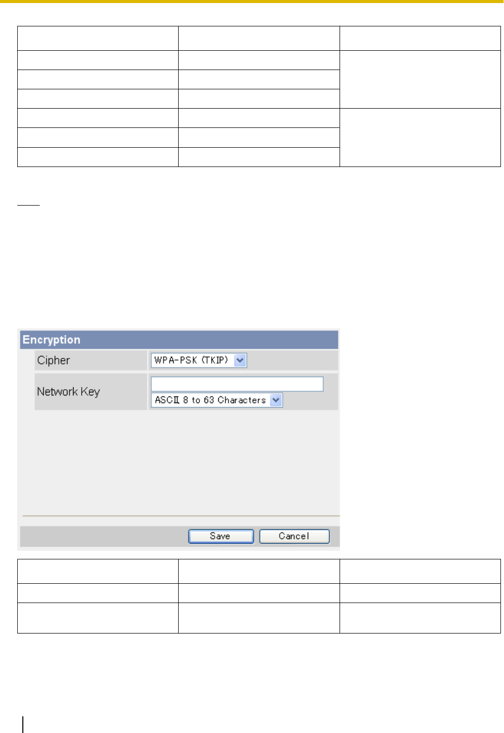
Key Format No. of Characters Usable Characters
[HEX,10characters 64bit] 10
0–9, a–f
[HEX,26characters 128bit] 26
[HEX,32characters 152bit] 32
[ASCII 5characters 64bit] 5
ASCII characters (see
Page 206)*1
[ASCII13characters 128bit] 13
[ASCII16characters 152bit] 16
*1 [Space] cannot be used.
Note
•The camera supports only open system authentication. If the wireless router or access point is
configured to use shared key authentication, reconfigure the wireless router or access point to use auto
or open system authentication.
When [WPA-PSK (TKIP)] is selected
When [WPA-PSK (TKIP)] is selected, the WPA-PSK (TKIP) standard will be used for encryption. Refer to the
settings of your wireless router, then enter the [Network Key], select the key format from the pull-down
menu, and click [Save] to finish.
Key Format No. of Characters Usable Characters
[HEX, 64 Characters] 64 0–9, a–f
[ASCII, 8 to 63 Characters] 8–63 ASCII characters (see
Page 206)*1
*1 [Space] cannot be used.
136 Operating Instructions
5.3.1 Configuring the Camera for Wireless Connection (BL-C230 Only)
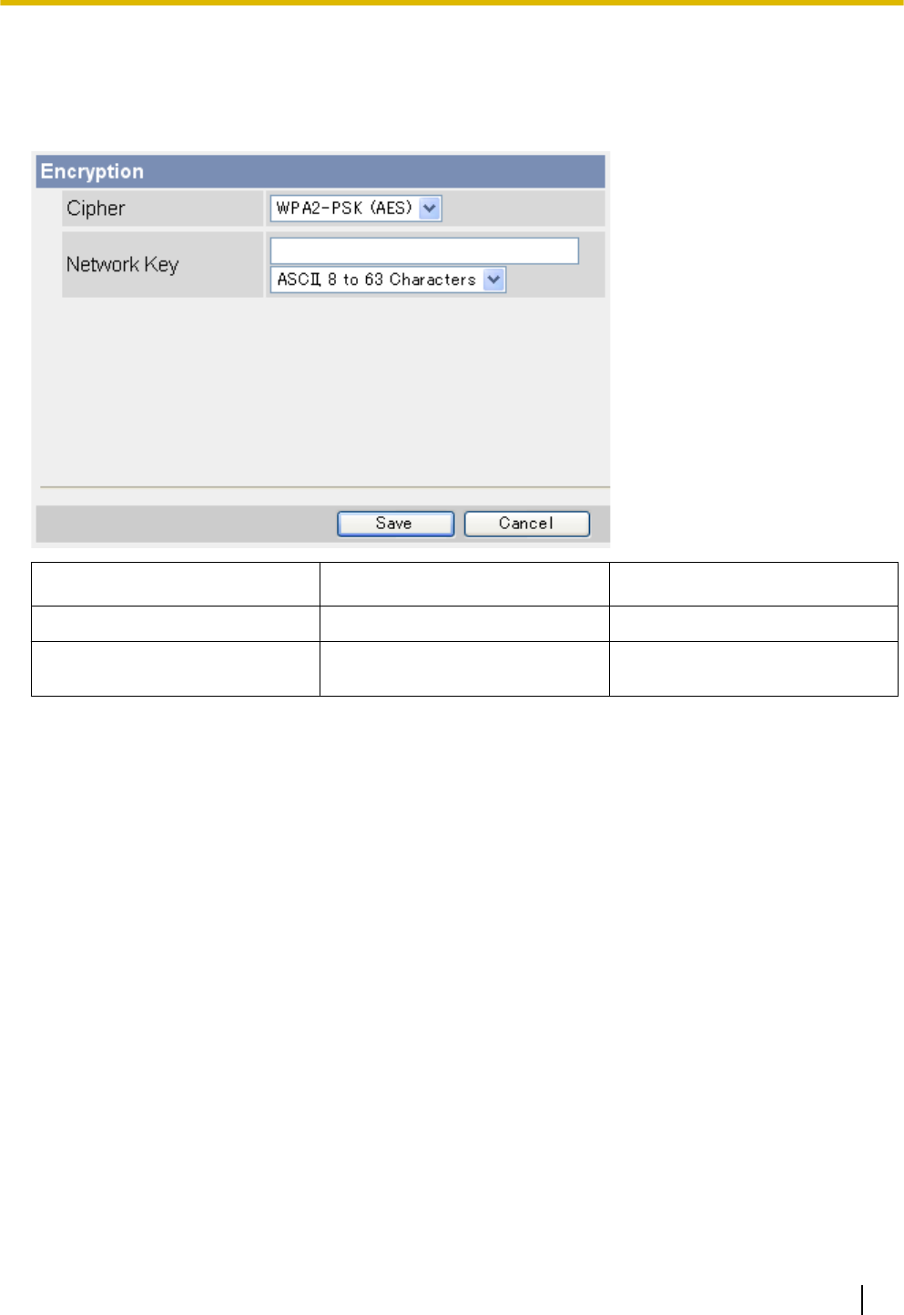
When [WPA2-PSK (AES)] is selected
When [WPA2-PSK (AES)] is selected, the WPA2-PSK (AES) standard will be used for encryption. Refer to
the settings of your wireless router, then enter the [Network Key], select the key format from the pull-down
menu, and click [Save] to finish.
Key Format No. of Characters Usable Characters
[HEX, 64 Characters] 64 0–9, a–f
[ASCII, 8 to 63 Characters] 8–63 ASCII characters (see
Page 206)*1
*1 [Space] cannot be used.
Operating Instructions 137
5.3.1 Configuring the Camera for Wireless Connection (BL-C230 Only)

5.3.2 Restarting the Camera in Wireless Mode (BL-C230 Only)
After you have configured the camera for wireless connection, follow the procedure below to restart the camera
in wireless mode.
1. Turn off the camera by unplugging the AC plug from the power outlet.
2. Set the WIRELESS/WIRED switch on the bottom of the camera to the WIRELESS position.
3. Turn the camera on by plugging the AC plug into the power outlet.
4. Confirm the camera’s wireless settings are correct by accessing the camera (see Page 8).
Note
•To use the camera in wired mode again, repeat the procedure above and set the WIRELESS/
WIRED switch on the bottom of the camera to the WIRED position.
•If you cannot access the camera, the camera’s wireless settings may be incorrect. Repeat the
procedure above and set the WIRELESS/WIRED switch on the bottom of the camera to the WIRED
position. Access the camera in wired mode and confirm that all wireless settings are correct and match
the settings of your wireless router.
•If your wireless router uses MAC address filtering, enter the MAC address of the camera and the MAC
address of the camera’s wireless module when setting your wireless router’s MAC address filtering
feature. You can confirm the camera’s MAC address on the [Status] page (see Page 176) and the
MAC address of the wireless module on the [Wireless Status] page (see Page 177).
•You may need to restart your router in order to access the camera in wireless mode.
•Even if the camera is turned on in wired mode, it emits radio waves for about 5 minutes. During this
time, the router’s wireless indicator may light or flash.
•If you still cannot access the camera in wireless mode, see 1.4 Wireless Connection Issues (BL-C230
Only) in the Troubleshooting Guide.
138 Operating Instructions
5.3.2 Restarting the Camera in Wireless Mode (BL-C230 Only)
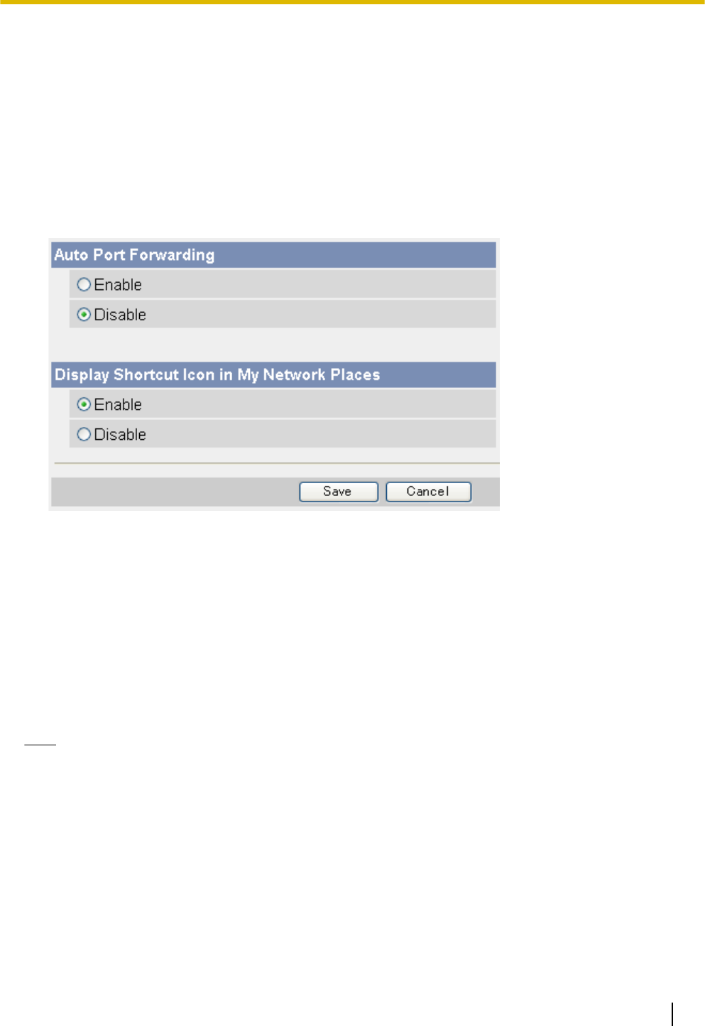
5.4 UPnP™ Settings
The camera supports UPnP™ (Universal Plug and Play) features, which allow you to do the following:
–Configure your router’s port forwarding feature. (A UPnP™ compatible router is required.) This is useful if
you want to access your camera from the Internet or using a mobile phone. See Page 96 for more
information.
–BL-C210CE/BL-C210E/BL-C230CE/BL-C230E only: Create a shortcut to the camera in your
computer’s [My Network Places] folder ([Network] folder when using Windows Vista) that will be
automatically updated even if the camera’s IP address changes.
1. Click the [Setup] tab.
2. On the left side of the screen under [Basic], click [UPnP].
3. Set the following parameters as desired.
a. Under [Auto Port Forwarding], select [Enable] if you want to configure your router’s port forwarding
feature.
•In order to use this feature, your router must support UPnP™ and have its UPnP™ feature turned
on.
b. BL-C210CE/BL-C210E/BL-C230CE/BL-C230E only: Under [Display Shortcut Icon in My Network
Places], select [Enable] if you want to create a shortcut to the camera in your computer’s [My Network
Places] folder ([Network] folder when using Windows Vista).
•In order to use this feature, your computer’s UPnP™ feature must be enabled. See Page 198 for
more information.
4. Click [Save].
Note
•You can also configure your UPnP™ compatible router for port forwarding from the [Internet] tab (see
Page 100).
•Screen content varies by model number.
•BL-C210A/BL-C230A only: [Display Shortcut Icon in My Network Places] is not displayed. This feature
is enabled for the camera and cannot be changed.
Operating Instructions 139
5.4 UPnP™ Settings
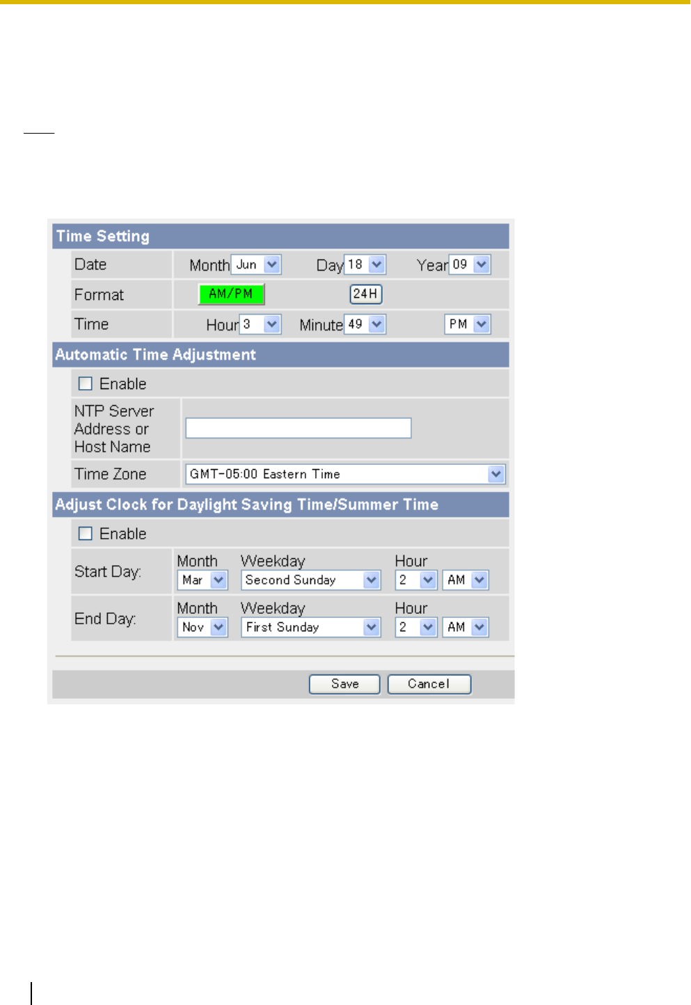
5.5 Setting the Date and Time
Set the camera’s date and time settings to ensure image buffering, image transferring, camera operation time,
and time stamp features function as expected.
Note
•All images buffered in the internal memory are deleted when you click [Save] at the end of this
procedure.
1. Click the [Setup] tab.
2. On the left side of the screen under [Basic], click [Date and Time].
3. Set the following parameters as desired.
a. Under [Time Setting], select the current month, day, and year.
b. Select whether you want to use 12-hour or 24-hour time format.
c. Select the current time.
d. Under [Automatic Time Adjustment], select whether you want to enable automatic date and time
adjustment.
i.
If you select to enable this feature, enter the IP address or host name of the desired NTP (network
time protocol) server*1 (max. 255 characters) that the camera will use to adjust its date and time.
•An IPv6 address can be specified; note that the IPv6 address must be enclosed in brackets.
ii.
Select your time zone.
e. Under [Adjust Clock for Daylight Saving Time/Summer Time], select whether you want the camera to
automatically adjust its date and time for Daylight Saving Time/Summer Time.
140 Operating Instructions
5.5 Setting the Date and Time

i.
If you select to enable this feature, enter the month, day, and time when Daylight Saving Time/
Summer Time begins. (The camera’s clock moves forward one hour at the set date and time.)
ii.
Enter the month, day, and time when Daylight Saving Time/Summer Time ends. (The camera’s
clock moves back one hour at the set date and time.)
4. Click [Save].
•All images buffered in the internal memory are deleted when you click [Save].
*1 [Space], ["], ['], [&], [<], and [>] cannot be entered.
Note
•The camera will not synchronize to the NTP server if there is more than an 1 hour difference between
the NTP server time and the camera’s current time. This is to protect the camera’s time setting from
fraudulent NTP server tampering, incorrect time information, etc.
•The camera’s clock becomes less accurate over time and can be affected when the camera’s
temperature changes. Using the [Automatic Time Adjustment] feature is recommended.
•Screen content varies by model number.
Operating Instructions 141
5.5 Setting the Date and Time
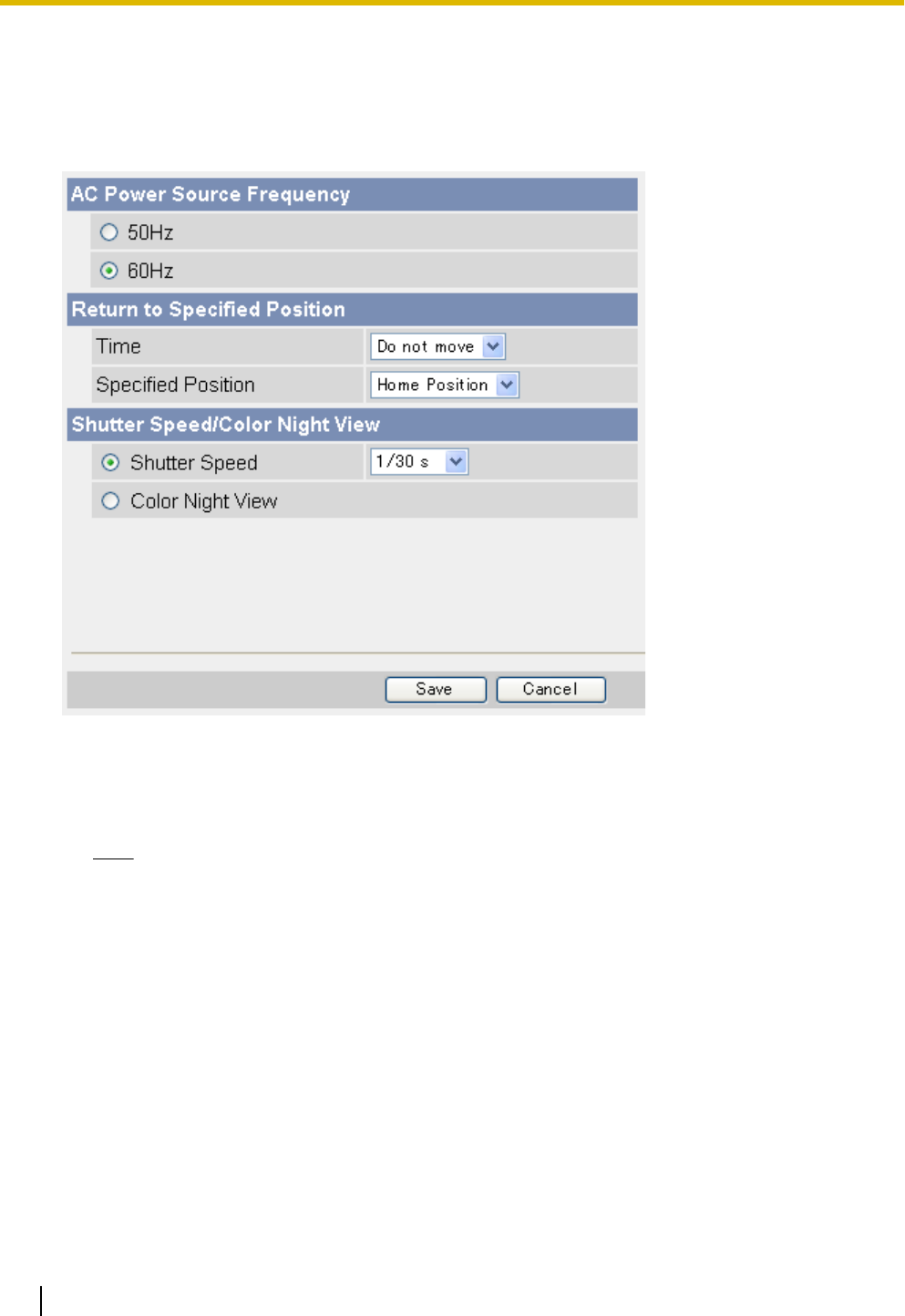
5.6 Changing Basic Camera Settings
The [Camera] page of the [Setup] tab allows you to adjust basic camera features.
1. Click the [Setup] tab.
2. On the left side of the screen under [Basic], click [Camera].
3. Set the following parameters as desired.
a. Under [AC Power Source Frequency], select the desired setting.
–[50 Hz]: Select this item if your AC power source operates at 50 Hz.
–[60 Hz]: Select this item if your AC power source operates at 60 Hz.
Note
•Screen content varies by model number.
b. Under [Return to Specified Position], select whether you want the camera to move the lens to a specific
preset position after a specified period of inactivity.
i.
Select the length of time (inactivity) that passes before the camera moves the lens. If this setting
is too short, you may have difficulty registering presets because the lens will return to the specified
position before you have saved your new preset.
ii.
Select the desired preset position (see Page 29).
c. Under [Shutter Speed/Color Night View], select whether the camera’s shutter speed is fixed, or whether
the color night view mode feature automatically adjusts the shutter speed when the camera image is
dark.
i.
To set the shutter speed, select [Shutter Speed], then select the desired speed from the pull-down
menu.
•The available shutter speeds depend on the [AC Power Source Frequency] setting, as follows:
50 Hz: 1/25 s, 1/50 s, 1/100 s
60 Hz: 1/30 s, 1/60 s, 1/120 s
142 Operating Instructions
5.6 Changing Basic Camera Settings

•This setting determines the minimum shutter speed. Shutter speed may increase when viewing
bright objects.
•Note that when the shutter speed is faster, noise may be seen in the camera image depending
on the light source, and noise may increase depending on the brightness of the image.
ii.
To enable the color night view mode feature, select [Color Night View]. (Page 210)
•When the camera image becomes dark (e.g., when the lights in a room are turned off), the
shutter speed is reduced.
•This feature is disabled by default.
•Note that when this feature is activated:
–Refresh rate decreases and images become blurry when the object is moving.
–White or colored dots or horizontal lines may be displayed in the camera image. This is a
characteristic of the camera’s image sensor, and is not a malfunction.
4. Click [Save].
Operating Instructions 143
5.6 Changing Basic Camera Settings
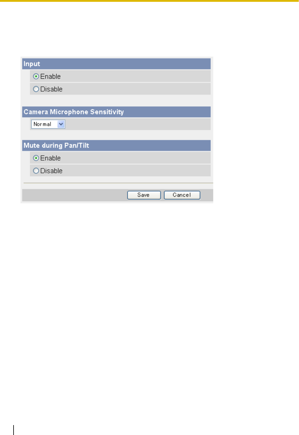
5.7 Changing Audio Settings
The [Audio] page of the [Setup] tab allows you to adjust audio feature-related settings.
1. Click the [Setup] tab.
2. On the left side of the screen under [Basic], click [Audio].
3. Set the following parameters as desired.
a. Under [Input], select whether the camera’s microphone is enabled or disabled.
•When set to [Disable], the sound detection feature is not available.
b. Under [Camera Microphone Sensitivity], select the desired setting.
–[Very Low]: Sets the microphone to very low sensitivity. Further less sound is picked up by the
microphone.
–[Low]: Sets the microphone to low sensitivity. Less sound is picked up by the microphone.
–[Normal]: Sets the microphone to moderate sensitivity.
–[High]: Sets the microphone to high sensitivity. More sound is picked up by the microphone.
•This setting affects the performance of the sound detection feature. After changing this setting,
adjust sound detection sensitivity again (see Page 84).
c. Under [Mute during Pan/Tilt], select whether the camera’s microphone is automatically muted when
the camera is panning or tilting.
•This feature is enabled by default.
•When this feature is set to [Disable], the microphone will be enabled when the camera pans or tilts.
The sound of the lens moving may be picked up by the microphone.
4. Click [Save].
144 Operating Instructions
5.7 Changing Audio Settings

5.8 Changing Video Streaming Settings
The [Video Streaming] page of the [Setup] tab allows you to adjust video streaming feature-related settings.
1. Click the [Setup] tab.
Operating Instructions 145
5.8 Changing Video Streaming Settings
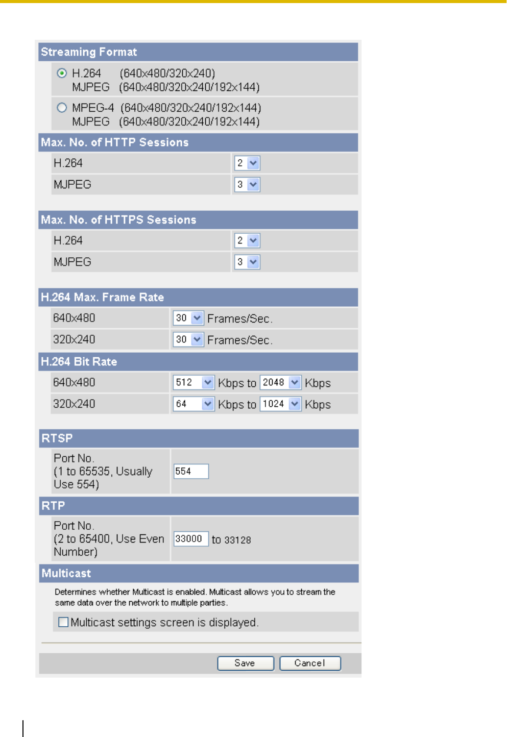
2. On the left side of the screen under [Basic], click [Video Streaming].
146 Operating Instructions
5.8 Changing Video Streaming Settings

3. Set the following parameters as desired.
a. Under [Streaming Format], select the streaming format.
•This setting may change the values selected for the [Refresh Rate] and [Image Resolution]
parameters for [Single Camera] and [Multi-Camera] on the [Image Display] page.
•Certain features are unavailable depending on this setting. See 13.5 Feature Limitations Based
on Image Format for details.
b. Under [Max. No. of HTTP Sessions], select the maximum number of HTTP sessions allowed.
•See 1.4 Maximum Number of Viewing Sessions for details.
c. Under [Max. No. of HTTPS Sessions], select the maximum number of HTTPS sessions allowed.
•See 1.4 Maximum Number of Viewing Sessions for details.
d. Under [H.264 Max. Frame Rate] or [MPEG-4 Max. Frame Rate], select the number of frames per
second the camera streams for each resolution setting.
e. Under [H.264 Bit Rate] or [MPEG-4 Bit Rate], select the minimum and maximum bit rate for each
resolution setting.
•This setting is for video only; it does not affect audio bit rate.
•The bit rates specified here are used generally for images in which only small areas of the image
change from frame to frame (for example, when the subject is not moving, when the camera is not
panning or tilting, etc.). As more of the visible area changes (for example, when the subject is
moving, when the camera is panning or tilting, etc.), a higher bit rate is used, and the actual bit rate
used may exceed the limits specified here.
•To limit the bandwidth used by the camera, adjust the [Max. Bandwidth Usage] setting of the
[IPv4] or [IPv6] pages (see Page 113 or Page 190).
f. Under [RTSP], enter the port number used for RTSP. (Usually port number 554 is used.)
g. Under [RTP], enter the first port number used for RTP. This port number must be an even number.
•The port number above RTP is used for RTCP. For example, when port number 33000 is used for
RTP, port number 33001 is used for RTCP.
h. Under [Multicast], check [Multicast settings screen is displayed.] to configure the camera for
multicasting, otherwise click [Save] to finish.
Operating Instructions 147
5.8 Changing Video Streaming Settings
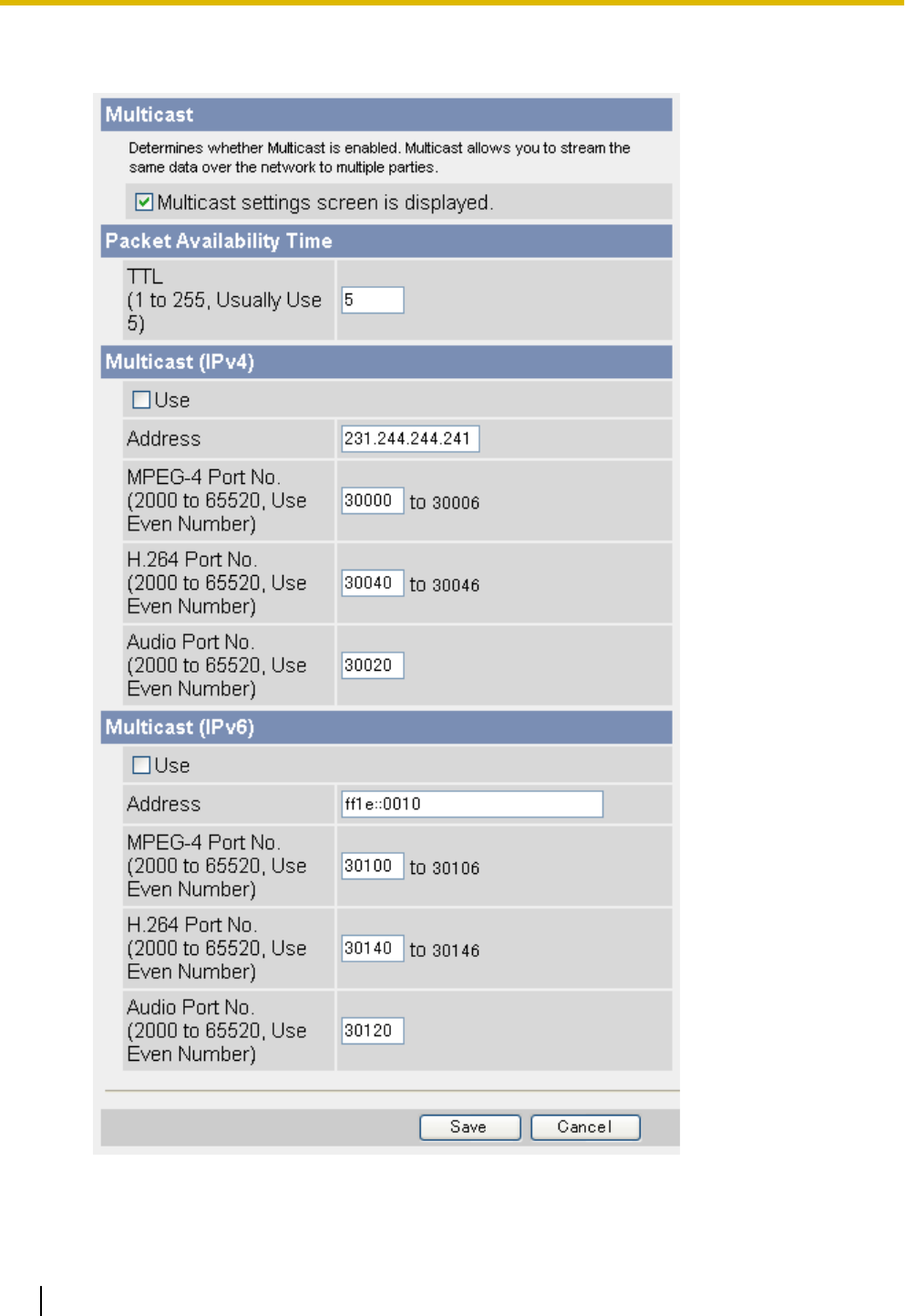
•When [Use] is checked under [Multicast (IPv4)] or [Multicast (IPv6)], [Multicast] becomes available
in the [Streaming Method] selector on the single camera page.
4. Set the following parameters as desired.
a. Under [Packet Availability Time], enter the desired setting.
148 Operating Instructions
5.8 Changing Video Streaming Settings

b. Under [Multicast (IPv4)], check [Use] to enable multicasting for IPv4. If used, the following settings are
also necessary.
i.
Enter the IP address of the multicast.
ii.
Enter the first port number to be used for MPEG-4 streaming (video only; audio is streamed on the
audio port specified on this page). This port number must be an even number.
iii.
Enter the first port number to be used for H.264 streaming. This port number must be an even
number.
iv.
Enter the port number to be used for audio streaming. This port number must be an even number.
c. Under [Multicast (IPv6)], check [Use] to enable multicasting for IPv6. If used, the following settings are
also necessary.
i.
Enter the IP address of the multicast. This address must be an IPv6 address.
ii.
Enter the first port number to be used for MPEG-4 streaming (video only; audio is streamed on the
audio port specified on this page). This port number must be an even number.
iii.
Enter the first port number to be used for H.264 streaming. This port number must be an even
number.
iv.
Enter the port number to be used for audio streaming. This port number must be an even number.
5. Click [Save].
•When any of the following settings are changed, the camera must be restarted before the new setting
takes effect. All images buffered in the internal memory are deleted when the camera is restarted.
–[Streaming Format]
–[Max. No. of HTTP Sessions]
–[Max. No. of HTTPS Sessions]
Note
•Streaming H.264 or MPEG-4 video by multicast may increase the traffic on your network. Consult your
network administrator before enabling this feature.
•If video streaming settings are saved while users are viewing H.264 or MPEG-4 images, the video
stream may stop. Users can start the stream again by clicking the refresh button in their web browsers.
•To increase image quality when streaming H.264 or MPEG-4 images, decrease the frame rate.
•To increase the frame rate, increase the setting for minimum bit rate.
•If H.264 or MPEG-4 images are unstable, reduce the setting for maximum bit rate and set the streaming
method to HTTP.
•If the network has little bandwidth or if H.264 or MPEG-4 images break up, set the streaming method
to HTTP.
•In order to stream H.264 or MPEG-4 images using unicast over the Internet, the port numbers used
by RTP must be configured for the port forwarding feature of your router. If images cannot be displayed
or if images break up when [Unicast] is selected as the streaming method, select [HTTP].
•Screen content varies by model number.
•BL-C230 only: When in wireless mode, Multicast may not work properly because the IEEE 802.11
standard limits the bandwidth. Select [Unicast] or [HTTP] as the streaming method.
Operating Instructions 149
5.8 Changing Video Streaming Settings

6 User Accounts
6.1 Understanding User Accounts
The camera supports 3 different types of users. Each type of user can use the camera in different ways, and
the administrator can control which features each user can have access to.
User Type No. of Users Camera Configuration Feature Access
[Administrator] 1Can access all pages and
change all settings. All features can be used.
[General Users]
50 different users can be
registered.
Cannot configure the
camera.
The administrator controls
which features each
general user can access
(see Page 152).
[Guest User]
(Anonymous
users) –Cannot configure the
camera.
The administrator controls
which features guest user
can access, and can limit
guest user access to the
mobile phone page only
(see Page 155).
150 Operating Instructions
6.1 Understanding User Accounts
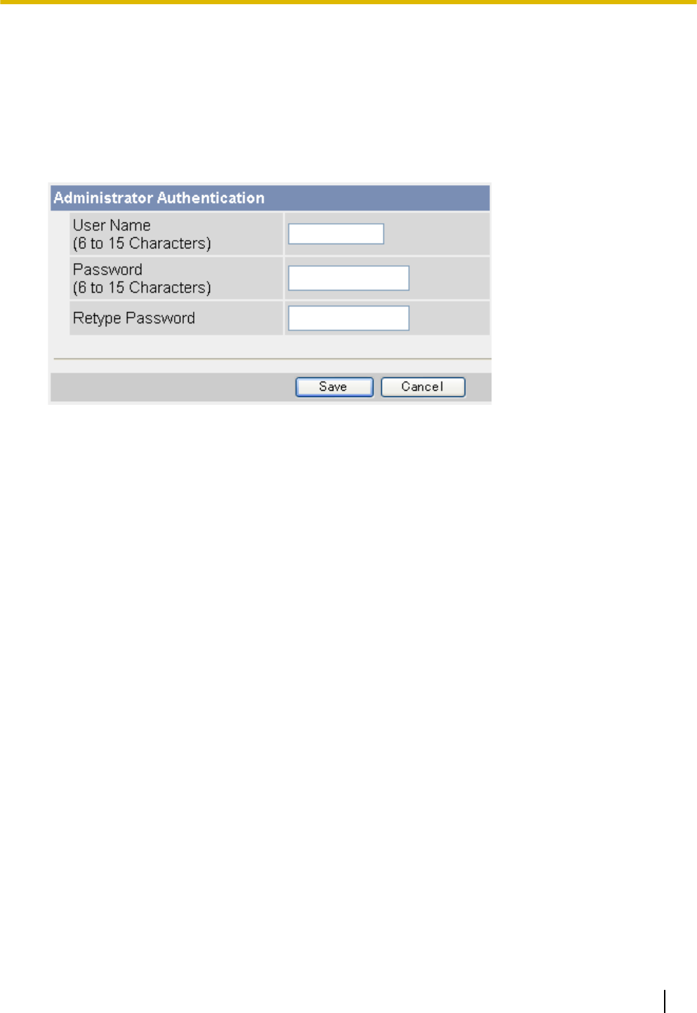
6.2 Changing the Administrator User Name and
Password
For security, we recommend setting a user name and password that uses many characters and is difficult to
guess. Change the password periodically for added security.
1. Click the [Setup] tab.
2. On the left side of the screen under [Account], click [Administrator].
3. Under [Administrator Authentication], enter the user name and password, then re-enter the password for
verification.
•See Page 206 for a list of valid characters. Note that [Space], ["], ['], [&], [<], [>], and [:] cannot be
entered.
4. Click [Save].
Operating Instructions 151
6.2 Changing the Administrator User Name and Password
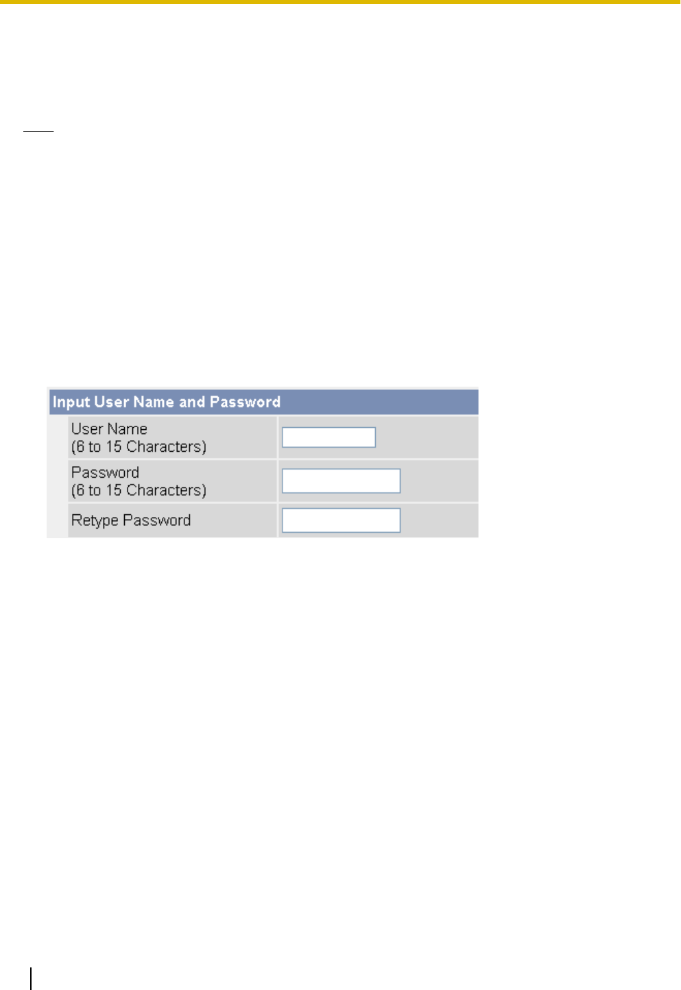
6.3 General Users
Up to 50 general user accounts can be created. Each user has his or her own user name and password, and
you can control the camera features that are available to general users.
Note
•For security, we recommend setting user names and passwords that are difficult to guess. Change the
passwords periodically for added security.
•When general users access the camera, the [Internet], [Setup], and [Maintenance] tabs are never
displayed. The [Multi] and [Buffered Image] tabs will be displayed if you allow general users to access
those pages.
Creating or modifying a general user account
1. Click the [Setup] tab.
2. On the left side of the screen under [Account], click [General User].
3. Under [User ID List], click [Create].
•Up to 50 general user accounts can be created.
•To modify an existing user account, select the general user account you want to modify, then click
[Modify].
152 Operating Instructions
6.3 General Users
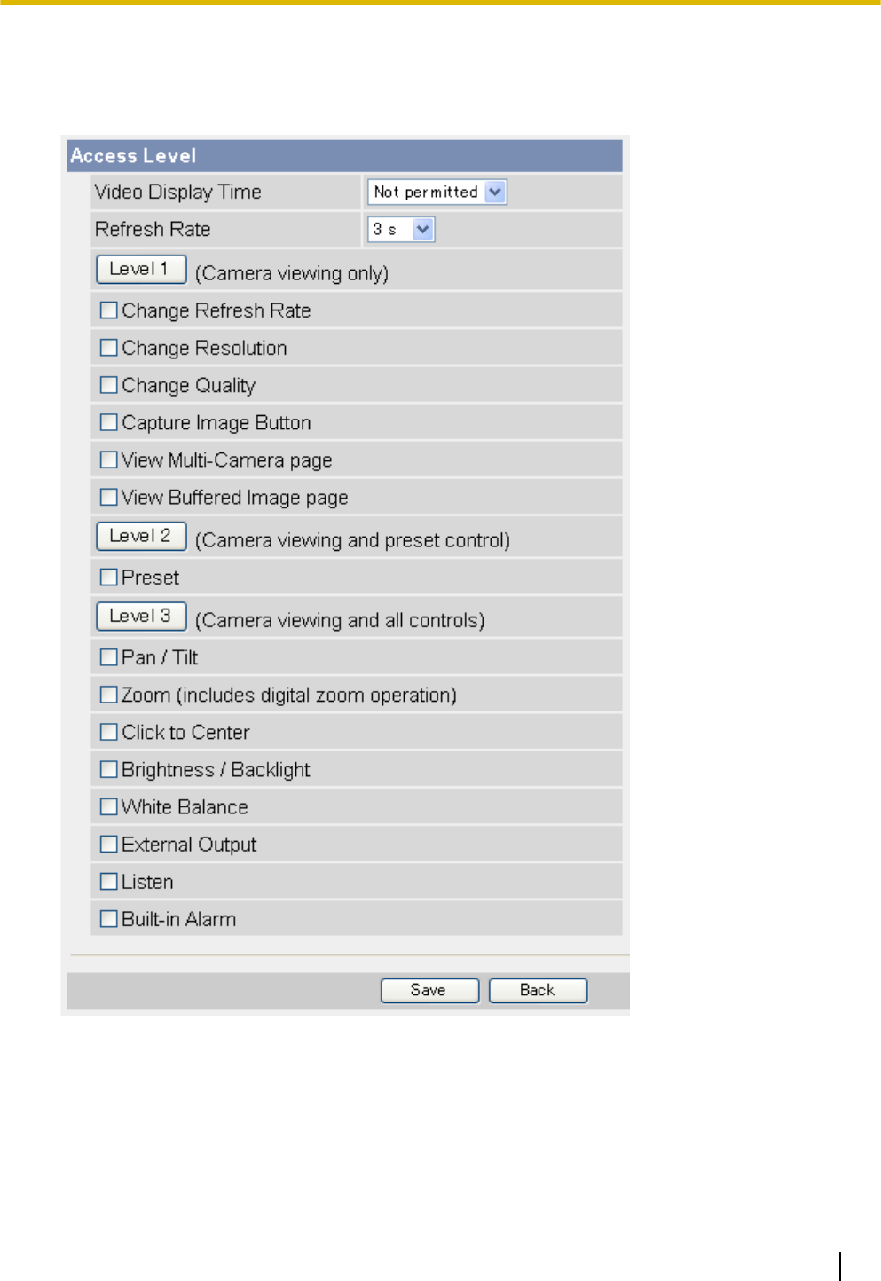
4. Under [Input User Name and Password], enter the user name and password, then re-enter the password
for verification.
•See Page 206 for a list of valid characters. Note that [Space], ["], ['], [&], [<], [>], and [:] cannot be
entered.
5. Set the following parameters as desired.
a. Under [Access Level], select the desired setting for [Video Display Time].
–[Unlimited]: The user can view video images ([H.264], [MPEG-4], or [MJPEG]) from the camera
without restriction.
–[Not permitted]: The user can view only still images.
–[10 s]–[60 min]: The user can view video images for the selected amount of time, after which the
user can view only still images.
Operating Instructions 153
6.3 General Users

b. Select the desired setting for [Refresh Rate]. Still images viewed by the user will be refreshed at this
rate.
c. Select the features the user is allowed to use.
•You can select features individually, or click [Level 1], [Level 2], or [Level 3] to enable the
corresponding group of features.
•BL-C230 only: [External Output] can be selected.
6. Click [Save].
Note
•Screen content varies by model number.
•Users can click to center when using the ActiveX zoom feature, even if the click to center feature is
disabled. Users can click to center the image within the zoomed area, but the lens will not pan or tilt.
•When [Change Resolution] is disabled, users may not be able to change the refresh rate even if
[Change Refresh Rate] is enabled, due to feature limitations based on the [Streaming Format] setting
on the [Video Streaming] page. For more information on these limitations, see Page 209.
•Images displayed on the multi-camera page may be reduced in size when [View Multi-Camera page]
is enabled, therefore we recommend enabling [Change Resolution] as well.
Deleting a general user account
1. Click the [Setup] tab.
2. On the left side of the screen under [Account], click [General User].
3. Under [User ID List], select the general user account you want to delete, then click [Delete].
4. Confirm that you have selected the desired general user account to be deleted, then click [Delete].
5. Click [OK].
154 Operating Instructions
6.3 General Users
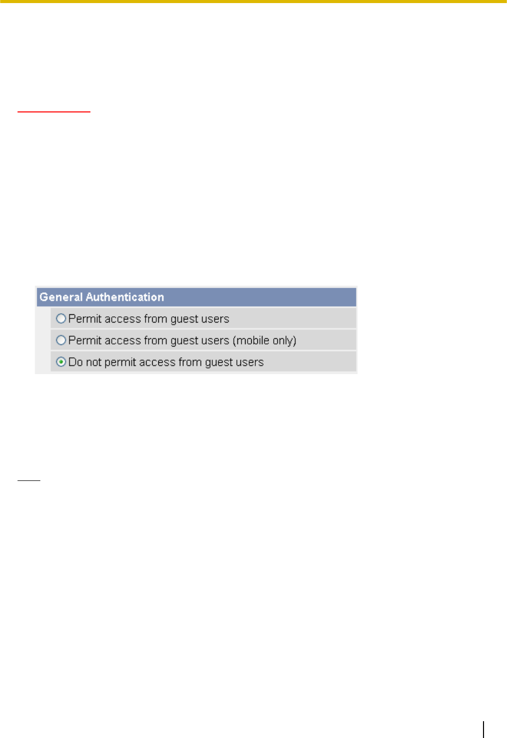
6.4 Guest Users
Guest users are anonymous users, and they do not need to enter a user name or password to access the
camera. You can control the camera features that are available to guest users, and you can restrict guest user
access altogether.
IMPORTANT
To prevent unauthorized access to the camera, it is important to manage who can access the camera
through the use of user names and passwords. Because the camera can be accessed from the Internet,
it is possible that the camera may be accessed by unknown individuals, including those who are commonly
known as “hackers”, to whom you do not want to allow access. If you choose to allow guest access (i.e.,
anonymous access), there is a risk that unknown individuals will access the camera and view camera
images. You have the option of allowing guest access, but it is strongly recommended that you do not allow
guest access, and rather create general user accounts and assign secret user names and passwords for
use by known individuals only.
Allowing/restricting guest users to access the camera
1. Click the [Setup] tab.
2. On the left side of the screen under [Account], click [Administrator].
3. Under [General Authentication], select the desired setting.
–[Permit access from guest users]: Guest users can access the camera.
–[Permit access from guest users (mobile only)]: Guest users can access the camera’s mobile phone
page only.
–[Do not permit access from guest users]: Guest users cannot access the camera.
4. Click [Save].
Note
•When [Permit access from guest users] is selected, no authentication dialog is displayed when you
access the camera, and the [Login] tab is displayed on the top page. Click this tab to log in to the
camera as the administrator or as a general user. For more information, see Page 158.
Changing the features available to guest users
1. Make sure you configured the camera to allow guest users to access the camera (explained above).
2. Click the [Setup] tab.
3. On the left side of the screen under [Account], click [General User].
Operating Instructions 155
6.4 Guest Users
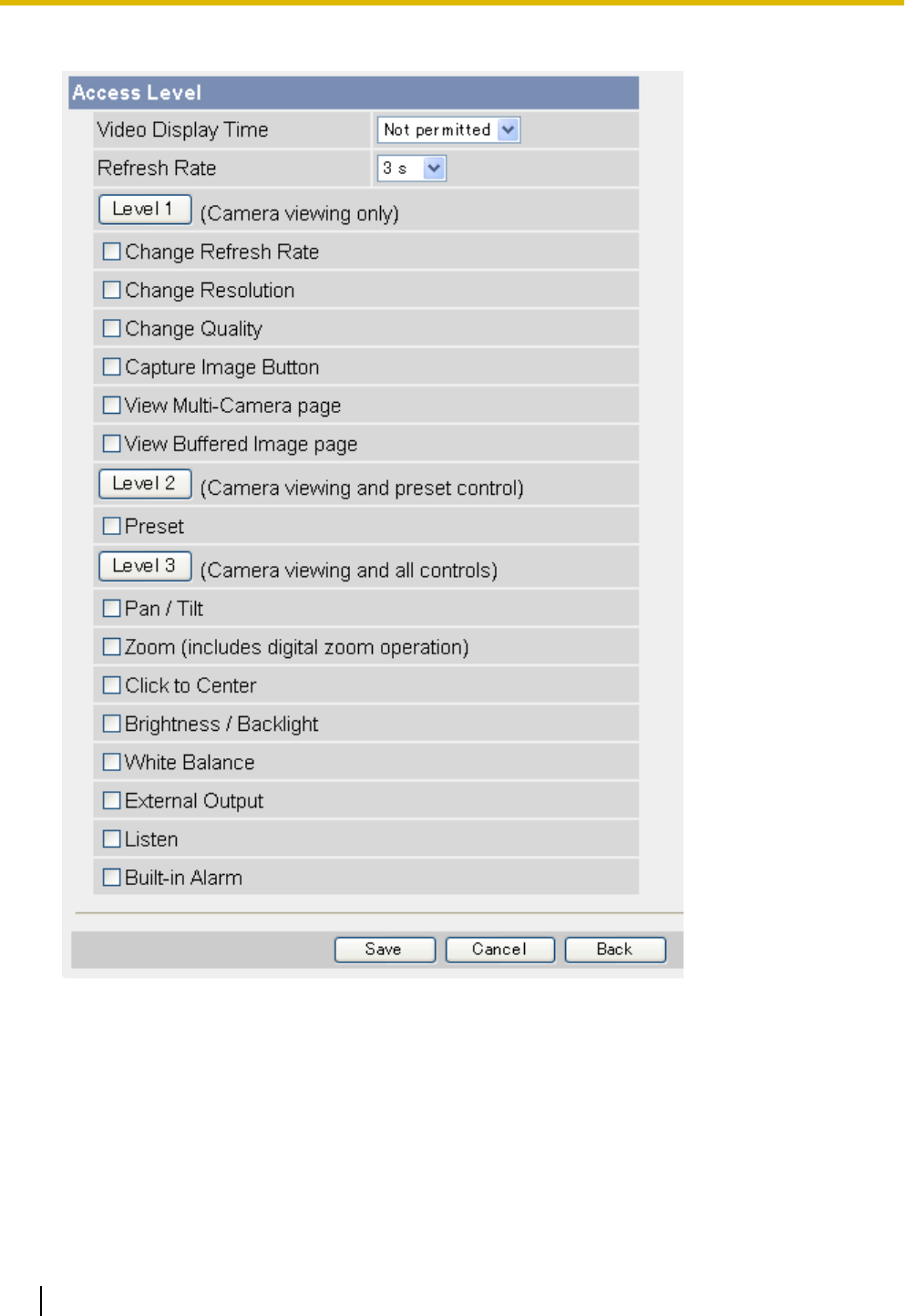
4. Under [User ID List], select [Guest User], then click [Modify].
5. Set the following parameters as desired.
a. Under [Access Level], select the desired setting for [Video Display Time].
–[Unlimited]: The user can view video images ([H.264], [MPEG-4], or [MJPEG]) from the camera
without restriction.
–[Not permitted]: The user can view only still images.
–[10 s]–[60 min]: The user can view video images for the selected amount of time, after which the
user can view only still images.
b. Select the desired setting for [Refresh Rate]. Still images viewed by the user will be refreshed at this
rate.
c. Select the features the user is allowed to use.
156 Operating Instructions
6.4 Guest Users

•You can select features individually, or click [Level 1], [Level 2], or [Level 3] to enable the
corresponding group of features.
•BL-C230 only: [External Output] can be selected.
6. Click [Save].
Note
•Screen content varies by model number.
•Users can click to center when using the ActiveX zoom feature, even if the click to center feature is
disabled. Users can click to center the image within the zoomed area, but the lens will not pan or tilt.
•When [Change Resolution] is disabled, users may not be able to change the refresh rate even if
[Change Refresh Rate] is enabled, due to feature limitations based on the [Streaming Format] setting
on the [Video Streaming] page. For more information on these limitations, see Page 209.
•Images displayed on the multi-camera page may be reduced in size when [View Multi-Camera page]
is enabled, therefore we recommend enabling [Change Resolution] as well.
Operating Instructions 157
6.4 Guest Users

6.5 The Login Tab
When guest users are allowed to access the camera (see Page 155), no authentication dialog is displayed
when you access the camera, and the [Login] tab is displayed on the top page. Click this tab to log in to the
camera as the administrator or as a general user.
158 Operating Instructions
6.5 The Login Tab

7 Advanced Settings
7.1 Changing Image Display Settings
You can change the camera name and the way camera images are displayed each time the camera is
accessed. Use the procedure below to change the following settings:
–Camera name
–Refresh rate, image resolution, and image quality for the single camera page and for the multi camera
page
–Streaming method for the single camera page
–Default image resolution for when viewing with your mobile phone
–Overlay settings (control whether the date and time, a text message, the camera’s trigger status, and
backlight correction status are displayed)
–Default display language
–Banner settings (control whether a banner is displayed on the single camera page, and the properties of
the banner)
1. Click the [Setup] tab.
Operating Instructions 159
7.1 Changing Image Display Settings
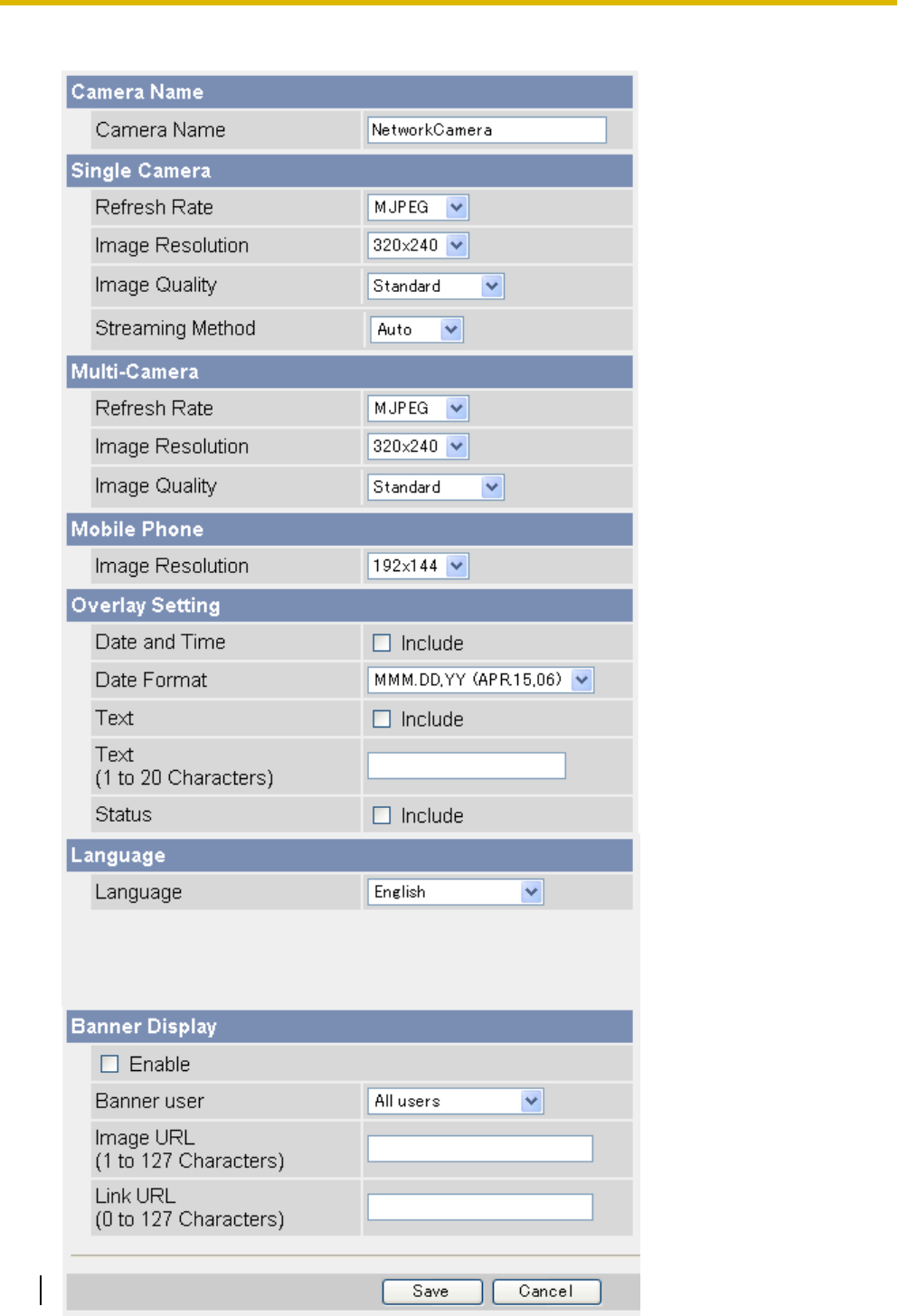
2. On the left side of the screen under [Advanced], click [Image Display].
160 Operating Instructions
7.1 Changing Image Display Settings

3. Set the following parameters as desired.
a. Under [Camera Name], change the camera name as desired (max. 15 characters).
•See Page 206 for a list of valid characters. Note that [Space], ["], ['], [&], [<], and [>] cannot be
entered.
b. Under [Single Camera], select the desired default refresh rate, image resolution, and image quality (for
when viewing MJPEG or still images) and streaming method (for when viewing H.264 or MPEG-4
images).
c. Under [Multi-Camera], select the desired default refresh rate, image resolution, and image quality (for
when viewing MJPEG or still images).
d. Under [Mobile Phone], select the desired default image resolution for when viewing still images with
your mobile phone.
e. Under [Overlay Setting], select what information is displayed in the overlay displayed on the single
camera page, multi camera page, and buffered images page. See Page 11 for an example of a camera
image overlays. Screen content varies by model number.
i.
Select whether you want to display a time stamp in the upper left corner of camera images, then
select the desired format for the time stamp. To select 12-hour or 24-hour time format, see
Page 140.
ii.
Select whether you want to display a text message in the lower left corner of camera images, then
enter the desired text (max. 20 characters).
•See Page 206 for a list of valid characters. Note that ["], ['], [&], [<], and [>] are not available.
iii.
Select whether you want to display status in the upper right corner of camera images.
•[O] will be displayed when the sound detection feature has been triggered.
•[M] will be displayed when the motion detection feature has been triggered.
•[S] will be displayed when the built-in sensor has been triggered.
•[1] or [2] will be displayed when external sensor 1 or 2, respectively, has been triggered.
• will be displayed while the backlight correction feature is on.
Note
•When viewing images at 192 ´ 144 pixel resolution, status overlay is not displayed.
•If the external sensor uses a ground to open signal (i.e., if you select [Rising: GND to Open
(High).] when configuring the alarm trigger), the corresponding alarm number is displayed
when the sensor is not being triggered. While the sensor is being triggered, the alarm
number disappears from the overlay.
f. Under [Language], select the camera’s display language.
•The user can change the display language on the top page if desired.
•If you select [Korean], Korean is displayed as the initial language when clicking the [Top], [Single],
[Multi], and [Buffered Image] tabs. All other pages are displayed in English.
g. Under [Banner Display], select the desired parameters for the banner displayed on the single camera
page.
i.
Select whether you want to display a banner.
ii.
Select which users the banner is displayed for.
iii.
Enter the URL (max. 127 characters*1), including http:// if necessary, of the banner image file.
This specifies the location of the image file that is displayed as the banner. Note that the file
extension of the image file must be .jpg or .png.
Note
•If authentication is required to display the image URL, an authentication window will be
displayed when you access the single camera page.
•Each time the single camera page is accessed, the camera accesses the URL of the banner
image file and reads the file. Be aware that the computer/server that contains the banner
image file may become burdened if the single camera page is accessed or refreshed
frequently.
Operating Instructions 161
7.1 Changing Image Display Settings

iv.
Enter the URL (max. 127 characters*1), including http:// if necessary, of the banner’s link. This
specifies the web page or image that is displayed when the user clicks the banner.
4. Click [Save].
*1 [Space], ["], ['], [&], [<], and [>] cannot be entered.
162 Operating Instructions
7.1 Changing Image Display Settings
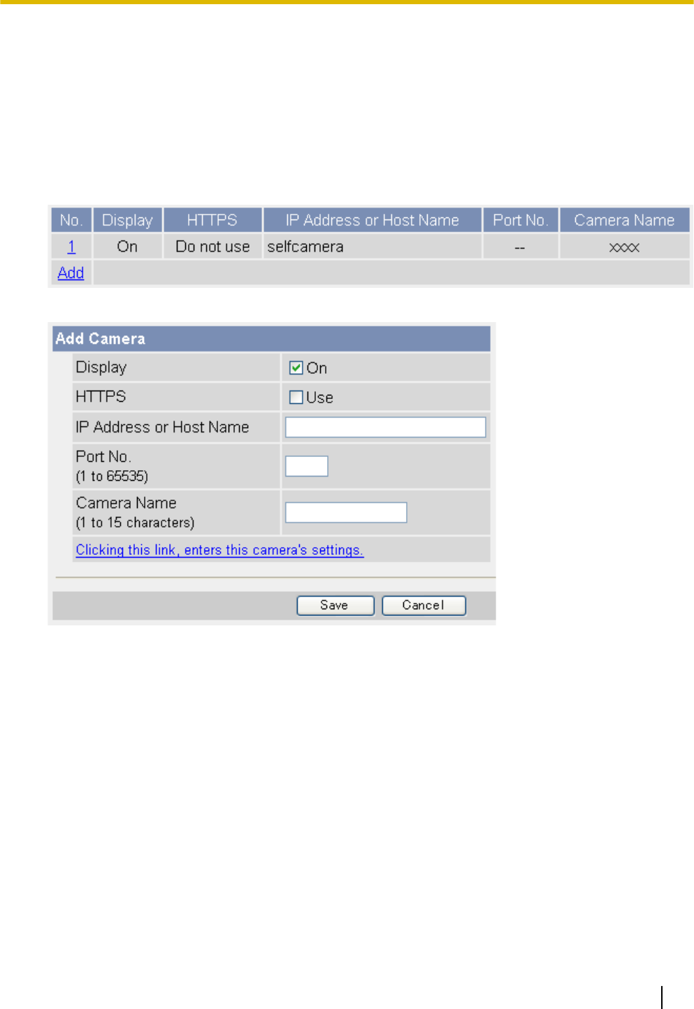
7.2 Registering Multiple Cameras
You can register other Panasonic Network Cameras to this camera’s [Multi] tab. This allows you to view images
from up to 16 cameras by simply accessing this camera and clicking the [Multi] tab.
Registering other cameras to this camera
1. Click the [Setup] tab.
2. On the left side of the screen under [Advanced], click [Multi-Camera].
3. Click [Add].
4. Under [Add Camera], check [Display].
5. Check [HTTPS] if the corresponding camera is configured to use HTTPS.
•If this setting does not match the camera’s setting, the camera cannot be accessed from the [Multi]
page.
6. Enter the IP address or host name of the other camera.
•An IPv6 address can be specified; note that the IPv6 address must be enclosed in brackets.
•To allow users to view cameras over the Internet, enter the camera’s global IP address or host name
here (i.e., the IP address or host name needed to access the other camera over the Internet).
•To allow users to view cameras over the LAN, enter the local IP address of the other camera here (i.e.,
the IP address needed to access the other camera over the LAN).
•See Page 206 for a list of valid characters. Note that [Space], ["], ['], [&], [<], [>], [#], [%], [=], [+], and
[?] cannot be entered.
•You can register this camera to the multi camera page by simply clicking [Clicking this link, enters this
camera's settings.].
7. Enter the port number of the other camera.
Operating Instructions 163
7.2 Registering Multiple Cameras
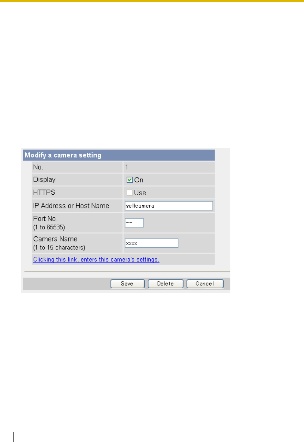
8. Enter the camera’s name (max. 15 characters). This is the camera name that is displayed on the [Multi]
page and does not need to match the camera name set on the other camera.
•Only ASCII characters are available (see Page 206). Note that [Space], ["], ['], [&], [<], [>], [#], [%],
[=], [+], [?], and [:] cannot be entered.
9. Click [Save].
Note
•If you register a camera that does not support H.264 to the multi camera page of a camera that supports
H.264, only MJPEG images from the camera that does not support H.264 can be viewed.
•If you register a camera that supports H.264 to the multi camera page of a camera that does not support
H.264, only MJPEG images from the camera that supports H.264 can be viewed.
Modifying previously registered cameras
1. Click the [Setup] tab.
2. On the left side of the screen under [Advanced], click [Multi-Camera].
3. Click the desired camera number.
4. Change the settings as desired.
5. Click [Save].
Deleting previously registered cameras
1. Click the [Setup] tab.
2. On the left side of the screen under [Advanced], click [Multi-Camera].
3. Click the desired camera number.
4. Click [Delete].
5. Click [OK].
Changing the order of cameras on the [Multi] tab
1. Click the [Setup] tab.
164 Operating Instructions
7.2 Registering Multiple Cameras

2. On the left side of the screen under [Advanced], click [Multi-Camera].
3. Under [Change Camera Order], select the number of the camera you would like to move, and select the
number you would like to move the camera to. The 2 cameras will switch places in the list.
•For example, to switch camera 2 and camera 1, select [Switch No.] 2 [with No.] 1.
4. Click [Execute].
Operating Instructions 165
7.2 Registering Multiple Cameras
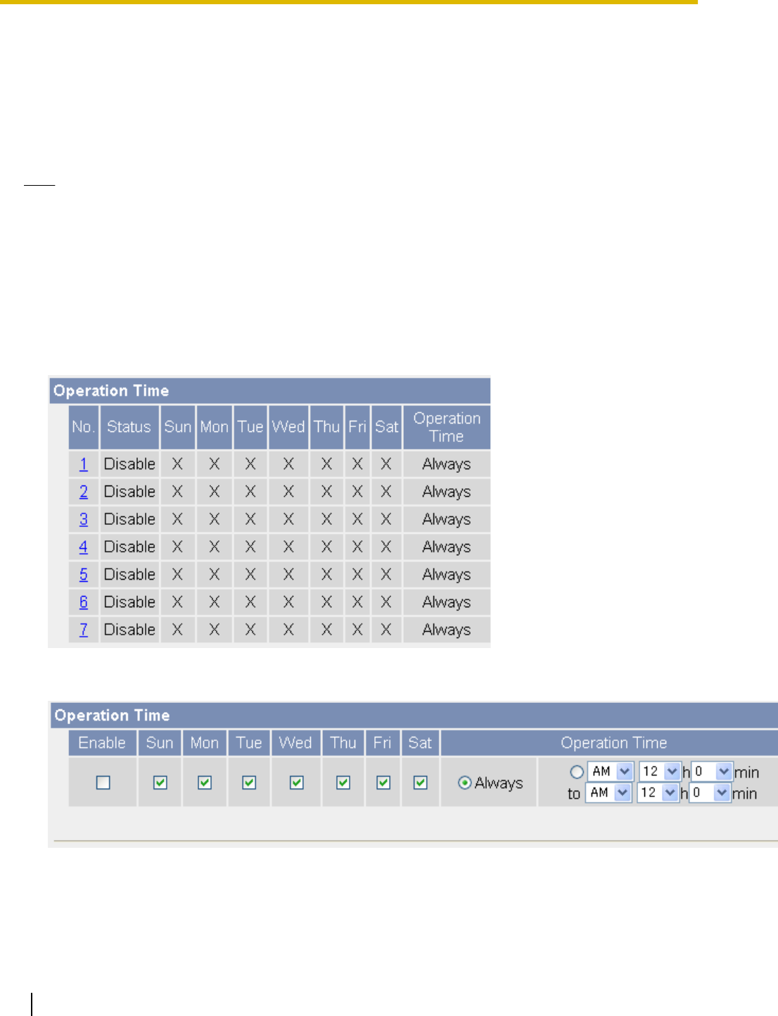
7.3 Specifying Operation Times
You can specify the days and times during which general users and guest users can view camera images (the
administrator can always view camera images). When the camera is accessed outside of the operation time,
the camera image on the single camera page, multi camera page, and buffered image page is displayed as a
gray or black screen. Additionally, [The operation time has ended.] is displayed on the single camera page.
Up to 7 different operation times can be set.
Note
•Your privacy may be compromised if you set this feature incorrectly. To confirm that you have made
the correct settings, access the camera as a general user or guest user during a time the camera is
outside of the operational time to confirm that camera images cannot be seen.
•Make sure the camera’s date and time setting is correct in order for this feature to function as desired.
•If H.264 or MPEG-4 images are being viewed when the camera’s operation time ends, the last image
will be displayed for about 20 seconds, followed by a black screen when viewing H.264 images and a
gray screen when viewing MPEG-4 images. If MJPEG are being viewed when the camera’s operation
time ends, the last image is displayed continuously as a still image.
1. Click the [Setup] tab.
2. On the left side of the screen under [Advanced], click [Operation Time].
3. Select the desired operation time setting number.
•If No. 1–7 are disabled, camera images can always be seen.
4. Check [Enable] to enable this operating time setting number, then set the desired operation days and times.
•Click [Always] to allow camera images to be seen at any time of day on the days which have a check
mark under them.
5. Click [Save].
166 Operating Instructions
7.3 Specifying Operation Times

Note
•If 2 operating time settings overlap, the [Enable] setting takes priority.
In the example below, the camera is set to be disabled on Mondays (in setting No. 1) and is set to be
disabled on Tuesdays (in setting No. 2). However, the camera can be accessed on both Mondays and
Tuesdays because these days are each enabled by one of the settings.
Operating Instructions 167
7.3 Specifying Operation Times
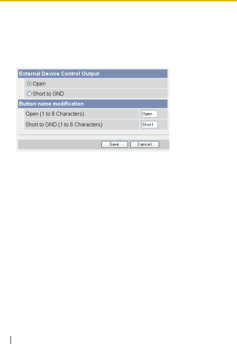
7.4 Controlling the External Output Terminal
(BL-C230 Only)
If a device is connected to the output terminals of the external I/O interface (see the Installation Guide for
connection information), follow the procedure below to configure the camera to interact with the device properly
and to rename the external output buttons displayed in the operation bar.
1. Click the [Setup] tab.
2. On the left side of the screen under [Advanced], click [External Output].
3. Under [External Device Control Output], select the appropriate setting.
–[Open]: The camera’s internal transistor turns off and the output has high impedance (logical HIGH).
–[Short to GND]: The camera’s internal transistor turns on and the output is shorted to the GND (logical
LOW).
4. Under [Button name modification], modify the names of the external output buttons displayed in the
operation bar if necessary. Note that [Space], ["], ['], [&], [<], and [>] cannot be entered.
5. Click [Save].
168 Operating Instructions
7.4 Controlling the External Output Terminal (BL-C230 Only)
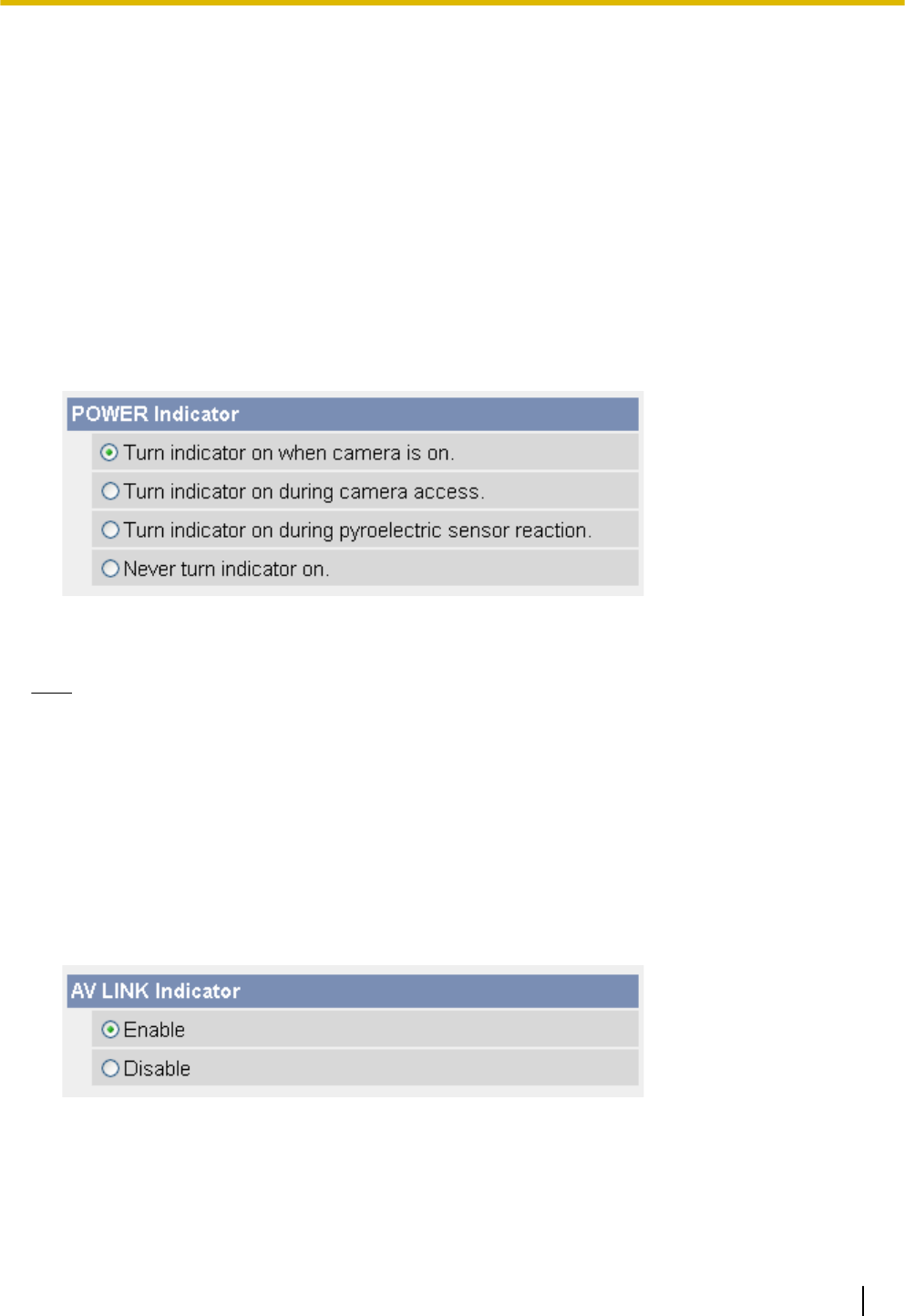
7.5 Changing the Indicator Display
The POWER indicator
The POWER indicator can be used to indicate when the camera is being accessed, however you can set the
camera so that the indicator is:
–Always on (green) during normal operation
–On (green) only when the camera is being accessed
–On (orange) only when the camera’s built-in sensor is being triggered
This setting is useful when deciding where to mount the camera, because the indicator will indicate when
the built-in sensor has been triggered, allowing you to change the location of the camera to a more
appropriate location if necessary.
–Always off during normal operation
1. Click the [Setup] tab.
2. On the left side of the screen under [Advanced], click [Indicator Control].
3. Select the desired setting.
4. Click [Save].
Note
•If the POWER indicator lights in any color other than green, refer to 1.2 POWER Indicator Issues in
the Troubleshooting Guide.
The AV LINK indicator (BL-C210A/BL-C230A only)
The AV LINK indicator can be used to indicate the status of the camera’s communication with a registered TV,
however you can set the camera so that the indicator is:
–Enabled (see The AV LINK indicator (BL-C210A/BL-C230A only) in the Troubleshooting Guide for details)
–Disabled; i.e., the AV LINK indicator lights only when the camera is in registration mode
1. Click the [Setup] tab.
2. On the left side of the screen under [Advanced], click [Indicator Control].
3. Select the desired setting.
4. Click [Save].
Operating Instructions 169
7.5 Changing the Indicator Display
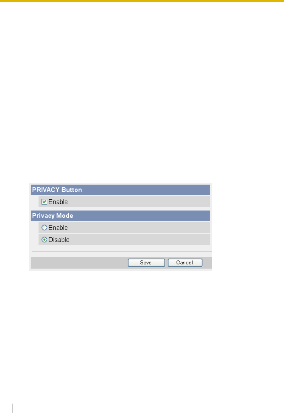
7.6 Privacy Mode
Privacy mode allows you to protect your privacy by hiding the lens inside the camera, preventing camera
images from being seen. When privacy mode is activated:
–The POWER indicator turns red so that you can easily see that privacy mode is activated.
–No camera images are buffered or transferred.
–The camera image changes to a gray or black screen if privacy mode is activated while viewing camera
images.
–If privacy mode is already activated when you try to access the camera, a dialog will be displayed asking
if you want to disable privacy mode. In order to disable privacy mode, the administrator’s user name and
password must be entered.
Note
•BL-C210A/BL-C230A only: You cannot turn privacy mode on while the camera is in registration mode
(see Page 172).
Turning privacy mode on
You can turn privacy mode on by:
–Pressing the camera’s PRIVACY button (the POWER indicator will turn from green to red).
–Accessing the camera with a PC as the administrator.
1. Click the [Setup] tab.
2. On the left side of the screen under [Advanced], click [Privacy Mode].
3. Under [Privacy Mode], select [Enable].
4. Click [Save].
–Accessing the camera from a mobile phone (see Page 92) as the administrator.
Turning privacy mode off
You can turn privacy mode off by:
–Pressing the camera’s PRIVACY button (the POWER indicator will turn from red to green).
–Accessing the camera with a PC. When [Privacy Mode is enabled. Do you wish to disable?] is displayed,
click [Disable Privacy Mode] and enter the administrator user name and password if prompted.
–Accessing the camera from a mobile phone (see Page 92) as the administrator.
170 Operating Instructions
7.6 Privacy Mode

Disabling the PRIVACY button
You can disable the PRIVACY button so that privacy mode cannot be turned on or off by pressing the
PRIVACY button.
1. Click the [Setup] tab.
2. On the left side of the screen under [Advanced], click [Privacy Mode].
3. Under [PRIVACY Button], uncheck [Enable].
4. Click [Save].
Operating Instructions 171
7.6 Privacy Mode
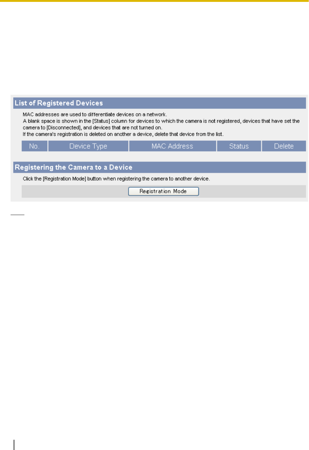
7.7 Managing Registered Devices (BL-C210A/
BL-C230A Only)
A compatible Panasonic VIERA TV can be used to view camera images and configure certain camera features.
In order to use this feature, the camera and TV must be registered to each other. This page allows you to
confirm and delete devices (TVs) that are registered to the camera. Additionally, you can set the camera to
Registration Mode, so that it can be registered to additional TVs.
For details on registration, refer to the Setup Guide (for VIERA Connection). For details on viewing camera
images and configuring the camera with a TV, refer to the Operating Instructions (for VIERA Connection).
Note
•This page is not available when accessing the camera using HTTPS.
•If the camera is accessed while the camera is in registration mode, [Registering...] is displayed.
Confirming a TV’s status
1. Click the [Setup] tab.
2. On the left side of the screen under [Advanced], click [Registered Devices].
•The following information is displayed.
–The type of device
–The device’s MAC address
–The device’s status
[X] is displayed in the [Status] column if the TV is not turned on, if the camera is not registered to
the TV, or if the TV has set the camera to [Disable]. If the camera’s registration is deleted on the
TV, delete that TV from the camera’s registered devices list.
Deleting a TV
1. Click the [Setup] tab.
2. On the left side of the screen under [Advanced], click [Registered Devices].
3. Click [Delete] to delete a TV.
•After deleting a TV, we recommend deleting this camera’s registration from that TV.
172 Operating Instructions
7.7 Managing Registered Devices (BL-C210A/BL-C230A Only)

Preparing to register the camera to a TV (registration mode)
You can also set the camera to registration mode by pressing and holding the camera’s PRIVACY button for
about 3 seconds, until the AV LINK indicator flashes. If the camera is not registered to a TV within 5 minutes,
registration mode is canceled.
1. Click the [Setup] tab.
2. On the left side of the screen under [Advanced], click [Registered Devices].
3. Click the [Registration Mode] button when registering the camera to another device.
•You may now register the camera to the TV. Refer to the Setup Guide (for VIERA Connection) for
details.
•The AV LINK indicator flashes orange while the camera is in registration mode.
•After 5 minutes, registration mode is cancelled if the camera has not been registered to a TV.
Note
•Registration mode cannot be turned on while the camera is in privacy mode (see Page 170).
•The camera can be registered to up to 4 TVs.
•While the camera is in registration mode:
–No camera images are buffered or transferred.
–The built-in alarm does not sound.
–Privacy mode cannot be turned on.
Operating Instructions 173
7.7 Managing Registered Devices (BL-C210A/BL-C230A Only)
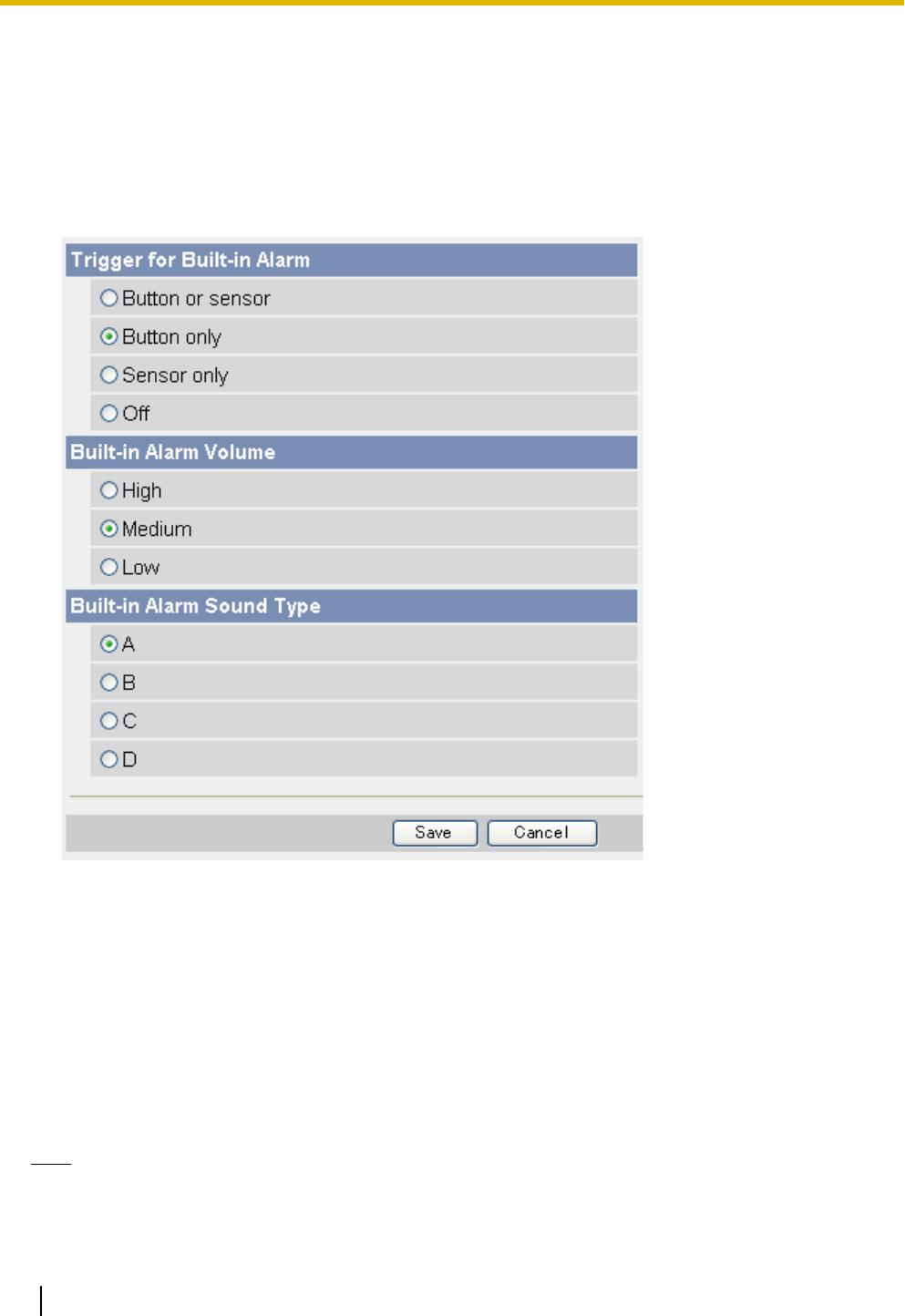
7.8 Built-in Alarm Settings
The camera’s built-in alarm can sound when the built-in sensor, external sensor, or motion detection is
triggered. You can set when the built-in alarm sounds, as well as the built-in alarm volume and the built-in
alarm sound type. After saving these settings, confirm the built-in alarm volume and sound type by clicking
[Sound Alarm] on the single camera page.
1. Click the [Setup] tab.
2. On the left side of the screen under [Advanced], click [Built-in Alarm].
3. Under [Trigger for Built-in Alarm], select when the built-in alarm sounds.
–[Button or sensor]: The built-in alarm sounds when [Sound Alarm] is clicked on the single camera page
and when the built-in sensor, external sensor, or motion detection is triggered.
–[Button only]: The built-in alarm sounds only when [Sound Alarm] is clicked on the single camera page.
–[Sensor only]: The built-in alarm sounds only when the built-in sensor, external sensor, or motion
detection is triggered, and the [Built-in Alarm] button is not displayed in the operation bar.
–[Off]: The built-in alarm does not sound, and the [Built-in Alarm] button is not displayed in the operation
bar.
4. Under [Built-in Alarm Volume], select the volume of the built-in alarm.
5. Under [Built-in Alarm Sound Type], select the built-in alarm sound type.
6. Click [Save].
Note
•The built-in alarm does not sound when the sound detection feature is triggered (see Page 54).
174 Operating Instructions
7.8 Built-in Alarm Settings

•When you set [Trigger for Built-in Alarm] to [Button or sensor] or [Sensor only], configure the camera
to buffer and transfer images (see Page 54) so that the built-in alarm can sound when the built-in
sensor, external sensor, or motion detection is triggered.
•The built-in alarm does not sound even if [Trigger for Built-in Alarm] is set to [Button or sensor] or
[Sensor only] while the camera is in privacy mode (Page 170) or in registration mode (Page 172).
Operating Instructions 175
7.8 Built-in Alarm Settings

8 Camera Administration and Maintenance
8.1 Confirming Camera Status
You can confirm various camera status information on the [Status] page such as:
–Detailed camera information, including the firmware version number and MAC address
–Detailed network information
–Dynamic DNS status
–UPnP™ status
–The status of various protocols (such as FTP, HTTP, SMTP, etc.) and whether or not there have been any
errors
The information displayed on this page can help you when the camera is not functioning as you expect it to.
Refer to this information for troubleshooting assistance.
1. Click the [Maintenance] tab.
2. On the left side of the screen under [Maintenance], click [Status].
3. Confirm the desired information.
Note
•See the Panasonic Network Camera support site (http://panasonic.net/pcc/support/netwkcam/) for
details about the information displayed on this page.
176 Operating Instructions
8.1 Confirming Camera Status

8.2 Confirming Wireless Status (BL-C230 Only)
You can confirm various wireless information on the [Wireless Status] page such as:
–The status of the wireless connection to the wireless router
–The MAC address of the camera’s wireless module
–The quality of the wireless communication between the camera and the wireless router
The information displayed on this page can help you when the camera is not functioning in wireless mode as
you expect it to. Refer to this information for troubleshooting assistance.
1. Click the [Maintenance] tab.
2. On the left side of the screen under [Maintenance], click [Wireless Status].
3. Confirm the desired information.
Note
•If your wireless router uses MAC address filtering, enter the MAC address of the camera and the MAC
address of the camera’s wireless module when setting your wireless router’s MAC address filtering
feature. The MAC address of the camera’s wireless module is displayed on the [Wireless Status] page
next to [MAC address of Wireless module]. You can confirm the camera’s MAC address on the
[Status] page (see Page 176).
•The signal strength of the wireless connection to the wireless router is displayed next to [Radio
Condition] as follows:
–[Good]: When the signal strength is 50%–100%
–[Normal]: When the signal strength is 15%–49%
–[Weak]: When the signal strength is 1%–14%
–[No connection]: When there is no signal (0%)
•If you still cannot access the camera in wireless mode, see 1.4 Wireless Connection Issues (BL-C230
Only) in the Troubleshooting Guide.
•See the Panasonic Network Camera support site (http://panasonic.net/pcc/support/netwkcam/) for
details about the information displayed on this page.
Operating Instructions 177
8.2 Confirming Wireless Status (BL-C230 Only)

8.3 Confirming Session Status
You can confirm various client session information on the [Session Status] page such as:
–The number of active video (H.264, MPEG-4, and MJPEG) and audio sessions
–Multicast session status
1. Click the [Maintenance] tab.
2. On the left side of the screen under [Maintenance], click [Session Status].
3. Confirm the desired information.
Note
•Information for the following session types is not displayed:
–Mobile phone access
–Still image viewing
–Accessing the [Top], [Setup], [Internet], [Maintenance], and [Support] pages
178 Operating Instructions
8.3 Confirming Session Status

8.4 Confirming Alarm Logs
The camera records log information each time the camera is triggered and each time the camera’s privacy
feature is turned on and off. Up to 50 events are logged, and each event includes the date, time, and type
(built-in sensor, external sensor 1, external sensor 2, motion detection, sound detection, or privacy mode on/
off).
1. Click the [Maintenance] tab.
2. On the left side of the screen under [Maintenance], click [Alarm Log].
3. Confirm the desired information.
Note
•When the camera is restarted, the alarm log content is deleted.
•You can configure the camera to send a daily log by E-mail that reports the status of triggers 1–5 (see
Page 87).
Operating Instructions 179
8.4 Confirming Alarm Logs
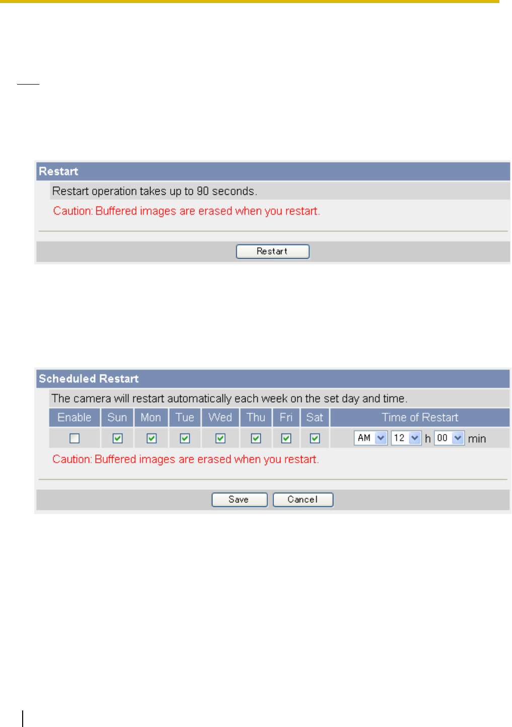
8.5 Restarting the Camera
You can restart the camera from the [Restart] page.
Note
•When the camera is restarted, all images buffered in the internal memory are deleted.
•When the camera is restarted, the alarm log content is deleted.
•The amount of time it takes for the BL-C210 and the BL-C230 to restart is different.
1. Click the [Maintenance] tab.
2. On the left side of the screen under [Maintenance], click [Restart].
3. Click [Restart].
Automatically restarting the camera
You can set the camera restart itself automatically periodically.
1. Click the [Maintenance] tab.
2. On the left side of the screen under [Maintenance], click [Restart].
3. Under [Scheduled Restart], click [Enable].
4. Select the days and times you would like the camera to automatically restart.
5. Click [Save].
180 Operating Instructions
8.5 Restarting the Camera

8.6 Updating the Camera’s Firmware
You can update the camera’s firmware from the [Update Firmware] page.
1. Download the latest firmware from the Panasonic Network Camera website
(http://panasonic.net/pcc/support/netwkcam/) and save it on your PC.
2. Click the [Maintenance] tab.
3. On the left side of the screen under [Maintenance], click [Update Firmware].
4. Click [Update Firmware]. The camera will automatically restart.
5. After the camera restarts, a dialog prompts you to select the firmware file.
6. Click [Browse...]. A dialog prompts you to specify the location of the firmware file.
7. Select the firmware file you downloaded from the Panasonic Network Camera website and click [Open].
The selected file name is displayed.
8. Confirm the file name, then click [Update Firmware].
•The [Updating firmware.] screen is displayed, and then the [Restarting now...] screen is displayed.
When the firmware update is complete, the camera’s top page is displayed.
Note
•The firmware update may take 10 minutes or longer depending on the network environment.
9. Confirm the camera’s new firmware version on the top page.
Note
•Do not turn off the power during a firmware update.
•All images buffered in the internal memory are deleted when the firmware is updated.
•All alarm logs are deleted when the firmware is updated.
•You can also use the Setup Program to update the camera’s firmware (see Page 202).
•The camera’s current firmware version can be confirmed on the [Top] page and the [Status] page.
•The camera can only be accessed using HTTP while updating the firmware. If HTTPS was used to
begin the firmware update, the camera will switch to HTTP during the update, and then return to HTTPS
when the update is completed.
•After updating the firmware, if the top page is not displayed when accessing the camera in IPv6 mode,
use the Setup Program to find the camera and access it.
Operating Instructions 181
8.6 Updating the Camera’s Firmware

8.7 Saving Settings in a Configuration File
You can save a configuration file (i.e., a backup of the camera’s settings) on your PC and restore the settings
later if desired (see Page 183).
1. Click the [Maintenance] tab.
2. On the left side of the screen under [Maintenance], click [Save Settings].
3. Click [Save]. A dialog prompts you to specify a location to save the configuration file.
4. Specify a location to save the file, then click [Save].
Note
•The saved configuration file contains user names, passwords, and other private information. You are
responsible for storing the configuration file in a safe place where it cannot be retrieved by unauthorized
parties.
•You can also use the Setup Program to save a configuration file (see Page 202).
•Buffered images are not saved in the configuration file.
•The configuration file’s extension (.dat) must not be changed. If you change it, the saved settings cannot
be restored.
•If you save a configuration file and then update the camera’s firmware later, the configuration file may
not be able to be restored properly. If you regularly save a configuration file of the camera’s settings,
remember to save a configuration file after you update the camera’s firmware.
182 Operating Instructions
8.7 Saving Settings in a Configuration File

8.8 Restoring Settings from a Configuration File
If you have saved a configuration file (i.e., a backup of the camera’s settings) on your PC, you can restore the
settings later. If you reset the camera to factory default, the camera can load its settings from the configuration
file.
1. Click the [Maintenance] tab.
2. On the left side of the screen under [Maintenance], click [Load Settings].
3. Click [Browse...]. A dialog prompts you to specify the location of the saved configuration file.
4. Specify the configuration file and click [Open].
5. Confirm the file name and click [Load].
6. Click [Restart]. The camera will restart and the saved settings will be restored.
Note
•The configuration file saves the camera’s network settings. When the settings are loaded, the settings
are restored as they were saved, therefore the camera’s IP address may change. If you cannot access
the camera after loading the configuration file, use the Setup Program to confirm the camera’s IP
address (see Page 202).
•The configuration file saves the camera’s user names and passwords. When the settings are loaded,
the settings are restored as they were saved, therefore the administrator user name and password
may change. If you cannot remember the administrator user name or password, you will need to reset
the camera and set the user name and password again.
•You can also use the Setup Program to restore a configuration file (see Page 202). Network settings
and the administrator user name and password are not changed when you restore a configuration file
using the Setup Program.
•Buffered images will be deleted when you load the saved configuration file and restart the camera.
•Alarm logs will be deleted when you load the saved configuration file and restart the camera.
•If you have updated the camera’s firmware, you may not be able to restore a configuration file correctly
if the configuration file was saved with the old camera firmware version.
Operating Instructions 183
8.8 Restoring Settings from a Configuration File
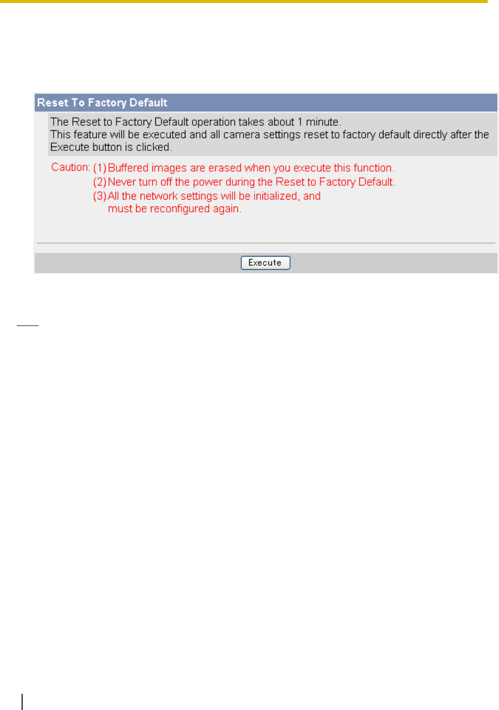
8.9 Resetting the Camera
You can reset all of the camera’s settings to their factory default settings.
1. Click the [Maintenance] tab.
2. On the left side of the screen under [Maintenance], click [Reset to Factory Default].
3. Click [Execute].
•The POWER indicator flashes orange, and then turns off for a few seconds.
Note
•Do not turn off the camera while the camera is being reset. When the lens finishes panning and tilting,
it is safe to turn off the camera.
•When the camera is reset, the following information will be deleted:
–All images buffered in the internal memory
–All alarm logs
–All camera settings (including the user name, password, IP address, subnet mask etc.)
The network connection mode changes to [Automatic Setup]. Reconfigure the camera by referring
to the Setup Guide.
•When the camera is reset, the internal clock will not be reset, but the time format will be set to AM/PM
mode. Change the setting if necessary (see Page 140).
•See Page 211 for a list of the camera’s default settings.
184 Operating Instructions
8.9 Resetting the Camera

Resetting the camera using the FACTORY DEFAULT RESET button
You can also reset all of the camera’s settings to their factory default settings by pressing the FACTORY
DEFAULT RESET button for about one second with a pointed object.
FACTORY DEFAULT RESET
Operating Instructions 185
8.9 Resetting the Camera

9 The [Support] Tab
The [Support] tab can be accessed by all users and provides access to the following pages.
The [Help] page
Displays basic help information.
The [Wireless Help] page (BL-C230 only)
Displays basic help information regarding wireless settings.
The [Product Information] page
Displays a link to the Panasonic Network Camera website (http://panasonic.net/pcc/ipcam/) where you can
view product information.
The [Support Information] page
Displays a link to the Panasonic Network Camera support site (http://panasonic.net/pcc/support/netwkcam/),
where you can view technical information, download the latest firmware, etc.
186 Operating Instructions

10 Using IPv6
Your Panasonic Network Camera supports IPv6 (Internet Protocol Version 6). IPv6 is a next generation
protocol and is expected to eventually replace IPv4, the current standard Internet protocol. As the Internet
continues to expand and more and more IP-compatible devices are being introduced, the number of IP
addresses supported by IPv4 is running out. While IPv4 supports just over 4 billion unique addresses, the
number of addresses supported by IPv6 is virtually unlimited.
Although several Internet Service Providers (ISPs) do not support IPv6 yet, your Network Camera will be ready
as IPv6 services become more widespread.
For more information regarding IPv6, visit http://www.ipv6.org/.
Note
•The following restrictions apply when using the camera in an IPv6-native network.
–Viewnetcam.com service cannot be used
–The Setup Program can be used to search for cameras only (other Setup Program features cannot
be used)
Requirements for accessing the camera using IPv6
The following hardware and software is required to access the camera using IPv6.
•Windows Vista, Windows XP Service Pack 1 or later
•Internet Explorer 6.0 or later
•An IPv6-compatible router
•An IPv6-compatible Internet connection
Subscribe to your Internet Service Provider’s “IPv4/IPv6 Dual-Stack” or “IPv6 over IPv4 Tunneling” service.
•For Internet Explorer 6 users: A subscription to an IPv6-compatible domain name service or Dynamic
DNS service
You cannot access the camera by entering its IPv6 address in your web browser, therefore, you need to
subscribe to an IPv6-compatible domain name service or Dynamic DNS service and configure the camera
to use the Dynamic DNS Service (see Page 104). We recommend using Viewnetcam.com, a Dynamic
DNS service designed for use with Panasonic Network Cameras. For more information about IPv6 access,
ask your ISP about IPv6-compatible services.
Preparations for accessing the camera using IPv6
The following procedures are required before you can access the camera using IPv6.
1. Configure your router for IPv6 (see Page 188).
2. Configure your PC for IPv6 (see Page 189).
3. Configure the camera for IPv6 (see Page 190).
Operating Instructions 187

10.1 Configuring Your Router for IPv6
Refer to your Internet Service Provider and the operating instructions included with your router for information
on configuring the router for IPv6. If outside access (WAN access) is disabled on the router, use the router’s
packet filtering feature to allow the router to receive the desired TCP packets from the WAN side. See the
Panasonic Network Camera website at http://panasonic.net/pcc/support/netwkcam/ for information about the
recommended routers.
188 Operating Instructions
10.1 Configuring Your Router for IPv6

10.2 Configuring Your PC for IPv6
IPv6 is supported by Windows Vista and Windows XP Service Pack 1 or later. If using Windows XP, use the
procedure below to enable your PC for IPv6.
1. Click [Start]®[All Programs]®[Accessories]®[Command Prompt].
2. When the [Command Prompt] is displayed, enter ipv6 install. When installation is complete,
[Succeeded.] will be displayed.
3. Confirm that IPv6 was successfully enabled, enter ipconfig. If IPv6 addresses are displayed, installation
was successful.
For Windows XP Service Pack 2 or later users
If you use Windows XP Service Pack 2 or later, the following procedure is also necessary.
1. Click [Start]®[Control Panel]®[Security Center]®[Windows Firewall]®[Advanced] tab.
2. Click the [Settings...] button under [ICMP].
3. Check [Allow incoming router request], then click [OK].
Operating Instructions 189
10.2 Configuring Your PC for IPv6
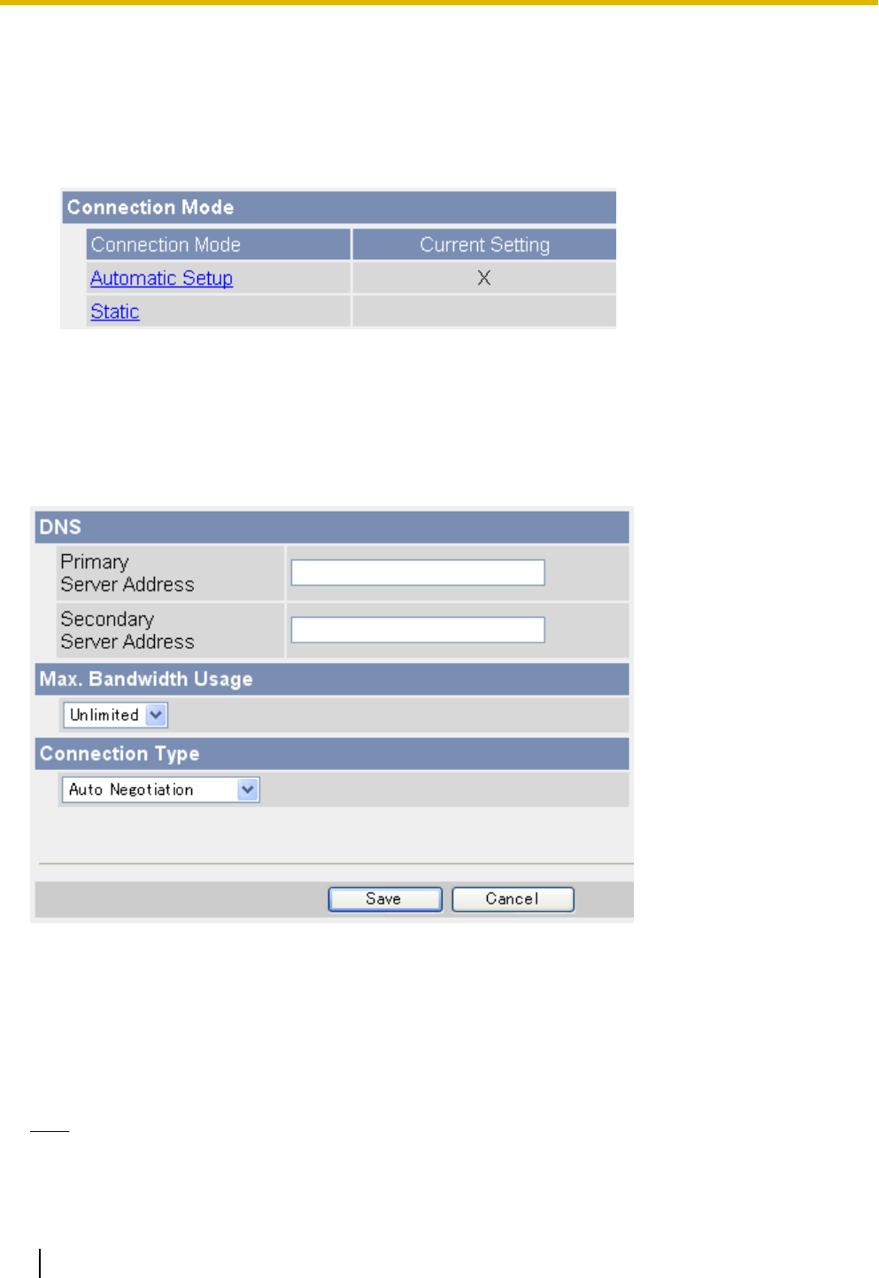
10.3 Configuring Your Camera for IPv6
When the [Connection Mode] on the [Network (IPv6)] page is set to [Automatic Setup], an IPv6 address is
automatically assigned to the camera. To assign a static IPv6 address, follow the procedure below.
1. Click the [Setup] tab.
2. On the left side of the screen under [Basic], click [Network (IPv6)].
3. Select the desired connection mode, then make the appropriate settings as described in this section.
–[Automatic Setup]: The camera is automatically assigned an IPv6 prefix from the IPv6 router, and
produces an original IPv6 address based on the IPv6 prefix.
–[Static]: Allows you to set all network settings manually.
[Automatic Setup]
1. Set the following parameters as desired.
a. Under [DNS], enter the IP addresses of the primary and secondary DNS servers provided by your ISP.
b. Under [Max. Bandwidth Usage], select the maximum bandwidth you want to allow the camera to use.
c. Under [Connection Type], select the appropriate connection type.
•Normally you can leave this setting at [Auto Negotiation].
2. Click [Save].
3. When the [New settings are saved.] message is displayed, click [Restart].
Note
•The current network settings can be confirmed on the [Status] page (see Page 176). You can also
confirm the camera’s IPv6 address using the Setup Program.
190 Operating Instructions
10.3 Configuring Your Camera for IPv6
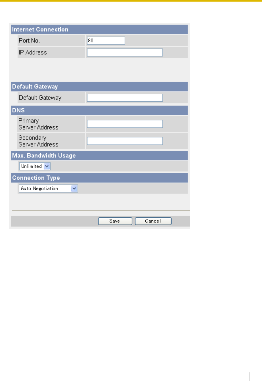
[Static]
1. Set the following parameters as desired.
a. Under [Internet Connection], enter the port number to be assigned to the camera.
•The default port number is 80, however, note that some ISPs do not allow access from the Internet
using port 80. Ask your ISP or network administrator about which port numbers are available for
access over the Internet.
b. Enter the IP address to be assigned to the camera.
•Ask your ISP or network administrator for the correct settings.
c. Under [Default Gateway], enter the IP address of your router or the default gateway IP address provided
by your ISP.
d. Under [DNS], enter the IP addresses of the primary and secondary DNS servers provided by your ISP.
e. Under [Max. Bandwidth Usage], select the maximum bandwidth you want to allow the camera to use.
•This setting is effective for both IPv4 and IPv6 connections.
•Refer to the following file size information when restricting the maximum bandwidth. Note that these
are estimated file sizes for one JPEG image (the actual file size may vary depending on image
quality, image brightness, etc.). To determine the bandwidth required, multiply this number by the
number of accesses (for JPEG images), and multiply the H.264 or MPEG-4 bit rate setting on the
[Video Streaming] page by the number of H.264 or MPEG-4 accesses.
–192 ´ 144: 7 KB (56 Kbit)
–320 ´ 240: 16 KB (128 Kbit)
Operating Instructions 191
10.3 Configuring Your Camera for IPv6

–640 ´ 480: 35 KB (280 Kbit)
f. Under [Connection Type], select the appropriate connection type.
•Normally you can leave this setting at [Auto Negotiation].
•This setting is effective for both IPv4 and IPv6 connections.
2. Click [Save].
3. When the [New settings are saved.] message is displayed, click [Restart].
Note
•The current network settings can be confirmed on the [Status] page (see Page 176). You can also
confirm the camera’s IPv6 address using the Setup Program.
192 Operating Instructions
10.3 Configuring Your Camera for IPv6

10.4 Accessing the Camera in IPv6 Mode
You will need to know the following information to access the camera in IPv6 mode.
For Internet Explorer 6 users:
•The URL assigned to you by the domain name service or Dynamic DNS service you registered the camera
to (e.g., ***.viewnetcam.com).
•The port number of the camera, if it is not 80.
•The user name and password required to access the camera, which were set during camera setup.
For Internet Explorer 7 or Internet Explorer 8 users:
•The camera’s IPv6 address, or the URL assigned to you by the domain name service or Dynamic DNS
service you registered the camera to (e.g., ***.viewnetcam.com).
•The port number of the camera, if it is not 80.
•The user name and password required to access the camera, which were set during camera setup.
Accessing the camera in IPv6 mode
1. Start your PC’s web browser.
2. In the browser’s address bar, enter http:// followed by the host name and port number (if it is not 80)
of the camera, then press [Enter] on the keyboard.
Example: http://***.viewnetcam.com
•If using Internet Explorer 7 or Internet Explorer 8, you can also access the camera by entering
http:// followed by the IPv6 address and port number (if it is not 80) of the camera. Note that the
IPv6 address must be enclosed in brackets as shown below.
Example: http://[****::***:****:****:***]:50000
•If the camera is configured to use HTTPS (see Page 119), enter https:// followed by the host name
and port number of the camera.
3. When the authentication dialog is displayed, enter the user name and password, then click [OK]. The top
page is displayed.
Note
•For general information on accessing the camera, see Page 8.
Operating Instructions 193
10.4 Accessing the Camera in IPv6 Mode
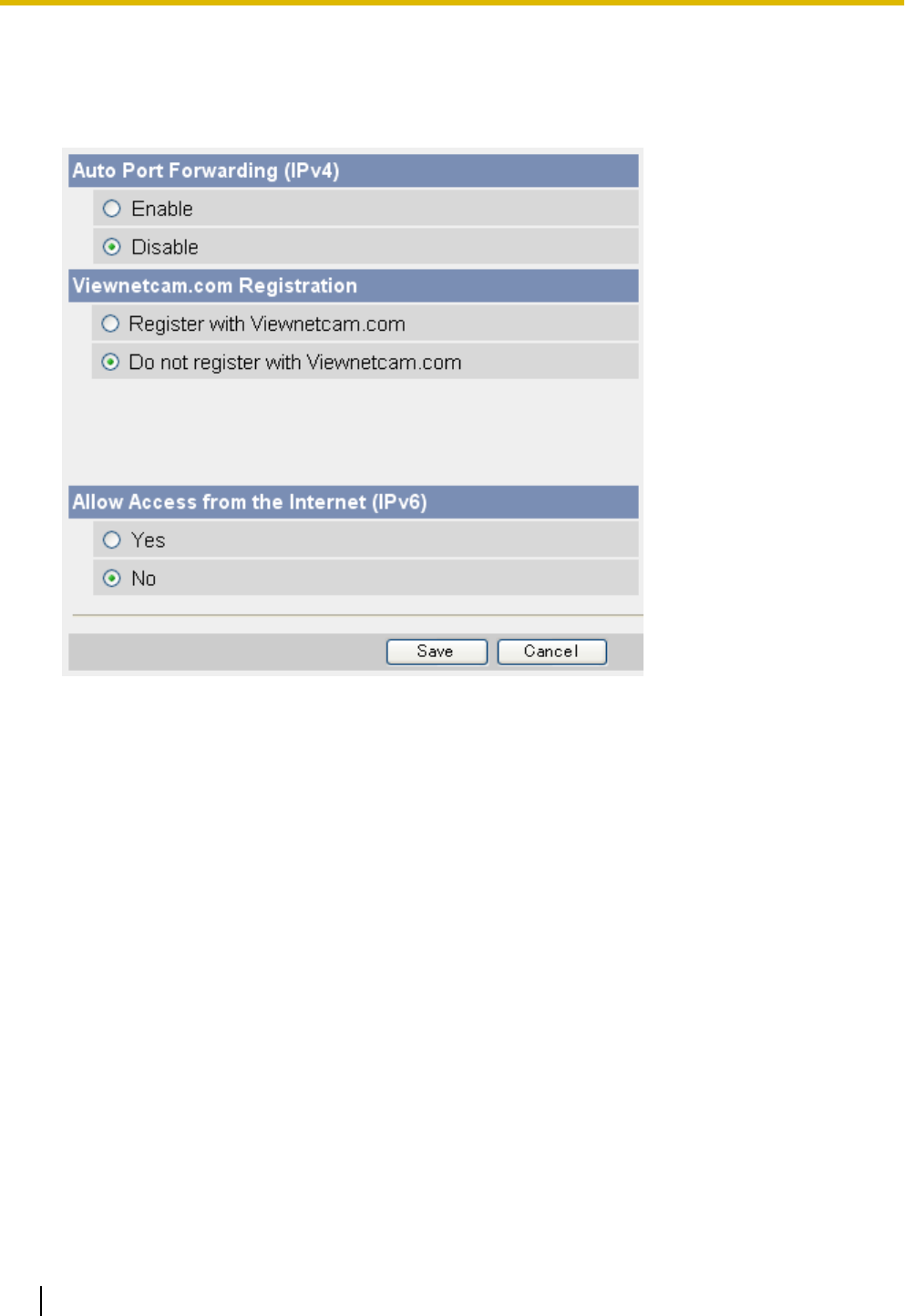
10.5 Allowing IPv6 Access from the Internet
You can configure the camera to allow or restrict IPv6 access from the Internet.
1. Click the [Internet] tab.
2. Under [Allow Access from the Internet (IPv6)], select [Yes] to allow IPv6 access to the camera from the
Internet, or [No] to limit IPv6 access to the camera.
•If [No] is selected, IPv6 access to the camera is only possible from an address of the same prefix as
the camera’s IPv6 address. The camera will not be able to be accessed from the Internet using IPv6.
3. Click [Save].
194 Operating Instructions
10.5 Allowing IPv6 Access from the Internet
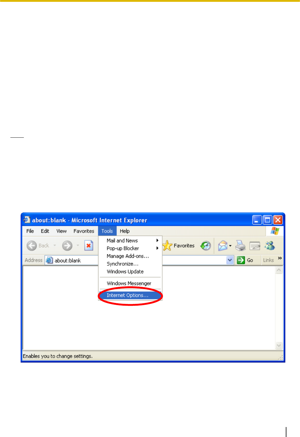
11 PC Settings
11.1 Proxy Server Settings
A proxy server is used to protect computers when connecting to the Internet. If your computer network uses a
proxy server (many corporate networks do; most home networks do not) and you are accessing the camera
from a PC connected to the same LAN as the camera, you may experience the following issues.
–Camera cannot be accessed
–Slow image refresh rate
–Camera images cannot be seen
–Audio features cannot be used
If your network uses a proxy server, we recommend setting your web browser to bypass the proxy server when
accessing the camera from a PC connected to the same LAN as the camera.
Note
•Consult your Internet Service Provider or network administrator to find out if your network uses a proxy
server and consult your network administrator before changing your PC’s proxy server settings.
•The video and audio features cannot be used when the camera is accessed through a proxy server
requiring authentication.
How to bypass the proxy server when accessing the camera
1. Start Internet Explorer.
2. From the [Tools] menu, select [Internet Options...].
Operating Instructions 195
11.1 Proxy Server Settings
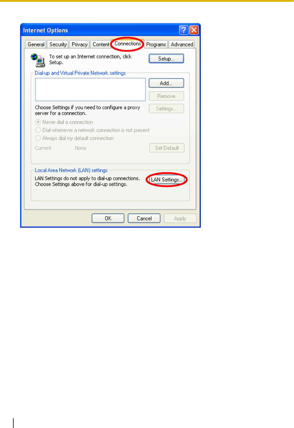
3. Click the [Connections] tab, then click [LAN Settings...].
196 Operating Instructions
11.1 Proxy Server Settings
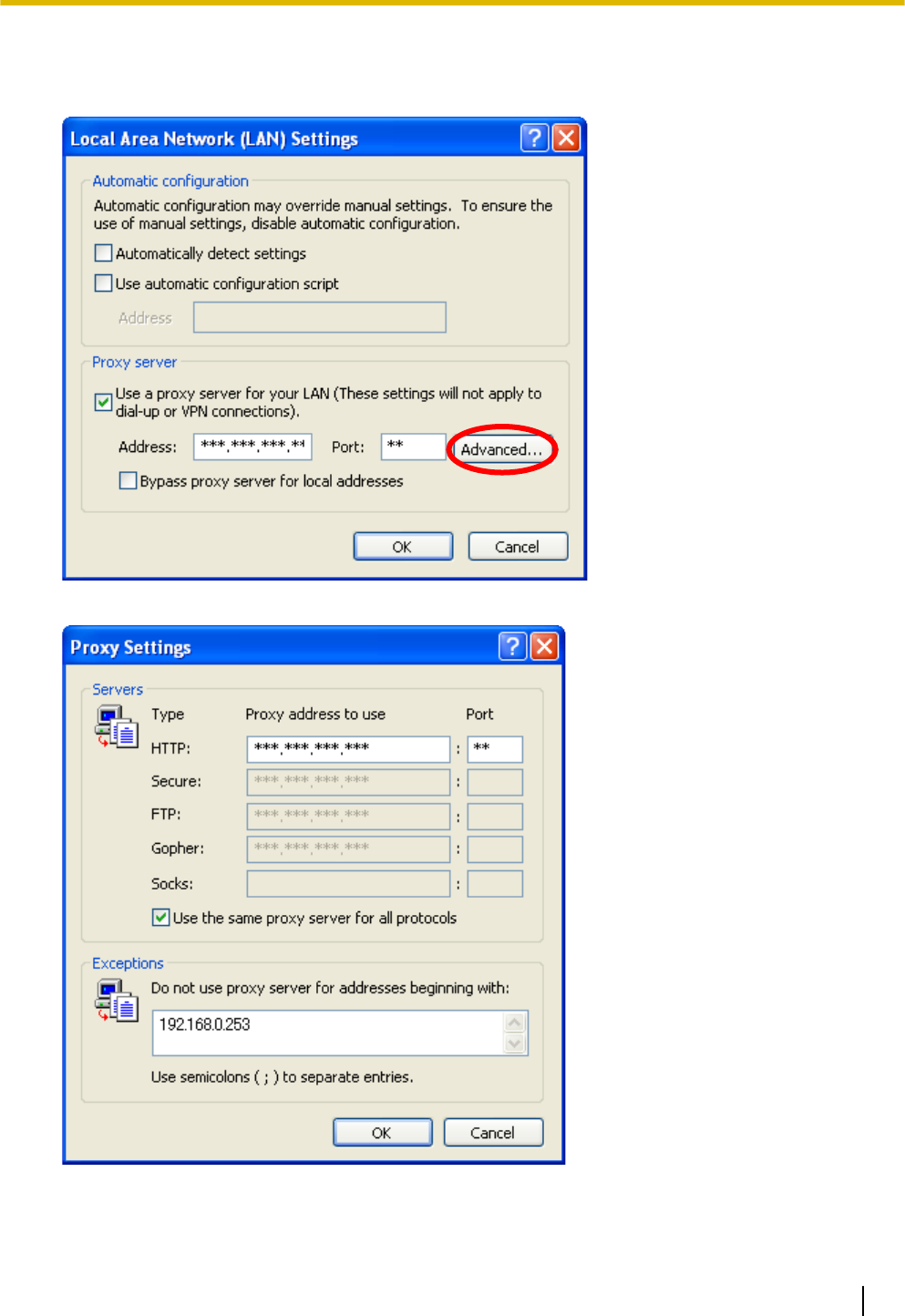
4. If there is a check next to [Use a proxy server for your LAN], click [Advanced...].
•If there is no check next to [Use a proxy server for your LAN], click [Cancel]. You do not need to change
any settings.
5. Enter the camera’s IP address in the field under [Do not use proxy server for addresses beginning with:].
6. Click [OK].
Operating Instructions 197
11.1 Proxy Server Settings

11.2 Creating a Shortcut to the Camera
You can create a shortcut to the camera in your computer’s [My Network Places] folder ([Network] folder when
using Windows Vista) that will be automatically updated even if the camera’s IP address changes. In order to
use this feature, you must first enable the UPnP™ component of Windows using the following procedure.
When using Windows XP (Service Pack 2 or later)
[Start]®([Settings])®[Control Panel]®[Add or Remove Programs]®
[Add/Remove Windows Components]®Select [Networking Services]®[Details]®
Check [Internet Gateway Device Discovery and Control Client] and [UPnP User Interface]®
[OK]®[Next]®Complete
When using previous versions of Windows XP
[Start]®([Settings])®[Control Panel]®[Add or Remove Programs]®
[Add/Remove Windows Components]®Select [Networking Services]®
[Details]®Check [UPnP User Interface]®[OK]®[Next]®Complete
When using Windows Vista
[Start]®[Control Panel]®[Network and Internet]®[Network and Sharing Center]®Click the arrow button to
expand [Network discovery] under [Sharing and Discovery]®Select [Turn on network discovery]®Click
[Apply]®Complete
198 Operating Instructions
11.2 Creating a Shortcut to the Camera

11.3 Changing the Browser’s Temporary Internet
Files Setting
If old images are displayed when you access the camera, change the browser’s temporary Internet files setting
using the following procedure.
When using Internet Explorer 6
Start Internet Explorer®[Tools]®[Internet Options...]®[General] tab®
Click [Settings...] under [Temporary Internet files]®
Check [Every visit to the page] under [Check for newer versions of stored pages:]®
[OK]®[OK]®Complete
When using Internet Explorer 7 or Internet Explorer 8
Start Internet Explorer®[Tools]®[Internet Options]®[General] tab®
Click [Settings] under [Browsing history]®
Check [Every time I visit the webpage] under [Check for newer versions of stored pages:]®
[OK]®[OK]®Complete
Operating Instructions 199
11.3 Changing the Browser’s Temporary Internet Files Setting

11.4 About the MPEG-4 Viewer Program
The MPEG-4 viewer program is an ActiveX Control that is used to play MPEG-4 files within Internet Explorer.
This software is installed automatically the first time you view MPEG-4 videos.
A software license for the MPEG-4 decoder is included with the MPEG-4 viewer program, and the license is
valid for 1 PC. Please read the included End-User License Agreement before installing the viewer program.
When installing the MPEG-4 viewer program on additional PCs, please purchase additional licenses (Model
No. BB-HCA5A for BL-C210A/BL-C230A, BB-HCA5CE for BL-C210CE/BL-C210E/BL-C230CE/BL-C230E).
Uninstalling the MPEG-4 viewer program
Follow the procedure below to uninstall the MPEG-4 viewer program.
When using Windows XP
1. Confirm that Internet Explorer is not running®Start Internet Explorer®[Tools]®
[Internet Options...]®[General] tab®Click [Settings...] under [Browsing history] ([Temporary Internet files]
for Internet Explorer 6)®Click [View Objects...]®
Right-click on [pmpeg4camV4 Class]®[Remove]®[Yes]
2. Open the [ocx] folder on the CD-ROM®Open the [MPEG-4] folder®Double-click [uninstall.bat]
When using Windows Vista
1. Confirm that Internet Explorer is not running®Start Internet Explorer®[Tools]®
[Internet Options...]®[Programs] tab®Click [Manage add-ons]®
for Internet Explorer 8
Select [Show:]®[Downloaded controls]®Right-click on [pmpeg4camV4 Class]®[More
Information]®Click [Remove]
for Internet Explorer 7
Select [Show:]®[Downloaded ActiveX Controls (32bit)]®Click [pmpeg4camV4 Class]®Click [Delete]
2. Open the [ocx] folder on the CD-ROM.
3. Copy the [MPEG-4] folder to the PC.
4. Click [Start]®[All Programs]®[Accessories].
5. Right-click on [Command Prompt], then click [Run as administrator].
6. Using the Command Prompt, navigate to the [MPEG-4] folder and execute [uninstall.bat].
Note
•When using Windows Vista, you must be logged into your PC as a user with Administrator privileges.
For more information, open the [ocx] folder on the CD-ROM, then open the [MPEG-4] folder on the
CD-ROM and double-click [ReadmeEng.txt].
•Refer to the Panasonic Network Camera support site (http://panasonic.net/pcc/support/netwkcam/) for
more information.
200 Operating Instructions
11.4 About the MPEG-4 Viewer Program

11.5 About the H.264 Viewer Program
The H.264 viewer program is an ActiveX Control that is used to play H.264 files within Internet Explorer. This
software is installed automatically the first time you view H.264 videos.
A software license for the H.264 decoder is included with the H.264 viewer program, and the license is valid
for 1 PC. Please read the included End-User License Agreement before installing the viewer program. When
installing the H.264 viewer program on additional PCs, please purchase additional licenses (Model No.
BB-HCA8A for BL-C210A/BL-C230A, BB-HCA8CE for BL-C210CE/BL-C210E/BL-C230CE/BL-C230E).
Uninstalling the H.264 viewer program
Follow the procedure below to uninstall the H.264 viewer program.
When using Windows XP
1. Confirm that Internet Explorer is not running®Start Internet Explorer®[Tools]®
[Internet Options...]®[General] tab®Click [Settings...] under [Browsing history] ([Temporary Internet files]
for Internet Explorer 6)®Click [View Objects...]®
Right-click on [PccCamActXCtrl Control]®[Remove]®[Yes]
2. Open the [ocx] folder on the CD-ROM®Open the [H.264] folder®Double-click [uninstall.bat]
When using Windows Vista
1. Confirm that Internet Explorer is not running®Start Internet Explorer®[Tools]®
[Internet Options...]®[Programs] tab®Click [Manage add-ons]®
for Internet Explorer 8
Select [Show:]®[Downloaded controls]®Right-click on [PccCamActXCtrl Control]®[More
Information]®Click [Remove]
for Internet Explorer 7
Select [Show:]®[Downloaded ActiveX Controls (32bit)]®Click [PccCamActXCtrl Control]®Click [Delete]
2. Open the [ocx] folder on the CD-ROM.
3. Copy the [H.264] folder to the PC.
4. Click [Start]®[All Programs]®[Accessories].
5. Right-click on [Command Prompt], then click [Run as administrator].
6. Using the Command Prompt, navigate to the [H.264] folder and execute [uninstall.bat].
Note
•When using Windows Vista, you must be logged into your PC as a user with Administrator privileges.
For more information, open the [ocx] folder on the CD-ROM, then open the [H.264] folder on the
CD-ROM and double-click [ReadmeEng.txt].
•Refer to the Panasonic Network Camera support site (http://panasonic.net/pcc/support/netwkcam/) for
more information.
Operating Instructions 201
11.5 About the H.264 Viewer Program

12 Using the Setup Program
The Setup Program, found on the included CD-ROM, can be used to:
–Find cameras on the LAN and confirm information (IP address, firmware version, status, etc.) as needed
(see Page 202).
–Configure a camera’s network settings (see Page 202).
–Update a camera’s firmware (see Page 203).
–Save a configuration file of a camera’s settings to your PC (see Page 203).
–Restore the settings saved in a configuration file on your PC (see Page 204).
Note
•Although the above can be performed by accessing a camera directly, using the Setup Program is
convenient when you want to configure several cameras because there is no need to access each
camera individually with your web browser.
•When the camera is connected in IPv6 mode, the Setup Program can be used only to find and confirm
cameras on the LAN (other Setup Program features are not available).
•If you are using firewall or antivirus software on your PC, the Setup Program may not be able to find
any cameras on your network. If you cannot disable your firewall or antivirus software, you can find the
camera by entering its MAC address. Click [Search by MAC Address], then enter the camera’s MAC
address. (The MAC address is printed on a label affixed to the camera.)
•If the Setup Program fails to set up the camera, temporarily disable any antivirus software.
Finding cameras on the LAN
1. Insert the included CD-ROM into the CD-ROM drive of your PC.
•The Setup Program starts. If the program does not start, double-click Setup.exe found on the CD-ROM.
2. Click [Search for Cameras].
3. Wait for the Setup Program to find all cameras on the network and display their information.
•If the desired camera is not displayed, confirm it is turned on and connected to the network.
•If the desired camera is not displayed, you can find the camera by entering its MAC address. Click
[Search by MAC Address], then enter the camera’s MAC address. (The MAC address is printed on a
label affixed to the camera.)
4. Confirm the information as needed.
Configuring a camera’s network settings
1. Find the camera on the LAN (see Page 202).
2. Select the desired camera.
3. Click [Network Settings].
•If more than 20 minutes have passed since the selected camera was turned on, you cannot configure
the camera. Turn off the camera, then turn it on again. This restriction does not apply to cameras which
have not been configured yet or have been reset to their factory default settings.
4. Change the camera name as desired (max. 15 characters).
•See Page 206 for a list of valid characters. Note that [Space], ["], ['], [&], [<], and [>] cannot be entered.
5. Enter the port number to be assigned to the camera.
•The default port number is 80, however, note that some ISPs do not allow access from the Internet
using port 80. Ask your ISP or network administrator about which port numbers are available for access
over the Internet.
•Do not use the following port numbers:
–20 and 21: used for FTP
–23: used for Telnet
202 Operating Instructions

–25: used for SMTP
–53: used for DNS
–110: used for POP3
–443: used for HTTPS
–4000: used for ICQ
–6661–6667: used for IRC
•If you are connecting multiple cameras and plan on using port forwarding to allow Internet access to
the cameras, assign a different port number to each camera. We recommend using port numbers in
the 50000–50050 range.
6. Select the desired connection mode, and enter the appropriate settings. See Page 113 for details about
each setting.
–[Automatic Setup]: Configures the camera automatically based on your network’s settings.
–[Specify an IP Address]: Allows you to assign a static IP address. Refer to your ISP or network
administrator for more information.
a. Specify an IP address corresponding to your network’s settings.
b. Specify the subnet mask of your network.
c. Enter the default gateway (the IP address of your router).
d. Enter the IP address of the DNS server(s).
e. Specify the maximum bandwidth the camera is allowed to use.
–[DHCP]: Allows the camera to be configured automatically by your network’s DHCP server (usually
your router). Refer to your ISP or network administrator for more information.
a. Enter the host name if required by your ISP or network administrator.
b. Enter the default gateway if required by your ISP or network administrator.
c. Enter the IP address of the DNS server(s). Refer to your ISP or network administrator for more
information.
d. Specify the maximum bandwidth the camera is allowed to use.
7. Click [Save].
8. Follow the on-screen prompts.
Updating a camera’s firmware
1. Download the latest firmware from the Panasonic Network Camera website
(http://panasonic.net/pcc/support/netwkcam/) and save it on your PC.
2. Insert the included CD-ROM into the CD-ROM drive of your PC.
•The Setup Program starts. If the program does not start, double-click Setup.exe found on the CD-ROM.
3. Click [Update Firmware]. A dialog prompts you to specify the location of the firmware file.
4. Select the firmware file you downloaded from the Panasonic Network Camera website and click [Open].
5. Select the camera you would like to update.
•Only cameras which are compatible with the selected firmware file are displayed.
•You can select multiple cameras if desired.
6. Enter the administrator user name and password when prompted, then click [OK].
7. Click [Execute].
•[Firmware updated successfully.] is displayed when the firmware has been updated.
8. Click [Save Log] to save a log of the firmware revision.
9. Click [OK] when finished.
Saving settings in a configuration file
1. Insert the included CD-ROM into the CD-ROM drive of your PC.
•The Setup Program starts. If the program does not start, double-click Setup.exe found on the CD-ROM.
2. Click [Save Settings to PC/Save Settings to Camera].
Operating Instructions 203

3. Select the desired camera, enter the camera’s administrator user name and password when prompted,
then click [OK].
4. Click [Save Settings to PC].
5. Specify a location to save the file, then click [Save].
6. When [Settings were saved on the PC.] is displayed, click [OK].
Note
•Buffered images are not saved in the configuration file.
•The configuration file’s extension (.dat) must not be changed. If you change it, the saved settings cannot
be restored.
•The configuration file is encrypted. Do not open it using a text editor or other software, otherwise it may
become corrupted. If the configuration file becomes corrupted it cannot be used to restore camera
settings.
•If you save a configuration file and then update the camera’s firmware later, the configuration file may
not be able to be restored properly. If you regularly save a configuration file of the cameras settings,
remember to save a configuration file after you update the camera’s firmware.
Restoring settings from a configuration file
1. Insert the included CD-ROM into the CD-ROM drive of your PC.
•The Setup Program starts. If the program does not start, double-click Setup.exe found on the CD-ROM.
2. Click [Save Settings to PC/Save Settings to Camera].
3. Click [Save Settings to Camera]. A dialog prompts you to specify the location of the saved configuration
file.
4. Specify the configuration file and click [Open].
5. Select the desired camera, enter the camera’s administrator user name and password when prompted,
then click [OK].
6. Click [Execute]. A dialog displays the status.
7. After the settings have been restored to the camera, the camera will restart automatically.
8. Click [OK] when finished.
Note
•Network settings and the administrator user name and password are not changed when you restore a
configuration file using the Setup Program.
204 Operating Instructions

13 Technical Information
13.1 Cleaning the Camera
For best performance, we recommend cleaning the camera periodically. Turn the camera off before cleaning
it.
Cleaning the main unit
Clean the main unit with a dry and soft cloth.
Note
•Do not use alcohol, polishing powder, cleanser, benzine, thinner, wax, petroleum products, pesticides,
glass cleaners, hair spray, or hot water when cleaning the camera, as they may cause a change in the
shape or color of the camera.
•Do not directly touch the lens cover. Fingerprints may cause the image to be out of focus.
•If the built-in sensor has dust on it, it may not make detections properly. Keep the built-in sensor clean.
Operating Instructions 205
13.1 Cleaning the Camera

13.2 ASCII Character Table
[Space] 0 @ P ` p
! 1 A Q a q
" 2 B R b r
# 3 C S c s
$ 4 D T d t
% 5 E U e u
& 6 F V f v
' 7 G W g w
( 8 H X h x
) 9 I Y i y
* : J Z j z
+ ; K [ k {
, < L \ l |
- = M ] m }
. > N ^ n ~
/ ? O _ o
206 Operating Instructions
13.2 ASCII Character Table

13.3 Internal Memory Capacity for Buffered Images
The camera’s internal memory can buffer images according to the table below.
Note
•All values are approximate.
•H.264 images cannot be buffered to the camera’s internal memory.
JPEG images (videos and still images)
Resolution Specification Snapshot
Image Quality
Favor Clarity Standard Favor Motion
640 ´ 480
File Size 50 KB 50 KB 35 KB 27 KB
No. of Images (Saved to PC) 360 520 680
320 ´ 240
File Size 25 KB 25 KB 16 KB 10 KB
No. of Images (Saved to PC) 730 1160 1880
192 ´ 144
File Size 10 KB 10 KB 7 KB 5 KB
No. of Images (Saved to PC) 1880 2710 3850
Note
•The maximum number of images that can be buffered depends on image resolution and image quality.
MPEG-4 videos
For information about MPEG-4 image capacity, see the Panasonic Network Camera support site at
http://panasonic.net/pcc/support/netwkcam/.
Note
•The maximum amount of video that can be buffered depends on image resolution, network bandwidth,
and the frame rate and bit rate set for the streaming method.
Operating Instructions 207
13.3 Internal Memory Capacity for Buffered Images

13.4 Information About Streaming Format
The image refresh rate and resolution settings that are available to users are determined by the [Streaming
Format] setting on the [Video Streaming] page (see 5.8 Changing Video Streaming Settings). Refer to the
table below and set this parameter based on the refresh rate and resolution you wish to be available to camera
users.
[Streaming Format] Setting
Available
[Refresh Rate]
Settings
Available
[Resolution]
Settings
H.264 (640 ´ 480, 320 ´ 240)
MJPEG (640 ´ 480, 320 ´ 240, 192 ´ 144)
H.264 640 ´ 480
320 ´ 240
MJPEG 640 ´ 480
320 ´ 240
192 ´ 144
MPEG-4 (640 ´ 480, 320 ´ 240, 192 ´ 144)
MJPEG (640 ´ 480, 320 ´ 240, 192 ´ 144)
MPEG-4 640 ´ 480
320 ´ 240
192 ´ 144
MJPEG 640 ´ 480
320 ´ 240
192 ´ 144
Note
•If the [Streaming Format] setting on the [Video Streaming] page is changed, the camera must be
restarted in order for the new settings to take effect. All images buffered in the internal memory are
deleted when the camera is restarted.
•If using Network Camera Recorder software, a blue screen will be displayed if the software tries to
access camera images with a refresh rate and resolution that are not supported according to the
[Streaming Format] setting, as described above.
•Only 320 ´ 240 and 192 ´ 144 images are available on the multi camera screen.
208 Operating Instructions
13.4 Information About Streaming Format

13.5 Feature Limitations Based on Image Format
Certain features are limited based on the image format (H.264, MPEG-4, and MJPEG) as explained below.
Image buffer and transfer
Image Format Resolution Image Buffer Image Transfer
H.264 640 ´ 480 ´ ´
320 ´ 240 ´ ´
MPEG-4 640 ´ 480 Timer only ´
320 ´ 240 Timer only ´
192 ´ 144 Timer only ´
MJPEG 640 ´ 480 ü ü
320 ´ 240 ü ü
192 ´ 144 ü ü
ü=Available
´=Not available
Operating Instructions 209
13.5 Feature Limitations Based on Image Format

13.6 Comparing Color Night View and Software Color
Night View
When camera images are dark, there are two features you can use to brighten camera images: Color Night
View (Page 142) and Software Color Night View (Page 41). The differences between these features are
described below.
Color Night View Software Color Night View
Refresh Rate Decreases when subject is dark Decreases when subject is dark
depending on computer performance
CPU Usage Is not affected Increases CPU usage
User Control Is either enabled or disabled for all users Is enabled or disabled by each user on
their computers
Resolution Has no limitations Has no limitations
Activation Is activated when subject is dark (when
enabled)
Is activated when subject is dark (when
enabled)
Other
Limitations
Image may blur when dark May not perform as expected when frame
rate decreases
Note
•When viewing H.264 or MPEG-4 images, the computer’s performance may not be adequate to use
software color night view, and images may break up as a result. In this case, turn off software color
night view and try using the camera’s color night view mode feature (see Page 142).
210 Operating Instructions
13.6 Comparing Color Night View and Software Color Night View

13.7 Default Setting List
Single
Parameter Default Value Range
Precise Off On, Off
Pan/Tilt Range Pan: -41° – +41°
Tilt: -32° – +10°
Pan: -41° – +41°
Tilt: -32° – +10°
Preset 1.UpperLeft
2.UpperRight
3.LowerLeft
4.LowerRight
Presets 1–8, Home
Position, Sensor,
Alarm1, Alarm2
Brightness STD 9 levels
Backlight Off On, Off
White Balance Auto Auto, Indoor,
Fluorescent (White),
Fluorescent (Daylight),
Outdoor, Hold
BL-C230 only:
Output
– Open
Short
Refresh Rate MJPEG H.264, MPEG-4,
MJPEG, 3 s, 5 s, 10 s,
30 s, 60 s
Resolution 320 ´ 240 640 ´ 480, 320 ´ 240,
192 ´ 144
Image Quality Standard Favor Clarity,
Standard, Favor
Motion
Streaming Method Auto Auto, Multicast,
Unicast, HTTP
Multi
Parameter Default Value Range
Layout 4 Screens 4 Screens, 9 Screens,
16 Screens
View Type 1–4 1–4, 5–8, 9–12, 13–16
Refresh Rate MJPEG H.264, MPEG-4,
MJPEG, 3 s, 5 s, 10 s,
30 s, 60 s
Resolution 320 ´ 240 320 ´ 240, 192 ´ 144
Operating Instructions 211
13.7 Default Setting List

Network (IPv4)
Parameter Default Value Range
Connection Mode Connection Mode BL-C210A/
BL-C230A:
DHCP
BL-C210CE/
BL-C210E/
BL-C230CE/
BL-C230E:
Automatic Setup
Automatic Setup,
Static, DHCP
Proxy Server Settings Address – –
Port No. 8080 1–65535
Login ID – –
Password – –
Network Configuration
from Setup Program
Network Configuration from
Setup Program (Available for
Static and DHCP connection
only)
Enable Enable, Disable
Internet Connection Port No. (Available for Static
and DHCP connection only)
80 1–65535
IP Address (Available for
Static connection only)
192.168.0.253 –
Subnet Mask (Available for
Static connection only)
255.255.255.0 –
Host Name (Available for
DHCP connection only)
– –
Default Gateway Default Gateway (Available
for Static and DHCP
connection only)
– –
DNS Primary Server Address
(Available for Static and
DHCP connection only)
– –
Secondary Server Address
(Available for Static and
DHCP connection only)
– –
Max. Bandwidth Usage Max. Bandwidth Usage
(Mbps)
Unlimited Unlimited, 0.1, 0.2, 0.3,
0.5, 1, 2, 3 Mbps
Connection Type Connection Type Auto Negotiation Auto Negotiation, 100
Mbps/Full Duplex, 100
Mbps/Half Duplex, 10
Mbps/Full Duplex, 10
Mbps/Half Duplex
212 Operating Instructions
13.7 Default Setting List

Network (IPv6)
Parameter Default Value Range
Connection Mode Connection Mode Automatic Setup Automatic Setup,Static
Internet Connection Port No. (Available for Static
connection only)
80 1–65535
IP Address (Available for
Static connection only)
– –
Default Gateway Default Gateway (Available
for Static connection only)
– –
DNS Primary Server Address – –
Secondary Server Address – –
Max. Bandwidth Usage Max. Bandwidth Usage
(Mbps)
Unlimited Unlimited, 0.1, 0.2, 0.3,
0.5, 1, 2, 3 Mbps
Connection Type Connection Type Auto Negotiation Auto Negotiation, 100
Mbps/Full Duplex, 100
Mbps/Half Duplex, 10
Mbps/Full Duplex, 10
Mbps/Half Duplex
HTTPS
Parameter Default Value Range
HTTPS Use HTTP Use HTTPS, Use
HTTP
Certificate Information Camera IP Address or Host
Name
– –
Wireless (BL-C230 Only)
Parameter Default Value Range
Wireless Configuration SSID NetCam**** –
Communication mode 802.11b/g 802.11b, 802.11b/g,
802.11g exclusive
Operating Instructions 213
13.7 Default Setting List

Parameter Default Value Range
Encryption Cipher No encryption No encryption, WEP,
WPA-PSK (TKIP),
WPA2-PSK (AES)
WEP Key 1–4
(for WEP encryption)
– HEX,10characters
64bit
HEX,26characters
128bit
HEX,32characters
152bit
ASCII 5characters
64bit
ASCII13characters
128bit
ASCII16characters
152bit
Network Key
(for WPA-PSK (TKIP) or
WPA2-PSK (AES)
encryption)
– HEX, 64 Characters
ASCII, 8 to 63
Characters
UPnP
Parameter Default Value Range
Auto Port Forwarding Disable Enable, Disable
BL-C210CE/BL-C210E/BL-C230CE/BL-C230E only:
Display Shortcut Icon in My Network Places
Enable Enable, Disable
DynamicDNS
Parameter Default Value Range
DynamicDNS Disable Viewnetcam.com,
User-specified
DynamicDNS, Disable
User-specified
DynamicDNS
DynamicDNS Server URL – –
Updating time 10 min At the time of starting,
10 min, 30 min, 1 h, 3
h, 6 h, 12 h, 24 h
Input User Name and
Password
User Name – –
Password – –
214 Operating Instructions
13.7 Default Setting List

Parameter Default Value Range
Viewnetcam.com
configuration
Updating time 60 min 10 min, 20 min, 30 min,
40 min, 50 min, 60 min
Global IP Address Notification Method Normal Normal, Advanced
Date and Time
Parameter Default Value Range
Time Setting Date – –
Format AM/PM AM/PM, 24H
Time – –
Automatic Time
Adjustment
Enable Not enabled –
NTP Server Address or Host
Name
– –
Time Zone BL-C210A/
BL-C230A:
GMT -05:00 Eastern
Time
BL-C210CE/
BL-C210E/
BL-C230CE/
BL-C230E:
GMT 00:00 Western
Europe Time
–
Adjust Clock for Daylight
Saving Time/Summer Time
Enable Not enabled –
Start Day BL-C210A/
BL-C230A:
Mar Second Sunday 2
AM
BL-C210CE/
BL-C210E/
BL-C230CE/
BL-C230E:
Mar Last Sunday 1 AM
–
End Day BL-C210A/
BL-C230A:
Nov First Sunday 2 AM
BL-C210CE/
BL-C210E/
BL-C230CE/
BL-C230E:
Oct Last Sunday 1 AM
–
Operating Instructions 215
13.7 Default Setting List

Camera
Parameter Default Value Range
AC Power Source Frequency BL-C210A/
BL-C230A:
60 Hz
BL-C210CE/
BL-C210E/
BL-C230CE/
BL-C230E:
50 Hz
50 Hz, 60 Hz
Return to Specified Position Time Do not move Do not move, 10 s, 20
s, 30 s, 1 min, 5 min, 10
min, 30 min, 1 h
Specified Position Home Position Home Position,
Sensor, Alarm No.1,
Alarm No.2, Presets 1–
8
Shutter Speed/Color Night View BL-C210A/
BL-C230A:
Shutter Speed 1/30 s
BL-C210CE/
BL-C210E/
BL-C230CE/
BL-C230E:
Shutter Speed 1/25 s
50 Hz:
1/25 s, 1/50 s, 1/100 s,
Color Night View
60 Hz:
1/30 s, 1/60 s, 1/120 s,
Color Night View
Audio
Parameter Default Value Range
Input Enable Enable, Disable
Camera Microphone Sensitivity Normal Very Low, Low,
Normal, High
Mute during Pan/Tilt Enable Enable, Disable
Video Streaming
Parameter Default Value Range
Streaming Format BL-C210A/
BL-C230A:
H.264/MJPEG
BL-C210CE/
BL-C210E/
BL-C230CE/
BL-C230E:
MPEG-4/MJPEG
H.264/MJPEG,
MPEG-4/MJPEG
216 Operating Instructions
13.7 Default Setting List

Parameter Default Value Range
Max. No. of HTTP Sessions
(When [Streaming Format] is
set to H.264/MJPEG)
H.264 2 0–2
MJPEG 3 0–5
Max. No. of HTTPS
Sessions
(When [Streaming Format] is
set to H.264/MJPEG)
H.264 2 0–2
MJPEG 3 0–5
Max. No. of HTTP Sessions
(When [Streaming Format] is
set to MPEG-4/MJPEG)
MPEG-4 3 0–4
MJPEG 5 0–10
Max. No. of HTTPS
Sessions
(When [Streaming Format] is
set to MPEG-4/MJPEG)
MPEG-4 2 0–2
MJPEG 3 0–5
H.264 Max. Frame Rate 640 ´ 480 30 Frames/Sec. 5, 10, 15, 30 frames/
sec.
320 ´ 240 30 Frames/Sec. 5, 10, 15, 30 frames/
sec.
H.264 Bit Rate 640 ´ 480 512 Kbps–2048 Kbps 512, 768, 1024, 1536,
2048 Kbps
320 ´ 240 64 Kbps–1024 Kbps 64, 128, 192, 256, 384,
512, 768, 1024 Kbps
MPEG-4 Max. Frame Rate 640 ´ 480 30 Frames/Sec. 5, 10, 15, 30 frames/
sec.
320 ´ 240 30 Frames/Sec. 5, 10, 15, 30 frames/
sec.
192 ´ 144 30 Frames/Sec. 5, 10, 15, 30 frames/
sec.
MPEG-4 Bit Rate 640 ´ 480 192 Kbps–2048 Kbps 192, 256, 384, 512,
768, 1024, 1536, 2048
Kbps
320 ´ 240 64 Kbps–1024 Kbps 64, 128, 192, 256, 384,
512, 768, 1024 Kbps
192 ´ 144 32 Kbps–512 Kbps 32, 64, 128, 192, 256,
384, 512 Kbps
RTSP Port No. 554 1–65535
RTP Port No. 33000 2–65400 (must be an
even number)
Multicast Multicast settings screen is
displayed.
Not checked –
Packet Availability Time TTL 5 1–255
Operating Instructions 217
13.7 Default Setting List

Parameter Default Value Range
Multicast (IPv4) Use Not checked –
Address 231.244.244.241 –
MPEG-4 Port No. 30000–30006 2000–65520 (must be
an even number)
H.264 Port No. 30040–30046 2000–65520 (must be
an even number)
Audio Port No. 30020 2000–65520 (must be
an even number)
Multicast (IPv6) Use Not checked –
Address ff1e::0010 –
MPEG-4 Port No. 30100–30106 2000–65520 (must be
an even number)
H.264 Port No. 30140–30146 2000–65520 (must be
an even number)
Audio Port No. 30120 2000–65520 (must be
an even number)
Administrator
Parameter Default Value Range
General Authentication Do not permit access
from guest users
Permit access from
guest users, Permit
access from guest
users (mobile only), Do
not permit access from
guest users
User Name – –
Password – –
Retype Password – –
General User
Parameter Default Value Range
User ID List – –
User Name – –
Password – –
Retype Password – –
218 Operating Instructions
13.7 Default Setting List

Parameter Default Value Range
Video Display Time Not permitted Not permitted,
Unlimited, 10 s, 30 s, 1
min, 5 min, 10 min, 30
min, 60 min
Refresh Rate 3 s 3 s, 5 s, 10 s, 30 s, 60
s
Access Level All unchecked –
Guest User
Parameter Default Value Range
Video Display Time Not permitted Not permitted,
Unlimited, 10 s, 30 s, 1
min, 5 min, 10 min, 30
min, 60 min
Refresh Rate 3 s 3 s, 5 s, 10 s, 30 s, 60
s
Access Level All unchecked –
Trigger
Parameter Default Value Range
Trigger Setting Enable Image Buffer/Transfer Not enabled –
Trigger No. 1: Motion
Detection
No. 2–5: Timer
Timer, Sensor, Alarm1,
Alarm2, Motion
Detection, Sound
Detection
Alarm enable condition Rising: GND to Open
(High).
Rising: GND to Open
(High).
Falling: Open (High) to
GND.
Time Days All days checked –
Active Time of Trigger Always Always, specified time
Image Setting Format JPEG JPEG, MPEG-4
Image Resolution 320 ´ 240 640 ´ 480, 320 ´ 240,
192 ´ 144
Image Quality Standard Favor Clarity,
Standard, Favor
Motion
Operating Instructions 219
13.7 Default Setting List

Parameter Default Value Range
Lens Position When
Triggered
When triggered, Do not move Do not move, Home
Position, Sensor,
Alarm No.1, Alarm No.
2, Presets 1–8
BL-C230 only:
External Output
Control Time None None, 1 s, 3 s, 5 s, 10
s, 30 s, 1 min, 3 min, 5
min, 10 min, 30 min,
When Recording
Image Buffer Frequency (for
timer triggers)
Image Buffer Frequency No. 1: Buffer 5 images
every 1 second
No. 2–5: Buffer 1
image every 1 second
1 image every hour–30
images every second
Image Buffer Frequency (for
sensor, alarm, and detection
triggers)
Enable Pre-trigger Image
Buffer
No. 1: Enabled
No. 2–5: Not enabled
–
Image Buffer Frequency No. 1: Buffer 5 images
every 1 second, total of
5 images
No. 2–5: Buffer 1
image every 1 second,
total of 1 image
1 image every minute–
30 images every
second. Total 1–600
images.
Enable Post-trigger Image
Buffer
Enabled –
Image Buffer Frequency No. 1: Buffer 5 images
every 1 second, total of
20 images
No. 2–5: Buffer 1
image every 1 second,
total of 1 image
1 image every minute–
30 images every
second. Total 1–1500
images.
Sensor deactivation time
setting
Sensor deactivation time None None, 10 s, 30 s, 1 min,
3 min, 5 min, 10 min
Transfer Method Transfer Method No. 1: No Transfer,
Memory Overwrite
No. 2–5: No Transfer,
No Memory Overwrite
No Transfer, No
Memory Overwrite
No Transfer, Memory
Overwrite
FTP
E-mail
HTTP
Send Notification When
Triggered
Send Notification When
Triggered
Disable Disable, Send E-mail
Notification, Send
HTTP Notification
220 Operating Instructions
13.7 Default Setting List

Parameter Default Value Range
FTP Server IP Address or Host
Name
– –
Port No. 21 1–65535
Login ID – –
Password – –
Login Timing Every Time Every Time, One Time
Upload File Name – –
Overwrite setting Overwrite File Overwrite File, Save as
New File with Time
Stamp
Data Transfer Method Passive Mode Passive Mode, Active
Mode
E-mail Transfer SMTP Server IP Address or
Host Name
– –
Port No. 25 1–65535
Reply E-mail Address – –
Destination E-mail Address 1 – –
Destination E-mail Address 2 – –
Destination E-mail Address 3 – –
Subject – –
Text – –
How to authenticate No authentication Checked No authentication,
POP before SMTP
authentication, SMTP
authentication
SSL Not use Use, Not use
POP before SMTP
authentication
POP3 Server IP Address or
Host Name
– –
Port No. 110 1–65535
Login ID – –
Password – –
SMTP authentication Login ID – –
Password – –
Operating Instructions 221
13.7 Default Setting List

Parameter Default Value Range
HTTP Host Name – –
Port No. 80 1–65535
Login ID – –
Password – –
Upload File Name – –
Overwrite setting Overwrite File Overwrite File, Save as
New File with Time
Stamp
E-mail Notification When
Triggered
SMTP Server IP Address or
Host Name
– –
Port No. 25 1–65535
Reply E-mail Address – –
Destination E-mail Address 1 – –
Destination E-mail Address 2 – –
Destination E-mail Address 3 – –
Subject – –
Text – –
How to authenticate No authentication Checked No authentication,
POP before SMTP
authentication, SMTP
authentication
SSL Not use Use, Not use
POP before SMTP
authentication
POP3 Server IP Address or
Host Name
– –
Port No. 110 1–65535
Login ID – –
Password – –
SMTP authentication Login ID – –
Password – –
HTTP Notification Host Name – –
Port No. 80 1–65535
Login ID – –
Password – –
File Path – –
222 Operating Instructions
13.7 Default Setting List

Sensor Sensitivity
Parameter Default Value Range
Sensor Sensitivity Normal Very Low, Low,
Normal, High, No
detection
Motion Detection
Parameter Default Value Range
Threshold BL-C210A/
BL-C230A:
Fourth bar from the left
BL-C210CE/
BL-C210E/
BL-C230CE/
BL-C230E:
Third bar from the left
–
Sensitivity BL-C210A/
BL-C230A:
Ninth bar from the right
BL-C210CE/
BL-C210E/
BL-C230CE/
BL-C230E:
Tenth bar from the right
–
Sound Detection
Parameter Default Value Range
Sound Threshold Third bar from the right –
Alarm Log
Parameter Default Value Range
A setup of operation A setup of operation Never send alarm logs Never send alarm
logs,
Always send alarm
logs,
Send alarm logs only
when the camera was
triggered,
Send alarm logs only
when the camera was
not triggered
Operating Instructions 223
13.7 Default Setting List

Parameter Default Value Range
Active Time Days All days checked –
Time PM12h 0min Specified time
Notice setup of an alarm log SMTP Server IP Address or
Host Name
– –
Port No. 25 1–65535
Reply E-mail Address – –
Destination E-mail Address 1 – –
Destination E-mail Address 2 – –
Destination E-mail Address 3 – –
Subject Alarm Log –
How to authenticate No authentication Checked No authentication,
POP before SMTP
authentication, SMTP
authentication
SSL Not use Use, Not use
POP before SMTP
authentication
POP3 Server IP Address or
Host Name
– –
Port No. 110 1–65535
Login ID – –
Password – –
SMTP authentication Login ID – –
Password – –
Image Display
Parameter Default Value Range
Camera Name Camera Name NetworkCamera –
Single Camera Refresh Rate MJPEG H.264, MPEG-4,
MJPEG, 3 s, 5 s, 10 s,
30 s, 60 s
Image Resolution 320 ´ 240 640 ´ 480, 320 ´ 240,
192 ´ 144
Image Quality (MJPEG or still
images only)
Standard Favor Clarity,
Standard, Favor
Motion
Streaming Method (H.264 or
MPEG-4 only)
Auto Auto, Multicast,
Unicast, HTTP
224 Operating Instructions
13.7 Default Setting List

Parameter Default Value Range
Multi-Camera Refresh Rate MJPEG H.264, MPEG-4,
MJPEG, 3 s, 5 s, 10 s,
30 s, 60 s
Image Resolution 320 ´ 240 320 ´ 240, 192 ´ 144
Image Quality (MJPEG or still
images only)
Standard Favor Clarity,
Standard, Favor
Motion
Mobile Phone Image Resolution 192 ´ 144 320 ´ 240, 192 ´ 144
Overlay Setting Date and Time Not checked –
Date Format BL-C210A/
BL-C230A:
MMM.DD,YY
BL-C210CE/
BL-C210E/
BL-C230CE/
BL-C230E:
DD MMM,YY
YY/MM/DD
MMM.DD,YY
DD MMM,YY
Text Not checked –
Text – –
Status Not checked –
Language Language English English, Japanese,
French, German,
Italian, Spanish,
Simplified Chinese,
Russian, Korean
Banner Display Enable Not checked –
Banner user All users All users, Administrator
only, General user only
Image URL – –
Link URL – –
Multi-Camera
Parameter Default Value Range
No. 1 –
Display On –
HTTPS Do not use Use, Do not use
IP Address or Host Name selfcamera –
Port No. – 1–65535
Camera Name (Camera’s model no.) –
Operating Instructions 225
13.7 Default Setting List

Operation Time
Parameter Default Value Range
Enable Not checked Enable, Disable
Days All days checked –
Operation Time Always Always, specified time
External Output (BL-C230 Only)
Parameter Default Value Range
External Device Control Output Open Open, Short to GND
Button name modification Open
Short
–
Indicator Control
Parameter Default Value Range
POWER Indicator Turn indicator on when
camera is on.
Turn indicator on when
camera is on.
Turn indicator on
during camera access.
Turn indicator on
during pyroelectric
sensor reaction.
Never turn indicator on.
BL-C210A/BL-C230A only:
AV LINK Indicator
Enable Enable, Disable
Privacy Mode
Parameter Default Value Range
PRIVACY Button Enable Enable, Disable
Privacy Mode Disable Enable, Disable
Built-in Alarm
Parameter Default Value Range
Trigger for Built-in Alarm Button only Button or sensor,
Button only, Sensor
only, Off
Built-in Alarm Volume Medium High, Medium, Low
Built-in Alarm Sound Type A A–D
226 Operating Instructions
13.7 Default Setting List

Internet
Parameter Default Value Range
Auto Port Forwarding (IPv4) Disable Enable, Disable
Viewnetcam.com Registration Do not register with
Viewnetcam.com
Register with
Viewnetcam.com, Do
not register with
Viewnetcam.com
Allow Access from the Internet (IPv6) No Yes, No
Restart
Parameter Default Value Range
Scheduled Restart Disable Enable, Disable
Days All days checked –
Time of Restart AM12h00min Specified time
MJPEG Options
Parameter Default Value Range
Play Sound on Detection Disable Enable, Disable
Sound File – –
Playback Time 5 s 1–10 s
Motion Detection Not use Not use, Use
Sensor Not use Not use, Use
Alarm1: Alarm enable condition Not use Not use
Rising: GND to Open
(High).
Falling: Open (High) to
GND.
Alarm2: Alarm enable condition Not use Not use
Rising: GND to Open
(High).
Falling: Open (High) to
GND.
Sound Detection Not use Not use, Use
Image Display Method Auto Auto, DirectX
Graphics, DirectDraw,
GDI
Software Color Night View Not use Not use, Use
Operating Instructions 227
13.7 Default Setting List

* Settings are stored on the computer, and are therefore not reset to their default values when the camera is
reset.
MPEG-4 Options
Parameter Default Value Range
Image Display Method Auto Auto, DirectX
Graphics, DirectDraw,
GDI
Software Color Night View Not use Not use, Use
* Settings are stored on the computer, and are therefore not reset to their default values when the camera is
reset.
H.264 Options
Parameter Default Value Range
Image Display Method DirectShow DirectShow (cannot be
changed)
Software Color Night View Not use Not use, Use
* Settings are stored on the computer, and are therefore not reset to their default values when the camera is
reset.
228 Operating Instructions
13.7 Default Setting List

13.8 Specifications
Camera Specifications
Items Specifications
Zoom 3´ (by length) ActiveX zoom
Pan/Tilt Angle Pan: -41 ° to +41 °, Tilt: -32 ° to +10 °
Image Sensor 1/4 inch CMOS sensor, 320,000 pixels
Illuminance 5–10,000 lx (3–10,000 lx when in Color Night View mode)
White Balance Auto/Manual/Hold
Lens Brightness 9 levels
Focus Fixed, 0.3 m–Infinity
Minimum Object Distance 0.3 m (1 foot)
Aperture (F No.) F2.8
Horizontal Viewing Angle 58 °
Vertical Viewing Angle 45 °
Exposure Auto
Other Specifications
Items Specifications
Image Compression JPEG (3 levels), MPEG-4, H.264
Image Resolution 640 ´ 480, 320 ´ 240, 192 ´ 144
Buffered Images*1 About 1160 frames (320 ´ 240, standard image quality) with time
display
Audio Communication Camera to PC
Audio Compression Format H.264: MPEG-2 AAC (AAC-LC) 64 Kbps
MPEG-4/MJPEG: ADPCM 32 kbps
Audio Bandwidth 300 Hz–3.4 KHz
Audio Reception Method ActiveX
Audio Reception Decoding ActiveX
Audio Input Built-in microphone
Audio Output Built-in speaker
External Input/Output Interface BL-C210:
External sensor input ´ 2
BL-C230:
External sensor input ´ 2
External output ´ 1
Operating Instructions 229
13.8 Specifications

Items Specifications
Frame Rate*2 Max. 30 frames/second (640 ´ 480, 320 ´ 240, 192 ´ 144)
Communication Protocols IPv4/IPv6 Dual-Stack
IPv4:
TCP, UDP, IP, HTTP, FTP, SMTP, DHCP, DNS, ARP, ICMP, POP3,
NTP, UPnP™, SMTP Authentication, RTP, RTSP, RTCP, HTTPS,
SSL, TLS, Auto IP*3
IPv6:
TCP, UDP, IP, HTTP, FTP, SMTP, DNS, ICMPv6, POP3, NDP, NTP,
RTP, RTSP, RTCP, HTTPS, SSL, TLS
Image Buffer/Transfer Triggers Timer, Sensor, Alarm 1, Alarm 2, Motion Detection, Sound Detection
Image Transfer Method SMTP*4, FTP, HTTP
Wired LAN Interface 10Base-T/100Base-TX Ethernet RJ-45 connector
Sensor Detection Method Pyroelectric Infrared Sensor
Sensor Detection Range*5 Horizontal: About 28 °
Vertical: About 71 °
Distance: About 5 m (16 feet 5 inches) when in a 20 °C (68 °F)
environment
POWER Indicator Display Power
Camera Operation
Ethernet Link
BL-C210A/BL-C230A only:
AV LINK Indicator Display
AV Link
Dimensions (W´H´D) BL-C210:
74 mm ´ 74 mm ´ 91 mm
(2 15/16 inches ´ 2 15/16 inches ´ 3 9/16 inches)
BL-C230:
74 mm ´ 74 mm ´ 101 mm
(2 15/16 inches ´ 2 15/16 inches ´ 4 inches)
Weight (Main Unit Only) BL-C210: 230 g (0.51 lb)
BL-C230: 260 g (0.57 lb)
Power Supply BL-C210A/BL-C230A:
AC adaptor (order no. PQLV206Y)
Input 100–240 V AC, 50/60 Hz
Output 9 V DC, 750 mA
BL-C210CE/BL-C230CE:
AC adaptor (order no. PQLV206CEY)
Input 100–240 V AC, 50/60 Hz
Output 9 V DC, 750 mA
BL-C210E/BL-C230E:
AC adaptor (order no. PQLV206EY)
Input 220–240 V AC, 50/60 Hz
Output 9 V DC, 750 mA
Maximum Power Consumption BL-C210: About 2.5 W (5.4 W during pan/tilt scan)
BL-C230: About 4.0 W (7.7 W during pan/tilt scan)
230 Operating Instructions
13.8 Specifications

Items Specifications
Operating Temperature Operation: +0 °C (+32 °F) to +40 °C (+104 °F)
Storage: -10 °C (+14 °F) to +50 °C (+122 °F)
Operating Humidity Operation: 20 %–80 % (no condensation)
Storage: 20 %–90 % (no condensation)
Wireless Specifications (BL-C230 Only)
Items Specifications
Communication Standard IEEE 802.11b, 802.11b/g, 802.11g exclusive
Data Transfer Mode IEEE 802.11b: Direct Sequence Spectrum Spread (DS-SS)
IEEE 802.11g: Orthogonal Frequency Division Multiplexing (OFDM)
Frequency Range BL-C230A:
2.412–2.462 GHz
BL-C230CE/BL-C230E:
2.412–2.472 GHz
Channel BL-C230A:
1–11
BL-C230CE/BL-C230E:
1–13
Security SSID, WEP (64/128/152 bit), WPA-PSK (TKIP), WPA2-PSK (AES)
*1 See Page 207 for details.
*2 Frame rate may decrease in the following situations.
–When buffering images
–When using color night view mode
–When many users are viewing camera images
*3 Auto IP is available for BL-C210A/BL-C230A only.
*4 The camera supports POP Before SMTP Authentication and SMTP Authentication. PLAIN, LOGIN, and CRAM-MD5 SMTP
Authentication are supported. SSL supports SMTP over SSL. STARTTLS is not supported.
*5 When the temperature is 20 °C (68 °F)
Operating Instructions 231
13.8 Specifications
The information in this document is subject to change without notice.
Copyright:
This material is copyrighted by Panasonic System Networks Co., Ltd., and may be reproduced for internal use
only. All other reproduction, in whole or in part, is prohibited without the written consent of Panasonic System
Networks Co., Ltd.
© Panasonic System Networks Co., Ltd. 2009
PNQX1994XA KK0809CM3109