Panasonic of North America 96NKX-A405 DECT 6.0 Repeater for PBX User Manual Installation Manual English
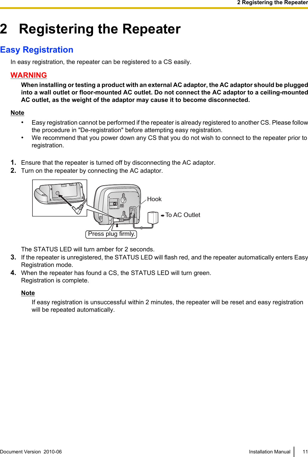
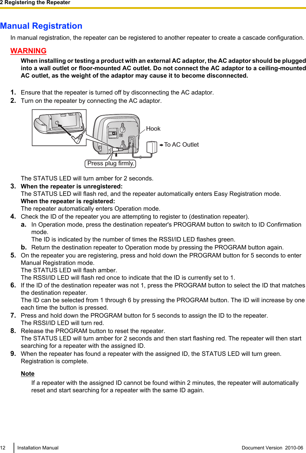
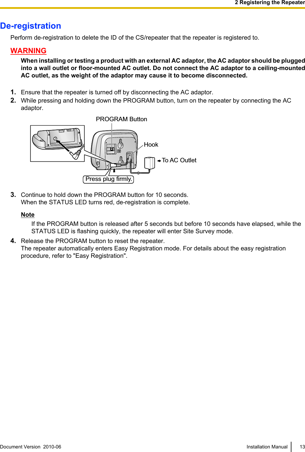
Panasonic Corporation of North America DECT 6.0 Repeater for PBX Installation Manual English
UserManual.wiki
>
Panasonic of North America
>
96NKX A405 User Manual
User Manual
Navigation menu
Upload a User Manual
Namespaces
Wiki Guide
HTML
PDF
Info
Views
User Manual
Discussion / Help
Navigation
![Important InformationSAVE THESE INSTRUCTIONSSafety NoticesPlease observe the safety notices in this manual in order to avoid danger to users or other people, and preventdamage to property.The notices are classified as follows, according to the severity of injury or damage:WARNING This notice means that misuse could result in death or serious injury.CAUTION This notice means that misuse could result in injury or damage toproperty.WARNINGSAFETY REQUIREMENTS•The product must only be installed and serviced by qualified service personnel. The product should beused as-is from the time of purchase; it should not be disassembled or modified. Disassembly ormodification can cause a fire, electric shock, or damage to the product.•Make sure that the wall that the unit will be attached to is strong enough to support the unit (approx.80 g [2.8 oz]). If not, it is necessary for the wall to be reinforced.•Only use the wall-mounting equipment (screws, washers) included with the unit.•When this unit is no longer in use, make sure to detach it from the wall.•Do not connect or disconnect the AC plug with wet hands.•Disconnect the unit from the AC outlet and contact the dealer if:–The AC adaptor cord or AC plug becomes damaged or frayed.–The unit is exposed to rain, water, or any other liquid.–The unit is dropped or damaged.–Internal components are exposed due to damage.–The unit does not operate properly.–Performance deteriorates.•Disconnect the unit from the AC outlet if the unit emits smoke, an abnormal smell, or makes unusualnoise. These conditions can cause fire or electric shock. Confirm that smoke has stopped and contactan authorized service center.•Clean the AC plug periodically with a soft, dry cloth to remove dust and other debris.•Do not touch the unit or AC adaptor during a lightning storm.•Use only the included AC adaptor (PQLV219).•Do not allow anything to rest on the AC adaptor cord. Do not locate this unit where the AC adaptorcord may be stepped on or tripped on.CAUTIONSAFETY REQUIREMENTS•The unit should be kept free of dust, moisture, high temperature (more than 40 °C [104 °F]), lowtemperature (less than 0 °C [32 °F]), and vibration, and should not be exposed to direct sunlight.•The unit should not be placed outdoors (use indoors).•The unit should not be placed near high-voltage equipment.•The unit should not be placed on a metal object.2 Installation Manual Document Version 2010-06 Important Information](https://usermanual.wiki/Panasonic-of-North-America/96NKX-A405/User-Guide-1306711-Page-2.png)
![ID ModificationIn ID Modification mode, the ID of the repeater (RPN [Radio Part Number]) can be selected. Registeredrepeaters are automatically assigned an ID during the registration process. This ID can be changed by followingthe procedure below.1. In Operation mode, or Easy Registration mode if the repeater is unregistered, press and hold down thePROGRAM button for 8 seconds to enter ID Modification mode.The STATUS LED will turn amber.The RSSI/ID LED will flash red once to indicate that the ID is currently set to 1.2. Press the PROGRAM button to select the desired ID.The ID can be selected from 1 through 6 by pressing the PROGRAM button. The ID will increase by oneeach time the button is pressed.3. Press and hold down the PROGRAM button for 5 seconds to assign the ID to the repeater.The RSSI/ID LED will turn red.4. Release the PROGRAM button to reset the repeater.The STATUS LED will turn amber for 2 seconds and then the repeater will return to Operation mode, orEasy Registration mode if the repeater is unregistered.14 Installation Manual Document Version 2010-06 2 Registering the Repeater](https://usermanual.wiki/Panasonic-of-North-America/96NKX-A405/User-Guide-1306711-Page-14.png)
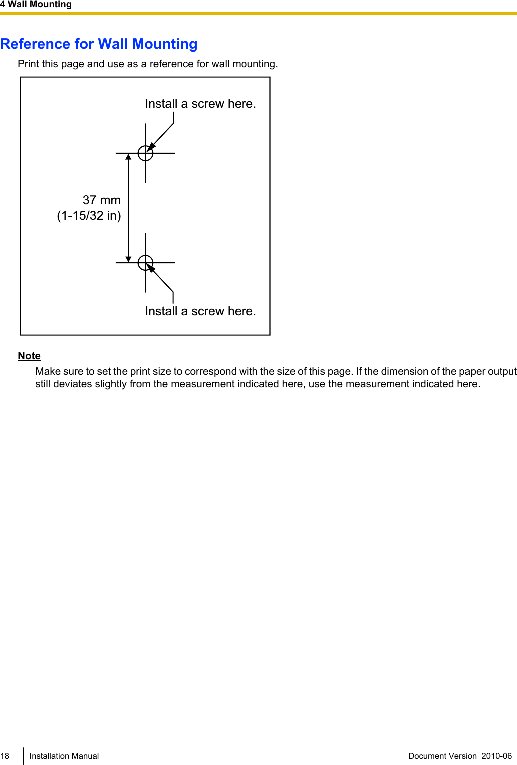
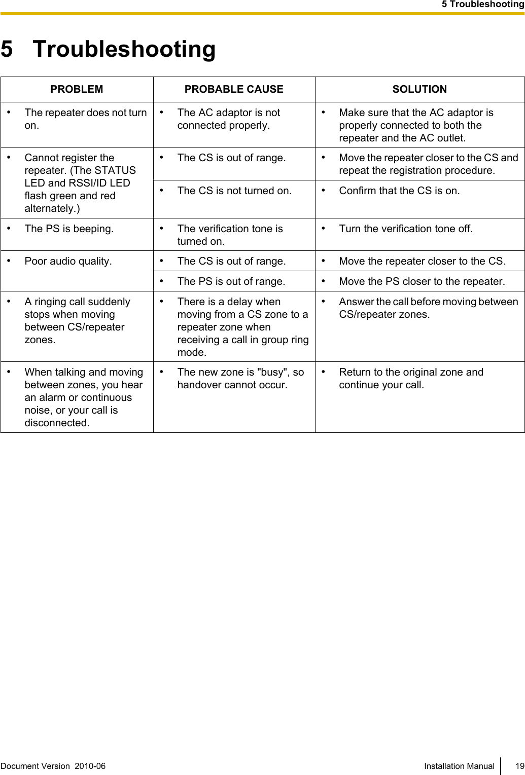
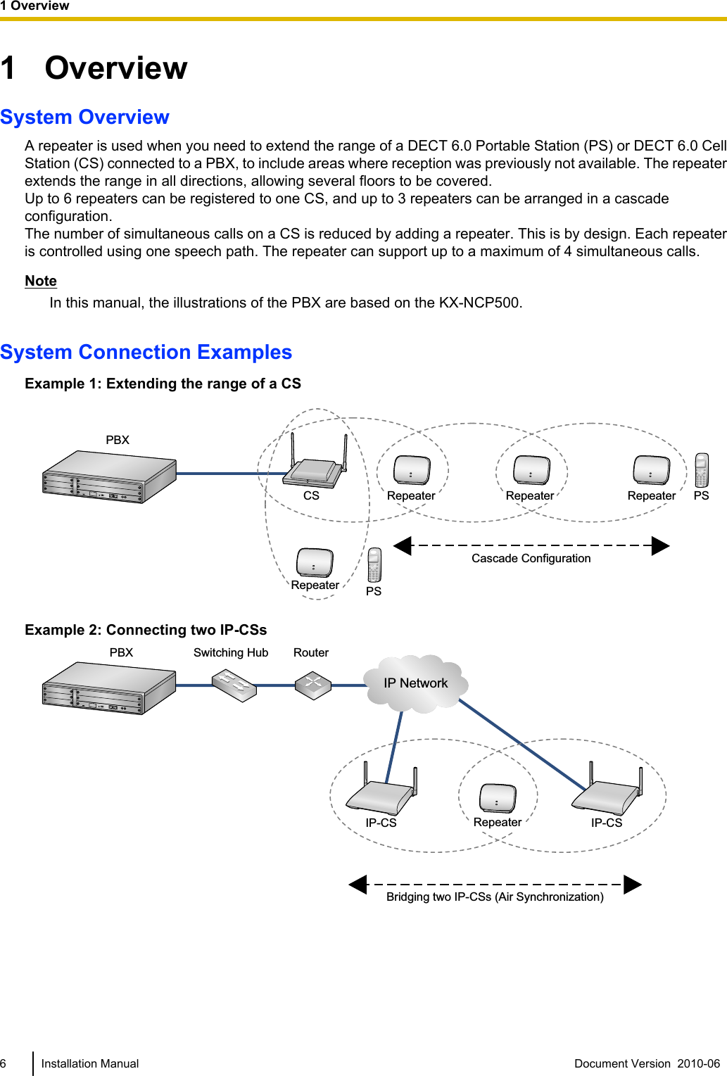
![4 Wall MountingMountingWARNING•Make sure that the wall that the unit will be attached to is strong enough to support the unit(approx. 80 g [2.8 oz]). If not, it is necessary for the wall to be reinforced.•Only use the wall-mounting equipment (screws, washers) included with the unit.•When this unit is no longer in use, make sure to detach it from the wall.CAUTION•When driving the screws into the wall, be careful to avoid touching any metal laths, wire laths or metalplates in the wall.•Do not stretch or bend the cable. Also, do not allow anything to rest on the cable.•The unit and the cable should never be placed near or over a radiator or other heat source.•Do not bundle the cable that is connected to the unit with the AC power cords of machines locatednearby.•Make sure the cable is securely fastened to the wall.1. Place the reference for wall mounting on the wall to mark the 2 screw positions.2. Install the 2 screws and washers (included) into the wall.Note•Make sure that the screw heads are at the same distance from the wall.•Install the screws perpendicular to the wall.3. Hook the repeater on the screw heads.WasherDrive the screw to this point.Document Version 2010-06 Installation Manual 174 Wall Mounting](https://usermanual.wiki/Panasonic-of-North-America/96NKX-A405/User-Guide-1306711-Page-17.png)